

Page 1

Chapter 1
Manual Front Cover
PACEMARK 3410 Printer Handbook
for Epson/IBM & Microline/Pacemark Models
PN 59249101, PM3410, PACE, PM3FM, 12/91, Final
ML3410 ( 96-02-07 )
Page 2
Chapter 1
Setup
Setup
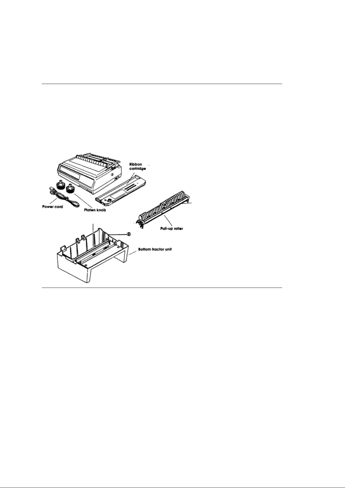
Unpack your printer and make sure you have the following items:
Pacemark 3410 Printer Platen knob
Power cord Ribbon cartridge
Sheet separator (w/rollers)Bottom tractor unit
Printer Handbook
If you are missing any of these items, contact your dealer.
ML3410 ( 96-02-07 )
Page 3

Preliminaries
Preliminaries
After unpacking the printer, there are a few minor tasks that must be performed
ML3410 ( 96-02-07 )
Page 4
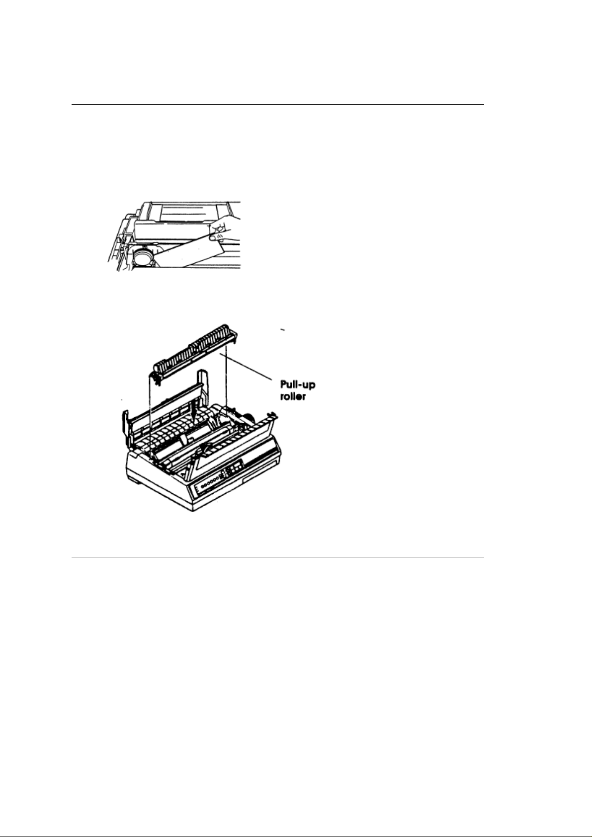
Remove shipping restraint
Remove shipping restraint
After unpacking the printer, there are a few minor tasks that must be performed before you can
begin.
1. Open the front cover of the printer.
2. Remove the shipping restraint located under the printhead.
3. Open the rear cover. Set the pull-up roller on the printer so that the tabs on the roller are in the
grooves in the printer.
Save the shipping restraint and the packing material for reshipping.
ML3410 ( 96-02-07 )
Page 5
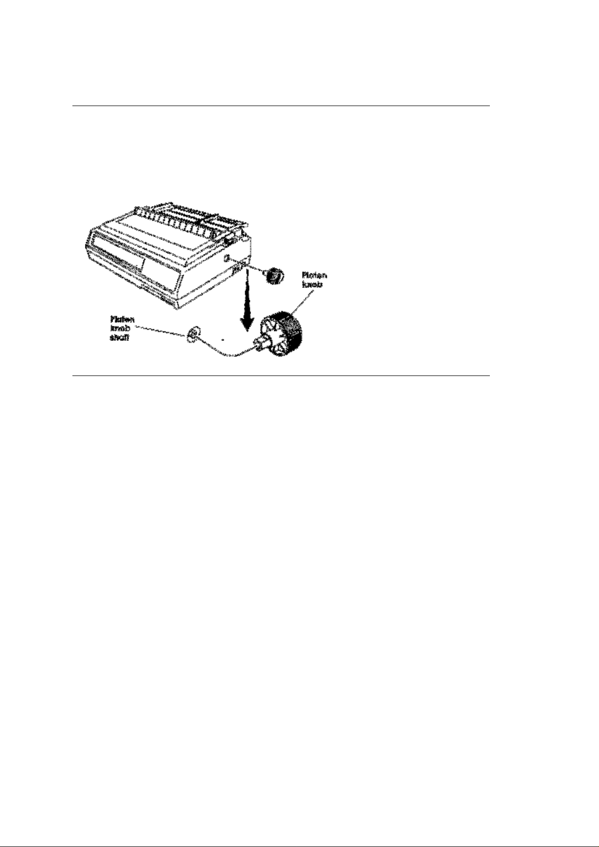
Installing the Platen Knob
Installing the Platen Knob
You will notice that the shaft on the platen knob has a flat side that matches the flat side of the shaft
in the printer.
1. Line up the flat side of the platen knob shaft with the flat side of the printer shaft.
2. Push the knob into place.
ML3410 ( 96-02-07 )
Page 6
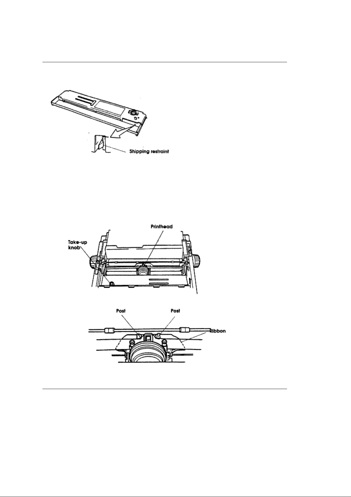
Inserting the Ribbon
Inserting the Ribbon
1. Unpack the ribbon and remove the shipping restraint.
2. Push the idler roller latch in.
3. Lay the ribbon in the printer so that the pins on the cartridge fit into the notches in the side plates
of the printer. Push down on the cartridge until it clicks into place (See the diagram on the
cartridge).
Note
Turn the knob in the direction of the arrow if the cartridge doesn't fit into place easily.
4. Center the printhead.
5. Thread the ribbon around the posts as shown.
6. Turn the take-up knob clockwise to take up the slack in the ribbon.
ML3410 ( 96-02-07 )
Page 7
The Bottom Feed Tractor Unit
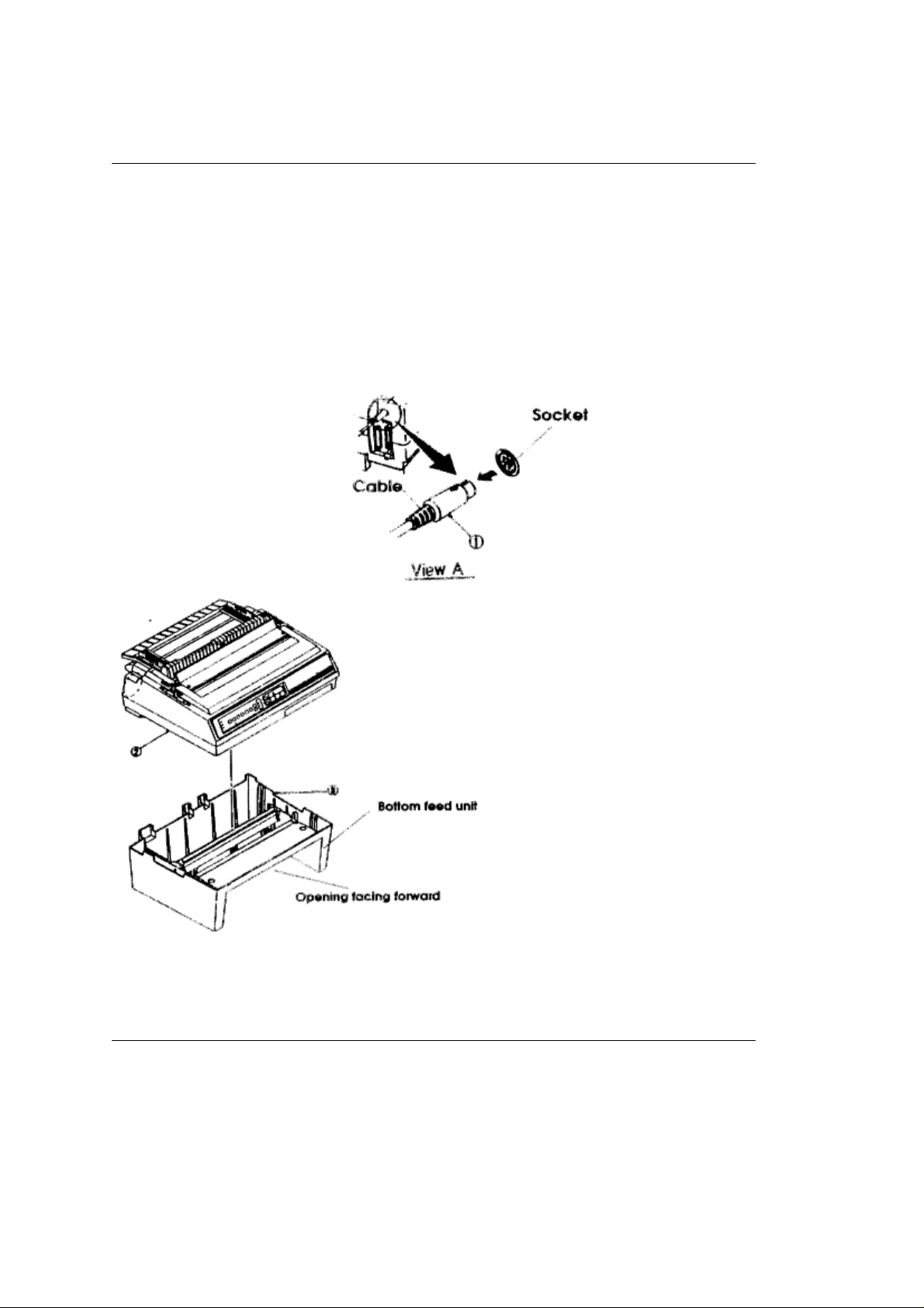
The Bottom Feed Tractor Unit
This separate unit makes it easy and convenient for you to use continuous forms paper fed from the
bottom of the printer.
To install the bottom feed unit:
1. Place the unit where you plan to put the printer. The opening in the unit should face the same
direction as the front of the printer.
2. Pick up the printer and put it on top of the bottom feed unit as shown. Be sure the printer is firmly
seated on the unit.
3. Plug the cable on the unit into the round socket above the parallel interface connector on the
back of the printer. The arrow on the plug faces up.
Caution
Do not attempt to pick up the printer and bottom feed unit together. Disconnect the printer from
the bottom feed unit
and move them separately.
ML3410 ( 96-02-07 )
Page 8
Making Connections
Making Connections
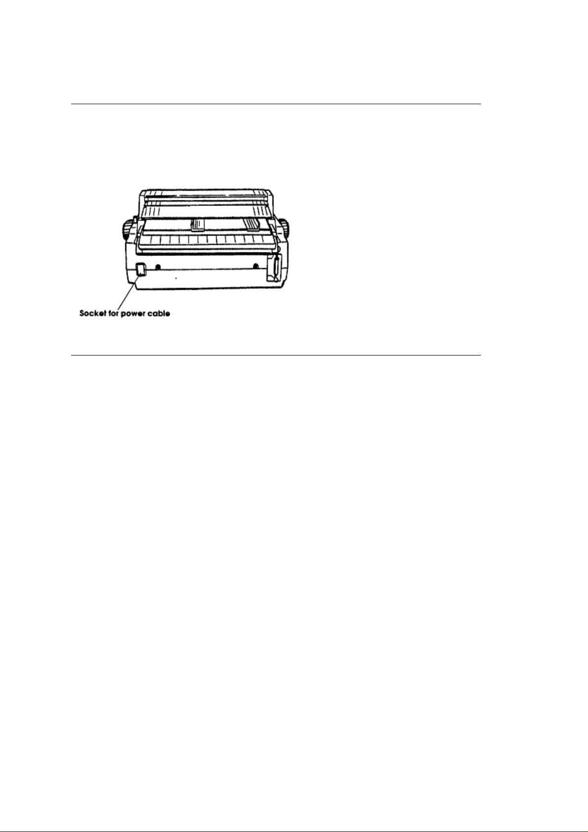
The power cable and the interface cable have to be connected before you can use your printer. Before
you begin, make sure that the power switch is off.
Plug the power cord into the printer, but do not plug it into an electrical outlet until setup is complete.
ML3410 ( 96-02-07 )
Page 9
Choosing Parallel or Serial
Choosing Parallel or Serial
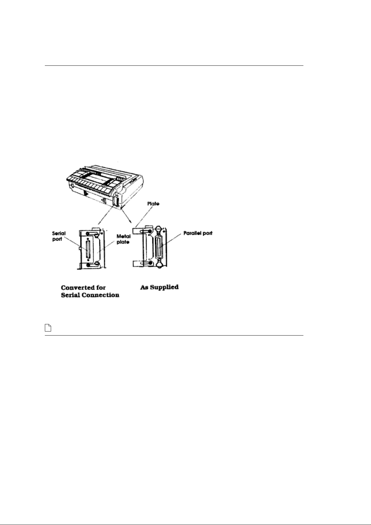
Your Pacemark 3410 has both a parallel and a serial port. All you have to do is decide which one
you want to use. You can only use one of them at a time.
When you take the printer out of the box, there will be a metal plate over the serial port. If you want
to use the parallel port, just plug in your cable and fasten the clips to it.
If you want to use the serial interface, loosen the metal plate with a Phillips screwdriver and slide it
to the right to uncover the serial port. Plug your cable into the serial port and tighten the screws.
You can fasten the metal plate over the parallel port to eliminate confusion in the future.
You can fasten the metal plate over the parallel port to eliminate confusion in the future. If you use the
serial port, you may have to enter the Menu Select mode and adjust the menu settings. See Chapter 3 (
) for an explanation of the Menu Select mode.
ML3410 ( 96-02-07 )
Page 10
Adjusting the HeadGap
Adjusting the HeadGap
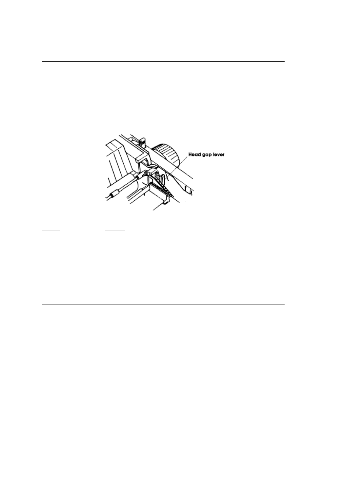
The headgapis the distance between the printhead andthe roller. When you use envelopes or multi-part
forms, you want to have a larger head gap than when you use plain paper. Use the recommended head
gap to ensure the best print quality and easy paper feeding.
To adjust the head gap, open the front cover. The blue head gap lever is located on the right side of the
printer. Use the following chart to determine the proper head gap for your needs.
Paper Setting
12-24 lb. paper 1
Labels 3-4
Envelopes 5-9
Forms (w/carbon)
Two-part 2-3
Three-part 3-4
Four-part 5
Five-part 6
Six-part 7
ML3410 ( 96-02-07 )
Page 11

Testing Your Printer
Testing Your Printer
Your Pacemark printer has two built-in tests to make sure your printer is working properly. Run these
after you've set up your printer and any time you want to verify that it•s running. The top of each print test
contains information on your printer model. Be sure to have a copy of the printout handy if you call for
service.
Important
Use only continuous forms paper to run these tests.
Print Sample Test
Turn the printer on while holding down the LINE FEED button. The test prints a two-page sample of your
Pacemark•s printing styles. Press the SELECT button or turn off the printer to stop the test.
Rolling ASCII Test
Turn the printer on while holding down the FORM FEED button. This test prints the character set in a
rolling pattern using the default type style. Press the SELECT button or turn off the printer to stop the
test.
ML3410 ( 96-02-07 )
Page 12

Chapter 2
Loading Paper
Loading Paper
The Pacemark 3410 has three standard paper handling configurations: rear-fed continuous forms,
bottom-fed continuous forms and top-fed single sheets. All three are flexible and trouble-free.
ML3410 ( 96-02-07 )
Page 13
Rear Feed Continuous Forms
Rear Feed Continuous Forms
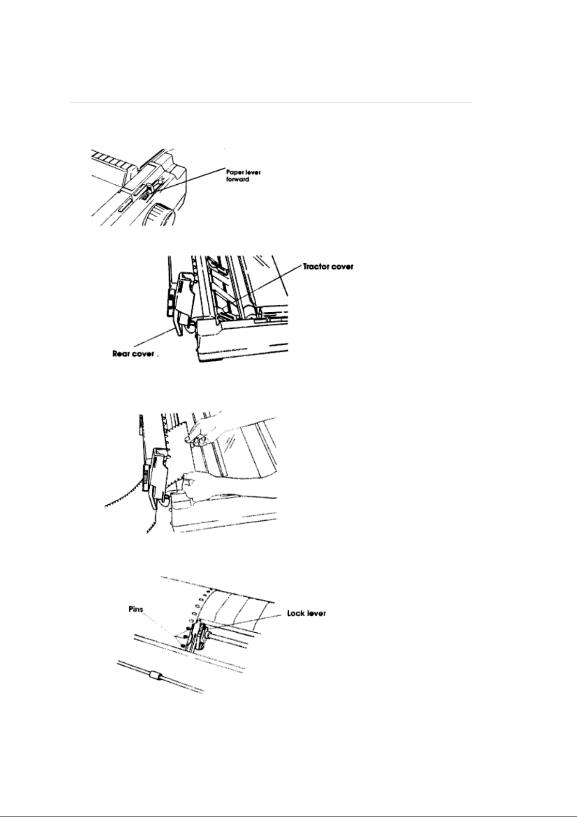
1. Pull the paperlever forward to the continuous forms position.
2. Open the rear cover.
3. Insert the paper under the rear cover and pull it through.
4. Open the tractor covers and set the paper on the pins.
5. Pull the lock lever forward to unlock the tractor.
6. Slide the tractor to adjust to the width of the paper then push the lock lever back to lock the
tractor in position. Don't stretch the paper tightlyit can cause the paper to tear.
7. Close the tractor covers.
ML3410 ( 96-02-07 )
Page 14
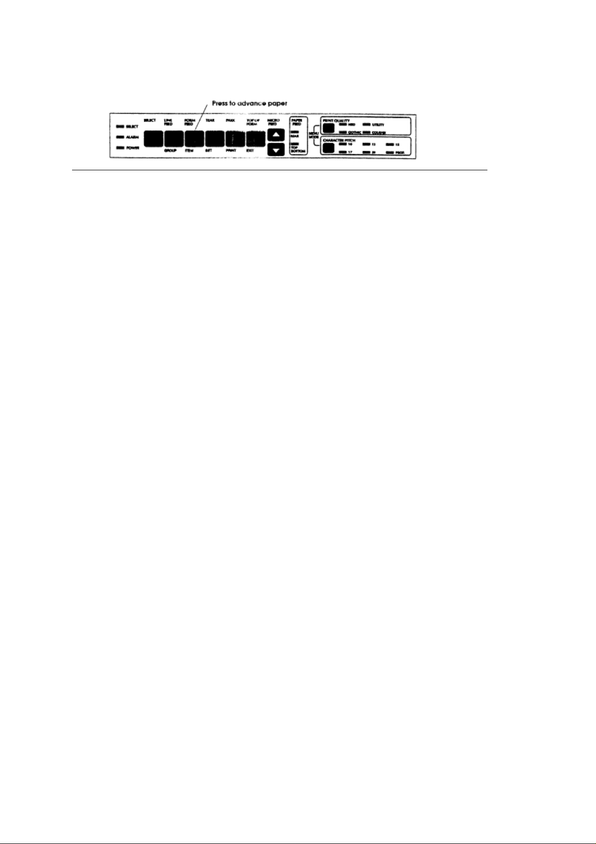
8. Close the rear cover.
9. Press the FORM FEED button to advance the paper.
ML3410 ( 96-02-07 )
Page 15
Bottom Feed Continuous Forms
Bottom Feed Continuous Forms
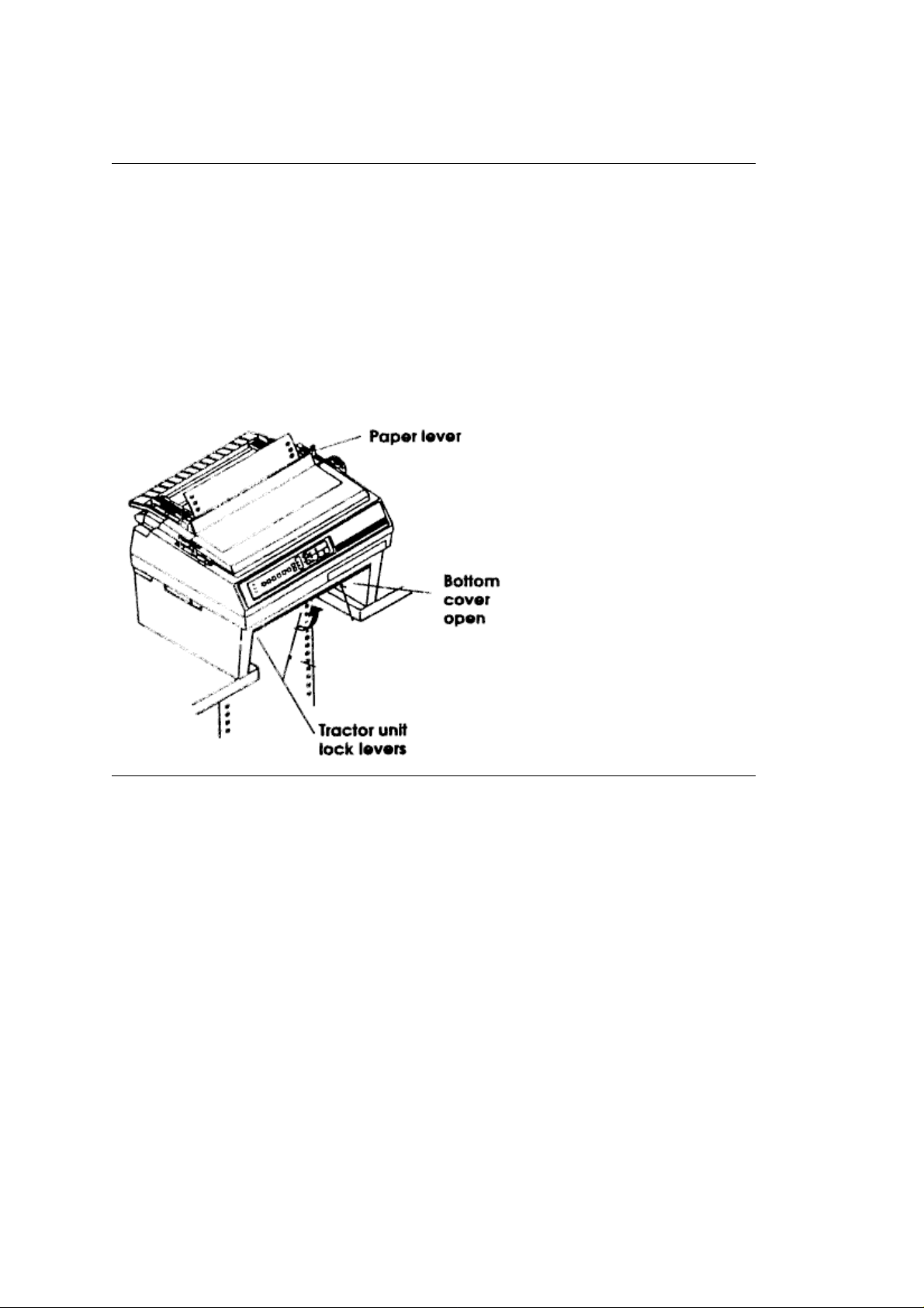
1. Make sure the paper lever is set for single-sheet paper
2. Put a stack of continuous forms paper below the printer.
3. Open the door on the front of the tractor unit.
4. Open the tractor covers and set the paper on the pins.
5. Pull the lock lever forward to unlock the tractor.
6. Slide the tractor to adjust to the width of the paper, then push the lock lever back to lock the
tractor in position.
7. Close the tractor covers and the unit door.
8. Make sure the printer is on and selected. Press the FORM FEED button to advance the paper
into the printer.
(back).
ML3410 ( 96-02-07 )
Page 16

Form Tear Off (continuous form paper only)
Form Tear Off (continuous form paper only)
This feature lets you remove a printed page from the printer without wasting paper. Activate it by
changing the setting for the Form Tear Off menu selection to 500ms, 1 sec, or 2 sec. (See Chapter 3 (
for details on the printer menu.)
Note
Keep in mind that there are separate menu groups for each of the three possible paper paths. Be sure to
activate the Form Tear Off selection for the one you are using, rear feed or bottom feed.
After you load paper and press the FORM FEED button, the paper will advance past the printing (top of
form) position to the tear bar position. It stays in this position until the printer receives data; the paper
then moves back down for printing. A few seconds after printing stops, the paper moves back to the tear
bar
so you can tear it off without feeding an extra sheet of paper.
You can check the top of form position by pressing the TEAR button. Release the button to return to the
tear off position.
)
ML3410 ( 96-02-07 )
Page 17
Single-Sheet Paper
Single-Sheet Paper
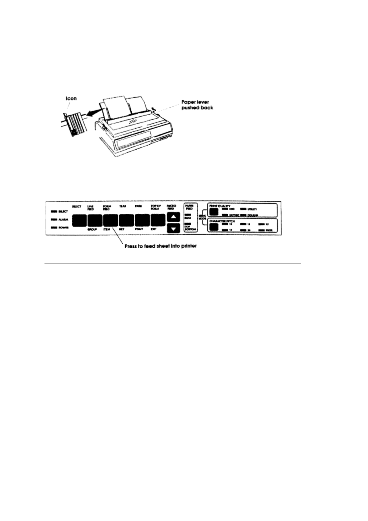
1. Push the paper lever back to the single sheet position.
2. Lift the paper support to the upright position.
3. Align the left paper guide with the paper icon on the support.
4. Insert a piece of single-sheet paper and adjust the right paper guide to the width of the paper.
5. Press the FORM FEED button to feed the sheet into the printer.
ML3410 ( 96-02-07 )
Page 18
Setting Top of Form
Setting Top of Form
The top of form is the place on the page where printing starts. When the printer advances to the
next page, it stops at the top of form.
Your Pacemark printer stores the top of form position independently for the three standard types of
paper feeding top, rear, and bottom.
The method of setting top of form is the same for all types of paper:
1. Feed a page into the printer by pressing the FORM FEED button.
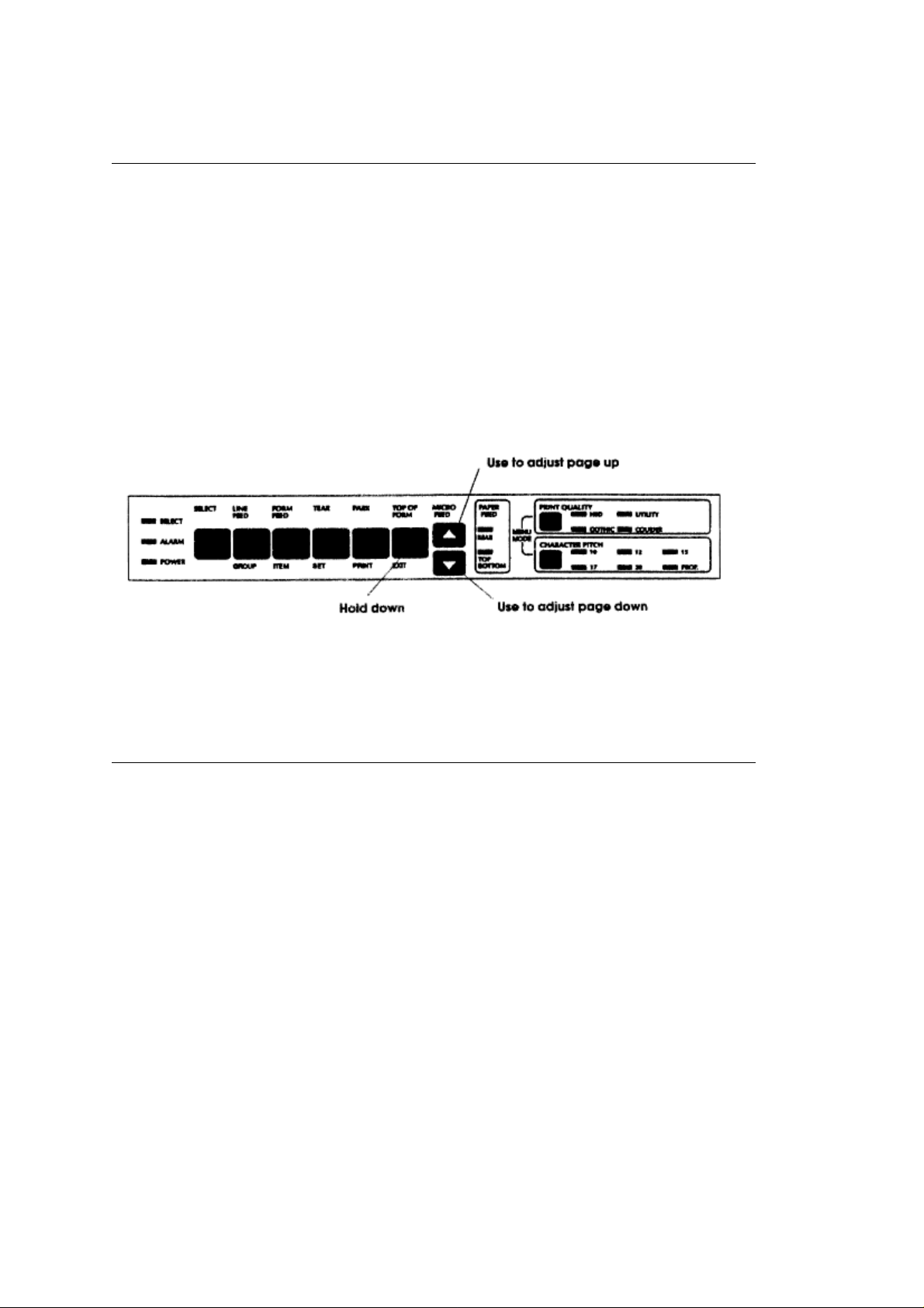
2. Hold down the TOP OF FORM button while you adjust the page up or down using the MICRO
FEED buttons. The red line on the plastic ribbon shield marks the base of the printing line•use
this as a guide.
3. When you release the TOP OF FORM button, the position will be registered in the printers
memory until you change it.
Note
If you want to reset the top of form to its original settings, turn off the printer, then hold down the
SELECT and TOP OF FORM buttons while turning it on again. Keep in mind, however, that this
will also cancel any changes you've made to the menu.
ML3410 ( 96-02-07 )
Page 19

Changing Paper Types
Changing Paper Types
You don't have to remove continuous forms paper in order to print a single sheet. With the touch of
a button you can switch from one type of paper to another.
To change from continuous forms to single sheets:
1. Remove any printed pages from the printer.
2. Press the PARK button to retract the continuous forms paper from the paper path.
3. Move the paper lever to the single sheet position if you're switching from rear feed.
4. Follow the instructions under Single-Sheet Paper for loading single sheets.
To change back to continuous forms:
1. Remove any single-sheet paper in the printer.
2. Move the paper lever to the continuous forms position if youre switching to rear feed, leave it set
for single sheets if you're switching to bottom feed.
3. Lower the paper support.
4. Press the FORM FEED button to feed continuous forms paper into the printer.
ML3410 ( 96-02-07 )
Page 20

The Optional Pull Tractor
The Optional Pull Tractor
This option is available for specialized bottom feed applications where a pull tractor is required, either
alone or in combination with the bottom feed unit.
ML3410 ( 96-02-07 )
Page 21
Installing the Optional Cut Sheet Feeder
Installing the Optional Cut Sheet Feeder
A Cut Sheet Feeder (CSF) is ideal for high-volume printing using single-sheet paper. The CSF
feeds paper automatically, controlled from the printer•s front panel or from the computer.
There are two cut sheet feeders available for the Pacemark 3410: the single-bin CSF 3001 and the
dual-bin CSF 3002. Since both feeders are installed in the same way, we•ll illustrate the
procedure with the CSF 3001, noting any differences as they arise.
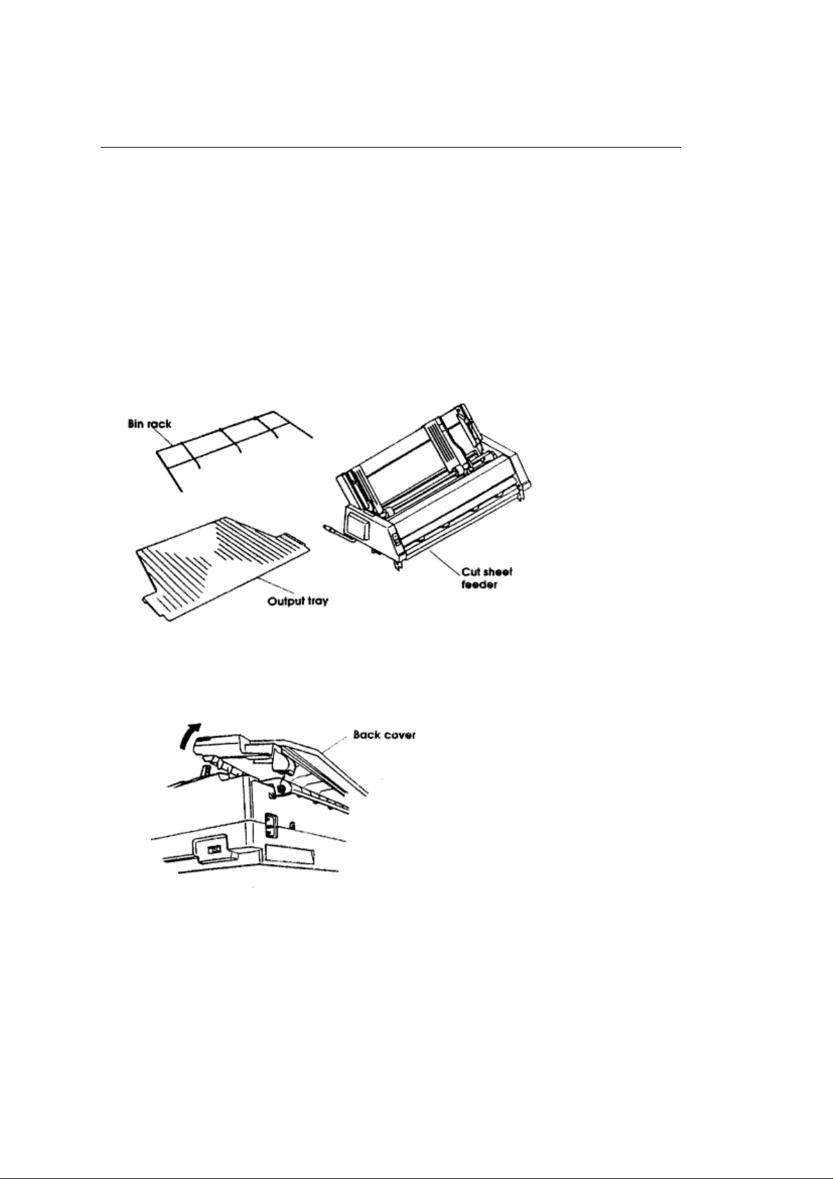
Unpack your cut sheet feeder and make sure you have all the parts.
- Cut Sheet Feeder
- Bin rack (1 for the CSF 3001 and 2 for the CSF 3002)
- Output tray
1. Make sure the printer is off.
2. Open the front cover.
3. Remove the back cover: tilt it back slightly and lift it off.
4. Push the bail lever forward to the open position and the paper lever back to the single sheet
position.
5. Hold the cut sheet feeder over the printer.
6. While fitting the CSF hooks over the platen shaft, gently lower it onto the printer.
ML3410 ( 96-02-07 )
Page 22
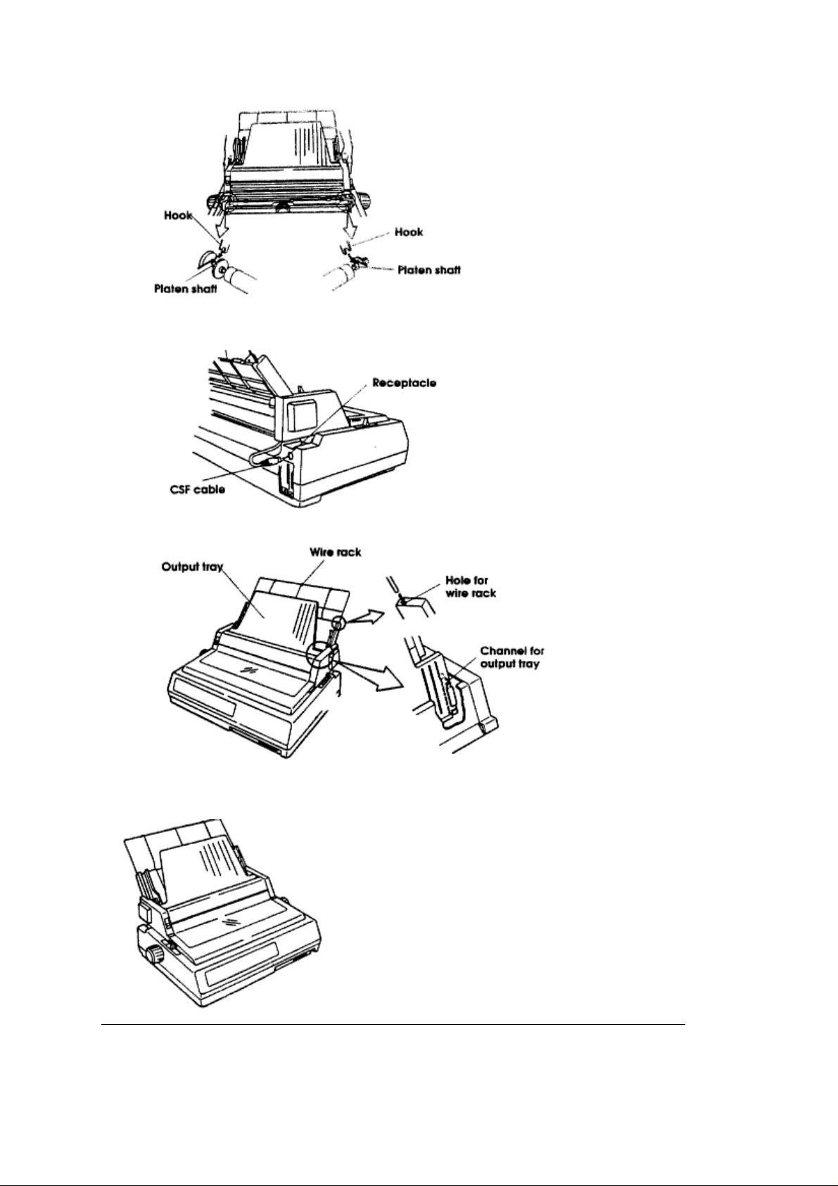
7. Unplug the bottom feed tractor cable and plug the CSF cable into the receptacle on the printer.
The arrow on the plug faces up.
8. Fit the wire rack(s) into the hole(s) on the back of the bins.
9. Slide the output tray into the channels on the sides of the CSF.
This is what the finished product should look like:
ML3410 ( 96-02-07 )
Page 23
Loading the CSF
Loading the CSF
Each bin of the optional CSF3001 and CSF3002 holds up to 130 sheets of 20lb. paper or between
100 and 120 sheets of 24 lb. paper, depending on thickness and texture.
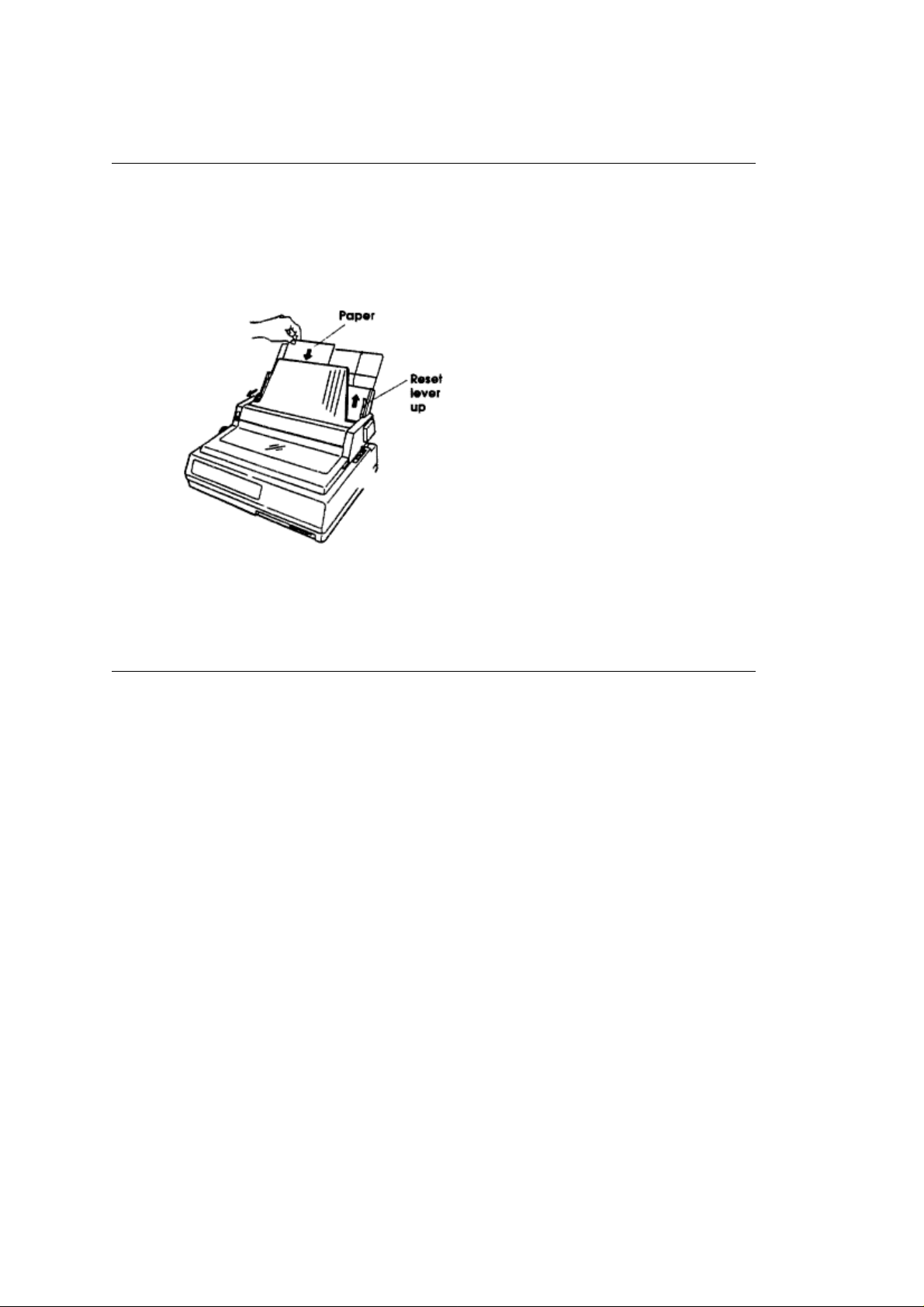
1. Push the reset lever up to load paper and the envelope lever forward for paper.
2. Make sure the paper lever is in the single sheet position.
3. Fan a stack of paper and square it. Put the paper in the paper bin.
4. Adjust the paper guides to the width of the paper.
5. Once the paper is in the proper position, push the reset lever down.
4. Adjust the paper guides to the width of the paper.
5. Once the paper is in the proper position, push the reset lever down.
6. Push the FORM FEED button to insert a sheet of paper.
7. To eject a page, press the FORM FEED button again.
ML3410 ( 96-02-07 )
Page 24
Switching Bins
Switching Bins
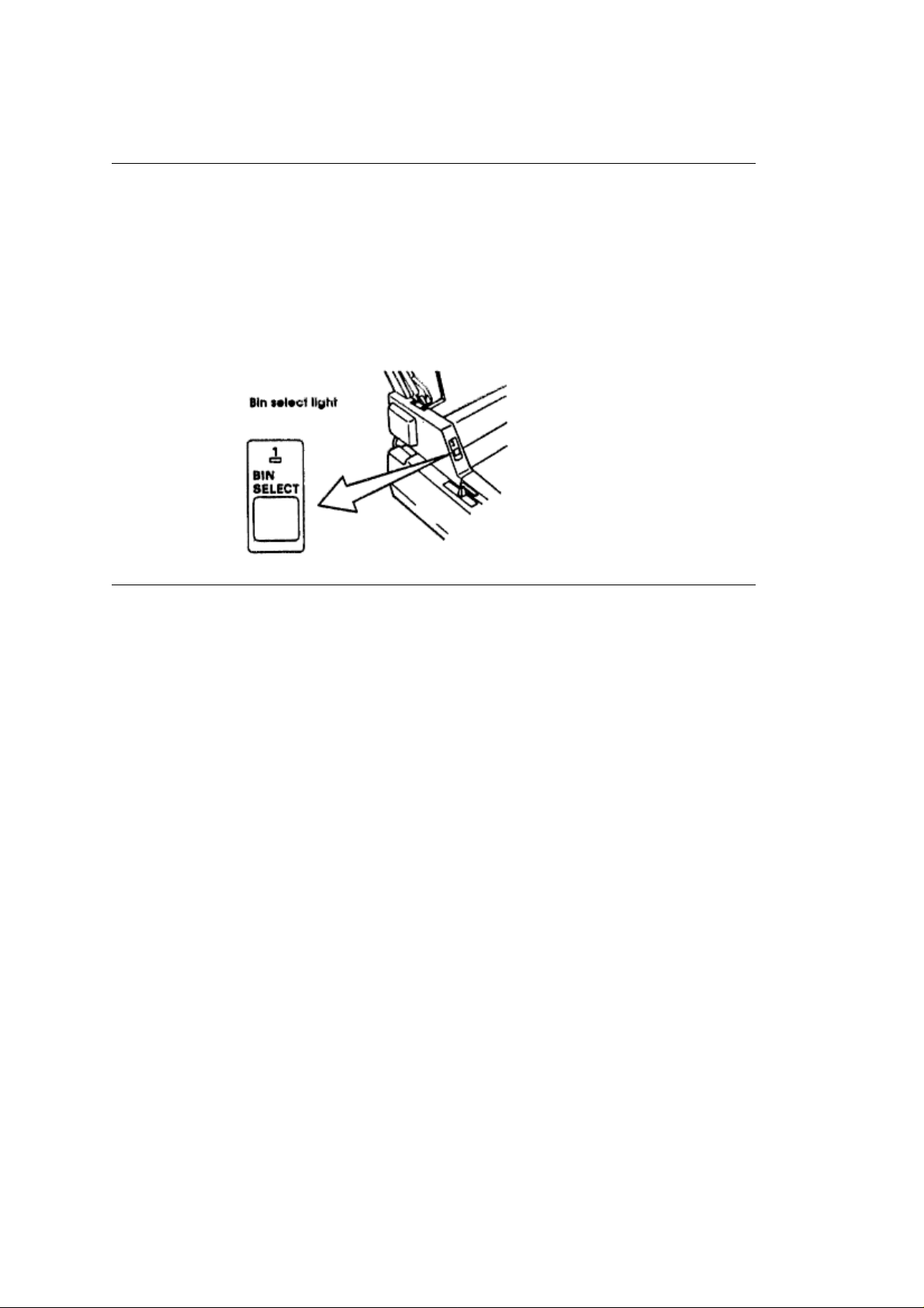
If you have the CSF3002, you can move from one bin to another. When the BIN SELECT light is
on, you are using bin number 1
To move to bin two:
1. Make sure that the printer is deselected. Press the SELECT button if the SELECT light is on.
2. Press the BIN SELECT button. The BIN SELECT light should go out. When the BIN SELECT
light is out, you are using bin number 2.
ML3410 ( 96-02-07 )
Page 25

Printing Envelopes with the CSF
Printing Envelopes with the CSF
You can use #10 envelopes (standard business size) in your CSF3001 and in the front bin only of
the CSF 3002.
Be sure to adjust the head gap lever (5-9) and push the envelope lever back.
Load envelopes with the flaps facing down and toward the front of the printer. Set the envelope
lever to the rear.
For best results, avoid printing on areas where the flap overlaps the envelope. Printing may be
uneven in places where the envelope varies in thickness.
ML3410 ( 96-02-07 )
Page 26

Chapter 3
Operation
Operation
The Pacemark 3410 has a control panel that lets you select the character pitch
and print quality, control paper feeding, and customize your printer settings with the touch of a button.
You don't have to be a programmer or a computer expert to learn how to use it.
The control panel always shows the actual settings of the printer. If you change any of these features
through your computer, the panel lights will also change.
Some features will only function if you have the correct settings on your control panel. The panel will only
let you select valid combinations of features.
There are three sections to the control panel:
¨ Basic Control
¨ Print Quality
¨ Character Pitch
ML3410 ( 96-02-07 )
Page 27

Basic Control
Basic Control
The basic control portion of the panel displays the status and controls the basic functions of the
printer.
There are five lights in this part of the panel. They reflect the printer status at any given time.
1.
POWER light:
2.
ALARM light:
printer is out of paper, and so on.
3.
SELECT light:
lit, the printer is deselected and can•t receive data. If the light flashes, there•s a problem with the
printer that requires service.
4.
PAPER FEED lights:
Your printer has two modes of operation: Print mode and Menu Select mode. You will notice that
there are functions printed above and below the basic control buttons.
The functions above the buttons are active during Print mode; those below the buttons are active during
Menu Select mode.
The POWER light is lit whenever the printer is on.
This light is lit when an error condition exists such as a paper jam, cover open, the
This light is lit when the printer is ready to receive data. If the SELECT light is not
these lights indicate which paper path is active.
ML3410 ( 96-02-07 )
Page 28

Print Mode
Print Mode
When you turn your printer on, it is in Print mode. Print mode is the state of
normal operation.
In Print mode, the functions above the basic control buttons are active.
1.
SELECT button:
second time to enable the printer to receive data again (SELECT light goes on).
2.
LINE FEED button:
3.
FORM FEED button:
4.
TEAR button:
position. This allows you to tear off a printed page without wasting an extra sheet of paper. See
page 16 for details (
5.
PARK button:
lets you use single sheet paper without removing the continuous forms. See 18 for details (
6.
TOP OF FORM button:
the point on the page at which printing starts. When you press the FORM FEED button, the new
page advances to this line.
7.
MICRO FEED buttons:
hold down the TOP OF FORM button while using the MICRO FEED buttons, the top of form will
automatically be set when you release the buttons.
Press this button to deselect the printer (SELECT light goes out). Press it a
Press this button to advance the paper one line at a time.
Press this button to advance the paper one page at a time.
Press this button to advance the paper from the printing position to the tearoff
).
Press this button to retract continuous forms paper out of the paper path. This
When the printer is deselected, pressing this button sets the top of form
Pressing these buttons feeds paper up or down in fine increments. If you
).
ML3410 ( 96-02-07 )
Page 29

Print Quality
Print Quality
This allows you to select the level of printing quality suitable to your needs.
High Speed Draft (HSD) is the fastest printing mode (550 characters per second). It's suited for situations
where speed is more important than appearance, such as editing or proofing a document before final
printing.
Utility printing is for everyday use, such as memos and internal documents.
When you want correspondence and documents to look their best, use one of the two Near Letter Quality
typefaces: Courier and Gothic.
Press the PRINT QUALITY button until the light next to your choice is lit.
ML3410 ( 96-02-07 )
Page 30

Character Pitch
Character Pitch
With the Character Pitch feature, you can choose between 10, 12, 15, 17.1, and 20
characters per inch and PROPortional spacing at the touch of a button.
Press the CHARACTER PITCH button to cycle through the choices.
Note
Proportional spacing is not available with HSD.
ML3410 ( 96-02-07 )
Page 31

Menu Select Mode
Menu Select Mode
You can customize your printer directly fromthe front panel by using the Menu Select mode.It lets you
choose your own printer defaults settings and features automatically active when you turn it on.
ML3410 ( 96-02-07 )
Page 32

Entering Menu Select Mode
Entering Menu Select Mode
Be sure that your printer has ribbon and paper. Press both the PRINT QUALITY button and the
CHARACTER PITCH button to enter the Menu Select mode.
When you're in Menu Select mode, the functions written below the buttons are active. For example, the
TOP OF FORM button is now the EXIT button.
ML3410 ( 96-02-07 )
Page 33

Exiting Menu Select Mode
Exiting Menu Select Mode
If you want to leave Menu Select mode at any time just press the EXIT button.
ML3410 ( 96-02-07 )
Page 34

Understanding the Menu Select Mode
Understanding the Menu Select Mode
The Menu Select mode is just a menu of the Pacemark features. You may want to
change the default settings of some of those features to fit your needs. For
example, you may want to change the page length to 14 inches if you print alot of
legal size documents or 3 inches if you(re working on labels or small cards.
The menu is made up of a number of groups.Within each of thesegroups is a list
of items,and each of those items has several settings.
ML3410 ( 96-02-07 )
Page 35

Making Selections
Making Selections
Before you begin, press the PRINT button to get a list of groups, items, and settings. This list will
tell you what the current settings are for your printer. Use this list to find your way around in the
menu.
Each time you press the GROUP, ITEM, or SET button, the appropriate menu line will print on the
paper.
Press the GROUP button to move from group to group. If you pass the group that you want, just
keep cycling through. It will come up again. Press the ITEM button to move between the items in
a group.
Press the SET button to cycle through the settings for an item. To choose a setting, press the SET
button until you come to the setting you want then press the ITEM button to move on to the next
item.
Press the EXIT button to save your changes and leave the menu.
See Appendix A for a list of the menu items and factory settings (
Note
To reset the printer to the factory menu settings, turn the printer off, then hold down the SELECT
and LINE FEED buttons while you turn it back on.
To reset both the menu and the paper loading position, turn the printer off, then hold down the
SELECT and TOP OF FORM buttons while you turn it back on.
).
ML3410 ( 96-02-07 )
Page 36

Chapter 4
Computer Control
Computer Control
This chapter explains the basics of controlling the printer through your computer. It covers the
fundamentals of setting up a software package for use with your printer, MS-DOS printing commands,
and provides some tips on writing BASIC programs to control your printer. This information should help
you get started; be sure to read your software documentation carefully for more details.
ML3410 ( 96-02-07 )
Page 37

DOS 2.0 and Higher
DOS 2.0 and Higher
Most IBM PC and compatible personal computers use PC-DOS or MS-DOS as their operating system.
Although DOS is much more limited in printing capabilities than word processing or graphics software,
there are some commands in DOS 2.0 and higher that you can use to control your printer.
ML3410 ( 96-02-07 )
Page 38

DOS Commands for Printing Text Files
DOS Commands for Printing Text Files
¨ PRINT filename
¨ TYPE filename > devicename
¨ COPY filename devicename
If you've used a word processor or other software package to prepare your document, it's usually easiest
to use that packages print commands to print it. This is particularly true if the software lets you control a
documents appearance, page length, margins, printing features, and so on.
However, if your software doesnt control these kinds of features, it's just as easy to print using DOS
commands. Some packages even have a print to disk feature, so you can save the file on a disk in a
format that DOS can later read and send to the printer.
ML3410 ( 96-02-07 )
Page 39

DOS PRINT
PRINT
PRINT is a background utility that lets you print a file while you•re running another program. Once you•ve
given the command to print your file, you can go on to another task on your computer without waiting until
printing is finished.
PRINT is not a DOS command but a separate program, so if you want to use it, the file
Note
PRINT.COM must be on one of your disks.
Example
In this example, we•re going to print a file called NOTES.TXT, which is on the WORK subdirectory of the
computer•s hard disk drive (drive C:). The PRINT.COM program file is in the main (root) directory of the
C: drive.Begin by typing the following at the C> prompt:
PRINT C: \WORK\NOTES.TXT [RETURN]
Youll see this display on your screen:
Name of list device [PRN]:
If your printer is connected to the LPT1: parallel printer port, just press [RETURN]; if its connected to
another port (LPT2:, COM1:, or COM2:), type the name of the port and press [RETURN].
Next youll see this display:
Resident part of PRINT installed C: \WORK \NOTES.TXT is currently being printed
And the file will print.
Note
If youre not sure which printer port your system uses, try pressing return to specify [PRN]. The
device name PRN
refers to LPT1:, the default DOS port. This is the port most printers are connected to.
Once youve used PRINT during a work session, DOS will remember the device you specified and wont
have to ask you again where the printer is. Of course, turning off the computer or restarting it will erase
this information from memory.
ML3410 ( 96-02-07 )
Page 40

DOS TYPE
TYPE
If you don't have a copy of PRINT.COM available, you can use TYPE, redirecting the file to your printer.
If you're not using LPT1: as your printer port, substitute the name of your port for LPT1: in our example.
Example
TYPE C: \WORK \NOTES.TXT > LPT1:
ML3410 ( 96-02-07 )
Page 41

DOS COPY
DOS COPY
Just as you use this command to copy a file from one disk or directory to another, you can copy a text file
to the printer. If you're not using LPT1: as your printer port, substitute the name of your port for LPT1: in
our example.
Example
COPY C: \WORK \NOTES.TXT LPT1:
ML3410 ( 96-02-07 )
Page 42

Changing the Default Printer Port
Changing the Default Printer Port
If your system doesn•t use LPT1: to connect the printer to the computer, you can specify which port DOS
should use as its default. At the DOS prompt, enter the appropriate MODE command(s).
¨ For a serial interface, first enter:
MODE COM1:9600,N,8,1,P Then enter:
MODE LPT1:=COM1: ¨ For a parallel interface, enter:
MODE LPT2:
If your serial interface is COM2:, replace COM1: in the commands shown above with COM2:. Likewise,
your parallel interface may be LPT3:, in which case, change the MODE command to MODE LPT3:.
To avoid having to reenter the MODE command(s) every time you reset the computer, enter them in your
computers AUTOEXEC.BAT file. To create an AUTOEXEC.BAT file or edit an existing one, use a text
editor or a word processor in a mode that allows you to create ASCII text files. If youre editing your
systems AUTOEXEC.BAT file, be sure not to change or delete anything already in the file.
For more information on working with AUTOEXEC.BAT files, see your DOS manual.
ML3410 ( 96-02-07 )
Page 43

BASIC Programming
BASIC Programming
The LPRINT command in BASIC makes output go to the printer rather than to the screen. To send text to
the printer, simply enclose the words in double quotes:
LPRINT "A line of text"
The statement above prints the line of text, and then moves the printing position to the beginning of the
next line. If you dont want this automatic carriage return and line feed, put a semicolon (;) after the data:
LPRINT "A line of text"; LPRINT "...and this text is on the same line"
For serial printers
If you're using your printer with a serial interface, you have to be sure to redirect
output from the computer to the serial port you're using, either COM1: or COM2:,
rather than to the default port, LPT1:. There are two ways to do this:
1. If youre using DOS, you can use the MODE command, as described on page 38. Then use the
LPRINT command in your BASIC programs, just as we do in our examples.
2. You can also redirect output to COM1: or COM": from within BASIC, by opening the port as a file and
printing your data to that file. If you want to run any of our sample programs, youll need to modify them.
At the beginning of your program, include one of these statements:
OPEN "COM1:9600,N,8,1" AS #1 or OPEN "COM":9600,N,8,1" AS #1
Then, to print data, use the PRINT#1 command, being sure to include a comma between the #1 and the
data:
PRINT#1, "A line of text"
Like the LPRINT command, PRINT#1 automatically moves the print position to the next line unless you
use a semicolon (;) after the data.
When you send an LPRINT statement, the text between the quotation marks is When you send an
LPRINT statement, the text between the quotation marks is converted to a string of numbers, which are
then processed by the printer and output as the dot patterns that make up the individual characters. Each
character is assigned a numeric value according to the American Standard Code for Information
Interchange (ASCII). Since ASCII is a standard coding system, most computers, printers and other
electronic devices can interpret ASCII data. There are 256 ASCII codes. The codes from 0 to 127 are
completely standardized (with a handful of minor exceptions), while those from 128 to 255 are used in a
less standard way to represent a variety of special characters. Although most of the ASCII codes
represent alphanumeric characters, punctuation marks, and special symbols, youll notice that the codes
from 0 to 31, as well as 127, dont correspond to normal characters. These are control codes, special
characters used to control a wide range of peripheral equipment, from monitors to modems to the devices
that interest us here, printers.
One of the most important control codes is the ESC character, decimal 27, hexadecimal 1B. Many of the
more complicated commands begin with ESC, which serves as a signal to the printer that what follows is
to be interpreted as a command rather than just a string of characters.
Since the control codes dont represent any character on your keyboard, you cant send them to the printer
enclosed in double quotes, as you would with text. Instead, you have to use the CHR$ function, which
lets you send the decimal or hexadecimal value for a character. For example, the escape character is
represented as CHR$(27), or, in hexadecimal, as CHR$(&H1B). (Notice that hexadecimal numbers in
BASIC are preceded by &H to distinguish them from simple letters or decimal numbers.)
ML3410 ( 96-02-07 )
Page 44

Of course, you can also use the CHR$ function to output printable characters; for instance, CHR$(65)
represents the letter A. However, its usually easier to type letters, numbers and punctuation marks, and
your BASIC programs will be much easier to read if you use literal characters, enclosed in quotes,
wherever possible.
Some printer commands expect you to supply a numerical value, representing tab stops, line spacing,
etc. In most cases, values are entered as literal or ASCII characters. For example, using the Microline
standard ESC %C command to set a left margin of one inch (120/120 inch), you would enter the following
line in BASIC:
LPRINT CHR$(27);"%C";"120"
A few commands require that you enter numerical values as the argument to a CHR$ function. The
descriptions of the commands in the appendices will tell you which format to use.
ML3410 ( 96-02-07 )
Page 45

Menu Selections Epson/IBM Mode
Menu Selections Epson/IBM Mode
The following table lists all the groups items and settings for the printer menu. Factory default settings are
printed in
for the ML/Pacemark model.
Group Item Setting Notes
bold italics
. Except as indicated, the menu for the Epson/IBM model is the same as the menu
Printer Mode Emulation Mode
(Epson/IBM)
Emulation Mode
(ML/Pacemark)
Font Print Mode
Pitch (Epson/IBM)
Pitch
(ML/Pacemark)
Style
Size
Symbol Sets Character Set
Language Set
IBM PPR
Microline
2410
Utility
NLQ Gothic, HSD,
10 CPI
CPI, 17.1 CPI, 20
CPI, Proportional
10 CPI
CPI, 17.1 CPI, 20 CPI
Normal
Single
Set I
American
German,British,
Dan-ish I, Swedish,
Italian, Spanish I,
Japanese,
Norwegian, Danish II,
Spanish II, Latin
American, French
Canadian, Dutch,
Publisher.T
, Epson FX
, Pacemark
, NLQ Courier,
, 12 CPI, 15
, 12 CPI, 15
, Italics
, Double
, Set II
, French,
See page 32.
Proportional spacing
is a separate menu
item in the
ML/Pacemark menu.
Double is double
width and height.
These are standard
IBM character sets.
hese sets contain
special characters
used in foreign
languages. The
Publisher set includes
special print-ing
symbols.
ML3410 ( 96-02-07 )
Zero Character
Slashed
, Unslashed Use slashed zero to
distin-guish from the
capital letter O.
Page 46

Code Page
USA
, Canada French,
Multilingual,
Portu-gal, Norway
Matches the
character set to the
computer display
character set; see
your DOS manual.
The next three groups
let you set
parameters for each
of the paper paths
independently. When
you change from one
path to another, the
parameters
automatically change,
too.
Rear Feed Line Spacing
Form Tear Off
Skip Over Perforation
6 LPI
, 8 LPI Sets the distance
between lines in lines
per inch.
Off
, 500 mS, 1 sec, 2
sec
No
, Yes When set to Yes, at
2 sec Activate the
form tear off feature
(page 16) by selecting a time for the
printer to wait after
data before
advancing the page to
tea-roff. If your
software pauses
during printing and
causes the paper to
bounce, select a
longer time or
deactivate the
fea-ture.
bottom of page skips
1 inch to next top of
form. Use only for
unformatted listings or
programs that dont
format the page.
ML3410 ( 96-02-07 )
Page Width
Page Length Page Length 11², 11
13.6
²,8² The 8² setting
2/3²,12²,14², 17²,3²,
3.5²,4², 5.5², 6²,7²,8²,
8.5²
emulates a narrow
carriage printer. If you
always use 8 1 /2²
paper, choose this
setting to prevent
printing on the platen.
Page 47

Bottom Feed Line Spacing
6 LPI
, 8 LPI Sets the distance
between lines in lines
per inch.
Form Tear Off Form Tear Off
500 mS, 1 sec, 2 sec
Skip Over Perforation
Page Width
No
, Yes When set to Yes, at
13.6
²,8² The 8² setting
Off
,
Activate the form tear
off feature (page 16)
by select-ing a time
for the printer to wait
after data before
advancing the page to
tea-roff. If your
software pauses
during printing and
causes the paper to
bounce, select a
longer time or
deactivate the
fea-ture.
bottom of page skips
1 inch to next top of
form. Use only for
unformatted listings or
programs that dont
for-mat the page.
emulates a narrow
carriage printer. If you
always use 8 1 /2 ²
paper, choose this
setting to prevent
printing on the platen.
Page Length Page Length 11², 11
Top Feed Line Spacing
Skip Over Perforation
Page Width
2/3²,12²,14², 17²,3²,
3.5²,4², 5.5², 6²,7²,8²,
8.5²
6 LPI
, 8 LPI Sets the distance
between lines in lines
per inch.
No
, Yes When set to Yes, at
bottom of page skips
1 inch to next top of
form. Use only for
unformatted listings or
programs that dont
for-mat the page.
13.6
²,8² The 8² setting
emulates a narrow
carriage printer. If you
always use 8 1 /2 ²
paper, choose this
setting to prevent
printing on the platen.
ML3410 ( 96-02-07 )
Page 48

Page Length
11
², 11 2/3²,12²,14²,
17²,3², 3.5²,4², 5.5², 6²
,7²,8², 8.5²
Set-Up Graphics
Max. Receive Buffer 1 Line, 4K,
Paper Out Override No, Yes A sensor stops
Print Registration 0.25 mm Right, 0.20
Bi-directional
Unidirectional
mm Right, 0.15 mm
Right, 0.10 mm Right,
0.05 mm Right,
mm
, 0.05 mm Left,
0.10 mm Left, 0.15
mm Left, 0.20 mm
Left, 0.25 mm Left
,
16K
, 28K Specifies amount of
0.00
Bi-directional prints
from left to right, then
right to left; this is
faster, but may cause
registration
prob-lems.
Uni-directional
printing (left to right
only) is more precise,
but slower.
the printers buffer
used to store data.
printing about 1 inch
from the bot-tom of a
single page.
Changing this setting
to Yes lets you print
closer to the bottom
edge of the paper.
This lets you adjust
the vertical
registration in
graphics. The best
setting may vary from
one soft-ware
package to another.
ML3410 ( 96-02-07 )
Page 49

Operator Panel
Function
Full Operation
Limited Operation
,
Changing this setting
to Limited Operation
deacti-vates the menu
mode and these
control panel
but-tons: TOP OF
FORM, MICRO
FEED UP/DOWN,
PRINT QUALITY, and
PITCH. This is used
in situations where
several people are
using the printer. To
restore to full
operation, turn the
printer off, then hold
down the the PRINT
QUALITY and PITCH
buttons while you turn
on the printer. This
will put you into the
menu mode; you can
then change this
setting to Full
Operation.
Reset Inhibit
Print Suppress
Effective
Auto LF
Auto CR (IBM only)
CSF Bin Select
SI Select Pitch (10
CPI) (IBM only)
No
, Yes Changing this to Yes
pre-vents a reset
signal from the
computer from
reset-ting the printer
to its de-faults.
Yes
, No Determines whether
the DC3 code causes
the printer to ignore
data until a DC1 code
is received.
No
,Yes
No
,Yes
Bin 1
, Bin 2 Only available when
the CSF 3002 is
installed. Determines
which bin is active.
17.1 CPI
15 CPI Sets the pitch of
con-densed mode
from 10 CPI using the
SI code.
ML3410 ( 96-02-07 )
SI Select Pitch (12
CPI) (IBM only)
20 CPI
12 CPI Sets the pitch of con-
densed mode from 12
CPI using the SI
code.
Page 50

Time Out Print
(Epson/IBM)
Valid
, Invalid When set to Valid,
con- tents of the
buffer will print when
no more data is
received for a certain
period of time.
Auto Select
Sensor Disable
Parallel I/F I-Prime
Pin 18
Auto Feed XT
(Epson/IBM)
No
,Yes
No
,Yes
Buffer Print
End, Invalid
+5V
, 0V Determines whether
Invalid
, Line
, Valid Epson emulation.
End, Invalid Buffer
Print = I-Prime makes
printer print con- tents
of buffer; Line End =
I-Prime makes printer
print to the end of the
current line; Invalid =
I-Prime signal is
ignored.
volt-age is supplied to
pin 18.
Some interface
cables are wired so
that the XT signal
always causes an
auto-matic line feed.
The In-valid setting
eliminates this. Use
the Valid setting if
your system uses the
XT signal for
automatic line feed.
Serial I/F Parity
Even Serial Data 7 or
8 Bits
Protocol
ML3410 ( 96-02-07 )
None
, Odd,
8 Bits
,7 Bits
Ready/Busy
X-OFF
, X-ON/
Page 51

Diagnostic Test
No
, Yes Set to Yes to run the
serial interface
diagnostic test. To
restore to full
opera-tion, turn the
printer off, then hold
down the the PRINT
QUALITY and PITCH
buttons while you turn
on the printer. This
will put you into the
menu mode; you can
then change this
setting to No for
normal operation.
Busy Line
Baud Rate 19200 BPS,
DSR Signal
DTR Signal
Busy Time Busy Time
SSD-
, SSD+, DTR,
RTS
9600
BPS
, 4800 BPS,
2400 BPS, 1200
BPS, 600 BPS, 300
BPS
Valid
, Invalid
Ready on Power Up
Ready on Select
200 mS
sec
,1
,
ML3410 ( 96-02-07 )
Page 52

Control Codes: Epson/IBM Model
Control CodesEpson/IBM Model
Epson Function ASCII Decimal Hexadecimal Notes
Horizontal
Control
Carriage Return CR 13 0D
Set Horizontal
Tabs
Horizontal Tab HT 9 09 Move to next tab
Absolute
Horizontal Position
Relative Horizontal
position
ESC D n n ... n
NUL
ESC $ n n 27 36 n n 1B 24 n n Move to position =
ESC 1n n 27 92 n n 1B 5C n n Move to position =
27 68 n n ... n 0 1B 44 n n ... n 00 n=position of tab
stop~ max one
less than # of
characters per line
k=1 to 32; k=0:
clear tabs Default:
every 8 columns
stop
(n+(n256)) /60
inches from left
margin. n, n=0 to
255 Max. value:
n=48 n=3
(n+(n256)) /120
inches from
printing position. n,
n=0 to 255 moves
to right and
moves to left and
prints.
Set Print Position ESC DLE @ P A A
P P P P
ML3410 ( 96-02-07 )
27 16 64 [data] 1B 10 40 [data] Sets horizontal
position of
printhead.
P=number of
parameter bytes to
follow A=motion
absolute (even) or
relative (odd)
A=relative
movement right
(even) or left (odd)
0P, P, P, P9
PPPP=number of
units to move (size
of unit depends on
character pitch)
Page 53

Left Margin Set ESC 1 n 27 108 n 1B 6C n Sets left margin n
character spaces
from printhead
home position;
must be at least 2
spaces to left of
right margin. n=0
to 255
Right Margin Set ESC Q n 27 81 n 1B 51 n Sets right margin n
character spaces
from printhead
home position;
must be greater
than the left
margin. n=0 to 255
Auto Justification ESC a n 27 97 n 1B 61 n Justifies text
according to the
value of n: n=0:
left justification
n=1: center
justification n=2:
right justification
n=3: full (left &
right)
justificationuse
carriage return
only at end of
paragraph.
Print Direction ESC U n 27 85 n 1B 55 n Prints
unidirectionally
(left to right only)
or bidirectionally
(left to right, then
right to left)
according to value
of n: n=1:
unidirectional n=0:
bidirectional
One Line
Unidirectional
Printing
Backspace BS 8 08 Prints data in
Delete One
Character
ESC 27 60 1B 3C Prints
unidirectionally
(left to right) for
one line.
buffer and moves
one character to
the left according
to the current
character pitch.
DEL 127 7F Deletes last
character put into
the print buffer.
ML3410 ( 96-02-07 )
Page 54

Vertical Control
Set 1/8 Line
Spacing
Set 1/6 Line
Spacing
Set 7/72 Line
Spacing
Set n/72> Line
Spacing
Set n/144> Line
Spacing
Set n/216> Line
Spacing
Line Feed LF 10 0A Prints buffer data
ESC 0 27 48 1B 30 1/8> Line
Spacing=8 lines
per inch.
ESC 2 27 50 1B 32 This is standard
typewriter spacing.
ESC 1 27 49 1B 31
ESC A n 27 65 n 1B 41 n n=0 to 85 n=0: no
line feed.
ESC % 9 n 27 37 57 n 1B 25 39 n n=0 to 255 n=0: no
line feed
ESC 3 n 27 51 n 1B 33 n n=0 to 255 n=0: no
line feed
and moves the
printhead by the
current line
spacing value.
n/144> Line Feed ESC % 5 n 27 37 53 n 1B 25 35 n Executes a single
n/144> line feed
without changing
line spacing. n=0
to 255 n=0: no line
feed
n/216> Line Feed ESC J n 27 74 n 1B 4A n Executes a single
n/216> line feed
without changing
line spacing. n=0
to 255 n=0: no line
feed
Form Feed FF 12 0C Prints data in
buffer and
advances paper to
next top of form.
Vertical Tab VT 11 0B Print buffer data
and move to next
programmed
vertical tab stop.
Set Vertical Tab
Stops
ESC B n n ... n
NUL
27 66 n n ... n 0 1B 42 n n ... n 00 Sets vertical tab
stops at specified
lines. k=1 to 16:
number of tabs
n=1 to 255: line
number where tab
is to be set
ML3410 ( 96-02-07 )
Page 55

Set Vertical
Format Unit (VFU)
ESC b n m m ... m
NUL
27 98 m m ... m 0 1B 62 m m ... m
00
Programs up to 8
separate sets
(channels) of
vertical tab stops.
n=0 to 7: channel
number (0 is
default set by ESC
B) k=1 to 16:
number of stops in
channel m=1 to
255: line number
of tab stop
Select Vertical Tab
Channel
Set Form Length
in Inches
Set Form Length
in Lines
Set Skip Over
Perforation
ESC / n 27 47 n 1B 2F n Activates
preprogrammed
vertical tab
channel n. VT
moves to stops in
this channel.
ESC C NUL n 27 67 0 n 1B 43 00 n n=1 to 22 inches
This command
cancels Skip over
Perforation setting.
ESC C n 27 67 n 1B 43 n n=1 to 127 lines at
current line
spacing. This
command cancels
Skip over
Perforation setting.
ESC N n 27 78 n 1B 4E n Activates Skip
Over Perforation
feature and sets it
for n lines at the
current line
spacing. When the
printer reaches the
bottom of the
page, it will skip n
lines to next top of
form. Command
overrides menu.
n=1 to 127
Cancel Skip Over
Perforation
Cut Sheet Feeder
(Option)
ML3410 ( 96-02-07 )
ESC O 27 79 1B 4F Deactivates Skip
Over Perforation.
Command
overrides menu.
Page 56

Cut Sheet Feeder
Control
ESC EM n 27 25 n 1B 19 n n=1: Select Bin 1
n=2: Select Bin 2
(if present) n=73
(ASCII ``I''): Insert
sheet n=82 (ASCII
``R''): Eject sheet
Character Sets
Copy ROM
Character Set to
RAM Character
Set
Define Custom
Character(s)
Select Custom
Character Set
Select Foreign
Character Set
ESC : 0 n 0 27 58 0 n 0 1B 3A 00 n 00 Copies the
designated
character set to
the user defined
set in RAM: n=0:
NLQ Courier n=1:
NLQ Gothic
ESC & 0 [data] 27 38 0 [data] 1B 26 00 [data] Defines and stores
in ram up to 256
utility quality
character patterns.
ESC % n 27 37 n 1B 25 n n=0: Select
custom character
set n=1: Select
default character
set
ESC R n 27 82 n 1B 52 n Select character
set containing 15
special characters
used in foreign
language printing:
n=0: USASCII
n=1: French n=2:
German n=3:
British n=4: Danish
I n=5: Swedish
n=6: Italian n=7:
Spanish I n=8:
Japanese n=9:
Norwegian n=10:
Danish II n=11:
Spanish II n=12:
Latin American
n=13: French
Canadian n=14:
Dutch n=64:
Publisher
Select Epson
Character Set
ML3410 ( 96-02-07 )
ESC t n 27 116 n 1B 74 n n=0: Selects
Epson Italic
character set n=1:
Selects Epson
graphic character
set
Page 57

Start Italic
Character Set
ESC 7 27 55 1B 37 Activates the Italic
character set.
Start Graphic
Character Set
Print Control
Codes
Bar Code
Commands
Select Bar Code
Type and Size
Print Industrial Bar
Code Data
ESC 6 27 54 1B 36 Activates graphic
character set if
received after ESC
t 1 has been used.
ESC I n 27 73 n 1B 49 n Enables the printer
to print any custom
characters stored
in locations 031
and 128159: n=0:
interpret locations
as control codes
n=1: interpret
locations as
printable
characters
ESC DLE A m n ... n 27 16 65 m n ... n 1B 10 41 m n ... n m=number of
parameters
specified
ESC DLE B n
[data]
27 16 66 n [data] 1B 10 42 n [data] n=0 to 127:
amount of data
Print Postnet Bar
Code Data
Print Features
Utility/NLQ
Selection
High Speed Draft
Select
Select NLQ
Typeface
Proportional
Spacing
Select Pica Pitch
(10 cpi)
ESC DLE C n
[data]
27 16 67 n [data] 1B 10 43 n [data] n=1 to 20: number
of data bytes Data
consists of
single-~ digit
numbers.
ESC x n 27 120 n 1B 78 n=0: Utility printing
n=1: NLQ printing
ESC ( 0 27 40 0 1B 28 00
ESC k n 27 107 n 1B 6B n n=0: NLQ Courier
(default) n=1: NLQ
Gothic
ESC p n 27 112 n 1B 70 n See also ESC !
n=1: Start
proportional
spacing n=0: Stop
proportional
spacing
ESC P 27 80 1B 50 In compressed
mode, selects 17.1
cpi.
ML3410 ( 96-02-07 )
Page 58

Select Elite Pitch
(12 cpi)
Select 15 cpi Pitch ESC g 27 103 1B 67
ESC M 27 77 1B 4D In compressed
mode, selects 17.1
cpi.
Select
Compressed Print
Cancel
Compressed Print
Set Character
Spacing
Select Italic
Characters
Cancel Italics ESC 5 27 53 1B 35
Underlining ESC n 27 45 n 1B 2D n Underlines all text
SI or ESC SI 15 or 27 15 0F or 1B 0F Pitch depends on
current pitch
selected: 10 cpi
becomes 17.1 cpi
12 cpi becomes 20
cpi
DC2 18 12
ESC SP n 27 32 n 1B 20 n Adds n dots of
space (depending
on the current
pitch) between
characters. n=0 to
255
ESC 4 27 52 1B 34 See also ESC !,
ESC 7.
except tabs. n=1:
Start underlining
n=0: Stop
underlining
Start Subscript/~
Superscript
Stop Superscript/~
Subscript
Start Emphasized
Printing
Stop Emphasized
Printing
Start Enhanced
(Doublestrike)
Printing
Stop Enhanced
Printing
ESC S n 27 83 n 1B 53 n n=0: Start
superscript n=1:
Start subscript
ESC T 27 84 1B 54
ESC E 27 69 1B 45 Prints horizontally
shifted double dots
in utility mode at
half speed. See
also ESC !
command.
ESC F 27 70 1B 46
ESC G 27 71 1B 47 Prints vertically
shifted double dots
in two passes. See
also ESC !
command.
ESC H 27 72 1B 48
ML3410 ( 96-02-07 )
Page 59

Double Width
(Expanded)
Printing
ESC W n 27 87 n 1B 57 n n=1: Start double
width printing n=0:
Stop double width
printing
Immediate Double
Width
SO or ESC SO 14 or 27 14 0E or 1B 0E Prints double width
only to end of line;
can also be
canceled by DC4,
ESC W 0 and ESC
! commands.
Stop Immediate
Double Width
Printing
Double Height
Printing
DC4 20 14 Only cancels
double width set
by SO or ESC SO.
ESC w n 27 119 n 1B 77 n n=1: Start double
height n=0: Stop
double height
Graphics For all graphics
commands the
number of dot
columns of graphic
data is as follows:
dots=n + (n256)
Print Graphics ESC * m n n
[graphic data]
27 42 m n n
[graphic data]
1B 2A m n n
[graphic data]
Selects 8-pin
graphic mode and
prints graphic
data. m=0: Single
density, 60 dpi
m=1: Double
density, 120 dpi
m=2: Fast double
density, quasi-120
dpi m=3:
Quadruple density,
quasi-240 dpi
m=4: CRT I, 80 dpi
m=5: Plotter, 72
dpi m=6: CRT II,
90 dpi m=7: DD
Plotter, 144 dpi
Single Density
Graphics
Double Density
Graphics
Quasi-Double
Density Graphics
ML3410 ( 96-02-07 )
ESC K n n
[graphic data]
ESC L n n [graphic
data]
ESC Y n n
[graphic data]
27 75 n n [graphic
data]
27 76 n n [graphic
data]
27 89 n n [graphic
data]
1B 4B n n [graphic
data]
1B 4C n n [graphic
data]
1B 59 n n [graphic
data]
Same as ESC *
``0.''
Same as ESC *
``1.''
Same as ESC *
``2.'' Same as low
speed double
density, but printer
can't put two
adjacent dots in
the same row.
Page 60

Quadruple Density
Graphics
ESC Z n n [graphic
data]
27 90 n n [graphic
data]
1B 5A n n [graphic
data]
Same as ESC *
``3.'' Printer can't
put two adjacent
dots in the same
row.
9-Pin Graphics ESC m n n
[graphic data]
Reassign Graphics
Code
ESC ? m n 27 63 m n 1B 3F m n Assigns one of the
27 94 m n n
[graphic data]
1B 5E m n n
[graphic data]
Used for
graphics-~
intensive
applications, such
as screen dumps.
Each print pattern
requires 2 bytes of
data. m=0: Single
density m=1:
Double density
m=2: High speed
double density
m=3: Quadruple
Density
graphics modes n
to the ESC m
mode n=``K''=75
n=``L''=76
n=``Y''=89
n=``Z''=90 m=0:
Single density, 60
dpi m=1: Double
density, 120 dpi
m=2: Fast double
density, quasi-120
dpi m=3:
Quadruple density,
quasi-240 dpi
m=4: CRT I, 80 dpi
m=5: Plotter, 72
dpi m=6: CRT II,
90 dpi m=7: DD
Plotter, 144 dpi
ML3410 ( 96-02-07 )
Page 61

Composite
Command
ESC ! n 27 33 n 1B 21 n Calculate n as the
sum of the values
of the features to
be activated. If a
feature's value is
not included in the
sum, it will be
deactivated. 0=10
cpi 1=12 cpi
2=Proportional
spacing
4=Compressed
8=Emphasized
16=Enhanced
32=Double Width
64=Italics
128=Underlining
Miscellaneous
Initialize ESC @ 27 64 1B 40 Clears buffer,
Cancel CAN 24 18 Clears buffer;
Set 8th Bit to 1 ESC 27 62 1B 3E Sets the Most
Set 8th Bit to 0 ESC = 27 61 1B 3D Sets the Most
Reset 8th Bit ESC # 27 35 1B 23 Cancels ESC or
resets printer to
menu defaults,
current position
becomes top of
page. Custom
character data is
not touched.
Controlled by
menu selection.
control codes
unaffected.
Significant Bit to 1.
Significant Bit to 0.
ESC =. MSB
accepted ``as is''
from computer.
Print Suppress
Mode On
ML3410 ( 96-02-07 )
DC3 19 13 All data except
DC1 is ignored
and lost. PRINT
SUPPRESS
EFFECTIVE menu
item must be YES
for this to be
active.
Page 62

Print Suppress
Mode Off
DC1 17 11 Printer becomes
active, processes
all data received.
Disable Paper-~
Out Sensor
Enable Paper- Out
Sensor
Half-Speed
Printing
ESC 8 27 56 1B 38 Paper-out sensor
is deactivated:
printer will print to
next top of form
before registering
paper end error.
ESC 9 27 57 1B 38 Sensor detects
when less than
1/2> of paper is
left. When PAPER
OUT light is on,
pressing SELECT
prints 1 line of data
at a time. Sensor
can also be
controlled by the
menu.
ESC s n 27 115 n 1B 73 n Prints at 50% of
normal speed to
reduce noise. n=1:
Half-speed printing
ON n=0:
Half-speed printing
OFF
Software I-Prime ESC NUL 27 125 0 1B 7D 00 Print buffer
cleared, receive
buffer unaffected;
printer reset to
menu default if
applicable,
non-menu features
returned to factory
default.
ML3410 ( 96-02-07 )
Page 63

Microline Standard Emulation Commands
Microline Stanadard Emulation Commands
Character style
Select NLQ
Courier
Select NLQ
SansSerif
Select Utility
print-ing
Select High
SpeedDraft
printing
Begin
emphasized
printing
Begin
enhancedprinting
End enhanced
andemphasized
print-ing
Begin italic
print-ing
ESC 1 27 49 1B 31
ESC 3 27 51 1B 33
ESC 0 27 48 1B 30
ESC # 0 27 35 48 1B 23 30 Cannot combined
withproportional
spacing.
ESC T 27 84 1B 54 Double strike,
offsethorizontally
(singlepass).
ESC H 27 72 1B 48 Double strike,
offsetvertically
(double pass).
ESC I 27 73 1B 49
ESC ! / 27 33 47 1B 21 2F
End italic printing ESC ! * 27 33 42 1B 21 2A
Character size
Select 10 cpi RS 30 1E
Select 12 cpi FS 28 1C
Select 17.1 cpi GS 29 1D
Select 20 cpi ESC # 3 27 35 51 1B 23 33
Begin
proportionalspaci
ng
End
proportionalspaci
ng
Begindouble-widt
h print-ing
Begindouble-heig
htprinting
ESC Y 27 89 1B 59
ESC Z 27 90 1B 5A
US 31 1F
ESC US 1 27 31 49 1B 1F 31
ML3410 ( 96-02-07 )
Page 64

End
double-heightprin
ting
Print features
Begin underlining ESC C 27 67 1B 43 Does not
End underlining ESC D 27 68 1B 44
ESC US 0 27 31 48 1B 1F 30
underlinespace
created by
hori-zontal tabs or
printpositioning
commands.
Begin
superscriptprintin
g
End
superscriptprintin
g
Begin
subscriptprinting
End
subscriptprinting
Incremental
char-acter
spacing
ESC J 27 74 1B 4A Turns superscript on
orcancels subscript.
ESC K 27 75 1B 4B
ESC L 27 76 1B 4C Turns subscript on
orcancels
superscript.
ESC M 27 77 1B 4D
ESC N n 27 78 n 1B 4E n Adds n dot
columnsbetween
charactersuntil
changed
orcancelled. Width
of adot column
varies withpitch and
print
quality(utility/NLQ).n
= 0 to 11
Cut Sheet
FeederControl
(option)
Insert page ESC S 27 83 1B 53
Eject page SEC V 27 86 1B 56 Prints data and
ejectspage;
additional data atend
of page loads
nextpage.
Select bin ESC EM n 27 25 n 1B 19 n n = 1: bin 1n = 2: bin
2
Character sets Character
sets
ML3410 ( 96-02-07 )
Character sets Character sets Character sets
Page 65

Select
standardsymbol
set
ESC ! 0 27 33 48 1B 21 30
Select IBM
symbolset
Select block
graph-ics symbol
set
Select
interna-tional
character set
ESC ! 2 27 33 50 1B 21 32
ESC ! 1 27 33 49 1B 21 31
ESC ! n 27 33 n 1B 21 n n = 64:
USASCII,slashed
zeron = 65:
USASCII,unslashed
zeron = 66: Britishn
= 67: Germann = 68:
Frenchn = 69:
Swedishn = 70:
Danishn = 71:
Norwegiann = 72:
Dutchn = 73: Italiann
= 74:
FrenchCanadiann =
75:
Spanish,unslashed
zeron = 76: Latin
Americann = 90:
Publisher
Margins Margins Margins Margins Margins
Set left margin ESC % C nn n27 37 67 n nn 1B 25 43 n nn Set left margin
tonnn/120 from
left-most print
position.nnn = 000
to 999(ASCII, must
be 3digits)
Set right margin ESC % R nn
n n
Indent for one
lineonly
Tabs Tabs Tabs Tabs Tabs
ESC % B nn
n n
27 37 82 n nn n1B 25 52 n nn n Set right margin
tonnnn/120
fromleftmost print
position.nnnn = (left
margin+ 60) to 1632
(ASCII,must be 4
digits)
27 37 66 n nn n1B 25 42 n nn n Indent nnnn/120from
leftmost printposition
for one lineonly.
Indent must bewithin
set margins.nnnn =
0 to 1632(ASCII,
must be 4digits)
Advance to next
tab
ML3410 ( 96-02-07 )
HT 9 09
Page 66

Set tab stops
bycharacter
spaces
ESC HT
n1n1 n1, ...
,nk nk nkCR
27 9 n1 n1n1
44 ...44nk nk
nk 13
1B 09 n1 n1n1 2C ...
2Cnk nk nk 0D
Clear tabs ESC HT CR 27 9 13 1B 09 0D
First tab is set at
posi-tion n1n1n1
(3-digitASCII
number). Tab k isset
at positionnknknk.
Positionsare
separated by
com-mas.k = 0-16
(number oftabs)
Set tab stops by
dotcolumn
ESC ETX
n1n1 n1 n1
,... , nk nknk
nk CR
Clear tabs ESC ETX
CR
Load Vertical
DC4 data? 20 data 63 14 data 3F VFU can set up to
For-mat Unit
channeldata
27 3 n1 n1n1
n1 44 ...44 nk
nk nknk 13
1B 03 n1 n1n1 n1
2C ...2C nk nk nknk
0D
27 3 13 1B 03 0D
First tab is set at
dotcolumn
n1n1n1n1(4-digit
ASCII number).Tab
k is set at
positionnknknknk.
Posi-tions are
separated
bycommas.k = 0-16
(number oftabs)
12channels with a
totalmaximum of 54
tabstops. Each line
on theform is
represented bya SP
code (dec. 32).
Achannel
designation(dec. 49
to dec. 60) fol-lows
the line to whichthe
tab skips. Maxi-mum
form length is127
lines.
Advance to
nextvertical tab
VT n 11 n 0B n Skip to next vertical
tabin channel n.n =
dec. 49 to dec. 60
Line feed LF 10 0A
Line feed
ESC DC2 27 18 1B 12
withoutcarriage
return
Direct line skip ESC VT nn 27 11 n n 1B 0B n n Skip nn lines
(2-digitASCII
number) at cur-rent
line pitch.
Fine line
ESC % 5 n 27 37 53 n 1B 25 35 n n= 0 to 255
feed(n/144)
ML3410 ( 96-02-07 )
Page 67

Carriage
return/line feed
control
Set 6 lpi spacing ESC 6 27 54 1B 36
Set 8 lpi spacing ESC 8 27 56 1B 38
ESC ? n : 27 63 n 58 1B 3F n 3A n=17: Carriage
returnn=19: Forward
line feedn=25:
Reverse line feed
Set fine
linespacing
Form feed FF 12 0C
Set form length
in increments
Set form length
bylines
Skip over
perfora-tion
Set top of form ESC 5 27 53 1B 35 Top of form set at
Miscellaneous
Carriage return CR 13 0D
Backspace BS 8 08
ESC % 9 n 27 37 57 n 1B 25 39 n n = 0 to 255
ESC G n n 27 71 n n 1B 47 n n nn is a 2-digit
ASCIInumber.
ESC F n n 27 70 n n 1B 46 n n nn is a 2-digit
ASCIInumber
ESC % S n 27 37 83 n 1B 25 53 n When printing
positionis within 2n/6
of thebottom of the
page,printer
advances to topof
next page.n = 0 to 9
cur-rent printing
position.
Unidirectionalprin
ting
BidirectionalprintingESC = 27 61 1B 3D
Set 8th data bit
to 1
Accept data as is SI 15 0F
Print
Suppressmode
on
Print
Suppressmode
off
ESC 27 45 1B 2D Print left to right only
SO 14 0E Use to print
DC3 19 13 Ignores all data
DC1 17 11 Clears Print
inboth text &
graphics.
high-ASCIIcharacter
s on 7-bit sys-tems.
untilDC1 is received
(datalost). Can be
disabledthrough
menu.
Suppressmodeprinte
r canaccept data.
ML3410 ( 96-02-07 )
Page 68

Initialize ESC CAN 27 24 1B 18 Resets printer:
printbuffer cleared,
printfeatures default
tomenu settings,
pageformat features
andDLL memory
storagenot affected.
Cancel CAN 24 18 Clear print buffer.
Nofeatures are
affected.
Begin quiet mode ESC 27 60 1B 3C Print at speed
toreduce noise.
End quiet mode ESC 27 62 1B 3E Normal speed
andnoise level.
Graphics
Set Single
DensityGraphics
Set Double
DensityGraphics
Quasi
QuadrupleDensit
y
Enter
GraphicsPrint
Mode
ESC P or
ESC Q
ESC R 27 82 1B 52 Horizontal
ESC # Q 27 35 81 1B 23 51 Horizontal
ETX 3 03 All following data
27 80 or 27 81 1B 50 or 1B 51 Horizontal
graphicsdensity 60
dpi. At 12cpi,
horizontal densityis
72 dpi. Sets
densityonly.
graphicsdensity 120
dpi. At 12cpi,
horizontal densityis
144 dpi. Sets
densityonly.
graphicsdensity 240
dpi. At 12cpi,
horizontal densityis
288 dpi.
Adjacentdots not
permitted inthe
same row.
isinterpreted as
graphicinformation
except aslisted
below. Once ETXis
received, it is
ignoredexcept in the
combina-tions
indicated.
LF + CR ETX SO 3 14 03 0E Graphics line feed
withcarriage return
LF only ETX DC4 3 20 03 14 Graphics line feed
only
ML3410 ( 96-02-07 )
Page 69

Text LF +
CR(graphics
mode)
ETX LF 3 10 03 0A Text line feed at
currentpitch with
carriagereturn
Text LF
only(graphics
mode)
Composite
graph-ics mode
set
Composite
com-mand
ETX DC2 3 18 03 12 Text line feed at
currentpitch with no
carriagereturn
ESC * n n : 27 42 n n 58 1B 42 n n 3A Add values for
validcombinations
ofmodes.n = 96 +1:
60 dpi2: 72 dpi: 4:
singledensity8:
double density16:
quad densityn = 64
+8: double speed16:
8-bit graphics
ESC & n nn
n :
27 38 n n nn 581B 3A n n nn 3A Add values for
validcombinations of
fea-tures.n = 64 +1:
10 cpi2: 12 cpi4: 15
cpi8: 17.1 cpi16: 20
cpi32: double widthn
= 128 +1: no
super/subscript2:
subscript8:
superscript16:
emphasized32:
enhancedn = 192
+1: Utility 2:NLQ
Courier8: DLL
mode16: italicn =
224 +1: HSD
print16: underline32:
double height
ML3410 ( 96-02-07 )
Page 70

Pacemark 2410 Emulation Commands
Pacemark 2410 Emulation Commands
Horizontal
Control
Carriage return CR 13 0D
Set horizontal
tabs
Horizontal tabs HT 9 09 Skip to next
Vertical Control
Set 6 lpi line feed ESC 4 27 52 1B 34 Also cancels
Set 8 lpi line feed ESC 5 27 53 1B 35 Also cancels
Set line feed ESC % 9 n 27 37 57 1B 25 39 n n = 0 to 127
Line feed LF 10 0A
ESC 3 n n... n
NUL
27 51 n n ...n 0 1B 33 n n ...n 00 Sets tabs n
characterspaces
from left
margin(pitch
when set).
Clears previously
set tabs.Default
is every 8spaces.
k = 0 to 10 (# of
tabsn = 0 to 255
horizontaltab
position.
verticaltabs.
verticaltabs.
Form feed FF 12 0C Prints data in
bufferand
advances paper
tonext top of
form
Set vertical tabs ESC 1 n n... n
NUL
Vertical tab VT 11 0B Prints line and
27 49 n n ...n 0 1B 31 n n ...n 00 n = 0 to 127 (line
# oftab0 clears
tabs)k = 0 to 10
(total #
oftabs)Change in
line pitchdoesn't
change
positionof tabs.
skips tonext
vertical tab.
ML3410 ( 96-02-07 )
Page 71

Load Vertical
For-mat Unit
(VFU)channel
data
ESC XDATAESC Y27 88 DATA27 891B 58 DATA1B 59VFU can set up
to 14channels on
a formmax. of
132
lines.Channel
data isbitmapped
to 2 bytesfor
each line. First
byteallocated to
channels 1(lsb)
to 7; second
byteallocated to
channels 8(lsb)
to 14. Msb
isignored. ESC Y
indi-cates end of
data.
Set page length
inlines
Cut Sheet
FeederControl
(option)
Insert page ESC I 27 73 1B 49
Eject page ESC J 27 74 1B 4A
Select bin ESC EM n 27 25 1B 19 n n = 1: bin 1n = 2:
Character Sets
Select custom
(DLL) character
set
Select
standardcharacte
r set
Create
Utilityascender
customcharacter
set
ESC 2 n 27 50 n 1B 32 n Also sets Top of
Form atcurrent
position.n = 1 to
128 (# of lines)
bin 2
ESC K 27 75 1B 4B
ESC L orESC M 27 76 or 27 77 1B 4C or 1B 4D
ESC %
Aaddressdata
27 37
65addressdata
1B 25
41addressdata
Character rests
onbaseline.addre
ss = location
ofcharacter (dec.
32 to127)data =
1 byte for eachof
11 columns of 7
dots;lsb is top
dot
ML3410 ( 96-02-07 )
Page 72

Create
Utilitydescender
customcharacter
set
ESC %
Daddressdata
27 37
68addressdata
1B 25
44addressdata
Character
extends 2dots
below
baseline.address
= location
ofcharacter (dec.
32 to127)data =
1 byte for eachof
11 columns of 7
dots;lsb is top
dot
Create NLQ
customcharacter
ESC %
Waddresswidthd
ata
27 37
87addresswidthd
ata
1B 25
57addresswidthd
ata
Print Features
Select
ESC 7 27 55 1B 37
NLQsinglepass
Select
ESC 9 27 57 1B 39
NLQdualpass
Select Utility ESC 8 27 56 1B 38
Set 10 cpi pitch ESC 6 27 54 1B 36
Set 12 cpi pitch ESC A 27 65 1B 41
address =
location
ofcharacter (32
to 127dec.)width
= width
ofcharacter in dot
col-umnsCharact
ers are max.
17dots high;
each
columnrequires 3
bytes ofdata.
Set 17.1 cpi pitch ESC B 27 66 1B 42
17.1 cpi
DC2 18 12 Setting clears
pitchoneline only
Start
ESC C 27 67 1B 43
double-widthprint
ing
Stop
ESC Z 27 90 1B 5A
double-widthprint
ing
Double-widthprint
SO 14 0E Setting clears
ingone lineonly
Start
ESC F 27 70 1B 46
superscriptprintin
g
ML3410 ( 96-02-07 )
when lineis
terminated.
when lineis
terminated.
Page 73

Start
subscriptprinting
ESC D 27 68 1B 44
Cancel
super-script/subs
criptprinting
Start
underlineprinting
Stop
underlineprinting
Incremental
char-acter
spacing
ESC E 27 69 1B 45 Returns
superscript
orsubscript
printing tonormal
print.
ESC U 27 85 1B 55 Underlines
characters,but
not spaces
createdby HT
command.
ESC V 27 86 1B 56
ESC N n 27 78 n 1B 4E n Adds n dot
columnsbetween
charactersuntil
changed
orcancelled (n =
0). Widthof a dot
column
varieswith pitch
and printquality
(utility/NLQ).n =
0 to 11
Graphics
Set single
densitygraphics
Set double
densitygraphics
Set
quasi-doubleden
sity graphics
Enter
graphicsprint
mode
ESC P 27 80 1B 50 Graphics
density72(V)
120(H) dpi.
Setsdensity only.
ESC R 27 82 1B 52 Graphics
density144(V)
120(H) dpi.Sets
density only.
ESC Q 27 81 1B 51 Doubles each dot
hori-zontally and
verticallywith -dot
overlap.
ETX 3 03 All following data
isinterpreted as
graphicinformatio
n except aslisted
below. Once
ETXis received,
it is
ignoredexcept in
the
combina-tions
indicated.
ML3410 ( 96-02-07 )
Page 74

Exit graphics
printmode
ETX STX 3 2 03 02
Read ETX
asgraphic data
Graphics LF +
CR
Graphics LF only ETX DC4 3 20 03 14 Graphics line
Text LF +
CR(graphics
mode)
Text LF
only(graphics
mode)
Miscellaneous
Cancel CAN 24 18 Initializes printer:
ETX ETX 3 3 03 03 Allows ETX to be
readas graphic
information.
ETX SO 3 14 03 0E Graphics line
feed withcarriage
return.
feed with-out
carriage return.
ETX LF 3 10 03 0A Text line feed at
currentpitch with
carriagereturn.
ETX DC2 3 18 03 12 Text line feed at
currentpitch
without
carriagereturn.
printbuffer
cleared,
printfeatures
default tomenu
settings,
pageformat
features andDLL
memory
storagenot
affected.
Print
Suppressmode
on
Print
Suppressmode
off.
Bell BEL 7 07 Sound buzzer.
ML3410 ( 96-02-07 )
DC3 19 13 Ignores all data
untilDC1 is
received (data
islost). Can be
disabledthrough
menu.
DC1 17 11 Clears Print
Suppressmodepr
inter canaccept
data.
Page 75

Appendix C
Serial Cable Pinout
Serial Cable Pinout for the PM3410
This appendix is designed to help you make a serial cable to connect your printer to your computer.
Please do not attempt to make a cable unless you're experienced in doing so. The table below
explains the signals from the printer's end. You must read you computer documentation to
determine the requirements on your computer's end. Your PM3410 printer requires a
RS-232C cable which is
¨ UL and CSA approved
¨ no more than 50 feet in length
and has
¨ Cannon DB-25P plug (or equivalent) with 25 pins
¨ Cannon DB-C2-J9 (or equivalent) connector shell
Serial Interface Signal Requirements
shielded
Pin Signal
1
2 Transmit Data TD From printer Serial data
3 Receive Data RD To printer Serial data received
4 Request to Send RTS From printer Always set to low
6 Data Set Ready DSR To printer Indicates that data
7 Signal Ground SG Ground Ground
11 Supervisory Send
20
Protective Ground
Data
Data Terminal
Ready
Symbol
PG Ground Connected to the
SSD From printer Indicates that printer
DTR From printer Indicates that printer
Direction Description
printer frame.
transmitted to the
system
by the printer
(mark)
can be sent
is
not ready to
receive data
is not ready to
receive data
ML3410 ( 96-02-07 )
Page 76

Commonly Used Serial Cable Configurations
Commonly Used Serial Cable Configurations
IBM 25-Pin Cable Configuration IBM 9-Pin Cable Configuration
ML3410 ( 96-02-07 )
Page 77

Parallel Cable
Parallel Cable
The Pacemark 3410 requires a Centronics-equivalent parallel cable with the following:
¨ Amphenol 57-30360 or AMP 552274-1 plug (or equivalent) with 36 pins
¨ AMP 552073-1 (or equivalent) cover
¨ Beldon (or equivalent)
UL and CSA approved.
The printer has a 36-pin Amphenol 57-40360-12-D56 receptacle.
shielded
cable, maximum 10 feet with twisted pair conductors. It must be
ML3410 ( 96-02-07 )
Page 78

Specifications
Specifications
Printhead:
Print speed @ 10 cpi:
Emulations:
set
Interface:
1-800-OKIDATA for information)
Fonts:
EAN 8, EAN 13, Code 3 of 9, Interleaved 2 of 5
Reliability:
density Mean Time To Repair (MTTR) 15 minutes Printhead life 200 million characters average in
10 cpi utility mode
Paper Specifications:
Bottom feed: 0.50 mm (0.020 inches) maximum
Continuous forms:
Width 3.5 to 16.5 inches
Cut sheet multi-part forms:
9 pin
HSD 550 cps Utility 417 cps NLQ 104 cps
Epson FX/IBM ProPrinter, co-resident Pacemark/Microline, by means of optional chip
Parallel and RS232C serial, standard Optional Twin-Ax/Co-Ax (3rd partycall
Graphics resolution:
NLQ: Courier, Gothic, Proportional Draft: Utility, High Speed Bar Code: UPC-A, UPC-E,
Buffer size:
Mean Time Between Failures (MTBF) 8,000 hours at 25% duty cycle, 35% page
Weight 12 to 24 lb. Thickness Top feed: 0.36 mm (0.014 inches) maximum
Types Interleaved: original plus 5 copies Carbonless: original plus 7 copies
Original plus 3 copies (top edge must be glued tight)
1445216 dpi maximum
64K
Labels:
Envelopes:
Card stock:
Transparencies:
Dimensions:
Environmental Requirements:
Electrical Requirements:
Specifications subject to change without notice
Carrier width 3.5 to 16.5 inches wide Use bottom feed only.
Weight 24-lb. maximum Size Minimum 6.5 5 3.6 inches Maximum 9.5 5 4.1 inches
Feed: Single feed Continuous feed overlap type only
120-lb. maximum Use bottom feed only.
Use top feed only.
Width 25-1/4 inches (540 mm) Depth 19 inches (483 mm) Height 15 inches (203 mm)
Weight 63 lbs. (25.4 kg)
Operating Temperature 50 to 104 degrees F (10 to 40 degrees C)
Storage Temperature 14 to 122 degrees F (-10 to +50 degrees C) Humidity 20 to 80% RH
Voltage 120 volts, +5.5%/-15% 220/240 volts, ±10% Frequency 50/60
Hz, ±2 Hz Power Idling: 30 watts Operating: 75 watts
ML3410 ( 96-02-07 )
 Loading...