

Page 1

¡
MICROLINE 3320/3321
PRINTER
Maintenance Manual
All specifications are subject to change without notice.
Page 2

PREFACE
This maintenance manual describes how to maintain the Microline 3320/3321 printer in the field.
This manual is for customer engineers.
For further information, refer to the Users Manual for handling or operating the equipment.
iii
Page 3

1. CONFIGURATION
1.1 Standard Printer Configuration
1.2 Options
2. THEORY OF OPERATION
2.1 Electrical Operation
2.1.1 Summary
2.1.2 Microprocessor and the Peripheral Circuit
2.1.3 Initialization
2.1.4 Parallel Interface Control
2.1.5 Print Control
2.1.6 SP/LF Motor Control
2.1.7 Operation Panel
2.1.8 Alarm Circuit
2.1.9 Power Supply Circuit
2.2 Mechanical Operation
TABLE OF CONTENTS
2.2.1 Printhead Mechanism and Operation
2.2.2 Spacing Operation
2.2.3 Head Gap Adjusting
2.2.4 Ribbon Drive
2.2.5 Paper Feed Operation
2.2.6 Paper Detection Mechanism
2.2.7 Automatic Sheet Feed
2.2.8 Paper Park Function
3. ASSEMBLY/DISASSEMBLY
3.1 Precautions for Parts Replacement
3.2 Service Tools
3.3 Disassembly/Reassembly Procedure
3.3.1 Printhead
3.3.2 Ribbon Protector
3.3.3 Pull-up Roller Assy
3.3.4 Upper Cover Assy, Access Cover Assy and Sheet Guide Assy
3.3.5 Gear Case Assy
3.3.6 PC Connector
3.3.7 Space Motor, Guide Roller Assy
3.3.8 Space Rack
i
Page 4

3.3.9 Carriage Cable
3.3.10 Backup Roller Holder Assy
3.3.11 Platen Assy
3.3.12 Driver Board (SDDV)
3.3.13 LF Motor
3.3.14 Operation Panel PCB (LEOP)
3.3.15 Control/Power Supply Board (SDCT)
3.3.16 Transformer Assy
3.3.17 Change Lever and Gears
3.3.18 Carriage Shaft
3.3.19 Paper Pan
3.3.20 Rear Tractor Assy
3.3.21 Rear Pressure Assy
3.3.22 Switch Lever
4. ADJUSTMENT
5. CLEANING AND LUBRICATION
5.1 Cleaning
5.2 Lubrication
6. TROUBLESHOOTING AND REPAIR
6.1 Items to Check Before Repair
6.2 Troubleshooting Table
6.3 Lamp Display
6.4 Connection Circuit Check for Printhead and SP/LF Motor
6.5 Troubleshooting Flow Chart
APPENDIX
A. PCB LAYOUT
B. SPARE PARTS LIST
C. RS-232C Serial Interface Board (OPTION)
ii
Page 5

1. CONFIGURATION
Page 6
1. CONFIGURATION
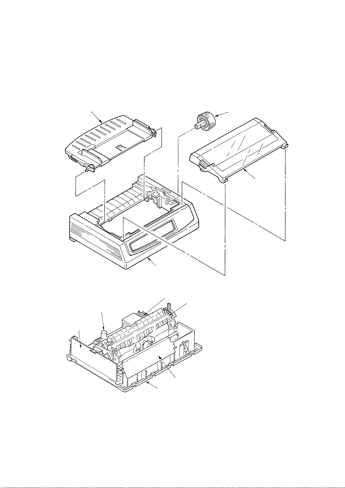
1.1. Standard Printer Configuration
This printer consists of the following assemblies:
Sheet guide assy
Platen knob
Access cover
assy
Upper cover
Control/Power supply assy
Driver board
Transformer assy
Pull-up roller assy
Operation panel assy
Main chassis assy
Figure 1-1 Configuration
1 – 1
Page 7
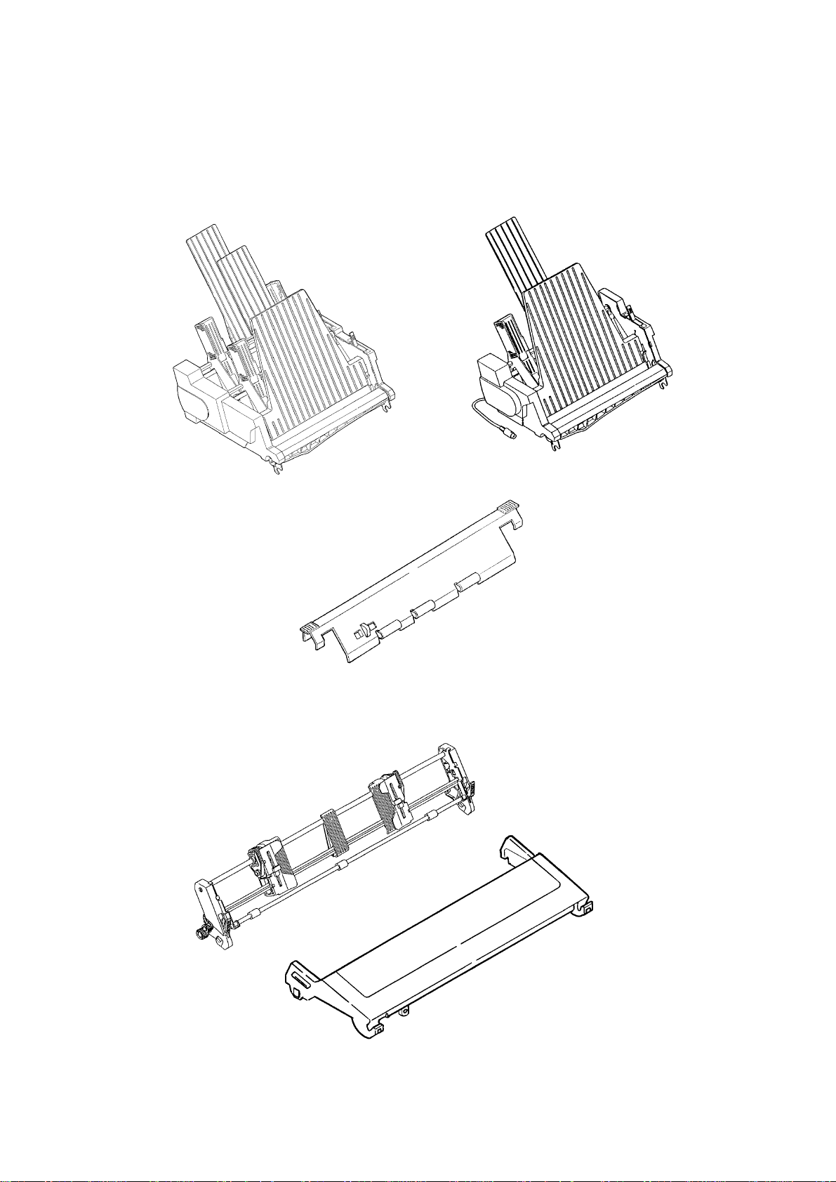
1.2 Options
(1) Cut sheet feeder unit (CSF)
(Narrow and wide versions available)
Dual-bin CSF Single-bin CSF
Attachment assy
(2) Pull-tractor assy
1 – 2
Page 8
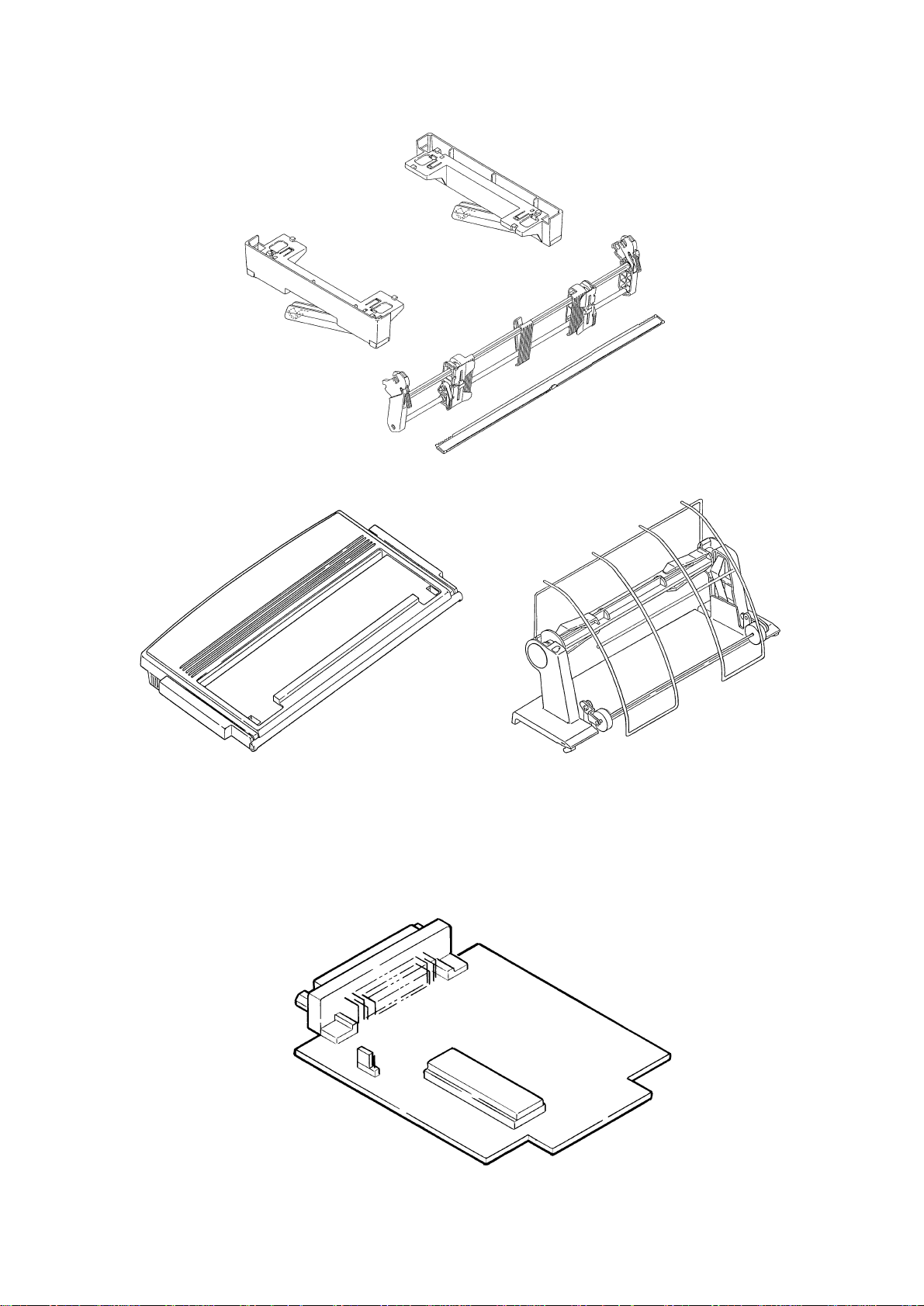
(3) Bottom push tractor unit
(4) Roll paper stand (Narrow only)
(5) Serial I/F
• RS232C
• RS422A
• Current Loop
1 – 3
Page 9

2. THEORY OF OPERATION
Page 10

2. THEORY OF OPERATION
2.1 Electrical Operation
The electrical operation of the printer circuit is described in this section.
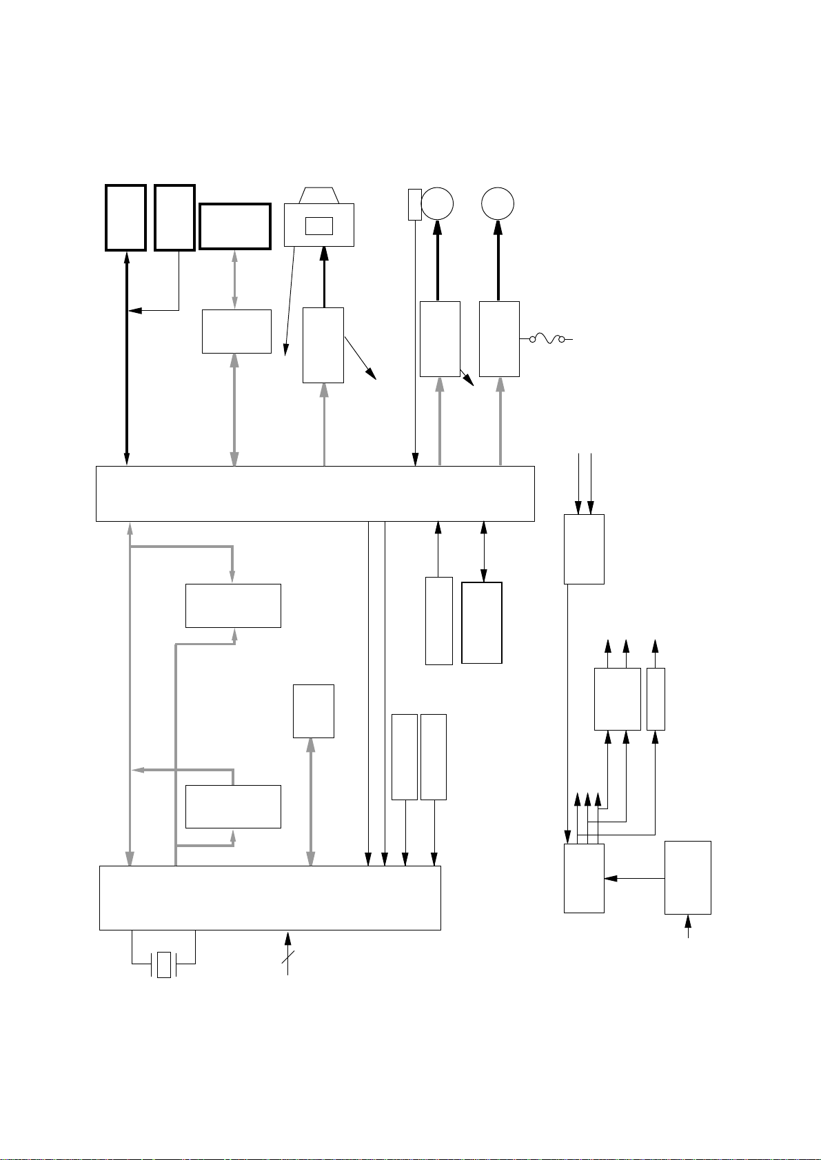
2.1.1 Summary
Fig. 2-1 shows the block diagram of the printer.
The control board is made up of the microprocessors, peripheral circuits, drive circuits, sensors
and interface connectors.
The power to the control board is supplied by the power board through the connector cord.
The power to other electrical parts is also distributed through the connectors within the control
board.
2.1.2 Microprocessor and the Peripheral Circuit
(1) Microprocessor (Q7: 67X640)
This processor is a CMOS single-chip computer with integrated peripheral device functions
and a 16 bit MPU core, all OKI original architecture.
The processor has a 20 bit address bus and a 16 bit data bus.
It is capable of accessing up to 1M word program memory and 1M bytes of data memory.
The following characteristics are also provided:
• Built-in type data memory of 512 bytes
• 8-bit 4-channel A/D converter × 1
• 16-bit automatic reload timer × 2
• 8-bit serial port × 2
• 8-bit parallel port × 3 (bitwise I/O specification available)
And others.
The function of this microprocessor is to provide a central mechanism for the entire printer
by executing the control program through the LSI and driver circuits.
2 – 1
Page 11
12.288
MHz
4
Vcc-Level
TSD
AUTO-LF
AI
INT
Release-SW
Bottom-Sensor
PE-SENSOR
OPERATION
PANEL
Serial
Rectifier
circuit
40 volt
8 volt
5 volt
Transformer
Reset
circuit
Print-IPT
I/F-IPT
EEPROM
1 Kbits
67 x 640
ADDRESS
ROM
AD-BUS
DRAM
4*64
Kbit*2
LSI
RESET
5VD
Vcc-Level
Fuse
40 V
LF
driver
SP
driver
SP alarm
HD-Alarm
Head
driver
2P Encoder
M
M
SP
LF
TSD
Para
-I/F
(opt.)
RS232C
-I/F
Roll paper
Stand
(opt.)
CSF
AC-input
1M
max
4M
16*256 Kbits
Alarm
circuit
Power-off
HD-Alarm
SP-Alarm
Divider
Figure 2-1
2 – 2
Page 12
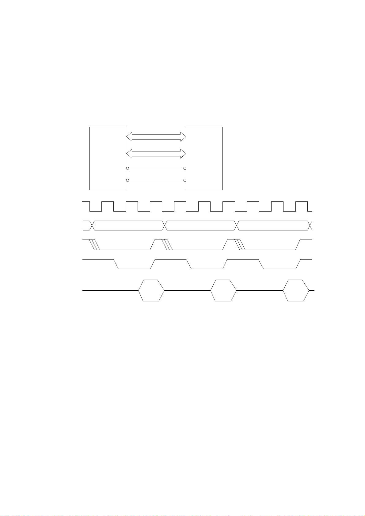
(2) Program ROM
This is a 256 × 16 bits (4M bit) [MAX] EPROM with the control program for the printer
stored. The MPU executes instructions under this program.
The program ROM is assigned to the program memory area of the MPU and is fetched
by the PSEN signal of the MPU.
The following shows the operation of the memory access.
MPU ROM
A0~A17
D0~D15
MPU CLOCK
A0~A17
PG-N
PSEN-N
D0~D15
CSO
PSEN
PG-N
Program Program Program
IN IN IN
CE
OE
2 – 3
Page 13
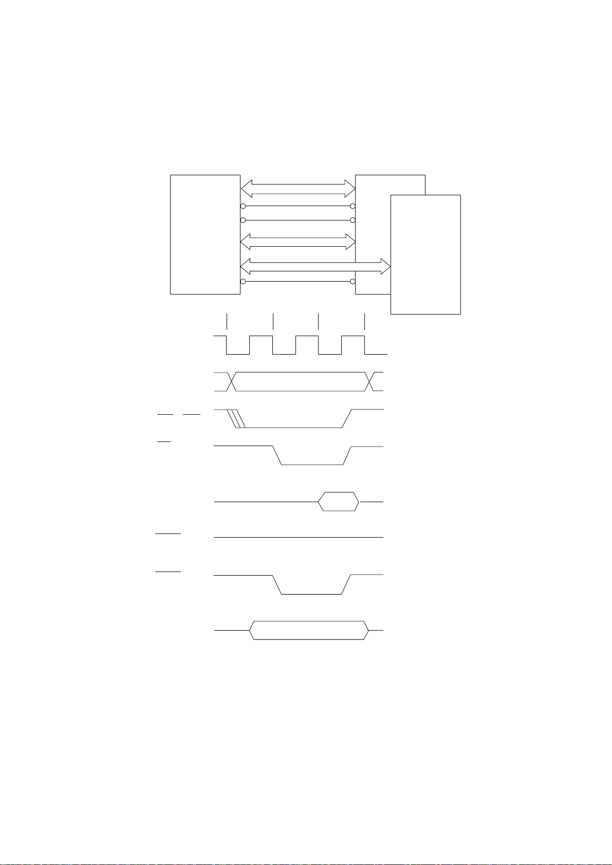
(3) RAM (MSM51C464A-80RS)
The RAM is CMOS dynamic RAM with (64K × 4-bit) × 2 configuration, and used as buffers
(such as receiving buffer, printing buffer, DLL buffer and working buffer).
The following shows the examples of the memory access operation.
RAM 1 (Q3)MPU
A0~A7
RAM 2 (Q4)
Clockout*
A0~A7
CS1~CS4
RD
D0~D7
(Read)
P03
CS1
RD
RAS
CAS
D0~D3
D4~D7
OE
T1 T2 T3
WRH
WRL
D0~D7
(Write)
8-bit bus, byte instruction
* Clockout is provided when the original excitation is selected.
2 – 4
Page 14
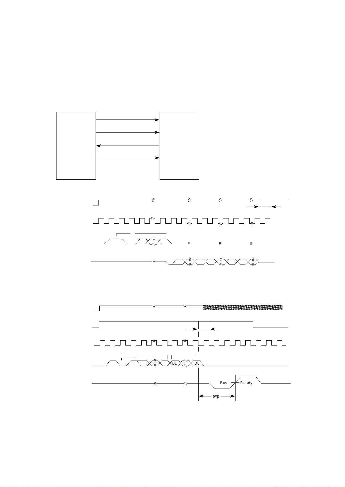
(4) EEPROM
The EEPROM is a CMOS serial I/O type memory which is capable of electrically erasing
and writing 1,024 bits.
The EEPROM contains menu data.
The following shows the memory access operation.
MPU EEPROM
EEDIN-P
P24
D1
EECS-P
P27
CS
EEDOUT-P
P25
DO
EECLK-P
P26
PRE = O
PE = X
SK
EECS-P
EECLK-P
EEDIN-P
EEDOUT-P
PRE = O
PE
EECS-P
EECLK-P
EEDIN-P
Start
code
Start
code
Operation
code
11
Operation
code
0
Address
0
A0A5
0
D15 D0 D15 D0 D15
Read cycle timing (READ)
Address Data
11
t
CS
t
CS
D0D15A0A5
EEDOUT-P
ReadyBus
twp
Write cycle timing (WRITE)
2 – 5
Page 15
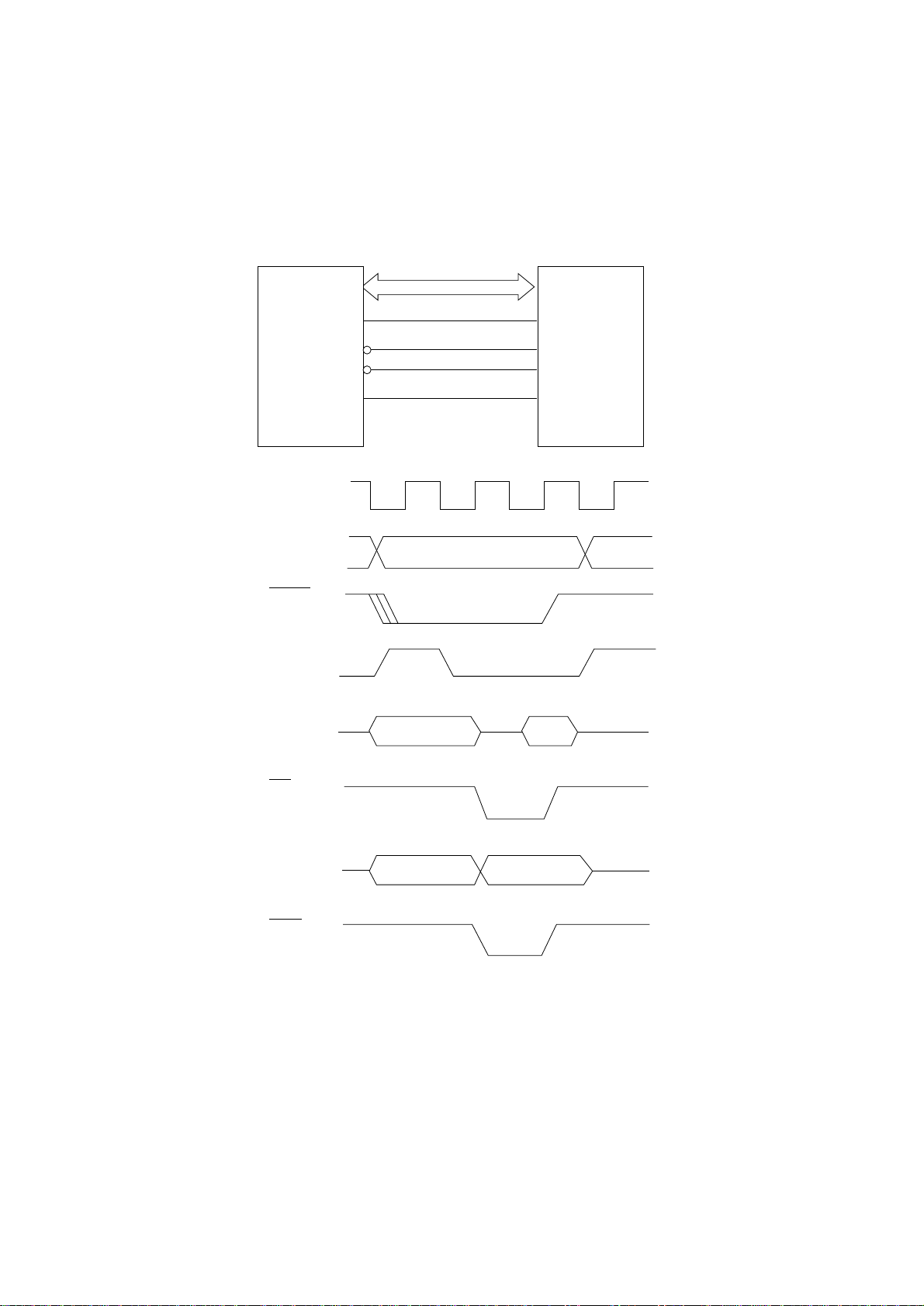
(5) LSI
This LSI detects and controls the SP motor speeds by monitoring the two phase sensor
signals obtained from the DC motors and modifying the excitation phases as appropriate.
This LSI is connected in multiplex to the MPU.
MPU
P07
RD
WRL
P01
Clockout*
A0~A19
LSICS
ALE
A/D bus
LSI
ALE
RDN
WRL
LSIC
D0~D15
(Read)
RD
D0~D15
(Write)
WRL
Address
Address
Data
Data
* Clockout is provided when the original
excitation is selected.
2 – 6
Page 16
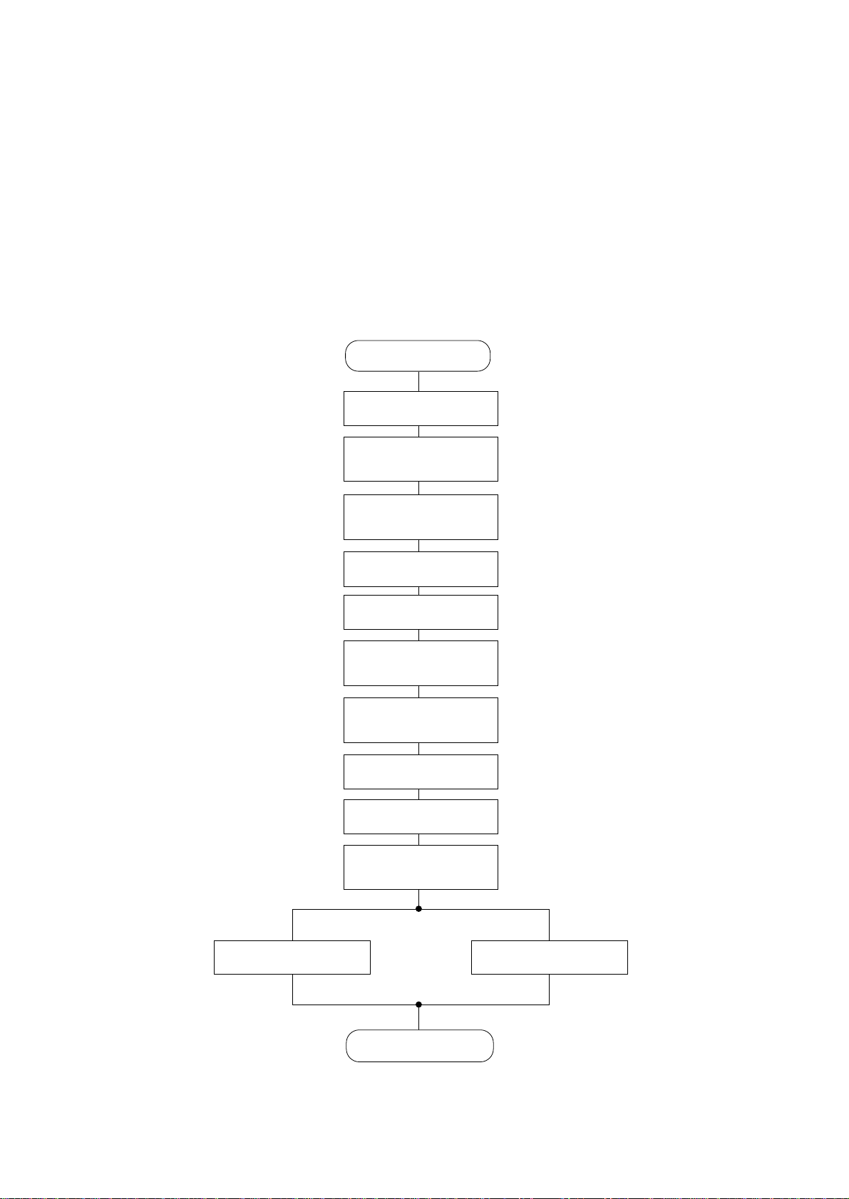
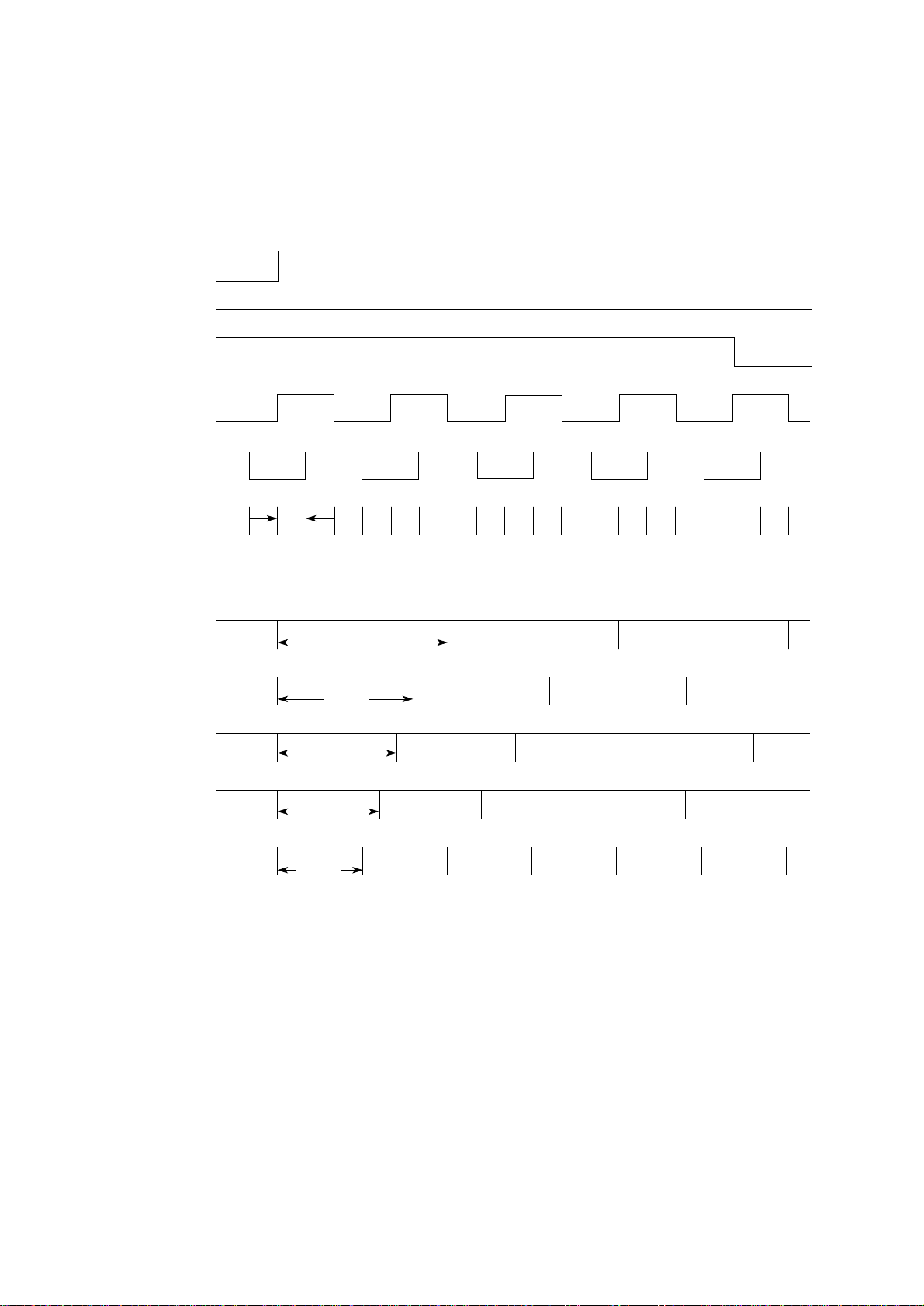
2.1.3 Initialization
This printer is initialized when the power is turned on or when the I-PRIME-N signal is input
from the host side via the parallel interface.
For the initialize operation, the RST-N signal is first output from the reset circuit to reset the
MPUs and LSIs. When resetting ends, the program starts and the LSIs are reset by MPU via
LSIRST-N. Reset operation by I-PRIME starts program to initialize, but does not reset the MPU.
The program here sets the mode of the LSI including the MPU, checks the memories (ROMs
and RAMs), then carries out carriage homing, and determines the LF motor phase.
Finally, the program establishes the interface signals (P-I/F: ACK-P signal sending, and S-I/F:
BUSY-N signal off) and lights the SELECT lamp to inform the ready state for receiving to the
host side and ends the initialize operation.
Start
MPU RESET
MPU
Initial Setting
Internal RAM
CHECK
Serial
I/F
I/F BUSY OFF
ROM CHECK
LSI RESET
External RAM
CHECK
LSI Initial Setting
and I/F Busy ON
RAM Clear
Carriage Homing
LF Motor Phase
Initialization
Parallel
I/F
I/F ACK Send
End
2 – 7
Page 17
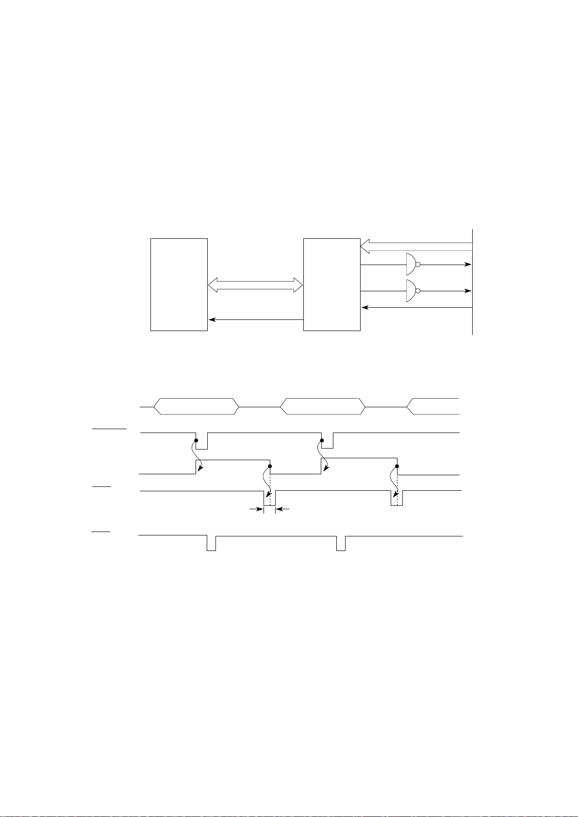
2.1.4 Parallel Interface Control
The parallel data input from the host to the interfaced LSI is latched to its internal register at
the falling edge of the STROBE-N signal.
At the same time, the LSI sets the BUSY signal to the high level to inform the host that the
data is being processed, and outputs the RXD signal to inform the MPU of data reception. The
data is read upon receiving the RD-N signal from the MPU.
When the data processing ends, the BUSY signal is set to off and the ACK-N signal in sent
to request the next data. When reception is impossible because the buffer is full, the BUSY signal
is sent to request stopping of data transmission.
MPU LSI
CN1
Receive Data
Data
1 to 8
STROBE
BUSY
ACK
RXD
A/D bus
RXD
P16 NRXD
500ns max.
2~8µs
NBSY
ACK
NSTB
BUSY
ACK-N
STB-N
2 – 8
Page 18
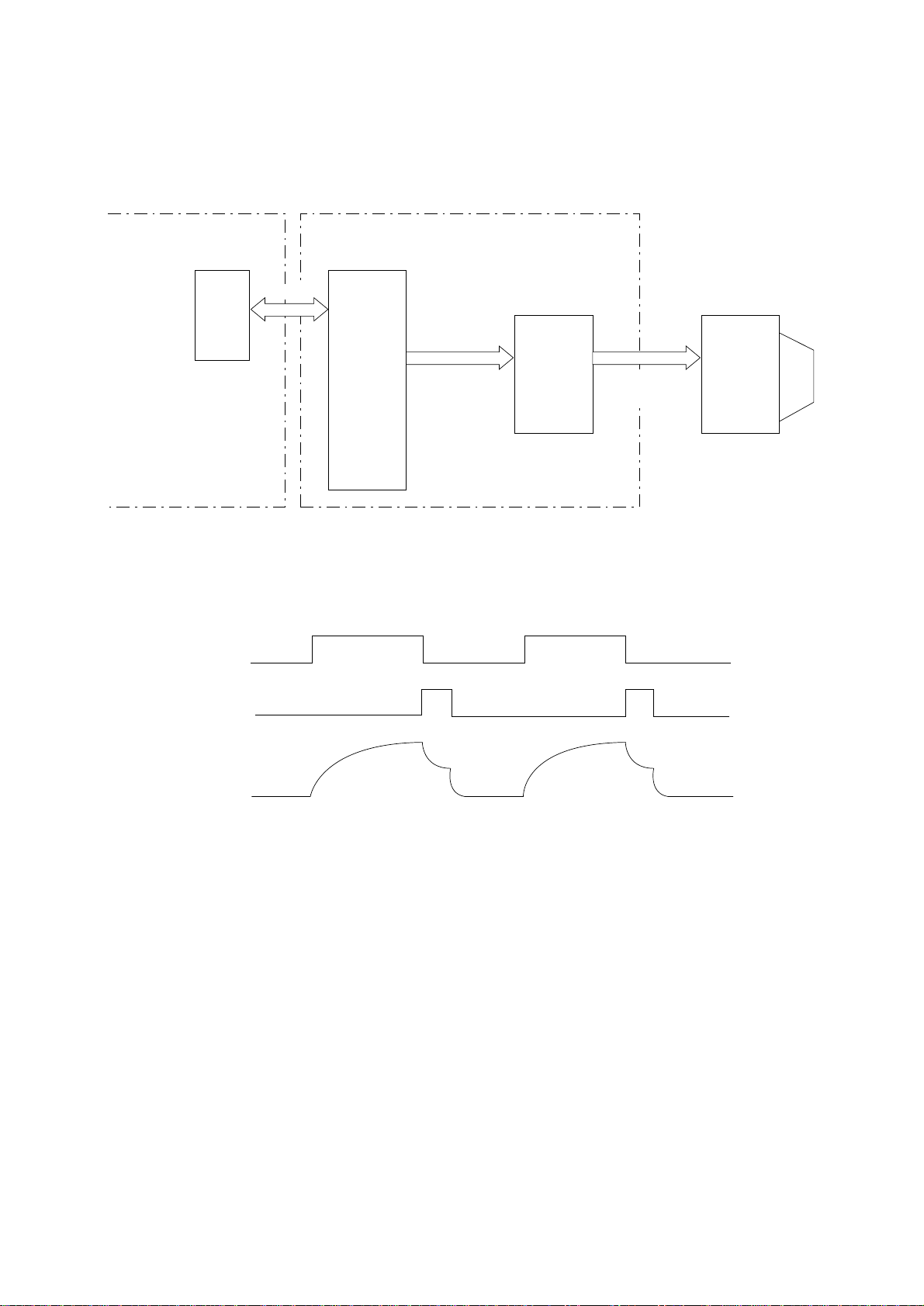
2.1.5 Print Control
Print data is transmitted as parallel data (HEAD1~HEAD9) from LSI to print head. LSI generates
print timing and drive time.
Control/Power Supply Board
MPU LSI
DT1
A/D bus
Driver Board
Print Data
HEAD1-N~
HEAD9-N
DRIVER
HEAD DRIVE TIMING CHART
Print Data
HEAD1~
HEAD9
Print Head
DT2
HEAD
DRIVE CURRENT
2 – 9
Page 19
Print Compensation Control
The print compensation can be made as shown below:
(a) Voltage compensation (See 2.1.8 “Alarm Circuit.”)
(b) Temperature compensation (See 2.1.8 “Alarm Circuit.”)
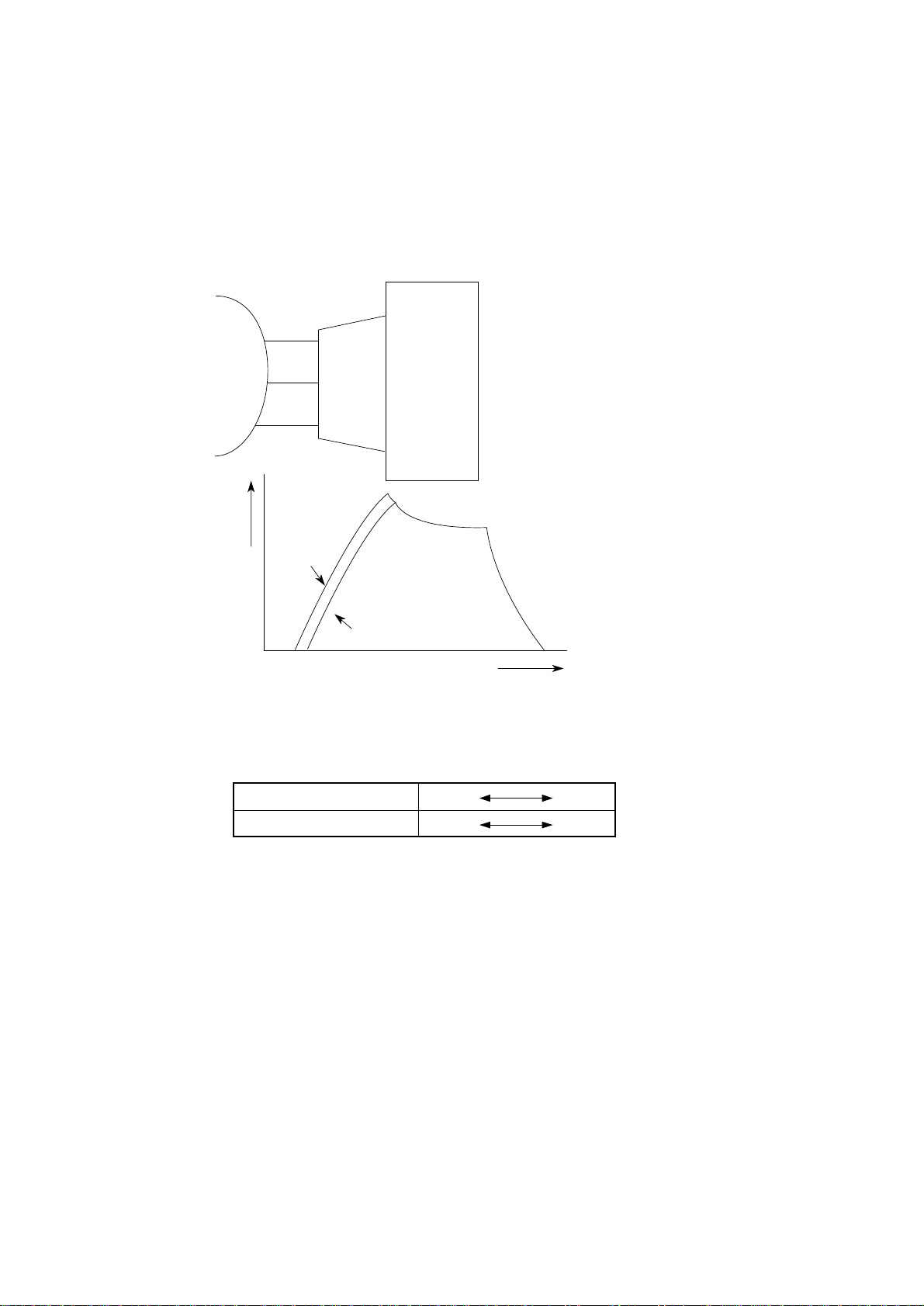
(c) Pin stroke compensation
Platen
Print Head
Pin 1, 2
As shown in the drawing left, the stroke length
up to the platen is different for each pin.
3~6
8, 9
Pin coil
current
Pin 1, 2,
8, 9
Pin 3~6
Time
(d) Simultaneous Compensation of the number of impact pins
The MPU is provided with the compensation table for each pin to make necessary
compensation.
Number of impact pins Few Many
Drive time Short Long
2 – 10
Page 20

(e) Print mode compensation
According to the thickness of the printing medium, the print mode is compensated
as shown in the table below:
Head Gap Range 1 2 3 4 5
Print speed 100% 95% 85% 85% 80%
Drive time Short Long
(Drive time lengthens at each step.)
2 – 11
Page 21
2.1.6 SP/LF Motor Control
(1) Space motor control
The SP motor driver (HA13412) drives the three-phase brushless motor based on the
phase signal (SPU, SPV and SPW) and the speed instruction data from the LSI. The MPU
can identify the current speed of the space motor by measuring through the LSI the pulse
length of the output (øA, øB) of the slit encoder included in the space motor.
By comparing the target speed for each print mode with the actual current speed to change
the speed instruction data, the motor speed is accelerated or decelerated to maintain the
specified speed for each print mode.
SPU
SPV
SPW
SP truth table
HALL AMP INPUT OUTPUT
SPU SPV SPW U V W
H H L OPEN L H
H L L L OPEN H
H L H L H OPEN
L L H OPEN H L
L H H H OPEN L
L H L H L OPEN
2 – 12
Page 22
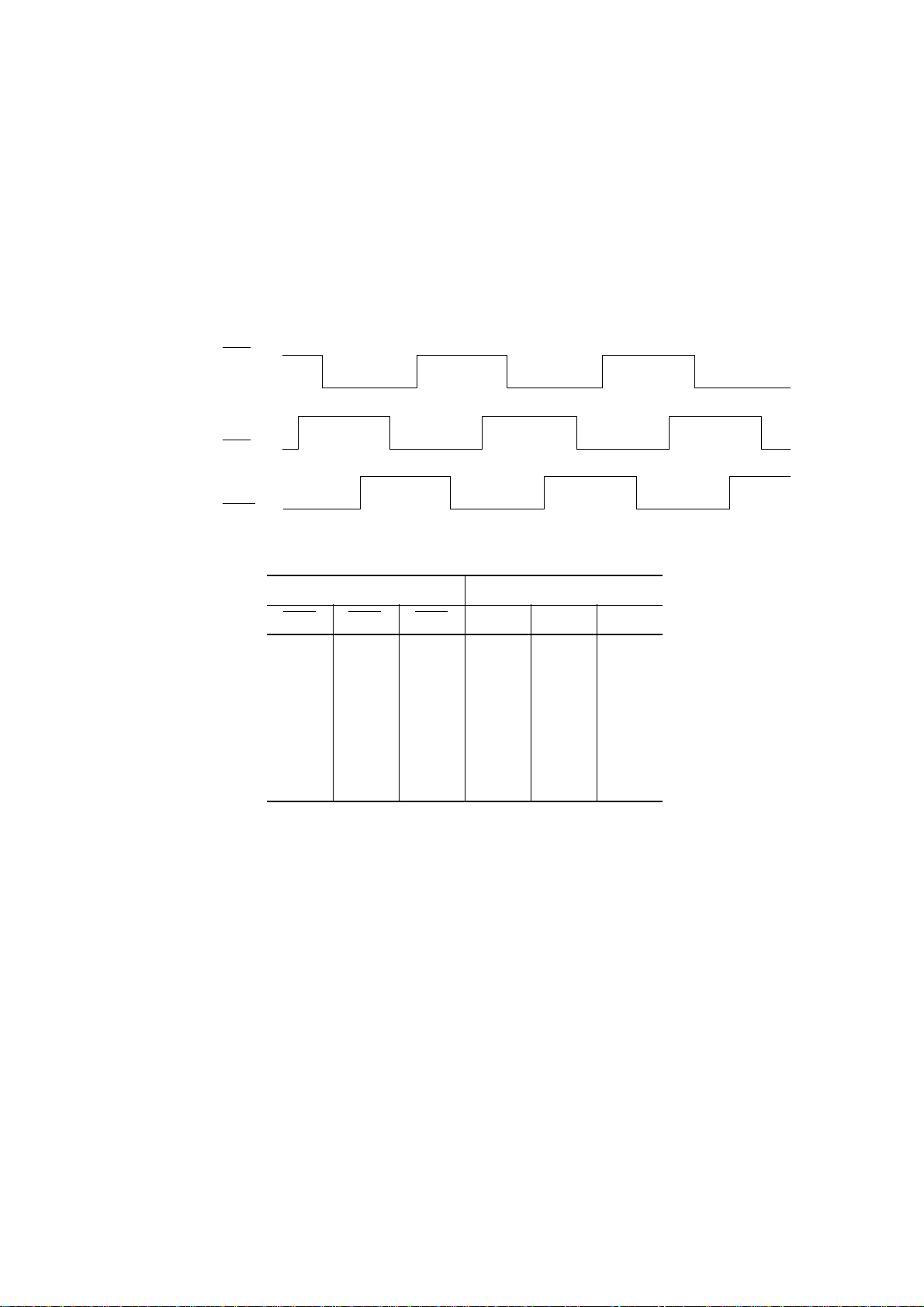
(2) Encoder disk
In the operation of the spacing motor, the PHASE-A and PHASE-B signals are generated
when the encoder disk interrupts the photo sensor.
The LSI divides these edge pulse signals in accordance with the print pitch, and sends
the IPT signal to provide dot-on timing and carriage position detection timing.
SPU
SPV
SPW
PHASE-A
PHASE-B
1/720"
IPT 10 CPI
IPT 12 CPI
IPT 15 CPI
IPT 17 CPI
IPT 20 CPI
• UTILITY MODE
1/120"
1/144"
1/180"
1/206"
1/240"
2 – 13
Page 23

(3) LF motor control
The LF motor driver (MTD2005F) drives the LF motor in two-phase or 1-2 phase bipolar,
based on the phase changeover data and the output current data from the LSI.
The data from the LSI is processed by a specific register contained in the LF motor driver
to measure the overdrive time and to change the phase.
PHASE-A
PHASE-B
[FORWARD]
[REVERSE]
2 – 14
Page 24

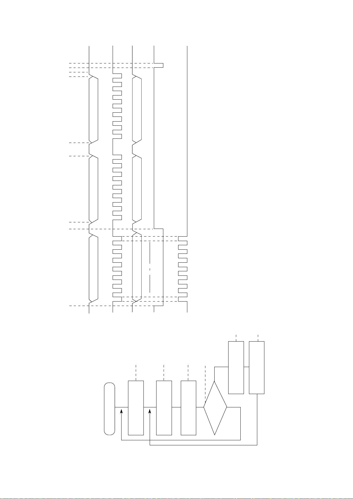
2.1.7 Operation Panel
The clock synchronization OPCLK of LSI is used to input the switch data and output the LED
data through the operation panel control LSI (IC1: BU5148S).
LSI
OPTD
OPCK
NPA2
OPRD
OPTXD
77
OPCLK
78
OPCLR-N
80
OPRXD
79
Command
and Data
latch
LED driver
+5V
Switch
controller
A 2-byte (15 bits + 1 even parity bit) command (OPTXD) is transmitted to the LSI (BU5148S)
in synchronization with the OPCLK signal. The LSI decodes this command and when it is found
to be legal, returns a 2-byte command response back to the LSI which includes data on Switch
information, LED status, receive command ACK/NAK and 1 odd parity bit.
Any transmission errors found cause the command to be reissued after the transmission of the
OPCLR-N signal.
2 – 15
Page 25
8
or
5
6
7
3 1
Command (second)
Command response (second)
Note
Command (first)
Command response (first)
bit0 bit7
bit0 bit7
1 2 3 2
OPTXD
OPCLK
OPRXD
1
OPCLR-N
2
Reset
within
3
BU5148S
4
NO
7
Error notification
8
Instruction for
retransmission
the bit 0 to bit 3 of OPRXD are fixed so that the response can be returned before decoding the command.
YES
for OK or NG
Response check
Note: From the illustration above, you can see that the command and the command response are output at the same time. This is because
5
6
Power ON
reset
Write instruction for LSI
etc.
LSI write for LED data,
data read
Read instruction for
2 – 16
Page 26
2.1.8 Alarm Circuit
(1) Head drive time alarm circuit
This circuit monitors the drive time using the HDALM signal interlocked with the overdrive
signal of each drive circuit.
If the drive time of any drive circuit exceeds the specified time, the drive fault alarm circuit
sends an ALARM-N signal to turn on the SCR (SO).
This cause the secondary coil (40V) of the transformer to be short-circuited, causing an
overcurrent to flow through the primary coil and making the AC fuse (transformer assy)
open.
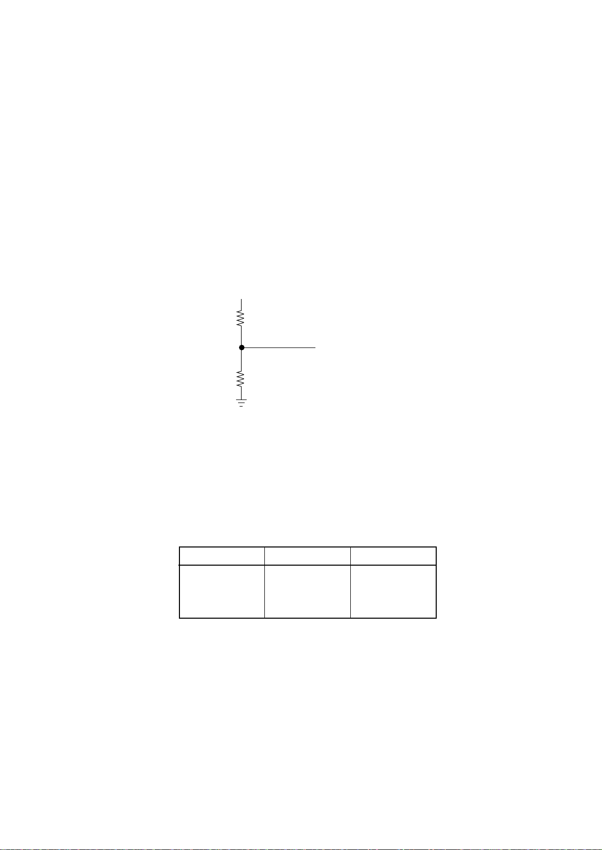
(2) Alarm processing when DC power is low.
+ 40V is converted into the POWLEV signal (0V to +5V) by R28 and R29 and input into
the A/D port of the MPU to control the drive time and the print speed (pass number) of
the head.
+40V
R28
POWLEV
R29
(a) Head drive time
The head drive time is lengthened to compensate for the amount of voltage drop by
monitoring the POWLEV signal once every 500 µ sec. to control and maintain the
impact necessary for each printing pin at the fixed value.
(b) Print speed
Voltage, +40V Pass number Print speed
38V or more 1 Pass 100%
25V to 37V 1 Pass 100~30%
25V or less 1 Pass 30%
2 – 17
Page 27
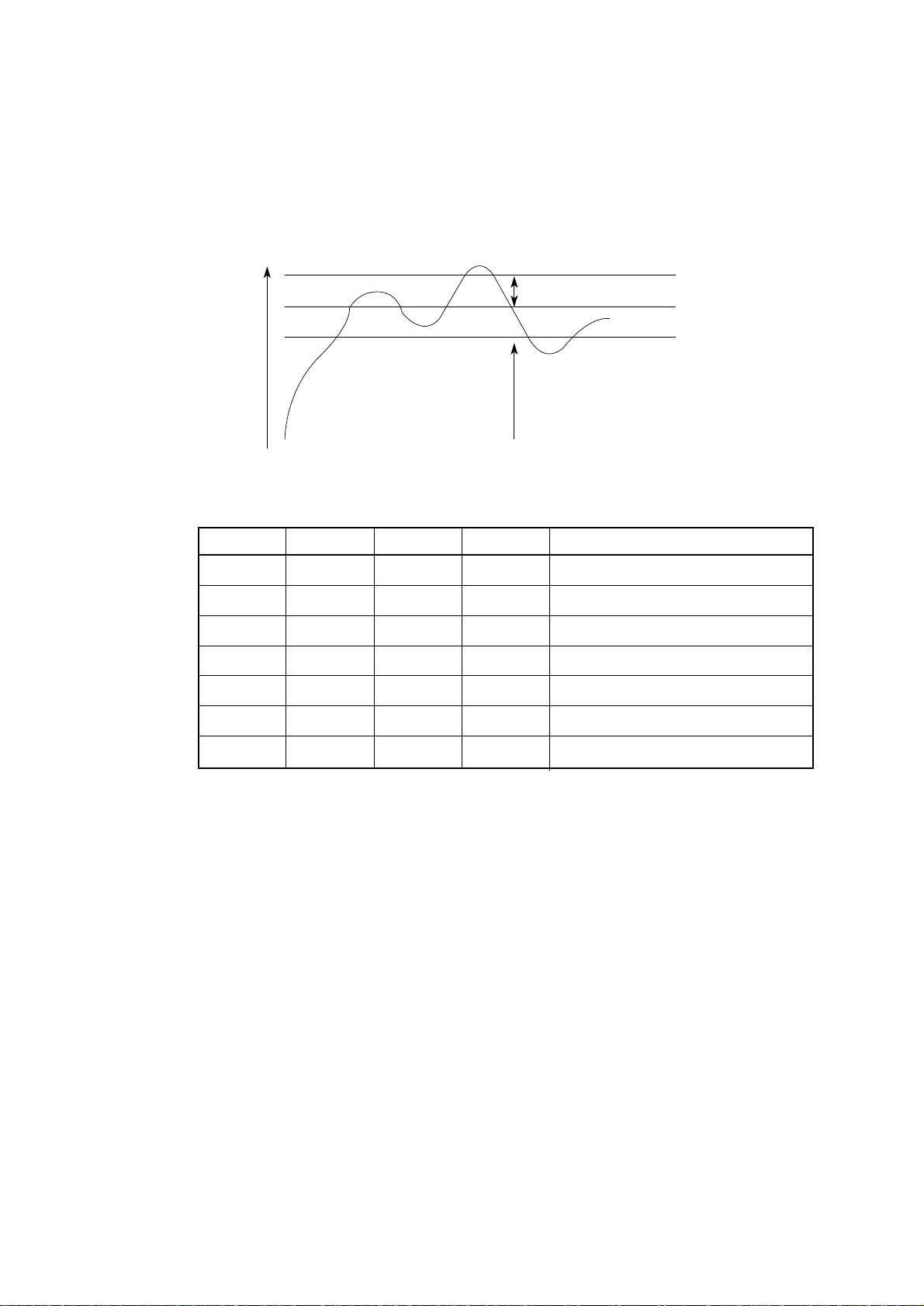
(3) Head overheat alarm
The voltage of the output TSD signal of the thermistors, one of which is contained in the
print head and the other in the print head driver, is monitored by the CPU/AD port to control
the voltage
Temp
Mode and print control
Mode Speed Pass Direction
1 100% 1 Bi
2 85% 1 Bi
3 70% 1 Bi
4 55% 1 Bi
5 40% 1 Bi
Stop
119°C
Mode up
α°C
ß°C
Mode down
6 30% 1 Bi 1.5 Sec Stop
(7) Stop
• When the temperature is between α°C and 119°C, the mode switches sequentially to
higher level. When the temperature falls below ß°C, the mode switches to lower level.
• When the temperature exceeds 119°C, printing will stop.
• When temperature gradient is steep, higher mode shall be specified directly.
2 – 18
Page 28
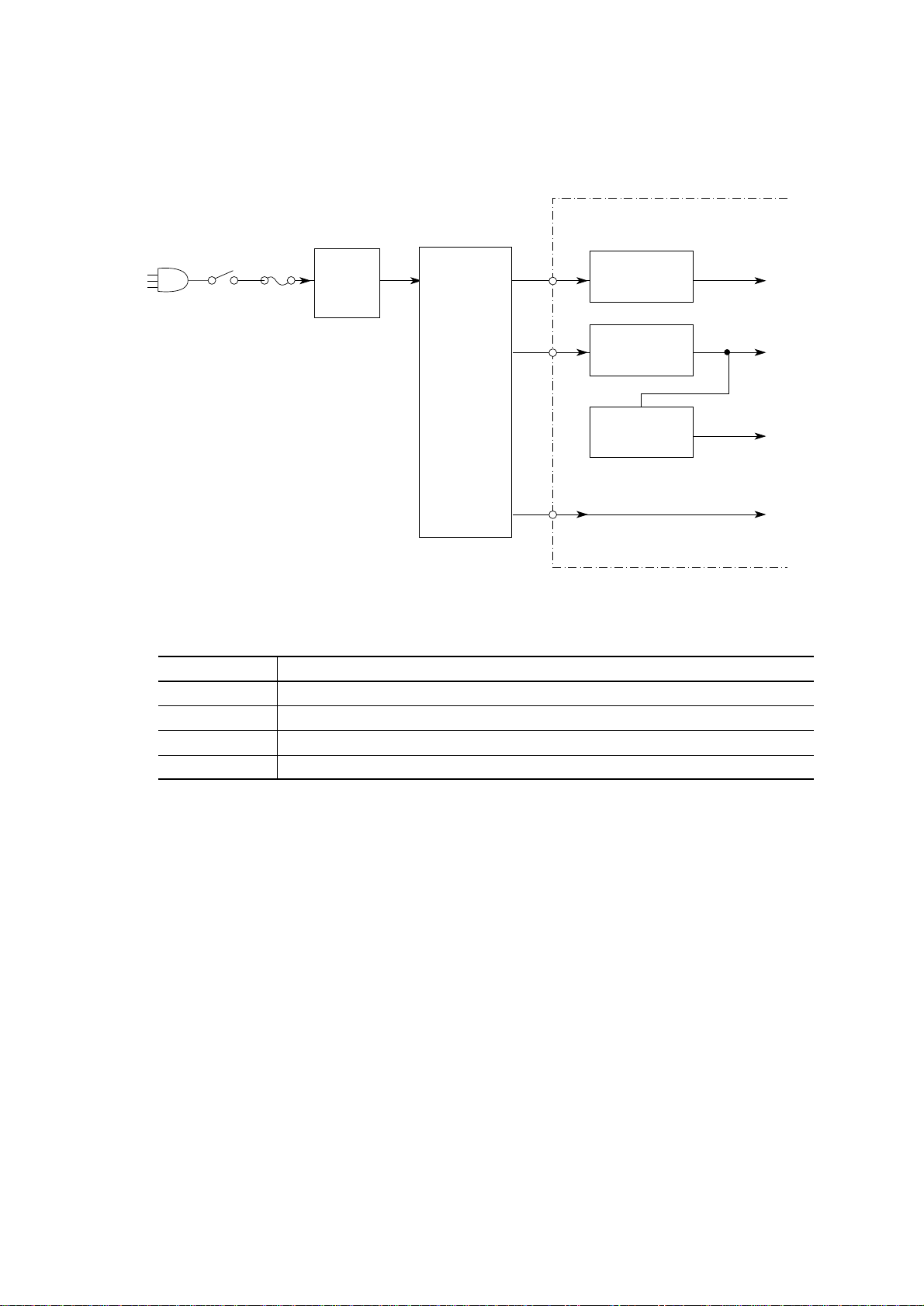
2.1.9 Power Supply Circuit
This power supply circuit supplies the +5VDC, +8VDC, +40VDC, 10VAC.
Control Board
SW
Fuse
Noise
filter
circuit
Transformer
The uses of output voltages and signals are described below.
Voltage/signal Use
+5V Logic IC/LED drive voltage
+8V Serial interface line voltage and SP motor driver
+ 40V Printhead, LF motor drive voltage, SP motor drive voltage
AC 10V Option board
Rectifier
Rectifier
Regulation
Circuit
+40V
+8V
+5V
AC10V
2 – 19
Page 29
2.2 Mechanical Operation
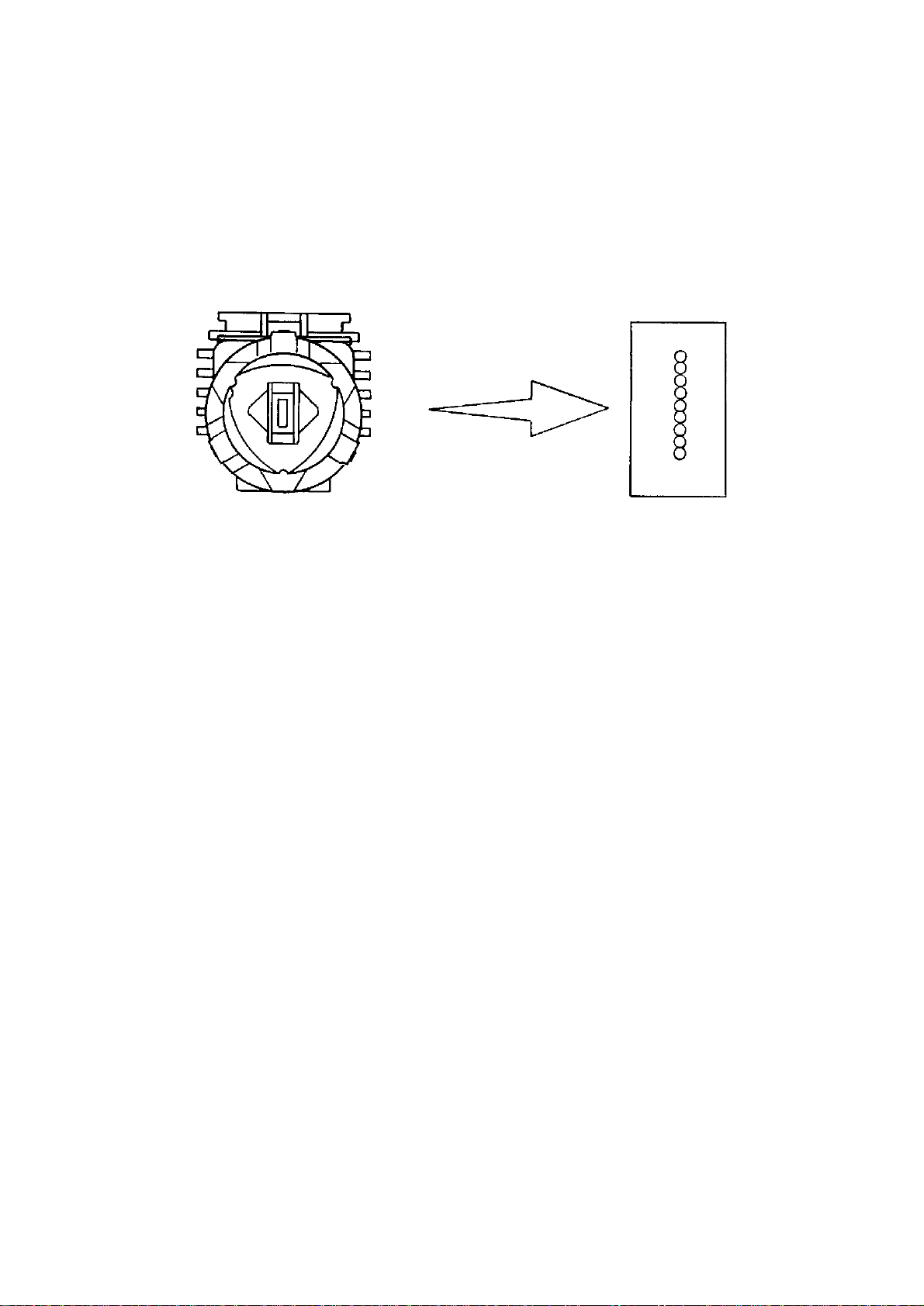
2.2.1 Printhead Mechanism and Operation (See Figure 2-2.)
The printhead is a spring charged 9-pin driving head using a permanent magnet. It is attached
to the carriage, which moves in parallel with the platen. Electrically, this unit is connected to
the control circuits through the control board.
Figure 2-2 Arrangement of the head pins
View from the tip of the printhead
(1) The printhead configuration:
The printhead is composed of the following parts:
(a) Wire guide
(b) Spring assembly (Wire, Armature, Spring, Yoke, Spacer)
(c) Magnet assembly (Magnet, core, coil, Yoke)
(d) Printed circuit board
(e) Fin
2 – 20
Page 30

(2) Operation of printhead (See Figure 2-3.)
(a) When the printhead is idle, the armature is attracted by a permanent magnet and
the spring fixing the armature is compressed. The print wires fixed to each armature
are thus concealed under the wire guide.
(b) When a signal for a character to be printed is detected, a current flows through the
coil. When the coil is activated, the magnetic flux (caused by the permanent magnet
between the armature and the core) is canceled to eliminate the attraction force. The
armature is driven in the direction of the platen by the force of the armature spring.
The print wire fixed to the armature protrudes from the tip of the wire guide, strikes
the paper through the ribbon and prints a dot on the paper.
(c) After the character has been printed, the armature is magnetically attracted again
and the print wires are again concealed under the wire guide.
A thermistor in the printhead prevents burning caused by over-heating of the coil
during extended continuous bi-directional printing. When the temperature of the coil
exceeds a pre-determined limit (about 119°C) the control circuit detects a thermistor
signal. Printing will then be intermittent or stop completely until the coil temperature
falls below the limit value.
2 – 21
Page 31

Paper
(1) When printing
Platen
Paper
Print wire
Printhead
Armature assembly
Thermistor
Print wire
(2) When not printing
Wire guide
Paper
Figure 2-3
Yoke
Spacer
Magnet assembly
2 – 22
Page 32

2.2.2 Spacing Operation (See Figure 2-4.)
The spacing mechanism consists of a carriage shaft mounted in parallel with the platen, and
a carriage frame that moves along the shaft. It is driven by a DC motor mounted on the bottom
of the carriage frame. Items included in the spacing mechanism are as follows:
(a) DC motor with motor gear
(b) Carriage frame (stationary yoke and motor driver board included)
(c) Carriage shaft
(d) Space rack
(e) Sensor
(f) Encoder disk
(1) Spacing operation
The carriage frame, on which the printhead and space motor are mounted, moves along
the carriage shaft in parallel with the platen. When the spacing motor rotates
counterclockwise, the driving force is transmitted to the motor gear. As the motor gear
rotates, the carriage moves from left to right.
Mechanically, it is designed in such a way that for every revolution of the DC motor, the
carriage frame moves 0.8 inch (20.32 mm).
At the same time the encoder disk rotates together with the motor and passes the sensor.
The position of the carriage frame can be determined by counting the interrupts detected
by the sensor.
In the same way, the rotation of the space motor can be recognized and controlled by
measuring the cycle of interrupts detected by the sensor.
2 – 23
Page 33
Carriage frame
Print Head
Carriage shaft
Space rack
Encoder disk
Encoder sensor
Motor gear
Slider
Figure 2-4
Guide rail
2 – 24
Page 34

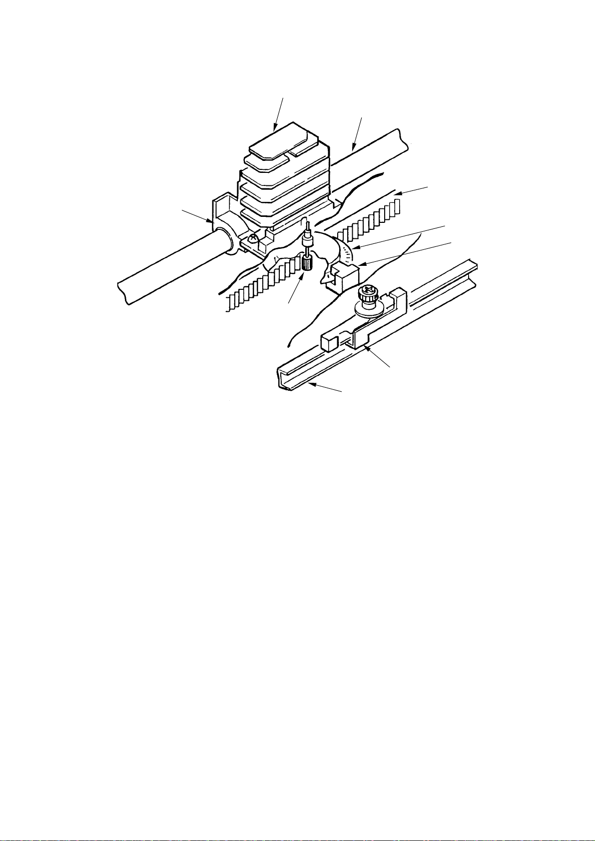
2.2.3 Head Gap Adjusting (See Figure 2-5.)
The head gap adjusting lever moves back and forth to tilt the carriage frame, altering the gap
between the printhead and the platen.
The adjusting screw, which is connected to the adjusting gear rotates when the adjusting lever
is moved creating a fine gap adjustment. If the adjusting gear is pushed down, the adjusting
screw can be turned with a screw driver to change the coarse gap adjustment.
When the adjusting lever is set to range ➁ ~ ➄ the contact which is attached to the under side
of the carriage cover will connect with the contact of the space motor PC board. The printer
will reduce the printing speed automatically to ensure that adequate printing pressure is maintained
for multipart paper.
And, the adjusting cam adjusts the headgap toward left and right side in accordance with the
guide rail up and down as a position of the left end of it.
2 – 25
Page 35

Range
Platen
1
2
3
Adjusting lever
Range from 5 to 1
Adjusting screw
Adjusting cam
4
5
Idler gear
C.C.W.
Carriage shaft
Printhead
Adjusting screw
Adjusting gear
Narrows
Printhead
Platen
Range from 1 to 5
Guide rail
Widens
C.W.
Figure 2-5
2 – 26
Page 36

2.2.4 Ribbon Drive (See Figure 2-6.)
The ribbon driver mechanism moves the ribbon in synchronization with the space motor operation.
The ribbon drive mechanism consist of the following items:
(a) Ribbon drive gear assembly
(b) Ribbon gear (space motor)
(c) Ribbon cartridge
(1) Ribbon cartridge
An endless ribbon with a single direction feed is used. Ink is supplied from an ink tank,
which is built in to the ribbon cartridge.
(2) Ribbon feed operation
When the space motor is activated, the ribbon gear rotates. The rotation is transmitted
via the ribbon drive gear assembly to the drive gear in the ribbon cartridge, thus moving
the ribbon.
The feed direction of the ribbon is maintained by switching the rotational direction of the
gears in the ribbon drive gear assembly. This ensures ribbon movement when bidirectional
printing is used.
2 – 27
Page 37

Ribbon cartridge
Drive gear
Ink tank
Figure 2-6
2 – 28
Page 38

2.2.5 Paper Feed Operation
Feeding of the paper is performed by turning the platen and the pin tractor, which is driven by
the LF pulse motor.
Item of the paper feed mechanism are as follows:
(a) Pulse motor with gears
(b) Decelerating gear
(c) Platen
(d) Tractor feed unit
(e) Pressure roller
2 – 29
Page 39

(1) Cut sheet and continuous sheet switching mechanism (See Figure 2-8.)
Three different paper paths can be selected and set by the change lever.
(a) TOP (for cut sheet)
When the cut sheet is used in the manual mode or fed by the CSF (option), set the
change lever at the position marked TOP.
[Operation]
The driving force of the platen gear (R) is transmitted to the idle gear by setting the
change lever to the TOP position. However, this causes the idle gear to be disengaged
from the change gear, leaving it free.
At this time, the pressure rollers (at the rear and the front) are pressed securely to
the platen to feed the cut sheet. At the same time, the switch lever positions between
the rear switch and bottom switch, to confirm to the control board that you are in the
cut sheet mode.
In the cut sheet mode, the control board automatically feeds the sheet up to the print
start position after pausing for the wait time stored in the menu.
(b) REAR (Continuous sheet from push tractor)
When the change lever is set to REAR position, the change gear is engaged with
the idle gear and the tractor gear to transmit the rotation of the platen to the push
tractor shaft, and the continuous sheet is fed from the push tractor.
At the same time, the switch lever turns on the rear switch, to confirm to the control
board that you are in the continuous sheet mode.
2 – 30
Page 40

(c) BOTTOM (Continuous sheet from bottom feeder) (option)
When the change lever is set in the BOTTOM position, the rotation of the platen
is transmitted to the drive gear of the bottom tractor feed unit through the idle gear
to feed the sheet which has been set in the bottom tractor feed.
At the same time, the switch lever turns on the bottom switch, to confirm to the control
board that you are in the continuous sheet mode.
Correlation in Mechanism
Mechanism
Lever
Position
TOP
REAR
BOTTOM
Rear
Switch
OFF
ON
OFF
Bottom
Switch
OFF
OFF
ON
Idle
Gear
Rotate
Rotate
Rotate
Change
Gear
Stop
Rotate
Rotate
Tractor
Gear
Stop
Rotate
Stop
Sheet
Insertion
Manual/
automatic
CSF:
Operation SW
or instruction
•
Operation
SW
or
•
instruction
•
Operation
SW
or
•
instruction
2 – 31
Page 41

Control Power
supply Assy
Bottom switch
Switch lever
Change gear shaft
Rear switch
Change lever
Release shaft
Change arm
TOP
Platen gear (R)
Platen
BOTTOM
Change lever
REAR
Tractor gear
Change gear
Reset spring
Idle gear
(Bottom tractor unit)
Figure 2-8
2 – 32
Page 42

(2) Cut-sheet feeder operation (See Figure 2-9.)
The pulse motor used for the paper feed mechanism is mounted on the left of the frame,
and the rotation of the motor is transmitted through decelerating gears (LF idle gear, platen
gear) to the platen. When using cut-sheet paper, the change lever must be in the TOP
position to grab the paper, while disengaging the push tractor.
When the change lever is set to the TOP position, the cut sheet is automatically fed
in up to the print start position after pausing for the wait time stored in the menu.
Stepping motor
(LF motor)
Pressure roller
Platen
Platen gear
LF Idel gear
Figure 2-9
2 – 33
Page 43

(3) Continuous paper feed operation (Rear) (See Figure 2-10.)
The force transmitted to the platen, rotates the tractor gear through platen gear, the idler
gear and the change gear. The rotation of the tractor gear makes the pin tractor belt rotate
through a sheet feeder shaft, feeding the continuous paper.
Paper
Idle gear
Figure 2-10
Platen gear
Tractor gear
Change gear
2 – 34
Page 44

(4) Push and pull tractor mechanism (Option) (See Figure 2-11).
This mechanism consist of an optional pull tractor and a standard push tractor mechanism.
This mechanism can perform forward and reverse feed by setting continuous sheets to
the push tractor and pull tractor.
The rotation of the platen is transmitted to the push tractor and the pull tractor. Sheets
are fed by these two tractors at the same time.
To remove slack from the sheets, set the sheets according to the following procedure when
using the push and pull tractors.
1 Set the change lever to the REAR position (setting the sheets to the push tractor
to feed).
2 Set the paper, which is fed in front of the platen, to the pull tractor.
3 Set the change lever to the TOP position and feed paper using the platen knob.
4 If paper slack is removed, set the change lever to the REAR position.
Pull tractor
Drive gear
Platen gear
Idle gear
Push tractor
Platen
Figure 2-11
2 – 35
Page 45

(5) Pull tractor mechanism (option) (See Figure 2-12.)
Bottom feed of continuous sheets is possible only when an optional pull tractor unit is
installed.
The rotation of the platen is transmitted to the idle gear of the pull tractor unit through
the platen gear at the left end of the platen. The rotation of the idle gear is transmitted
to the drive gear, and continuous sheet forms are fed by the pull tractor being rotated
through the sheet feeder shaft.
Continuous sheet form
Pull
Tractor assembly
Sheet feeder shaft
Drive gear
Idle gear
LF motor
Platen
Platen gear
LF Idle gear
Figure 2-12
2 – 36
Page 46

(6) Bottom push feed operation (Option) (See Figure 2-13.)
The bottom push feed of the continuous sheet is possible only when the bottom tractor
feed unit is installed.
When the platen rotates, the rotational force of the platen is transmitted through the tractor
idle gear and the tractor change gear to the tractor drive gear of the bottom push tractor,
and the sheet of paper is fed in to the print start position.
Platen
Platen gear
Figure 2-13
Change gear
Idle gear
Tractor change gear
Tractor idle gear
Tractor drive gear
2 – 37
Page 47

(7) Paper clamp mechanism (See Figure 2-14.)
When setting the change lever to the BOTTOM , TOP or REAR position, the operation
of the front release gear arm changes according to the position of the release cam. And
at the same time, the position of the cam installed to the front release gear shaft changes,
and the open and close of the pressure roller.
Position of
change lever
BOTTOM OPEN OPEN
TOP CLOSE CLOSE
REAR OPEN OPEN
Open or close of
front pressure roller
Open or close of
rear pressure roller
2 – 38
Page 48

TOP
BOTTOM
Change lever
Release cam
Platen
Front release
gear arm
REAR
Figure 2-14
2 – 39
Page 49

2.2.6 Paper Detection Mechanism (See Figure 2-15.)
(1) Cut sheet detection
When the cut sheet is inserted, the point A is pushed backward and the paper near end
lever B rotates counter clockwise (CCW).
At this time, the rear sensor lever rotates counterclockwise (CCW), the rear sensor lever
and pulls out of the rear and top paper end sensor to detect that the sheet is provided.
The procedure for the paper end is made in the reverse order, that is, its detection is
performed when the paper end sensor is blocked.
(2) Rear feed detection
When the sheet is fed from the push tractor, the point B is pushed to the front side and
the paper near end lever A rotates clockwise (CW). At this time, the rear sensor lever
rotates counterclockwise (CCW), and pulls out of the rear and top paper end sensor to
detect that the sheet is provided.
The procedure for the paper end is made in the reverse order, that is, its detection is
performed when the rear sensor lever intercepts the sensor.
(3) Bottom feed detection
When the sheet is fed from the bottom, the point C rotates clockwise (CW). When the
bottom sensor lever rotates clockwise (CW), it pulls out of the bottom paper end sensor
to detect that the sheet is provided.
The procedure for the paper end is made in the reverse order, that is, its detection is
performed when the bottom sensor lever intercepts the sensor.
2 – 40
Page 50

Paper end sensor
Shaded portion
Sensor lever
A
Paper end lever
B
Bottom paper end lever
Figure 2-15
2 – 41
Page 51

(4) Top line print mechanism (See Figure 2-16.)
The front edge of the sheet is protected by the ribbon protector so that it can stop at a
position just near to the print head (0 tear off position) to start printing at the front end
of the sheet, without causing the sheet to crumple or curl up.
The printing starts at the front end of the sheet, and continues uni-directionally until the
front end of the sheet gets to the inside of the pull up roller cover.
After that, that printing continues bi-directionally.
2 – 42
Page 52

Ribbon protector
Platen
Printhead
Carriage frame assembly
Figure 2-16
2 – 43
Page 53

2.2.7 Automatic Sheet Feed
This function is used to feed in the sheet automatically up to the print start position when the
cut sheet or the continuous sheet is used.
[Operational procedure]
(1) When using the cut sheet
1) Set the change lever to the TOP position. (See Figure 2-17.)
2) Insert a sheet of paper between the platen and the paper shoot.
3) After the lapse of time selected by the “wait time” in the menu, the LF motor starts
its operation to feed the sheet of paper up to the print position.
4) When the default is selected, the sheet of paper is feed in up to the position 0.35
inches (first dot position) from the upper end of the sheet. However, the 0 tear off
mechanism allows the printing at the front end of the sheet by changing the TOF
position.
Sheet setting
REAR
PE
Detection timer
LF action
BOTTOMTOP
Time selected
on the menu
Time out
BOTTOM
SW2
TOP
SW1
REAR
Figure 2-17
2 – 44
Page 54

(2) When using the continouos paper
1) Set the change lever either to the rear side or the bottom side position. (See Figure
2-17.)
2) Set a sheet of paper either to the push tractor or the bottom tractor.
3) Press the “FF/LOAD” switch.
4) The LF motor starts its operation to feed the paper up to the print start position.
5) The paper is fed in up to the TOF position (Factory default: 0.35 inches from the top).
Push down the “FF/LOAD” switch.
Detection of the sheet supplied
PE
LF action
Line feed (about 3 inches) until the
detection of the sheet supplied
When the “”FF/LOAD” switch is pushed down, the LF motor feeds in the sheet about 3
inches. When the LF motor completes the operation and the sheet has not been fed in,
the feeding operating operation becomes, ineffective, thus resulting in the feeding jam.
2 – 45
Page 55

2.2.8 Paper Park Function (Continuous paper)
Continuous sheets which have been inserted can be reversed automatically by using the “PARK”
button on the operation panel.
1) Press the “PARK” button on the operation panel.
2) Reverse LF is started and paper is fed in reverse until paper end occurs or 19 inches
maximum have been fed.
3) The paper is fed in reverse, to leave the paper on the push-tractor or bottom-tractor.
PARK
PE
LF action
Reverse LF until paper end or 19 inches max.
Paper end detection
Reverse LF from P.E. Sensor to tractor feed assy.
Alarm LED lights up when P.E. is not detected after 19 inches reverse feeding.
Operator can press SEL key to turn off the ALARM LED then press PARK key to continue
park function.
This operation is required when the length of paper for parking is more than 19 inches.
2 – 46
Page 56

3. ASSEMBLY/DISASSEMBLY
Page 57

3. ASSEMBLY/DISASSEMBLY
This section explains the procedures for removing and installing various assemblies and units
in the field.
Description is mainly limited to the removal procedure; installation should basically be performed
in the reverse sequence of the removal procedure.
3.1 Precaution for Parts Replacement
(1) Remove the AC cable and the interface cable before disassembling or assembling.
(a) Turn off the AC power switch. Remove the AC input plug of the AC cable from the
receptacle. Remove the AC cable from the inlet on the printer (only 200V).
(b) To connect the AC cable again, connect it to the inlet on the printer (only 200V) first,
then insert the AC input plug into a receptacle.
AC input plug
AC receptacle
AC cable
Interface cable
(2) Do not disassemble the printer as long as it is operating normally.
(3) Do not remove unnecessary parts, and limit the disassembly area as much as possible.
(4) Use the designated service tools.
(5) Carry out disassembly in the prescribed sequence; otherwise, damage to the parts may
result.
(6) It is advisable to temporarily install screws, snap rings and other small parts in their original
positions to avoid losing them.
(7) Whenever handling the microprocessors, ROM, RAM IC chips and boards, do not use
gloves which may cause static electricity.
(8) Do not place the printed circuit board directly on the equipment or on the floor.
(9) If adjustment is specified in the middle of installation, follow the instructions.
3 – 1
Page 58

3.2 Service Tools
Table 3.1 lists the tools necessary for replacing printed circuit boards and parts of units in the
field.
No. Service Tool Q’ty Use Remarks
Table 3.1 Service tools
1
2
3
4 Spring hook 1
5 J-YX4025–83335-3 1
6 Volt/ohmmeter 1
7 Feeler gauge 1
8 Pliers 1
No. 1-100 Phillips
screwdriver 2.6 mm
No. 2-200 Phillips
screwdriver 3-5 mm
No. 3-100
screwdriver
1
1
1
Screws
Screws
Head gap
adjustment
Head gap
adjustment
9 No. 5 nippers 1
10
1.1 lbs (500 g)
bar pressure gauge
1
3 – 2
Page 59

3.3 Disassembly/Reassembly Procedure
This section explains the assembly replacement procedures according to the following disassembly
system.
[Parts Layout]
Upper cover assy
Control/Power
supply board
Driver board
Transformer assy
Printhead
Operation panel board
Printer unit
Figure 3-1 Printer unit
3 – 3
Page 60

[How to Change Parts]
This section explains how to change parts and assemblies appearing in the disassembly diagram
below.
Printer unit
3.3.1 Printhead
3.3.2 Ribbon protector
3.3.3 Pull-up roller assy
3.3.4 Upper cover, access cover and sheet guide
3.3.5 Gear case assy
3.3.6 PC connector
3.3.7 Space motor and guide roller assy
3.3.8 Space rack
3.3.9 Carriage cable
3.3.10 Back-up roller holder assy
3.3.11 Platen assy
3.3.19 Paper pan
3.3.12 Driver board (SDDV)
3.3.13 LF motor
3.3.18 Carriage shaft
3.3.14 Operation panel PCB (LEOP)
3.3.15 Control/Power supply board (SDCT)
3.3.16 Transformer assy
3.3.17 Change lever and gears
3.3.20 Rear tractor assy
3.3.21 Rear pressure assy
3.3.22 Switch lever
3 – 4
Page 61

3.3.1 Printhead
(1) Open the access over.
(2) Pull up and rotate the head clamp 1 to unclamp the printhead 2 as shown fig. 3.3.1.
(3) Disconnect the printhead 2 from PC connector 3.
(4) To install, follow the removal steps in the reverse order.
Notes on installation:
(1) Insert the printhead 2 into the PC connector 3 while pushing it against the carriage frame
4.
(2) The head clamp 1 must surely be sandwiched between printhead 2 and carriage frame
4 as shown fig. 3.3.2.
(3) Be sure to check the gap between platen and printhead (see 4).
(4) Be careful not to touch the print head while it is very hot.
1
4
2
1
2
Figure 3.3.1 Figure 3.3.2
2
4
1
3 – 5
3
Page 62

3.3.2 Ribbon Protector
(1) Remove the printhead (see 3.3.1).
(2) Open the pull-up roller cover 1.
(3) Raise and remove the ribbon protector 2.
(4) To install, follow the removal steps in the reverse order.
2
1
3 – 6
Page 63

3.3.3 Pull-up Roller Assy
(1) Open the access cover 1.
(2) Lift up the sheet guide Assy 4 to remove.
(3) Tilting the pull-up roller Assy 2 toward the front, remove from the shaft of platen Assy
3.
(4) To install, follow the removal steps in the reverse order.
Note: Remove the sheet guide Assy 4 before installing or removing the pull-up roller Assy
2.
2
4
3
1
3 – 7
Page 64

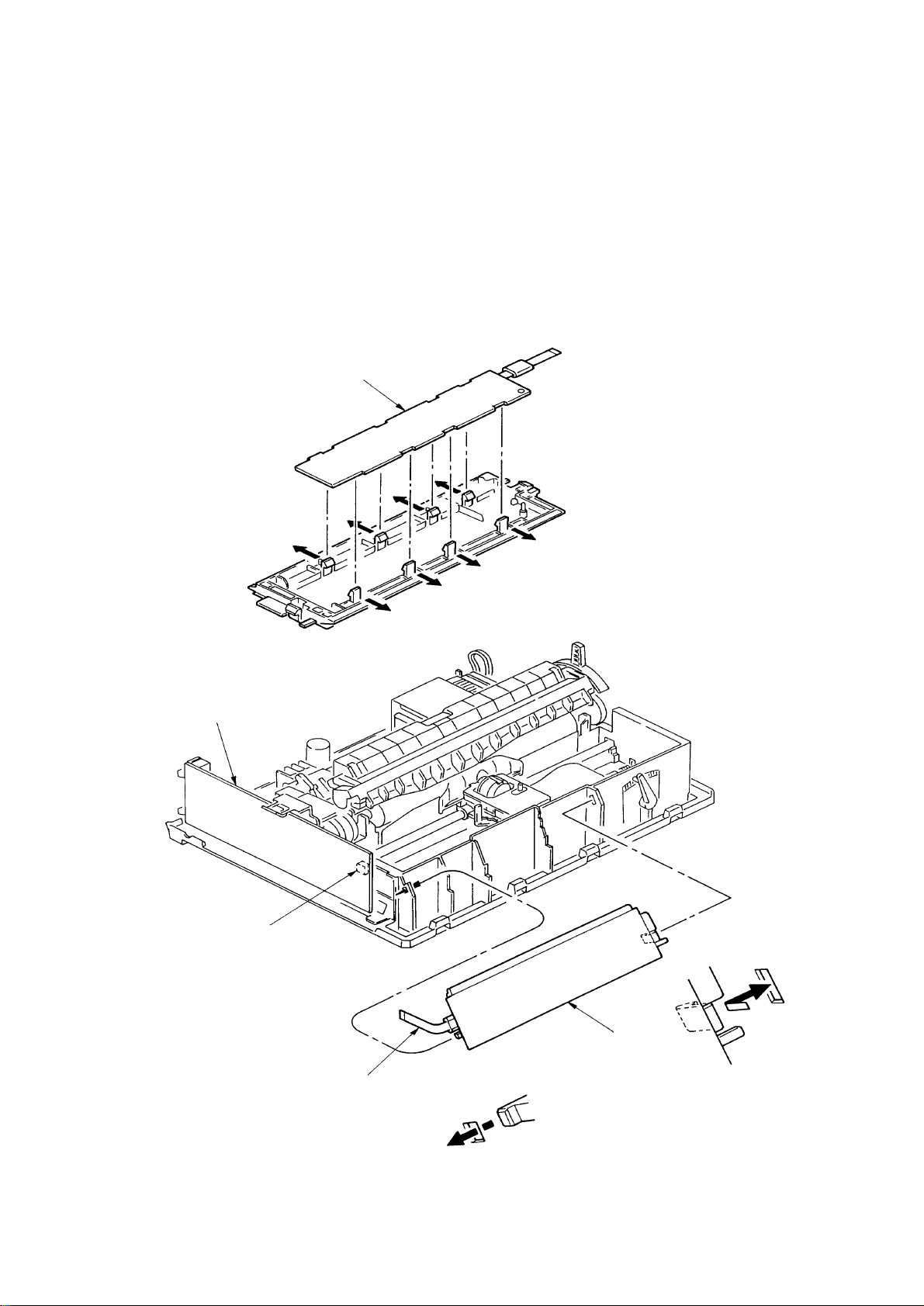
3.3.4 Upper Cover Assy, Access Cover Assy and Sheet Guide Assy
(1) Pull off the platen knob 1.
(2) Turn the change lever 2 toward the bottom position.
(3) Insert a flat-blade screwdriver into grooves (5 places) (4 places for narrow type) of frame
and twist to disengage claws of upper cover 3.
(4) Raise the front side of upper cover Assy 3 and shift toward the rear to disengage claws
(6 places) (5 places for narrow type) of frame.
(5) Raise the upper cover Assy 3 to remove.
(6) Open the access cover Assy 4 toward the front to remove.
(7) Lift up the sheet guide Assy 5 to remove.
(8) To install, follow the removal steps in the reverse order.
Remark on assembly:
Match the posts A at the both sides of the Sheet Guide 5 with the arrow marks on
the upper cover. Push the Guide into the Cover.
5
A
4
1
3
2
3 – 8
Page 65

3.3.5 Gear Case Assy
(1) Remove the printhead (see 3.31).
(2) Remove the upper cover (see 3.3.4 (1) – (5)).
(3) Move the carriage Assy to right hand side, remove two screws 1, then the space motor
2.
(4) Disconnect a carriage cable.
(5) Disengage claws (4 places).
Using a flat-blade screwdriver, push to widen the claw for easy disengagement.
(6) Remove the gear case Assy 3 in upper direction and release the carriage cable from the
cable clamp of the gear case Assy.
(7) To install, follow the removal steps in the reverse order.
Note on installation:
(1) To assemble, align the direction of the SP motor axis 4 with the Gear Hole of the Gear
Case assy.
(2) Be sure to check, and adjust if necessary, the gap between platen and printhead (see
4-1).
2
4
1
3
3 – 9
Page 66

3.3.6 PC Connector
(1) Remove the printhead (see 3.3.1).
(2) Remove the upper cover (see 3.3.4 (1) – (5)).
(3) Remove the gear case Assy (see 3.3.5).
(4) Remove the PC connector 1 from the space motor Assy 2.
(5) To install, follow the removal steps in the reverse order.
Note on installation:
(1) Do not touch the space motor 2 or terminals of PC connector 1. Also, take care to avoid
dust or foreign matters.
(2) After installation, check and adjust the gap between platen and printhead (see 4-1).
1
2
3 – 10
Page 67

3.3.7 Space Motor, Guide Roller Assy
(1) Remove the printhead (see 3.3.1).
(2) Remove the upper cover (see 3.3.4 (1) – (5)).
(3) Remove the gear case Assy (see 3.3.5).
(4) Remove the PC connector (see 3.3.6).
(5) Remove screw 2, then the guide roller Assy 3 from the space motor 1.
(6) To install, follow the removal steps in the reverse order.
Notes on installation:
(1) Do not touch the terminals of space motor 1. Also, take care to avoid dust or foreign
matters.
(2) When installing the guide roller Assy 3, push portions A and B against the space motor
1.
(3) When installing the space motor 1, align the face C with carriage frame 4 and push portion
D against the frame.
(4) After installation, check and adjust the gap between platen and printhead (see 4-1).
4
C
D
1
1
B
3
A
2
3
3 – 11
Page 68

3.3.8 Space Rack
(1) Remove the printhead (see 3.3.1).
(2) Remove the upper cover (see 3.3.4 (1) – (5)).
(3) Remove the gear case Assy (see 3.3.5).
(4) Remove the space motor (see 3.3.7).
(5) Remove the spring 1.
(6) Disengage the claw on left side of space rack 2 from the frame, and remove the space
rack 2 in upper direction.
(7) To install, follow the removal steps in the reverse order.
Note on installation:
(1) After installation, check and adjust the gap between platen and printhead (see 4-1).
1
2
1
2
2
3 – 12
Page 69

3.3.9 Carriage Cable
(1) Remove the printhead (see 3.3.1).
(2) Remove the upper cover (see 3.3.4 (1) – (5)).
(3) Remove the gear case Assy (see 3.3.5).
(4) Remove the space motor (see 3.3.7).
(5) Remove the space rack (3.3.8).
(6) Remove two screws 1, release the driver board 2 and PCB sheet 9 by lifting clamp 8,
and disconnect cable from connector 3, 4, 5, 6.
(7) Remove carriage cable 7 from fasteners on frame.
(8) To install, follow the removal steps in the reverse order.
Note on installation:
(1) Take care not to fold the carriage cable 7 during installation. Curve slightly the carriage
cable 7 when assembling into the fasteners.
(2) Make sure that the paper end lever A will not contact the Paper end Sensor 0 when
mounting the Driver Board.
9
2
6
0
8
A
7
1
2
5
1
3
4
3 – 13
Claw
7
Claw
Page 70

3.3.10 Backup Roller Holder Assy
(1) Remove the printhead (see 3.3.1),
(2) Remove the upper cover (see 3.3.4 (1) – (5)).
(3) Remove the gear case Assy (see 3.3.5).
(4) Remove the space motor (see 3.3.7).
(5) Remove the backup roller spring 2.
Disengage claws (2 places) of roller holder from the carriage frame 1, and remove the
backup roller holder assy 3.
(6) To install, follow the removal steps in the reverse order.
1
2
Note: Small round hole with metal tip on back up roller holder assy 3 should be facing
up when installing.
Claw (2 places)
3
3 – 14
Page 71

3.3.11 Platen Assy
(1) Remove the printhead (see 3.3.1).
(2) Remove the ribbon protector (see 3.3.2).
(3) Remove the pull-up roller Assy (see 3.3.3).
(4) Remove the upper cover (see 3.3.1 (1) – (5)).
(5) Turn the change lever 1 to the bottom position.
(6) Push in the lock levers 2 on both sides to unlock from the frame, then rotate them upward
by 90°.
(7) Remove the platen Assy 4 from base frame.
(8) To install, follow the removal steps in the reverse order.
2
2
2
2
4
1
3 – 15
Page 72

3.3.12 Driver Board (SDDV)
(1) Remove the upper cover (see 3.3.4 (1) – (5)).
(2) Remove two screws 1, and release the driver board 2 and PCB sheet 5 by lifting clamp
4.
(3) Disconnect all cables from driver board 2.
(4) To install, follow the removal steps in the reverse order.
Note on installation:
(1) Insert one sensor lever 3 between sensor when installing the driver board 2.
5
1
2
1
2
4
4
Sensor
2
3
3 – 16
3
Page 73

3.3.13 LF Motor
(1) Remove the printhead (see 3.3.1).
(2) Remove the ribbon protector (see 3.3.2).
(3) Remove the pull-up roller Assy (see 3.3.3).
(4) Remove the upper cover (see 3.3.4 (1) – (5)).
(5) Remove the platen Assy (see 3.3.11).
(6) Remove the driver board (see 3.3.12).
(7) Remove the left FG plate 1.
(8) Release the lock A to remove the LF motor 2.
(9) To install, follow the removal steps in the reverse order.
Remark on assembly:
(1) Press the LF Motor Cable with a portion A of the Motor Plate.
1
Lock A
2
A
3 – 17
Page 74
3.3.14 Operation Panel PCB (LEOP)
(1) Remove the upper cover (see 3.3.4 (1) – (5)).
(2) Disconnect the cable 1 from connector 3 of Driver board 2.
(3) Disengage claws on both sides from the frame, and remove the operation panel 4.
(4) Open claws (8 places) and remove the operation panel PCB 5 from the operation panel
4.
(5) To install, follow the removal steps in the reverse order.
5
2
3
4
1
3 – 18
Page 75

3.3.15 Control/Power Supply Board (SDCT)
(1) Remove the upper cover (see 3.3.4 (1) – (5)).
(2) Disconnect two flexible cable 3 from the connector 2 the Control/Power Supply Board
1.
(3) Remove the cable 5 from the connector 4 on the Control/Power Supply board 1.
(4) Remove two screws 6, and remove the Control/Power Supply Board 1.
(5) To install, follow the removal steps in the reverse order.
Remark on assembly:
(1) To mount the Control/Power Supply Board, set the change lever to the top position so
that the Switch Lever 7 will not hooked on the microswitches 8.
3
6
5
7
4
8
8
2
1
3 – 19
Page 76

3.3.16 Transformer Assy
(1) Remove the upper cover (see 3.3.4 (1) – (5)).
(2) Remove AC inlet 1 and AC switch 2 from the frame guide.
(3) Disconnect the cable 3 from the connector 4 on the Control/Power Supply Board 5.
(4) Remove a screw 6 and disconnect ground cable 7.
(5) Remove two screws 8 and shift the transformer Assy 9 to the left and remove it.
6
1
8
7
2
5
9
3
4
3 – 20
Page 77

3.3.17 Change Lever and Gears
(1) Remove the upper cover (see 3.3.4 (1) – (5)).
(2) Remove the reset spring 1, then remove the idle gear 2, the tractor gear 4 and the change
gear 5.
(3) Push back the protrusion of the Change Gear Shaft 6 with a flatblade screw driver to
remove the change lever 3.
(4) To perform mounting, follow the reverse procedure of removal.
Remark on assembly:
(1) To insert the change lever into the Change Gear Shaft 6, match the flat surface (D cut).
6
4
5
3
1
2
3
D cut
3 – 21
Page 78

3.3.18 Carriage Shaft
(1) Remove the printhead (see 3.3.1).
(2) Remove the upper cover (see 3.3.4 (1) – (5)).
(3) Remove the driver board (see 3.3.12).
Remove the FG plate (L) 2.
(4) Slide the carriage shaft 1 to the left side (in the direction of the arrow) to remove.
(5) To perform mounting, follow the reverse procedure of removal.
Note on installation:
(1) After installation, check and adjust the gap between platen and printhead (see 4-1).
1
2
3 – 22
Page 79

3.3.19 Paper Pan
(1) Remove the printhead (see 3.3.1).
(2) Remove the ribbon protector (see 3.3.2).
(3) Remove the pull-up roller assy (see 3.3.2).
(4) Remove the upper cover assy (see 3.3.4 (1) – (5)).
(5) Remove the platen assy (see 3.3.11).
(6) Release claws A .
(7) Lift up the paper chute assy 1 and remove.
(8) To perform mounting, follow the reverse procedure of removal.
1
A
3 – 23
Page 80

3.3.20 Rear Tractor Assy
(1) Remove the printhead (see 3.3.1).
(2) Remove the ribbon protector (see 3.3.2).
(3) Remove the pull-up roller assy (see 3.3.3)
(4) Remove the upper cover (see 3.3.4 (1) – (5)).
(5) Remove the reset spring (see 3.3.17 (3))
(6) Remove the tractor gear 1.
(7) Shift the drive shaft 2 to the right side to remove (in the direction of the arrow).
(8) To perform mounting, follow the reverse procedure of removal.
Remark on assembly:
(1) When the Tractor Assy (L) 3 (R) 4 have been detached from the Drive Shaft, align the
protrusions 5 of the Pin Tractor Wheels to the same direction before assembly.
5
3
4
2
1
3 – 24
Page 81

3.3.21 Rear Pressure Assy
(1) Remove the upper cover (see 3.3.4 (1) – (5)).
(2) Remove the change lever and gears (see 3.3.17).
(3) Remove the paper pan (see 3.3.19).
(4) Remove the rear pressure roller 1.
(5) Rotate the release shaft 2 and move it to the left to detach the release shaft 2.
Match the Main Frame Rib A with the protrusion B of the Release Shaft.
(6) Remove rear pressure SP assy 3.
(7) To install, follow the removal step in the reverse order.
Note: (1) At mounting release shaft 2, pay attention to the gear engagement of release
shaft 2, change arm lever 6, change gear shaft 7.
(2) There are 5 Rear pressure Spring Assemblies. Use two pieces which have
larger spring diameter on the right side. Use three remaining pieces on the
left side (for ML3321).
(3) Make sure that the Release Shaft 2 will be on top of the Support spring 4.
(4) To assemble the Release Shaft 2, make sure that the protrusion of the switch
lever 5 is in the U groove of the Release Shaft 2.
1
3
5
2
3
2
A
B
3
4
7
3 – 25
6
2
Page 82
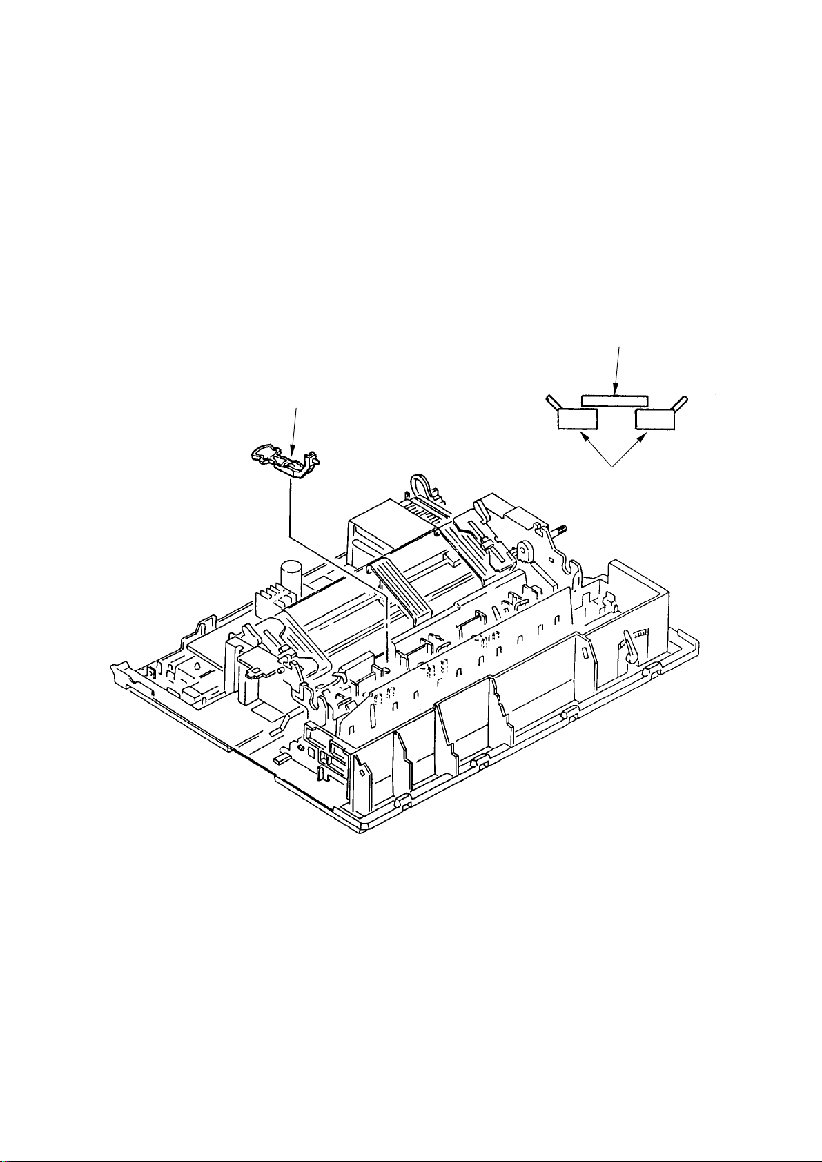
3.3.22 Switch Lever
(1) Remove the upper cover (see 3.3.4 (1) – (5)).
(2) Remove the change lever and gears (see 3.3.17).
(3) Remove the paper pan (see 3.3.19).
(4) Remove the rear pressure assy (see 3.3.21).
(5) Pull the Switch Lever toward you and remove it upward.
(6) To install, follow the removal step in the reverse order.
Remark on assembly:
(1) At the time of the Switch Lever assembly, make sure that the Micro switch on the Main
Board works properly.
Switch lever
Switch lever
Micro switch
3 – 26
Page 83

4. ADJUSTMENT
Page 84

4. ADJUSTMENT
(1) Be sure to carry out this adjustment with the printer mechanism mounted on the lower
cover.
(2) Be sure to carry out this adjustment operation on a level and highly rigid work table
(flatness: less than 0.039 inch or 1 mm) so as to minimize adjustment error.
4 – 1
Page 85

ItemNo. Specification Drawing Adjustment method
4–1–1
Gap between the platen and the print head
1) Parallelism ad-
justment
Variation of
value at the
left, the center
and the right
shall be less
than 0.02 mm
Marking
After adjustment, mark the adjust
composition with a red pen.
Left
Right
Adjust cam
It shall be measured
at 3 points: the left
end, the center and
the right end of the
platen.
Adjustment method
(1) Gap between the
platen and the
print head at the
left end and the
right end shall be
adjusted by rotating the adjust
cam.
(2) Set the adjust
lever at the
Range: 1. Press
the adjust gear
downward (in
direction A) to
push the adjust
gear and the
adjust gear out of
mesh.
2) Initial adjustment
Carriage shaft
Range: 1
Range: 5
Adjust lever
Adjust screw
0.41±0.03 mm
Left
Center
Adjust gear
Platen
Right
Print head
Adjust cam
(3) Adjust the gap by
rotating the adjust
screw in direction
B or C while the
adjust lever and
the adjust gear
are disengaged.
(4) After adjustment,
mark the adjust
cam position with
a red pen.
4 – 2
Page 86

ItemNo. Specification Drawing Adjustment method
Note 1)
The head gap shall be
Adjust lever
Adjust gear
Adjust
spring
A
B
Adjust
screw
C
measured with the
change lever set to
rear position.
Note 2)
The head gap shall be
measured positioning
the platen gear (R)
craw on the top.
Note 3)
Move the adjust
screw in clockwise
direction (in direction
B) to measure.
Adjust lever
Adjust gear
Adjust cam
Measure variation of
4–1–2 Gap=0.71
gap when range is
changed.
±0.05 at the
range 5.
Print head
Click of platen gear R
Gap
Platen
4 – 3
Page 87

ItemNo. Specification Drawing Adjustment method
Gap between the contact and the monitor
0.3mm or more
Contact
Adjust lever
Confirm followings.
Make sure that the
gap between the contact and the motor
PCB is 0.3 mm or
more.
0.3mm or
more
Motor PCB
At the time of printing
test, make sure that
the contact touches
the motor PCB and it
becomes reduced
speed mode when the
adjust lever is set to
range 2 and 4.
Touching
4 – 4
Page 88

ItemNo. Specification Drawing Adjustment method
Gap between the
4–2 1±0.5 Confirm followings.
platen and the paper
pan
1±0.5
Rear
Platen
Change lever
(At friction)
1±0.5
Bottom
Paper pan
(1) When the change
lever is set at
Friction position,
the gap between
the platen and the
paper pan at the
rear side shall be
1±0.5mm.
(2) When the change
lever is set at
Rear or Bottom
position, the gap
between the platen and the paper
pan at the front
side shall be
1±0.5 mm.
(Rear,
Bottom
position)
Change lever
4–3 Confirm followings.
Gap between the
platen and the pressure
roller
Front pressure
roller
Rear
Platen
(Center friction)
Friction
position
Rear, Bottom
position
Bottom
Paper pan
Pressure roller
(1) When the change
lever is set at
Friction position,
all the pressure
rollers shall be
pressed to the
platen.
(2) When the change
lever is set at
Rear or Bottom
position, the gap
between the platen and the pressure roller at the
rear side shall be
3mm. The front
pressure rollers
shall be pressed
to the platen.
4 – 5
Page 89

ItemNo. Specification Drawing Adjustment method
Rotation of the push
4–4–1 To confirm:
tractor
Change lever (Center friction)
Push tractor
The tractor gear shall
rotate smoothly when
the change lever is
set at Friction position.
Slight backlash
Backlash between
4–4–2 Approx. 0.05 to
gears
0.11 mm
Tractor gear
To confirm:
There shall be slight
backlash between
gears to allow smooth
rotation of gears.
(Backlash 0.05 to
0.11 mm)
4 – 6
Page 90

ItemNo. Specification Drawing Adjustment method
Ribbon feed4–5–1 To confirm:
Ribbon shall be fed
smoothly when the
carriage is moved
from side to side.
Ribbon feeding
Running load to spac-
4–5–2 To confirm:
ing mechanism
250g or less
without a ribbon cartridge
Ribbon
Load
measurement
portion
Make sure that the
power is turned off at
the time of measurement.
Ribbon
cartridge
4 – 7
Page 91

ItemNo. Specification Drawing Adjustment method
4–6 To confirm:
Engagement of the
double gear and the LF
motor idle gear of the
Platen Assy.
LF Motor
idle gear
Bias gear
Platen gear (L)
The idle gear of the
LF motor and the
platen gear (L) and
the bias gear of the
platen shall be in
mesh in such way that
the platen gear (L)
and the bias gear
rotate against each
other to pinch the
teeth of idle gear.
The idle gear stays in
mesh with the platen
gear (L) and the bias
gear and not locked.
The bias gear and the
platen gear shall be
staggered by one
teeth as shown in the
drawing.
Tension
Good
Not good
(Locked)
4 – 8
Page 92

5. CLEANING AND LUBRICATION
Page 93

5. CLEANING AND LUBRICA TION
5.1 Cleaning
[Cautions]
1. Be sure to turn OFF the AC POWER switch before cleaning. Remove the AC power cord
from the printer.
2. Avoid dust inside the printer mechanism when cleaning.
3. If a lubricated part has been cleaned, be sure to apply lubricating oil to that portion after
cleaning.
(1) Cleaning time
When the equipment operating time has reached six months or 300 hours, whichever
comes first.
(2) Cleaning tools
Dry cloth (soft cloth such as gauze), vacuum cleaner
(3) Places to be cleaned
Table 5.1 lists the places to be cleaned:
Table 5.1
Place to be cleaned Cleaning procedure
Carriage shaft and the vicinity Remove paper waste and wipe off
Paper travel surface stain, dust, ribbon waste. etc.
5 – 1
Page 94

Carriage
shaft
5 – 2
Page 95

5.2 Lubrication
This printer is designed to be maintenance free and requires no lubrication during normal
operation. However it is necessary to apply lubricant in case the printer is disassembled,
reassembled, cleaned or parts have been changed.
(1) Cleaning time
Remarks:
1) Turn off the power before cleaning.
2) Make sure that paper dust will not fall inside of the machine.
• Cleaning period:
6 months of operation or 300 hours of operation, whichever the earlier.
• Cleaning points:
Carriage shaft and surroundings: Remove paper and ribbon dust.
Paper path: Clean stains and dusts.
Paper End Sensor Remove the dust on the Sensor.
(2) Lubricant
• Pan motor oil (or equivalent): PM
• Molicort (or equivalent): EM-30L
(3) Amount of lubricant
• Medium amount A : Apply three to four drops of oil, or 0.008 inch (0.2 mm) thick grease.
• Small amount B : Apply one drop of oil (0.006±0.002 g)
(4) Areas to Avoid
No. Do not lubricate Reason Remarks
1 Platen assembly To prevent stained paper
(rubber face) and illegal paper feed.
2 Pressure roller (rubber To prevent stained paper Pay attention not to put
face) the grease on the rubber
face of the pressure roller.
3 Carriage shaft To stabilize carriage
traveling load
4 Ink ribbon To prevent blurring of print
image
5 Pin tractor To prevent stained paper
6 Flexible cable To prevent loose connection
and crack
7 Motor PCB To prevent loose connection
8 Connector terminals To prevent loose connection
5 – 3
Page 96

(5) Lubrication point
1. Ribbon feed gear Assy.
Planetary gear shaft
(upper and lower)
EM-30L-A
Idle gear shaft (upper and lower)
PM-B (0.006±0.002g)
Drive gear shaft (upper and lower)
PM-B (0.006±0.002g)
2. Space rack
Space rack
Rack upper side
Approx. 35 (greasing range)
EM-30L-A
Approx. 30 (greasing range)
5 – 4
Page 97

3. Platen Assy.
Bias gear
Contact face of platen shaft
and platen FG spring
EM-30-L-B
Grease the contact face of
platen gear (L) and bias gear
PM-B
Platen gear (L)
5 – 5
Page 98

4. Tractor driving mechanism
5
5
5
Change arm
Idle gear teeth
EM-30L-A
Reset spring
Sliding surface of
change arm and
change lever
EM-30L-A
Change lever
Tractor gear bearing portion
EM-30L-A
Gear
bearing portion
EM-30L-A
Sliding surface of
reset spring and gear
EM-30L-A
5. Tractor drive shaft
Sliding surface of FG spring and drive shaft end
EM-30L-A
Sliding surface of change
lever and gear
EM-30L-A
Drive shaft bearing portion
234
234
234
EM-30L-A
A-A Arrow view
5 – 6
Page 99

6. Pressure roller
Change arm
Support spring
Contact portion of support
spring and shaft
EM-30L-A
Contact portion of rear
holder and shaft
EM-30L-A
Sliding portion of
release shaft and rear
roller holder
EM-30L-A
Sliding portion of release
shaft and change arm
EM-30L-A
Release shaft
Front pressure roller
Controller holder
Sliding portion of rear roller holder and
release shaft cam surface (release
shaft plane portion)
EM-30L-A
Release shaft protruding
portion - 2 portions
EM-30L-A
Shaft
Rear roller holder
Bearing portion of front roller
holder and pressure roller
EM-30L-B
5 – 7
Page 100

7. Pull up roller Assy.
Pull-up roller
frame
Pull-up roller
shaft
All bearing portions
of pull-up roller
shaft and pull-up
roller frame
EM-30L-B
Gear and post
EM-30L-A
5 – 8
 Loading...