

Page 1
B6100
Page 2

User’s Guide
Every effort has been made to ensure that the information in this document is complete, accurate, and up-to-date.
The manufacturer assumes no responsibility for the results of errors beyond its control. The manufacturer also
cannot guarantee that changes in software and equipment made by other manufacturers and referred to in this
guide will not affect the applicability of the information in it. Mention of software products manufactured by other
companies does not necessarily constitute endorsement by the manufacturer.
While all reasonable efforts have been made to make this document as accurate and helpful as possible, we
make no warranty of any kind, expressed or implied, as to the accuracy or completeness of the information
contained herein.
Copyright 2002 All Rights Reserved
Oki and Microline are registered trademarks of Oki Electric Industry Company, Ltd. Energy Star is a trademark of
the United States Environmental Protection Agency.
Hewlett-Packard, HP, and LaserJet are registered trademarks of Hewlett-Packard Company.
Microsoft, MS-DOS and Windows are registered trademarks of Microsoft Corporation.
Apple, Macintosh, Mac and Mac OS are registered trademarks of Apple Computer.
Other product names and brand names are registered trademarks or trademarks of their proprietors.
As an Energy Star Program Participant, the manufacturer has determined that this product meets
the Energy Star guidelines for energy efficiency.
This product complies with the requirements of the Council Directives 89/336/EEC (EMC) and
73/23/EEC (LVD) as amended where applicable on the approximation of the laws of the member
states relating to electromagnetic compatibility and low voltage.
CAUTION
The use of original cartridges is highly recommended. Using compatible or counterfeit cartridges can
seriously damage the printer.
ii
Page 3

CONTENTS
Preface.........................................................................................................................v
Welcome ..................................................................................................................v
About the Printer ......................................................................................................v
Available Configurations......................................................................................v
Features ..............................................................................................................vi
About this Guide ......................................................................................................vii
Printer Orientation ...............................................................................................vii
Conventions ........................................................................................................vii
User’s Guide Contents ........................................................................................viii
Installation Procedure ................................................................................................1
About the Installation Procedure..............................................................................1
Safety Precautions...................................................................................................1
Handling the Printer.............................................................................................1
Step 1: Inspecting Package Contents......................................................................2
CD-ROM Contents ..............................................................................................2
Step 2: Preparing a Location for the Printer.............................................................3
Printer Weight and Dimensions...........................................................................3
Space Requirements...........................................................................................3
Environment ........................................................................................................4
Step 3: Locating Parts of the Printer ........................................................................5
Step 4: Installing the Print Cartridge ........................................................................7
General Information.............................................................................................7
Installation Procedure..........................................................................................8
Step 5: Installing Optional Printer Accessories ........................................................10
Step 6: Loading the Universal Paper Tray ...............................................................11
Step 7: Connecting the Power Cord and Turning the Printer On .............................14
Step 8: Selecting the Control Panel Language ........................................................16
Step 9: Printing a Test Page or Configuration Summary .........................................17
Test Page ............................................................................................................17
Configuration Summary.......................................................................................18
Step 10: Connecting the Printer to Host Computer..................................................19
Step 11: Installing Printer Drivers ............................................................................20
Overview .............................................................................................................20
Microsoft Windows Systems ...............................................................................20
Apple Mac OS 8x, 9x (USB) ................................................................................20
Macintosh OS X ..................................................................................................21
Step 12: Locating User Documentation ...................................................................21
Step 13: Printing a Test Document ..........................................................................21
Step 14: Using the Printer........................................................................................21
Step 15: Product Registration ..................................................................................22
Registering Your Printer ......................................................................................22
Service and Support............................................................................................22
User’s Guide
iii
Page 4

User’s Guide
Understanding and Navigating the Control Panel Menus ...................................... 23
About the Control Panel Menus............................................................................... 23
Control Panel Features............................................................................................ 23
LCD Display ........................................................................................................ 24
LED Indicators .................................................................................................... 24
Pushbuttons ........................................................................................................ 25
Navigating the Control Panel Menus ....................................................................... 26
Menu Structure ........................................................................................................ 28
Troubleshooting ......................................................................................................... 29
About Troubleshooting............................................................................................. 29
Power On Problems................................................................................................. 29
Warning Messages and Error Messages................................................................. 30
Warning Messages .............................................................................................30
Error Messages................................................................................................... 31
iv
Page 5

User’s Guide
PREFACE
WELCOME
Thank you for selecting the Oki B6100. This guide provides information and procedures to
help you set up and install your printer. Please read this guide and keep it at hand for later
reference.
This User’s Guide, along with other important user documents are contained on the CD.
ABOUT THE PRINTER
AVAILABLE CONFIGURATIONS
Oki B6100 Printer
The printer is available in the following configurations:
> Memory: 64MB
> Paper Input: One 550-sheet universal paper tray for A4/Letter/Legal, and one 100-sheet
front tray for paper, transparencies, envelopes, and other non-standard print media
> Paper Output: One 500-sheet face-down tray
> Interfaces: IEEE 1284 Parallel, USB 2.0
> Printer Languages: PCL6e, Adobe Postscript 3
Oki B6100n Printer
As above with network interface card included.
Oki B6100dn Printer
As B6100n with internal duplexing unit.
v
Page 6

User’s Guide
FEATURES
Your laser printer has the following features:
> Quality printing at a high speed
The printer has an output of 25 pages per minute with a resolution up to true 1200 dpi.
> Flexible use of paper sources and delivery methods
The base configuration of the printer includes one 550-sheet universal paper feeder and
a front tray. The paper feeder can be set to any size paper from postcard to 14 inch
legal. The front tray can be set for print media from index card size to 14 inch legal, and
also accommodates envelopes and labels. You may also add the following paperhandling options to the printer: additional 550-sheet Feeders, Envelope Feeder,
Duplexer, Offset Catch Tray.
> Easy operation
The easy-to-read control panel display clearly shows the status of printer operation.
Control panel pushbuttons allow you to access and view printer menus, submenus, and
status messages.
> Single-element toner cartridge
The integrated toner cartridge contains both the toner and the photosensitive drum in a
single housing, making replacement easy and convenient.
> Continuous printing of up to 1750 sheets
The printer can print up to 650 sheets unattended when the offset catch tray is installed,
and can print up to 1750 sheets attended when two 550-sheet feeders are installed and
used along with the front tray (100 sheets).
vi
Page 7

User’s Guide
ABOUT THIS GUIDE
PRINTER ORIENTATION
Throughout this guide, the four sides of the printer are referred to as front, rear, right, and
left. The front of the printer is the side near the control panel, and the rear of the printer is
opposite the front. The left and right sides of the printer are defined as the sides to the left
and right, respectively, of a person who is facing the front of the printer.
The CD contains the Technical Reference Manual which amplifies the description of the
product, its features and how it can be used.
CONVENTIONS
This following conventions are used throughout this guide to emphasize certain procedures
or information:
NOTE
A note is a tip or extra information that may be helpful in installing or using the printer.
CAUTION
A caution message provides information that may help you avoid equipment damage,
process failure, or inconvenience. Read all caution messages carefully.
WARNING
A warning message indicates the possibility of personal injury if a specific procedure
is not performed exactly as described in the guide. Pay close attention to these
sections and read them fully to prevent possible injury.
vii
Page 8

User’s Guide
USER’S GUIDE CONTENTS
This guide contains three sections:
Preface
The Preface describes the features of the printer and outlines the organization of this guide.
Installation Procedure
This section includes all of the steps necessary to prepare your printer for use.
Understanding and Navigating the Control Panel
This section provides a brief explanation of the control panel menus and submenus, and
illustrates how to navigate through those menus.
Troubleshooting
This section lists the error messages that may appear on the control panel display while you
are setting up and installing the printer, and also explains the possible causes of such errors
and the procedures for correcting them.
viii
Page 9
INSTALLATION PROCEDURE
ABOUT THE INSTALLATION PROCEDURE
This section guides you through the process of setting up and installing the printer. Complete
the entire installation procedure to ensure a proper installation.
SAFETY PRECAUTIONS
This printer is available in either of the following power specifications: 110V and 220V. The
specifications that apply to your printer depend on your machine configuration. To prevent
fire or shock hazards, connect the power plug only to a properly rated power outlet.
HANDLING THE PRINTER
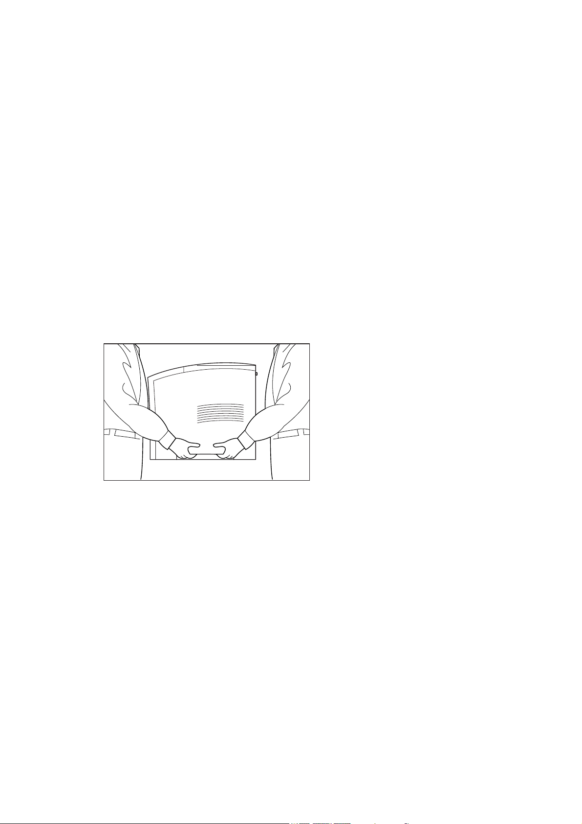
Follow the guidelines below when lifting or moving the printer:
> The printer is very heavy, and should always be lifted by two people. The weight of the
printer without paper tray, toner cartridge, and paper is about 51 lbs (23 kg). Never
attempt to lift the printer alone.
> To lift the printer, have two individuals facing each other from the front and the rear of the
printer grasp the recessed areas on each side of the printer. Do not lift the printer by
grasping any area other than these recessed areas.
> When lifting the printer, maintain proper lifting posture to prevent injuries.
Page 10
User’s Guide
STEP 1: INSPECTING PACKAGE CONTENTS
NOTE
If you have not unpacked your printer, please refer to the pictorial unpacking instructions
included in the printer packaging. If you have completed the entire procedure shown on the
unpacking instructions, you do not need to complete steps 4, 6, and 7 shown in this guide.
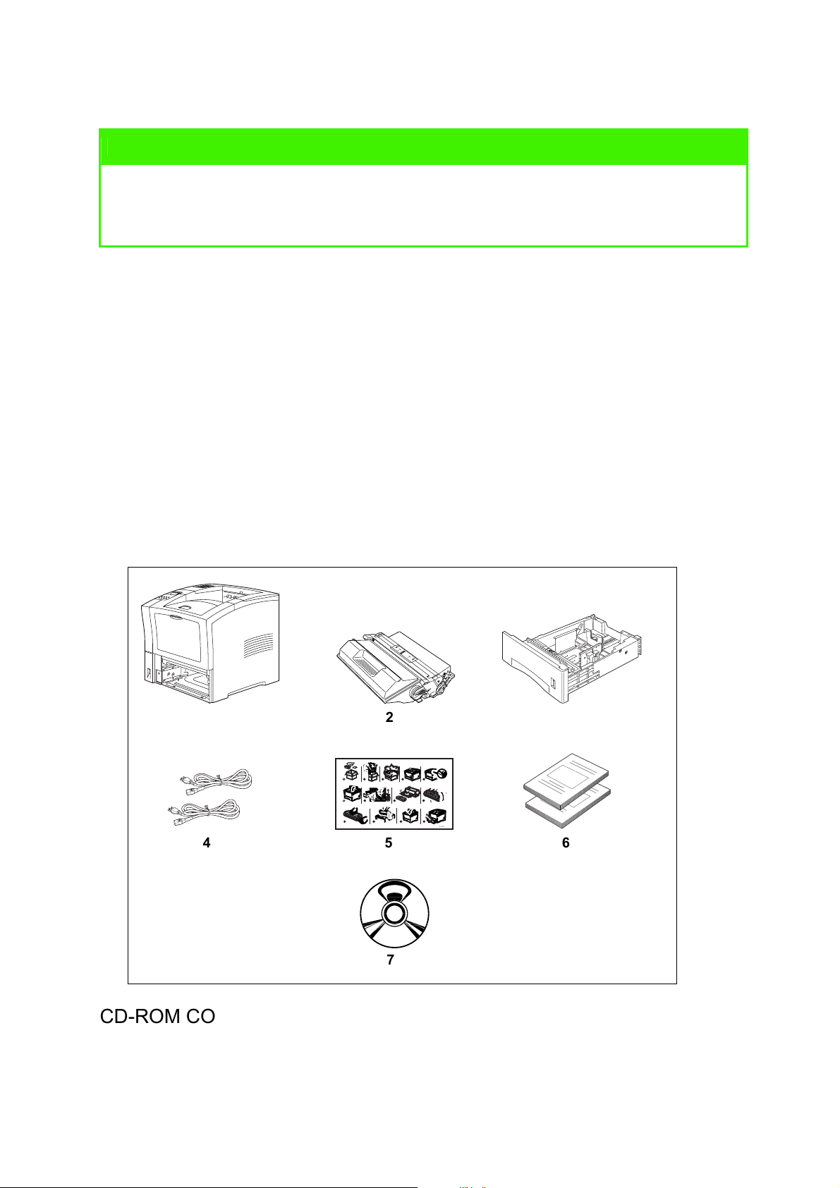
Make sure that all of the items shown below are included in the printer packaging. If any
items are missing or damaged, contact your dealer.
Figure 1: Items included in the printer packaging
1. Printer
2. Print Cartridge
3. 550-sheet Universal Paper Tray
4. Power Cord(s)
5. Unpacking Instructions and quick set-up guide
6. Safety and Warranty Booklet
7. CD-ROM
1
1
6
10
4 5 6
2
2 3 4
4
3
1
2
1
3
2
7
11
8 9
12
5
13
3
GEG-99042
7
CD-ROM CONTENTS
The Oki B6100 CD-ROM contains printer drivers, software and documentation designed to
help you fully utilise your new printer. Oki has provided an interface, under MS Windows, to
assist you in selecting the appropriate document or application.
2
Page 11
User’s Guide
STEP 2: PREPARING A LOCATION FOR THE PRINTER
PRINTER WEIGHT AND DIMENSIONS
This printer weighs approximately 51 lbs (23 kg) and should always be lifted by two people.
The dimensions of the printer are listed below.
> Printer Height: 16.3 in (413 mm)
> Printer Width (left to right): 16.6 in (422 mm)
> Printer Depth (front to back): 17.3 in (439 mm)
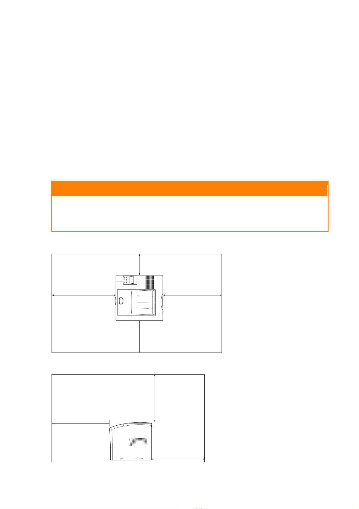
SPACE REQUIREMENTS
A certain amount of space is required for proper operation of the printer and also for
performing printer maintenance and replacing consumables. Use the following figures to plan
for appropriate clearances when determining a location for your printer.
CAUTION
There is a ventilation opening on the left side of the printer. To avoid overheating and
fire hazards, be sure to leave a clearance of at least 8 inches (200 mm) between this
opening and the nearest wall or other surface.
Figure 2: Top view of the printer.
8 inches
(200 mm)
24 inches
(600 mm)
12 inches
(300 mm)
24 inches
(600 mm)
Figure 3: Side view of the printer.
24 inches
(600 mm)
20 inches
(500 mm)
24 inches
(600 mm)
3
Page 12
User’s Guide
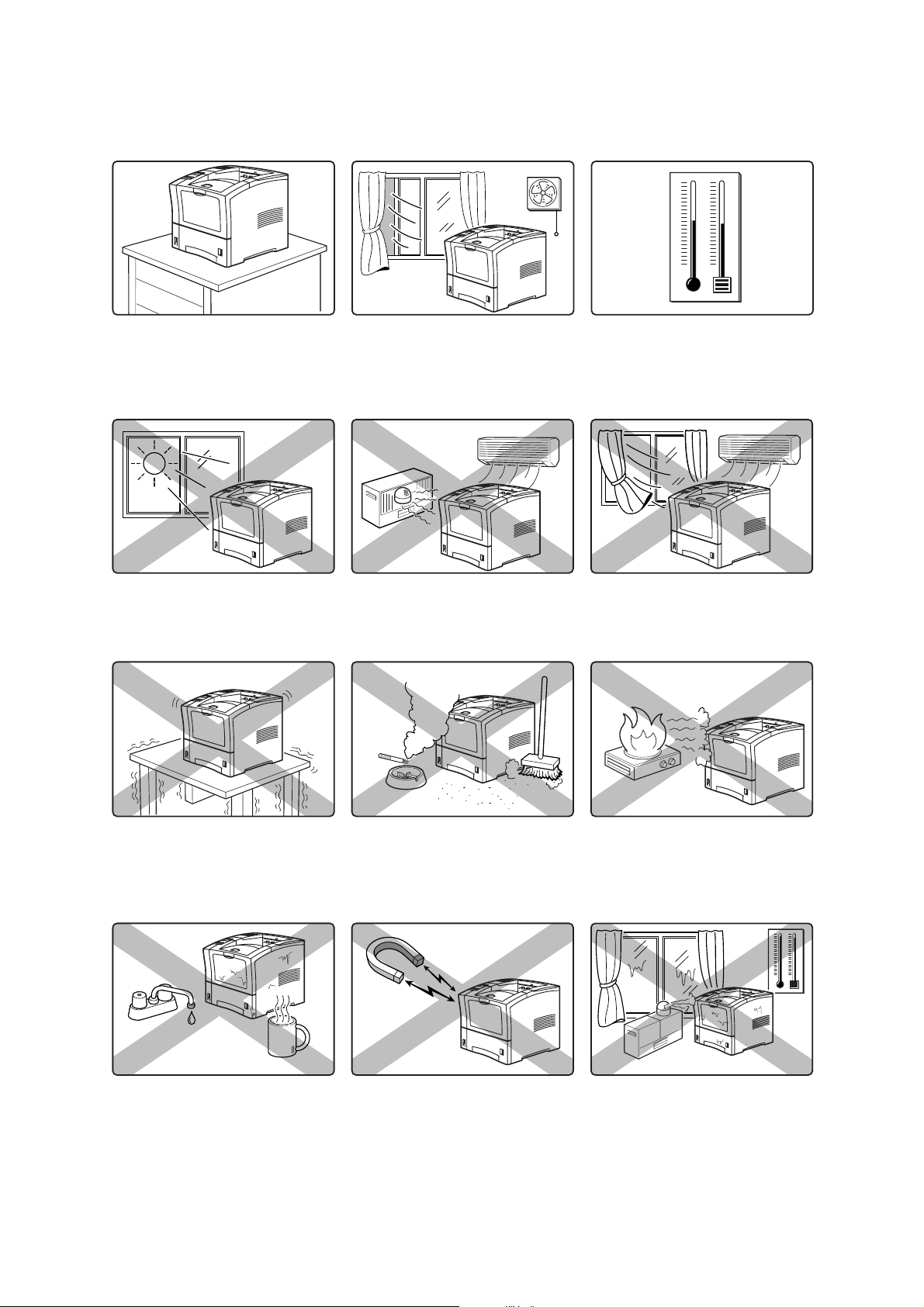
ENVIRONMENT
Use the following guidelines to determine the best location for the printer:
Horizontal, sturdy, and stable
surface
Location with good ventilation
Location with stable
temperature and humidity
Exposed to direct sunlight Near heating appliances Exposed to direct air current
Subject to vibrations Exposed to high levels of dust
Near an open flame
and contamination
Exposed to water and high
humidity
4
Exposed to magnetic fields Subject to extreme variations in
temperature and humidity.
Page 13

STEP 3: LOCATING PARTS OF THE PRINTER
The following figures indicate the names and functions of the main parts of the printer
Figure 4: Front of the Printer.
User’s Guide
1. Paper Exit Slot
2
2. Paper Output Tray
3. Control Panel
4
3
Provides access to all controls
required to operate the printer.
5
4. Front Cover
Provides access to the inside of the
6
printer, allows you to replace the toner
cartridge or remove jammed paper.
7
5. Front Tray
Provides an alternate method of
8
9
feeding paper to the printer.
Accommodates various print media, including envelopes, transparencies, and labels.
6. Tray Extension
Allows you to load large paper sizes in the front tray.
7. Power switch
1
8. 550-sheet Universal Paper Tray
Holds paper from postcard size to Legal size.
9. Paper amount indicator
Indicates the approximate remaining amount of paper.
Figure 5: Rear of the Printer.
10. Top cover
Provides access to the inside of the
printer; removing it allows you to install t
he
offset catch tray.
11. Rear cover
Provides access to the rear of the printer;
allows you to remove jammed paper or
install the duplexer.
12. Power cord connector
13. Ventilation slot
Releases hot air produced inside the
printer to prevent overheating.
11
12
10
13
5
Page 14

User’s Guide
Figure 6: Internal Parts of the Printer (Front)
14. Print Cartridge
14
Integrated cartridge contains the toner
and the photosensitive drum.
15. Front Cover
Provides access to the interior of the
printer. Allows you to replace the print
cartridge or remove jammed paper.
15
CAUTION
The fuser becomes very hot while the printer is operating. If you need to remove the
print cartridge to remove a paper jam, turn the power off and wait at least 10 minutes
before removing the print cartridge and touching the fuser.
Figure 7: Internal Parts of the Printer (Rear)
16. Fuser
16
Fixes toner onto the paper.
17. Rear Cover
Provides access to the interior of the
printer. Allows you to install the optional
duplexer or remove jammed paper.
Figure 8: Control Panel.
18. LCD Display
Shows error messages and other status
messages; also displays menus, submenus,
and settings.
19. LED Indicators
Show printer status.
20. Pushbuttons
Allow you to navigate through menus, place
a printer offline, or cancel a print job.
17
18
19
20
6
Page 15

User’s Guide
STEP 4: INSTALLING THE PRINT CARTRIDGE
GENERAL INFORMATION
The print cartridge contains the dry ink as well as the xerographic drum and associated
components that create the xerographic image on a sheet of paper. The print cartridge will
eventually run out of ink through normal use. When the toner is low, printed images will be
uneven or very light. Use the following guidelines when using or storing a print cartridge:
> An unopened and correctly stored print cartridge has a shelf life of approximately two
years.
> Do not open the box containing the print cartridge until you are ready to install the
cartridge into the printer.
> Store the print cartridge box horizontally—not on end.
> Keep the cartridge out of the reach of children. Store it in an area where the temperature
remains between 32°F and 95°F (0°C and 35°C) and the humidity remains between 15%
and 85%. If you bring a cold print cartridge into a warm room, wait a least an hour for the
temperature to stabilize before opening the cartridge box.
> Do not disassemble the print cartridge.
> Toner is a safe material. If you get any on your hands, DO NOT wash them in hot water.
Use only COLD water to wash off toner. Hot water sets the toner and makes it difficult to
remove.
> A shutter (1) protects the photosensitive drum from ambient light. Do not open the drum
shutter by hand.
1
CAUTION
Do not expose the new print cartridge to strong light for more than a few minutes
before installing it into the printer.
WARNING
Do not dispose of used print cartridges in an incinerator or in an open fire.
7
Page 16

User’s Guide
INSTALLATION PROCEDURE
Use the following procedure to replace the print cartridge:
1. Press the button on the top of the printer to open the front cover, and pull the cover all
the way open.
2. Remove the orange plastic shipping spacers from the inside of the printer.
3. Remove the new print cartridge from its packaging and remove the protective paper
sheet from the drum shutter.
4. Rock the print cartridge back and forth. Then, shake it horizontally to ensure that the
toner is evenly distributed.
8
Page 17

User’s Guide
5. On level surface, firmly hold down the print cartridge. Pull the plastic sealing tape straight
out (horizontally) from the cartridge.
6. Slide the pegs on the print cartridge into the channels on the inside of the printer, and
push the print cartridge into the printer.
7. Close the front cover. Verify that it securely locks into place
9
Page 18

User’s Guide
STEP 5: INSTALLING OPTIONAL PRINTER ACCESSORIES
The following figure shows all of the available accessories as installed on the printer.
NOTE
The printer automatically recognizes an option after the option is installed. The printer driver
does not. You must enable (activate) the option in the printer driver after the option is
installed.
The steps you will follow vary according to both your operating system and your installed
printer driver. Here are the general steps you will follow.
> Select the driver you want to work with.
> Locate the printer properties section within the printer driver.
> Use the pulldown window to select the option.
> Activate the option.
Figure 9: Optional Accessories.
1. Offset Catch Tray
Holds and separates large print jobs
by offsetting.
2. Envelope Feeder
Holds a maximum of 75 envelopes
or 100 postcards.
3. 550-Sheet Feeder
Holds a 550-sheet paper tray and
provides extra paper capacity. The
printer can accommodate two
additional 550-sheet feeders.
4. Duplexer
Enables two-sided printing.
1
2
3
4
10
Page 19

User’s Guide
STEP 6: LOADING THE UNIVERSAL PAPER TRAY
The 550-sheet universal paper tray that sits inside the printer can accommodate paper sizes
from postcard to legal. The 550-sheet universal paper tray has two width guides that are
located on the sides of the tray, and one length guide that is located near the center of the
tray. These guides allow you to adjust the size of the area that holds paper.
NOTE
The following procedure shows you how to load paper into the main paper tray. To load
paper into the optional 550 sheet paper feeder, simply complete the procedure using the
550 sheet paper tray and feeder rather than the main paper tray.
Use the following procedure to load paper into the 550 sheet universal paper tray:
1. Place the paper tray on a level surface.
2. Squeeze the locking mechanism on the rear length guide, lift it up, and slide it all the way
to the rear of the tray.
3. If the paper you are using is longer than A4 (11.7 inches/ 297 mm), press the square
green button on the bottom of the paper tray to release the rear of the tray, and pull the
tray out to extend it. This is known as the extended position.
11
Page 20

User’s Guide
4. Squeeze the right-side width guide, lift it up, and slide the guides to the sides of the tray.
5. Verify that the paper tray plate has dropped down into the base of the paper tray. If the
tray is locked in the up position, pull the lever near the front of the tray to release the
plate, or push the paper tray completely into the printer and then remove it.
CAUTION
Do not overload the tray. Verify that the paper stack is beneath the retaining clips on
both sides of the tray. Fan paper before placing it in the tray, and place paper in the
tray with the print side down, bottom edge forward.
NOTE
To avoid paper jams and other paper transportation problems, make sure the length and
width guides are adjusted to match the paper size and are locked firmly into place.
6. Align the edges of the paper and place the paper in the center of the paper tray with the
print side down. Verify that you place the paper at the center of the paper tray.
12
Page 21

User’s Guide
7. Squeeze the right width guide, lift it up, and adjust the guides to match the paper width.
8. Squeeze the length guide, lift it up, and adjust the guide to match the paper length. Verify
that the length guide is firmly seated into the gradations on the base of the paper tray.
9. Grasp the paper tray with both hands and insert it into the paper tray well on the printer.
10. Push the paper tray completely into the printer. Verify that the tray is properly seated.
13
Page 22

User’s Guide
11. Use the paper level indicator on the front right of the printer to determine when the paper
supply is low.
STEP 7: CONNECTING THE POWER CORD AND TURNING THE PRINTER ON
Use the following procedure to connect the power cord and turn the printer on.
1. Insert the power cord into the AC connector on the rear of the printer.
2. Verify that the power switch of the printer is in the [O] (off) position. Then, insert the plug
of the power cord into the AC outlet.
14
Page 23

User’s Guide
3. Turn the printer on by pressing [ I ] on the power switch on the left front of the printer.
The status message “Loading” appears on the display. This message indicates that the
printer is warming up and is not ready to print. After about 65 seconds, the status
message changes to “Ready”, indicating that the printer is ready to print.
Loading
Ready
NOTE
If an error message appears on the display after you turn the printer on, refer to the
Troubleshooting section.
15
Page 24

User’s Guide
STEP 8: SELECTING THE CONTROL PANEL LANGUAGE
English is the default language for all control panel error and status messages; however,
these messages are also available in many languages. Use the following procedure to
change the display language:
NOTE
Please see the section “Understanding and Navigating the Control Panel Menus” on
page 23 for a brief overview of the control panel and its menus and submenus.
1. Press the MENU button on the control panel.
2. Press the NEXT button until the text “System Menu” is shown on the second line of the
display.
3. Press the SELECT button to enter the system menu.
4. Press the NEXT button until the text “Display Language” is shown on the second line of
the display.
5. Press the SELECT button to enter the display language submenu. The default language
“English” is shown on the second line of the display.
6. Choose a language:
To change the control panel display language, press the NEXT button until the language
of choice is shown on the second line of the display.
7. Press the SELECT button to select the language you identified in Step 6.
8. Press the RETURN button to exit the display language submenu.
16
Page 25

User’s Guide
STEP 9: PRINTING A TEST PAGE OR CONFIGURATION SUMMARY
TEST PAGE
Printing a test page verifies that the printer is operating correctly. Use the following
procedure to print a test page.
1. Press the MENU button on the control panel.
2. Press the NEXT button until the text “Functions” is shown on the second line of the
display.
3. Press the SELECT button to enter the functions submenu.
4. Press the NEXT button until the text “Print Test” is shown on the second line of the
display.
5. Press the SELECT button to enter the print test submenu.
6. Press the NEXT button to toggle between “Single” and “Continuous”. If you choose
Single, the printer will print a single test page. If you choose “Continuous”, the printer
will continue printing pages until you press the START/STOP button.
7. Press the SELECT button to print the test page(s).
Figure 10: Test Page.
17
Page 26

User’s Guide
CONFIGURATION SUMMARY
A configuration summary lists the current printer settings. Use the following procedure to
print a configuration summary.
1. Press the MENU button on the control panel.
2. Press the NEXT button until the text “Functions” is shown on the second line of the
display.
3. Press the SELECT button to enter the functions submenu.
4. Press the NEXT button until the text “Print Summary” is shown on the second line of the
display.
5. Press the SELECT button to print the configuration summary page(s).
NOTE
The content of the configuration summary for your printer is dependent upon the optional
printer accessories that are installed. The summary shown below is for a printer with several
optional printer accessories installed—your configuration summary may not contain all of
the information included below.
Figure 11: Configuration Summary.
18
Page 27

User’s Guide
STEP 10: CONNECTING THE PRINTER TO HOST COMPUTER
You must connect the printer to your computer using an IEEE 1284 parallel cable or a USB
cable. These cables are user-supplied. The printer does not include either of these cables.
The default configuration of your printer has the USB port turned off.
If you would like to use the USB port instead of the parallel port, use the following procedure
to turn the USB port on.
1. Press the MENU button on the control panel.
2. Press the NEXT button until the text “Interface Menu” is shown on the second line of the
display.
3. Press the SELECT button to enter the interface menu.
4. Press the NEXT button until the text “Port” is shown on the second line of the display.
5. Press the SELECT button to enter the port submenu.
6. Press the NEXT button until the text “USB” is shown on the second line of the display.
7. Press the SELECT button to enter the USB submenu.
8. Press the NEXT button until the text “On” is shown on the second line of the display.
9. Press the SELECT button to change the USB setting to “On”.
10. Press the START/STOP button to exit the menu system.
NOTE
For more information about USB settings, please refer to the Technical Reference Guide
included on the CD-ROM.
19
Page 28

User’s Guide
STEP 11: INSTALLING PRINTER DRIVERS
OVERVIEW
The installation procedure(s) you will use for your printer vary according to:
> Operating System
> Usage of the USB port
> Network connection
MICROSOFT WINDOWS SYSTEMS
1. With Windows running, insert the B6100 CD-ROM into your CD-ROM drive.
2. If the CD does not run automatically, use Start – Run… and enter E:\setup (where E is
your CD-ROM drive) in the Open field.
3. Click on OK.
4. The setup program will give you a number of options, such as changing the printer
operator panel language and making a test print to ensure that your printer is operating
correctly.
5. Click on Driver Installation then Install Printer Driver and follow the on-screen prompts
to complete your printer driver installation.
APPLE MAC OS 8X, 9X (USB)
1. Power on the printer and the host computer (please refer to STEP 10, on previous page).
2. Ensure that the “Apple LaserWriter Software” is installed.
3. Attach the USB cable to the host and the printer. Note that the printer is considered a
“self powered” device and as such may be plugged into any available USB port on the
Macintosh, including the one on the keyboard .
4. Open the Desktop Printer Utility (installed when you installed the Apple Laser Writer
Software).
5. Choose the correct driver to use, depending on the printer you are installing.
6. Choose Printer (USB) and press OK.
7. Choose the PPD file that corresponds to your printer.
8. Choose the correct printer.
9. Press Create.
10. You now have a desktop shortcut to the USB printer and are ready to print.
20
Page 29

User’s Guide
MACINTOSH OS X
The installer program is a "unified" installer. This means that the same program runs on both
Mac OS X and Mac OS 9.x and earlier. It should work intelligently, and display only the
appropriate options for your operating system.
1. Place the software CD-ROM in the CD-ROM drive.
2. Double click the CD icon
3. Double click Language folder.
4. Double-click the Install Oki Software shortcut icon.
This launches the installer program. Follow the on-screen instructions. Default state installs
all drivers, deselect those not required.
If you wish to find out more about the software that is included, please refer to the Help
facility
STEP 12: LOCATING USER DOCUMENTATION
To locate other documentation that will assist you in operating and maintaining your printer,
go to the EUM folder on the CD-ROM. You can open and read these guides directly from the
CD-ROM, save the guides to the hard drive of your computer, or print the guides. The
GUIDES folder includes the following documents in Adobe PDF format:
> User’s Guide (in a range of languages)
> Technical Reference Guide (English)
> Other documents for printer options
Refer to the INDEX.TXT file included in the GUIDES folder for more information about the
documentation.
STEP 13: PRINTING A TEST DOCUMENT
After completing the installation procedure, verify that the printer is working correctly by
printing a document from an application. If the printer is not functioning correctly or if an error
message is displayed on the control panel, see the “Troubleshooting” section on page 29.
STEP 14: USING THE PRINTER
Once you have completed the installation procedures, if you require further information,
please refer to the Technical Reference Guide included on the CD-ROM.
21
Page 30

User’s Guide
STEP 15: PRODUCT REGISTRATION
Register your printer by visiting www.okieurope.com and selecting your local language.
www.okieurope.com is a powerful area of our web site designed to help you get the most
from your OKI printer. It represents our commitment to providing you with the latest updates
about your OKI product, and getting the details on OKI programs and services.
REGISTERING YOUR PRINTER
You can register your printer by:
> visiting our website at http://www.okieurope.com and selecting your local language.
Click on Product Registration.
> using the OKI Menu Installer.
Click on Register Your Printer.
SERVICE AND SUPPORT
If you need further assistance or have questions
> See our web site:
http://www.okieurope.com
> Contact your local supplier.
22
Page 31

User’s Guide
UNDERSTANDING AND NAVIGATING THE CONTROL PANEL MENUS
ABOUT THE CONTROL PANEL MENUS
This section explains the control panel and its functions, and also demonstrates how to
navigate throughout the various menus and submenus that allow you to view and change the
printer settings.
NOTE
Settings in your software application will override any settings in your printer driver. Your
printer driver settings will override any settings from the printer menu or printer front panel.
CONTROL PANEL FEATURES
The control panel is located on the front of the printer. It contains the display, indicators, and
pushbuttons that allow you to view and change the printer settings.
The figure below shows the control panel features.
Figure 12: Control Panel.
1. LCD Display
2. LED Indicators
3. Push Buttons
1
2
3
23
Page 32

User’s Guide
LCD DISPLAY
The LCD display shows status and error messages that inform you of the current status of
the printer, and also displays menus, submenus, and printer settings when you are in the
menu system. The display contains two lines of text, each with a maximum of sixteen
characters.
LED INDICATORS
The LED indicators also indicate printer status. The four indicators can each be on, off, or
blinking, indicating different phases of printer operation. The table below explains the LED
indicators.
LED Color When Off When On When Blinking
Green Printer is NOT
Green Printer is IDLE Printer is ACTIVE
Green POWER is off POWER is on Power Saver Mode ON
Yellow Printer is not in
READY
error mode
Printer is READY not applicable
Printer is WAITING (a partial
(processing a job)
There is an error that
requires user intervention,
such as a paper jam, a
service call required, etc.
job has been printed, and the
printer is waiting for additional
job data)
not applicable
24
Page 33

User’s Guide
PUSHBUTTONS
The control panel pushbuttons allow you to access and navigate menus, and also assist you
in recovering from printer errors. The table below explains the functions of the eight
pushbuttons.
Pushbutton Function
START/STOP—Push this button to start or stop the printer, or to exit the menu
system.
MENU—Push this button to enter the menu system.
NEXT—Push this button to move to the next menu, submenu, or setting within the
same level of the menu structure.
PREVIOUS—Push this button to return to the previous menu, submenu, or option
within the same level of the menu structure.
SELECT—Push this button to select the menu or submenu that is shown on the
second line of the display or to choose and save the setting shown on the second line
of the display.
CANCEL—Push this button to cancel an action.
STATUS—Push this button to enter the Status Menu and view the current status of
printer.
RETURN—Push this button to move up one level in the menu structure to the menu
shown on the first line of the display.
25
Page 34

User’s Guide
NAVIGATING THE CONTROL PANEL MENUS
NOTE
Settings in your software application will override any settings in your printer driver. Your
printer driver settings will override any settings from the printer menu or printer front panel.
When you press the MENU button on the control panel, you enter the printer’s menu system.
At that point, the first line of the display contains the text “Menu”, indicating that you are in
the menu system. The second line of the display lists the active menu, which you can change
by pressing the NEXT or PREVIOUS button.
Menu
Paper Menu
If you press the NEXT button repeatedly, the second line of the display cycles through the
main menus in the following order:
> Paper Menu
> Interface Menu
> PS Menu
> PCL Menu
> System Menu
> Quality Menu
> Functions
NOTE
Additional menus and submenus may appear in the printer menu system when other
options are installed.
The following figure shows the sequence of pushbuttons and display messages that would
allow you to change the number of copies printed. This example illustrates the basic
relationship between menus and submenus and demonstrates how the NEXT, PREVIOUS,
SELECT, and RETURN buttons help you to navigate through the menus.
26
Page 35

Figure 13: Navigating the Paper Menu.
User’s Guide
Menu
Paper Menu
Copies
2
Copies
3
Menu
Interface Menu
Copies
1
Paper Menu
Copies
1. Press the MENU button on the control panel.
Menu
Paper Menu
Paper Menu
Copies
Menu
Paper Menu
2. Press the NEXT button until the text “Paper Menu” is shown on the second line of the
display.
3. Press the SELECT button to enter the paper menu.
4. Press the NEXT button until the text “Copies” is shown on the second line of the display.
5. Press the SELECT button to enter the copies submenu.
6. Press the NEXT or PREVIOUS button to increase or decrease the number of copies
printed.
7. Press the SELECT button to save this setting.
8. Press the START/STOP button to exit the menu system.
NOTE
Settings in your software application will override any settings in your printer driver. Your
printer driver settings will override any settings from the printer menu or printer front panel.
27
Page 36

User’s Guide
MENU STRUCTURE
Settings in your software application will override any settings in your printer driver. Your
printer driver settings will override any settings from the printer menu or printer front panel.
The following figure shows the structure of the control panel main menus and submenus. For
more specific information about using and navigating the printer menu system, see the
Technical Reference Guide provided on the CD-ROM.
Figure 14: Printer Menu Structure.
Paper Menu
Copies
Default Source
Manual Feed
Output Tray
Media Size/Type
Front
Tray 1
Tray 2 (optional)
Tray 3 (optional)
Blank Pages
Tray Linking
System Menu
Factory Defaults
Display Language
Powersaver
Wait Timeout
Job Timeout
Jam Recovery
Hex Print
Reset Toner Life
Interface Menu
Port
Parallel
Network Card 1
USB
Parallel Setup
Interpreter
Format
Mode
Delay Out Close
USB Setup
Interpreter
Format
Delay Out Close
Quality Menu
Resolution
Toner Saver
Print Density
PS Menu
Print PS Errors
Manual Feed TO
Functions
Reset Printer
Print Summary
Print Test
Print Fonts
PCL Menu
Orientation
Font Source
Font Number
Pitch
Symbol Set
Macro Filter
Lines Per Page
CR Mode
LF Mode
FF Mode
Parameter Values
Print Area
NOTE
Additional menus and submenus may appear in the printer menu system when other
options are installed.
28
Page 37

User’s Guide
TROUBLESHOOTING
ABOUT TROUBLESHOOTING
This section provides procedures to identify and solve problems that may occur while you are
setting up and installing the printer.
POWER ON PROBLEMS
If you have problems turning on the printer, check the possible causes listed in the table
below. If the printer will not start after checking these items, turn the printer off, disconnect
the power cord from the AC outlet, and contact your dealer or an authorized service provider.
Description Possible Cause Action
There is no power.
The power switch is not set to
[ I ] (on).
The power cord is not properly
plugged into an AC outlet or into
the AC connector on the rear of
the printer.
Voltage of the AC power is not
correct.
The fuse on the power cord is
not functioning. (UK only)
The AC wall outlet is not
functioning.
There is interference from other
electrical devices on the same
circuit.
Check the power switch.
Set the power switch to [ O ] (off).
Then, connect the power cord firmly to
the AC connector and to the AC outlet.
Verify that the AC outlet is rated for the
voltage of your printer.
Verify that the fuse on the power cord
is intact. (UK only)
Verify that voltage is present at the AC
wall outlet by connecting another
electrical device to the outlet. If power
does not flow to the other device,
check the AC wall outlet circuit
breakers for a tripped breaker.
Unplug all electrical devices from the
AC wall outlet circuit, and then
reconnect only the printer. Turn printer
power on.
Power is frequently
interrupted.
Thermal sensors may have shut
down the printer.
The printer is malfunctioning. Turn the printer off. Disconnect the
Turn the printer off. Wait 20 minutes.
Then, turn the printer back on.
power cord from the AC outlet. Contact
your dealer or an authorized service
provider.
29
Page 38

User’s Guide
WARNING MESSAGES AND ERROR MESSAGES
The control panel display shows both warning message and error messages.
Warning messages use only the second line of the display and indicate conditions that do not
prevent the printer from operating. For example, if Tray 1 is out of paper but the printer is
currently drawing paper from Tray 2, a warning message will appear on the second line of
the display indicating that Tray 1 is out of paper—but the printer will continue to operate,
drawing paper from Tray 2.
Error messages use both lines of the display and indicate conditions that prevent the printer
from operating. The first line of an error message contains the error code and type of error,
while the second line of the display contains information about the action required to recover
from the error.
When the control panel displays a warning or error message, refer to the following tables and
complete the actions recommended for the specific message that is shown.
WARNING MESSAGES
The following table lists warning messages, possible causes, and the actions required to
correct each cause.
Warning Message
Line 2 of display
Paper Out Tray 1 There is no paper in Tray 1. Add paper to the tray.
Paper Out Tray 2 There is no paper in Tray 2. Add paper to the tray.
Paper Out Tray 3 There is no paper in Tray 3. Add paper to the tray.
Output Tray Full The output tray is full. Remove paper from the tray.
Offset Tray Full The offset output tray is full. Remove paper from the tray.
Toner Low The toner is low. Replace the print cartridge soon.
Maintenance Req Maintenance is required. Contact an authorised service provider.
Possible Cause Action
30
Page 39

User’s Guide
ERROR MESSAGES
The table below lists error messages, the possible causes of each error, and the actions
required to recover from each error.
Error Message
Line 1
E2 JAM MISFEED
E3 FUSER JAM
E4 EXIT JAM
E6 JAM OFF. TRAY
E7 JAM DUPLEX
E5 COVER OPEN
E5 COVER OPEN
J3 TONER CART.
TRAY 1 MISSING
TRAY 2 MISSING
TRAY 3 MISSING
Error Message
Line 2
Remove Paper There is a paper jam
Close Top Cover The top cover is open. Close the top or rear cover.
Close Rear Cover The rear cover is open. Close the offset tray cover.
Install/Reset The print cartridge is not
Insert Tray Tray 1 is not in the
Insert Tray Tray 2 is not in the
Insert Tray Tray 3 is not in the
Possible Cause Action
Remove the jammed paper
inside the printer.
installed, or an incorrect
cartridge is installed.
printer.
optional feeder.
optional feeder.
from the indicated location.
See the online Technical
Reference Guide (on the
CD-ROM) for information
about removing paper jams.
Install the correct print
cartridge according to the
specifications.
Insert the tray.
Insert the tray.
Insert the tray.
LOAD PAPER
TRAY1
LOAD PAPER
TRAY2
LOAD PAPER
TRAY3
LOAD PAPER
FRONT
PAPER SIZE
ERROR
OUTPUT TRAY
FULL
OFFSET TRAY
FULL
Paper Size/
Media Type
Paper Size/
Media Type
Paper Size/
Media Type
Paper Size/
Media Type
Paper Size/
Press Start
Remove Paper The output tray is full. Remove paper from the tray.
Remove Paper The offset output tray is
Tray 1 is empty. Load paper into the tray.
Tray 2 is empty. Load paper into the tray.
Tray 3 is empty. Load paper into the tray.
The front tray is empty. Load paper into the tray.
The paper size is not
supported by the printer.
full.
Check paper size
specifications and load paper
that meets specifications.
Remove paper from the tray.
31
Page 40

User’s Guide
Error Message
Line 1
U2 ROS FAILURE
U4 FUSER
FAILURE
ENV UNIT FAILURE
OFFSET TRAY FAIL
OPTION TRAY FAIL
DUPLEX FAILURE
MAIN MOTOR FAIL
ENGINE NV FAIL
FAN FAILURE
MAINTENANCE
REQ
Error Message
Line 2
Call Service The ROS has failed.
Call Service The fuser has failed.
Check Feeder The envelope unit was
Call Service The offset tray was
Call Service One of the optional trays
Call Service The duplexer was
Call Service The main motor has
Call Service The engine has failed.
Call Service The fan has failed.
Press Start The printer needs
Possible Cause Action
removed or has failed.
removed or has failed.
has failed.
removed or has failed.
failed.
maintenance.
Turn the printer off, then turn
it on. If the problem recurs,
contact an authorised service
provider.
Press the START button.
32
 Loading...