

Page 1

B410/B420/B430/MPS420b
Maintenance Manual
080409B
Oki Data CONFIDENTIAL
Page 2

Copyright © 2008 by Oki Data. All Rights Reserved
Oki Data America's, Inc. ("Oki Data"), authorizes you to view, copy, and print
documents published by Oki Data for noncommercial use within your organization only.
In consideration of this authorization, you agree and acknowledge that any copy of these
documents shall retain all copyright and proprietary rights contained herein. Each
document published by Oki Data may contain additional copyright information and
proprietary notification relating to that individual document.
Nothing contained herein shall be construed as conferring by estoppel, implication or
otherwise any license or right under any patent or trademark of Oki Data, Oki Electric
Industry Co., Ltd. ("Oki Electric"), or any third party. Except as provided above nothing
contained herein shall be construed as conferring any license or right under any Oki
Data copyright.
Oki Data has taken care to insure that the information which follows is complete,
accurate and up-to-date. However, Oki Data assumes no responsibility for errors or
omissions which may occur. All the information provided is subj ect to change from time
to time at the sole discretion of Oki Data.
All publications may include technical inaccuracies or typographical errors. We reserve
the right to make periodic changes, additions, and deletions to publications without
notice.
The most up-to-date drivers and manuals are available from the web site:
http://www.okiprintingsolutions.com
Page 3
Oki Data CONFIDENTIAL
This Maintenance Manual describes the maintenance methods in the printer field for the maintenance
personnel. In addition, regarding the handling and operating method of the printer, please refer to the "User’
s Manual".
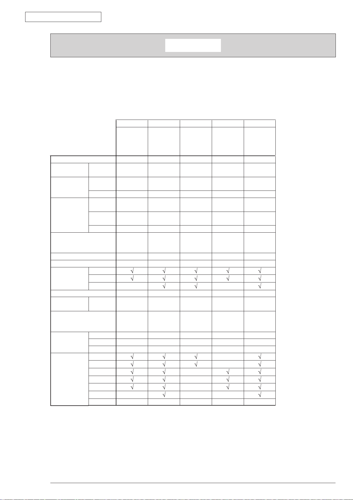
The differences between various types of printers described in this Maintenance Manual are as follows.
PREFACE
PREFACE
B410d B410dn B420dn B430d B430dn
Engine speed (letter/A4)
Resolution
Emulation
Max.
resolution
Standard
Option
LCD
Operation
panel
display
Switch
LED lights
Input tray (Manual/Auto)
Input tray (1st bin)
Maximum Input capacity
USB 2.0
Interface
Parallel
Ethernet
Auto Duplex
Monthly Duty
Cycle
Maximum
Toner life@ISO19752
Dimensions
(inch./mm)
Width
Depth
Height
ODA 100v
ODA 200v
Sales
Territories
OEL
AOS 1byte
AOS 2byte
Japan
China
30/28 30/28 30/28 30/28 30/28
2400 x 600
dpi
PCL6/SIDM PCL6/SIDM PCL6/SIDM
N/A N/A N/A N/A N/A N/A
16 character x 2 16 character x 2 16 character x 2 16 character x 2 16 character x 2 16 character x
1 (online/
offline)
2 2 2 2 2 2
Single sheet
manual feed
250 sheets 250 sheets 530 sheets 250 sheets 250 sheets 530 sheets
781 781 1110 830 830 1110
N/A N/A
Standard Standard Standard Standard Standard Standard
50,000 pages 50,000 pages 70,000 pages 70,000 pages 70,000 pages 70,000 pages
3,500
14.5”/369mm 14.5”/369mm 14.5”/369mm 14.5”/369mm 14.5”/369mm
15.6"/395mm 15.6"/395mm 15.6"/395mm 15.6"/395mm 15.6"/395mm
10.6"/268mm 10.6"/268mm 11.7"/297mm 10.6"/268mm 10.6"/268mm
N/A N/A N/A
TBD TBD TBD TBD TBD
2400 x 600
dpi
1 (online/
offline)
Single sheet
manual feed
3,500 (7,000
available for
JPN only)
2400 x 600
dpi
6 6 6 6
50 sheets
Multi Purpose
Feeder
3,500/7,000/
10,000
N/A
N/A
N/A
1200 x 1200
dpi
PCL6/PS3/
SIDM
50 sheets
Multi Purpose
Feeder
3,500/7,000 3,500/7,000
N/
N/A
1200 x 1200
dpi
PCL6/PS3/
SIDM
50 sheets
Multi Purpose
Feeder
dp
PCL6/PS3/
SIDM
2
50 sheets
Multi Purpose
Feeder
3,500/7,000/
10,000
Note!
• It is prohibited to reprint entire or partial of the content without prior consent.
• For the reason of printer improving and manual content revising, the content of this
maintenance manual may change without any warning in the future.
43984801TH Rev.1
/
Page 4

Oki Data CONFIDENTIAL
1. CONFIGURATION ........................................................................................................7
1.1 System Configuration ............................................................................................................................7
1.2 Printer Configuration ..............................................................................................................................8
1.3 Optional Configuration ..........................................................................................................................11
1.4 Specification .........................................................................................................................................12
1.5 Printing display .....................................................................................................................................15
1.5.1 VCCI label, Serial No. label ............................................................................................................15
1.5.2 Warning label ..................................................................................................................................15
1.5.3 Warning / Caution display ...............................................................................................................16
2. Operational explanation .............................................................................................17
2.1 Electrophotographic process mechanism ............................................................................................17
2.2 Printing process ....................................................................................................................................24
2.3 Toner entrance detection ......................................................................................................................28
Contents
Contents
3. Parts replacement ......................................................................................................30
3.1 Preparation for parts replacement ........................................................................................................30
3.2 Parts layout ...........................................................................................................................................32
3.3 Parts replacement method ...................................................................................................................37
3.3.1 LED Head .......................................................................................................................................38
3.3.2 Roller-Transfer ................................................................................................................................39
3.3.3 Cover-Side-R ..................................................................................................................................40
3.3.4 Cover-Side-L ..................................................................................................................................41
3.3.5 CU Board ........................................................................................................................................42
3.3.6 Motor-DC-Main ..............................................................................................................................43
3.3.7 OPE Cover-Assy ............................................................................................................................44
3.3.8 Ope-Board ......................................................................................................................................45
3.3.9 MPT-Assy (In case of B410dn, it is Manual-Assy) ..........................................................................46
3.3.10 Front-Guide-Assy .........................................................................................................................47
3.3.11 Roller-Assy-Feed ..........................................................................................................................48
3.3.12 Guide-Paper-Duplex .....................................................................................................................49
3.3.13 Stacker-Cover-Assy ......................................................................................................................50
3.3.14 Fuser-Assy ...................................................................................................................................51
3.3.15 Rear-Cover-Assy ..........................................................................................................................53
3.3.16 Frame-Assy-Lower .......................................................................................................................54
3.3.17 High voltage / Low voltage power board .......................................................................................56
3.3.18 Plate-Bracket-Motor ......................................................................................................................57
3.3.19 Roller-Back up ..............................................................................................................................58
3.3.20 Roller-Resist .................................................................................................................................59
3.3.21 Lever-In-Sensor ............................................................................................................................60
3.2.22 Lever-Eject-Sensor/Photo-Interrupter ...........................................................................................61
3.3.23 Lever-End/Lever-Duplex/Lever-Cassette/Gear-Assy-Clatch ........................................................62
3.3.24 Paper feeding roller (Roller-Pick-Up,Roller-Feed-NOW,Roller-Assy-MPT) ..................................64
43984801TH Rev.1
/
Page 5

Oki Data CONFIDENTIAL
4. ADJUSTMENT ...........................................................................................................66
4.1 Category and function of maintenance mode .......................................................................................66
4.4.1 User maintenance mode (Administrator Menu) .............................................................................66
4.1.2 System maintenance mode (System maintenance menu) .............................................................71
4.1.3 Engine maintenance mode .............................................................................................................76
4.1.4 Environment mode setting ..............................................................................................................84
4.1.5 EEPROM Initialization ....................................................................................................................85
4.2 Adjustment at part replacement ...........................................................................................................86
4.2.1 EEPROM data upload / download method .....................................................................................86
5. Periodic Maintenance .................................................................................................87
5.1 Periodic Replacement Parts .................................................................................................................87
5.2 Cleaning ...............................................................................................................................................87
5.2.1 Cleaning of LED lens array .............................................................................................................87
5.2.2 Cleaning Page Function .................................................................................................................89
6. Procedures for Repairing ...........................................................................................90
6.1 Troubleshooting ....................................................................................................................................90
6.2 Points to be checked before modifying printing problems. ....................................................................90
6.3 Points to be checked when the printing problems are modified ...........................................................90
6.4 Preparation for Troubleshooting ............................................................................................................90
6.5 Troubleshooting Flow ............................................................................................................................91
6.5.1 LCD Status Message/ Trouble Table ...............................................................................................91
6.5.2 LCD Message Troubleshooting.....................................................................................................103
6.5.3 Print Troubleshooting ....................................................................................................................111
Contents
7. Connection Diagram .................................................................................................119
7.1 Connection diagram ...........................................................................................................................119
7.2 Board Layout ......................................................................................................................................120
7.3 Resistance value ................................................................................................................................134
Appendix A Centronics Parallel Interface .....................................................................136
Appendix B USB Interface ...........................................................................................143
Appendix C Maintenance Manual for Second Tray unit ................................................145
1 Overview................................................................................................................................................145
1.1 Function ...........................................................................................................................................145
1.2 Exterior and Parts Name .................................................................................................................145
2. Description for Operation of Second Tray unit ......................................................................................146
3. Part Replacement .................................................................................................................................147
3.1 Precautions on replacing parts ........................................................................................................147
3.2 Arrangement of Parts ......................................................................................................................148
3.3 How to Replace Parts ......................................................................................................................149
3.3.1 Roller-Pick-Up, Roller-Feed-Now .............................................................................................150
3.3.2 Guard-Connector. Connector (9715S-08Z02-G4C) ..................................................................151
3.3.3 Roller-Feed ...............................................................................................................................152
3.3.4 Board-OT7 ................................................................................................................................153
43984801TH Rev.1
/
Page 6

Oki Data CONFIDENTIAL
3.3.5 CONN Cord-AMP8P-AMP8P ...................................................................................................154
3.3.6 Gear-Assy-Clatch .....................................................................................................................155
3.3.7 Frame-Assy-Retard, Spring-Retard ..........................................................................................157
4. Cleaning of Paper Feed Roller and Separation Roller ..........................................................................158
5. Procedure for Troubleshooting ..............................................................................................................159
5.1 Precautions for Troubleshooting ......................................................................................................159
5.2 Preparation before Troubleshooting .................................................................................................159
5.3 Troubleshooting Method ..................................................................................................................160
5.3.1 LCD Status Message List .........................................................................................................161
6. Connection Diagram .............................................................................................................................163
6.1 Connection diagram ........................................................................................................................163
6.2 Board Arrangement .........................................................................................................................163
Appendix D Network Interface .....................................................................................165
Contents
43984801TH Rev.1
/
Page 7
Oki Data CONFIDENTIAL
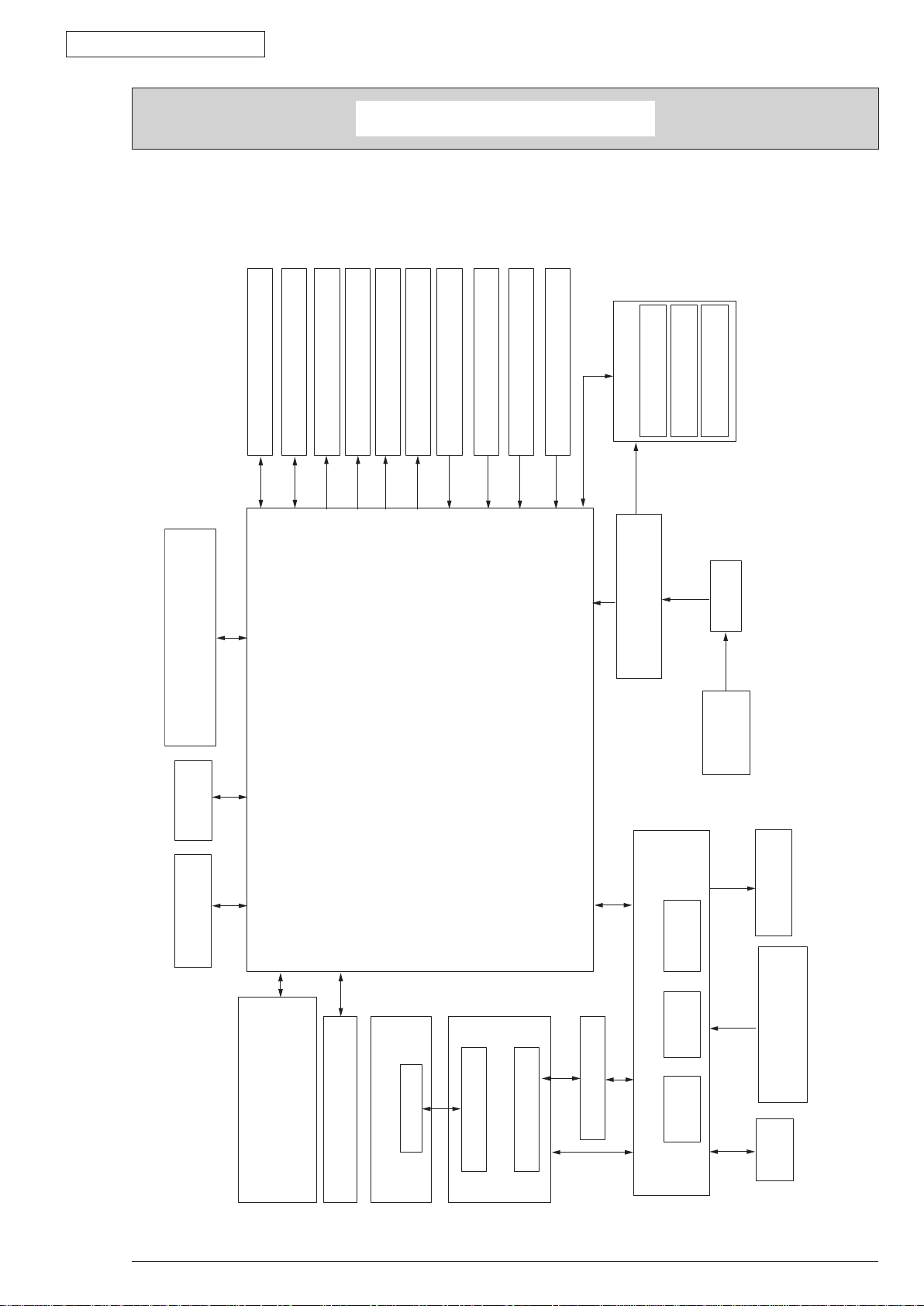
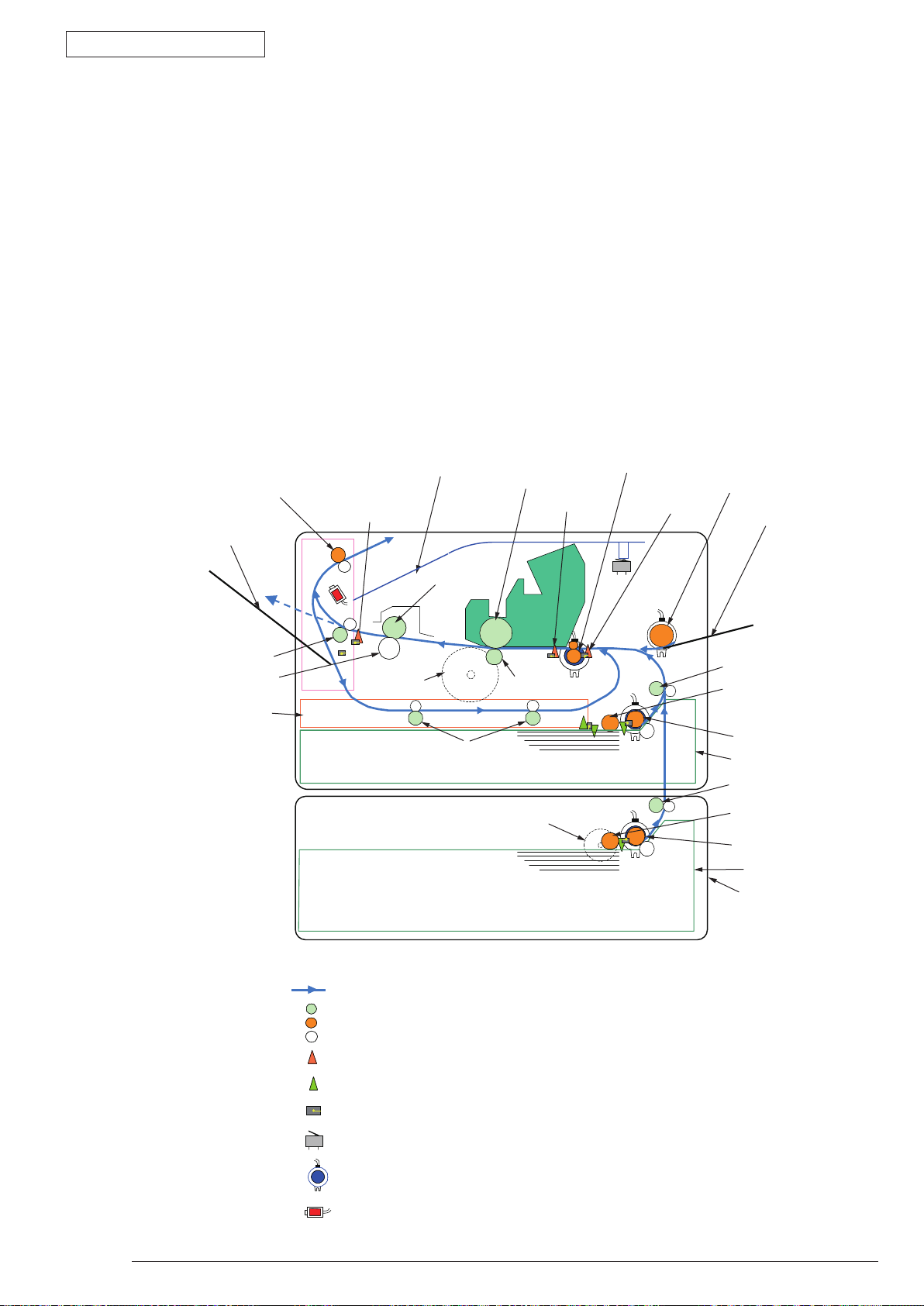
1.1 System Configuration
As the diagram 1.1 shows, for the standard configuration printer is configured by controller unit and
engine unit.
1. CONFIGURATION
1. CONFIGURATION
2nd tray unit*
Main DC Motor
LAN
(10BASE-T/100BASE-TX)
USB 2.0
Register clutch
Hopping clutch (1st)
Hopping clutch (MPT)
Solenoid for paper inverting
Main print circuit board
Paper end sensor
Cassette & Duplex detecting
Exit sensor
Rear cover open sensor
Fuser unit
Halogen lamp
Low voltage
power supply unit
FUSE
Temperature sensor
AC-SW
AC inlet
CENTRONICS
43984801TH
Rev.1
LCD:1, LED:2, SW:6
Operator panel board
LCD:1, LED:2, SW:1(B410d/B410dn)
LED head
(B420dn/B430d/B430dn)
Tag board
Toner cartridge
Tag transit board 3
Image drum cartridge
Figure1-1
Transfer roller
sensor
Toner inlet
WRT
sensor
Stacker cover open SW
High voltage power supply uint
IN
Tag transit board 1
Tag transit board 2
sensor
FAN
7 /
Page 8
Oki Data CONFIDENTIAL
A
A
A’
Paper cassette
Toner cartridge
High voltage
power board
Low voltage
power board
Image drum cartridge
A’
Stacker-Cover-Assy
Cover-Side-R
Cover-Side-L
Plate-Base-PCB
Plate-Assy-Base
Motor-Fan
Duplex
Rear-Cover-Assy
Fuser-Assy
OPE Cover-Assy
Guide-Paper-Duplex
Guide-Paper-R
Manual-Assy
Front-Guide-Assy
CU board
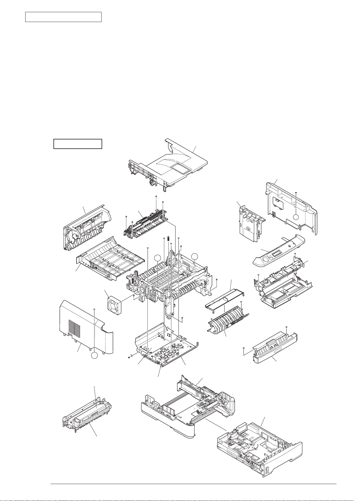
1.2 Printer Configuration
The printer main unit includes the following hardware parts.
• Electrophotographic processing part
• Paper feeding part
• Controller
• Op
erational part
• Power supply unit
•
Note!
The configuration of printer main unit is shown as diagram 1-2~1-4
B410d/B410dn
Fuser-Assy has to be replaced by Assy unit.
• It is forbidden to disassemble Fuser-Assy or reuse the disassembled Fuser-Assy.
1. CONFIGURATION
43984801TH
Rev.1
Figure1-2
8 /
Page 9
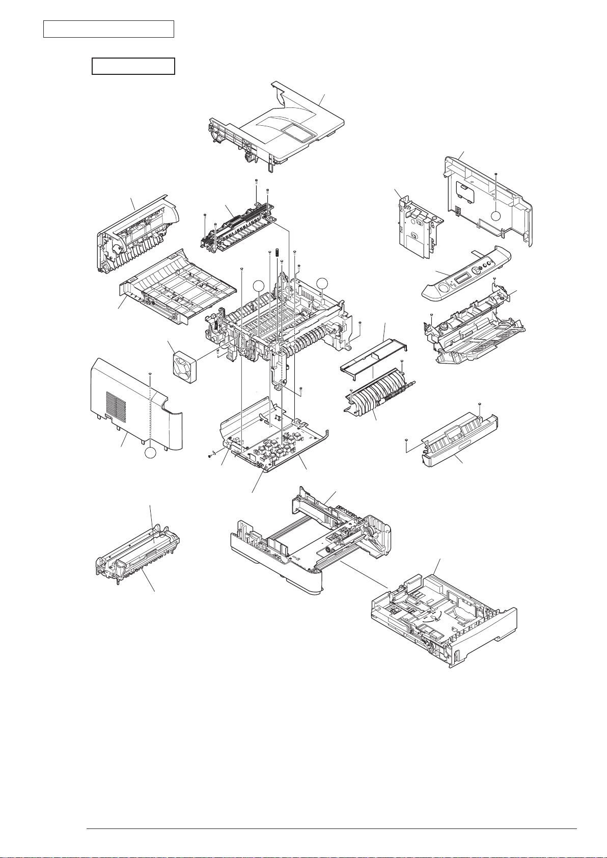
Oki Data CONFIDENTIAL
A
A
A’
A’
Stacker-Cover-Assy
Cover-Side-R
Cover-Side-L
Plate-Base-PCB
Plate-Assy-Base
Motor-Fan
Duplex
Rear-Cover-Assy
Fuser-Assy
OPE Cover-Assy
Guide-Paper-Duplex
Guide-Paper-R
MPT-Assy
Front-Guide-Assy
CU board
Paper cassette
Toner cartridge
High voltage
power board
Low voltage
power board
Image drum cartridge
B430d/B430dn
1. CONFIGURATION
43984801TH
Rev.1
Figure1-3
9 /
Page 10

Oki Data CONFIDENTIAL
B420dn
1. CONFIGURATION
Stacker-Cover-Assy
Cover-Side-R
Rear-Cover-Assy
Duplex
Cover-Side-L
Toner cartridge
Motor-Fan
A’
Fuser-Assy
Low voltage
power board
A’
High voltage
power board
A
Guide-Paper-Duplex
Plate-Base-PCB
Plate-Assy-Base
CU board
A
OPE Cover-Assy
MPT-Assy
Guide-Paper-R
Front-Guide-Assy
43984801TH
Image drum cartridge
Rev.1
Paper cassette
Figure1-4
10 /
Page 11
Oki Data CONFIDENTIAL
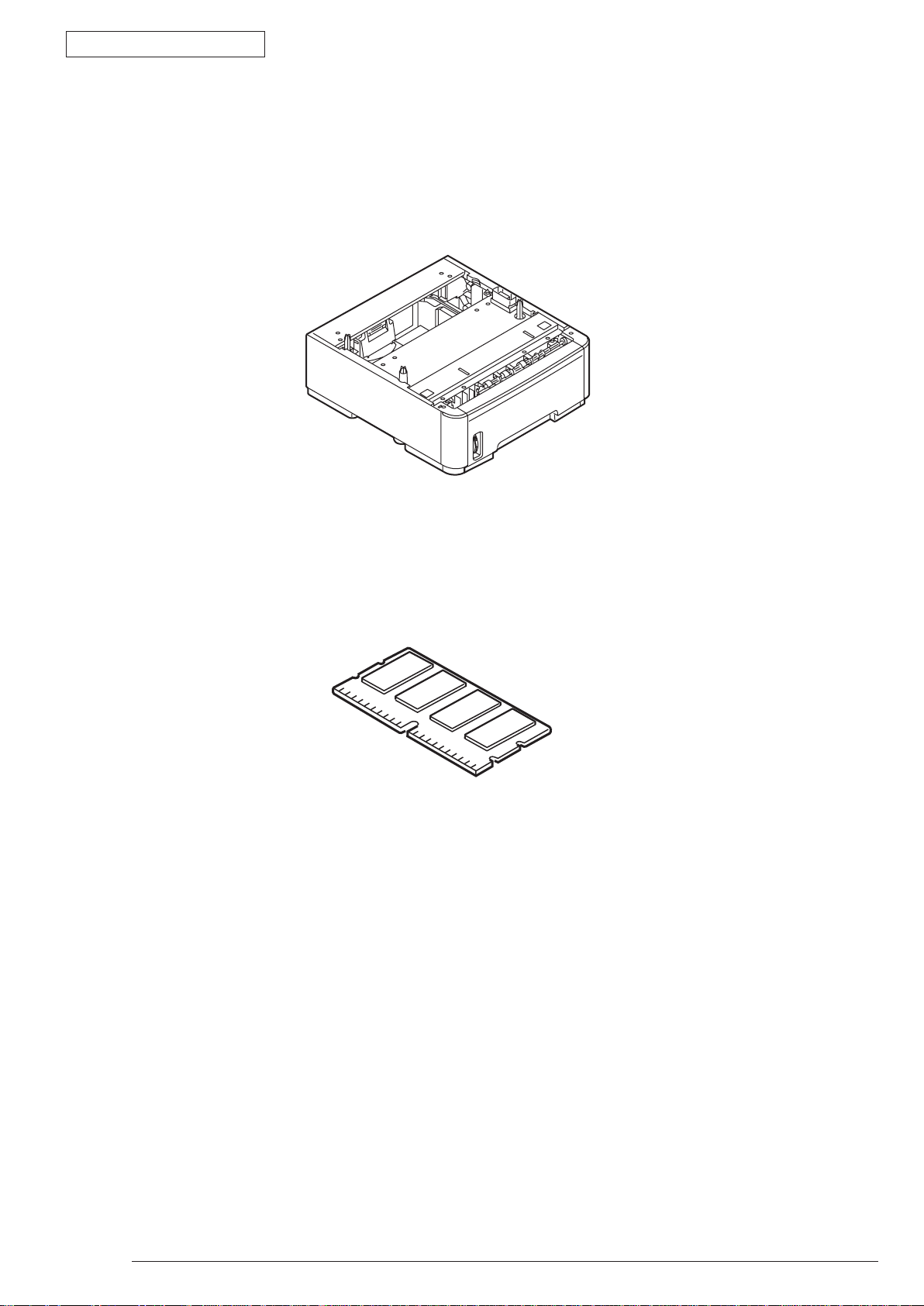
1.3 Optional Configuration
The options attached to the printer are as follows. These options can be ordered respectively for the
printer main unit.
(1) Second tray unit
1. CONFIGURATION
(2) Additionally installed memory (Domestic oriented printer only use 128MB.)
43984801TH
Rev.1
11 /
Page 12
Oki Data CONFIDENTIAL
1.4 Specification
(1) Type Desktop
(2) Dimension 268mm (Height) x 369mm (Width) x 395 (Depth)
:B41
297mm (Height) x 369mm (Width) x 395mm (Depth)
:B42
(3) Weight Approx. 10.6kg ( Including printer main unit & consumables.
Options, Feeding quantity of paper are excluded.)
1. CONFIGURATION
0d/B410dn/B430dn
0dn
(4) Development met
hod Dray type – Element developing method
Exposure method LED Head method
(5) Paper type, thickness, Size
Recommended paper Normal paper………….Excellent white A4
OHP Sheet…………….Sumitomo 3M CG3300
Label paper…………….Kokuyo LBP-A693
Category Size unit: mm (inch) Thickness
A4 Weig
A5
A6
B5
Letter
Normal Paper
Postcard
Envelope
Legal
Legal
Statement
Executive
h86~215.9
idt
Custom
Postcard Postcard
etu
rn Postcard
R
lope 1 (Chou #3) The envelope should be using 85g/m paper. The
Enve
lope 2 (Chou #4)
Enve
Envelope 3 (You #4)
W
Length 140~355.6
ht 55~105kg(64~120g/m2)
For double-side printing, weight55~90kg
2
(64~105g/m
Tray 1, Width 100~215.9, Length 210~355.6
Tray 2, Width 148~215.9, Length 210~355.6
flap of the envelope Chou type should not be with
fold, the flap of the envelope you should be clearly
folded.
The envelope should be using 24 lb. paper and
the flap part of it should be clearly folded.
)
Label Paper
OHP Sh
Part
ial Printing
Paper
Paper for Color
Printing
43984801TH
eet
Rev.1
Widt
Custom
Letter
Letter
h86~215.9
Length 140~355.6
ht 55~105kg(64~120g/m2)
Weig
Weight 55~105kg(64~120g/m
2
)
12 /
Page 13
Oki Data CONFIDENTIAL
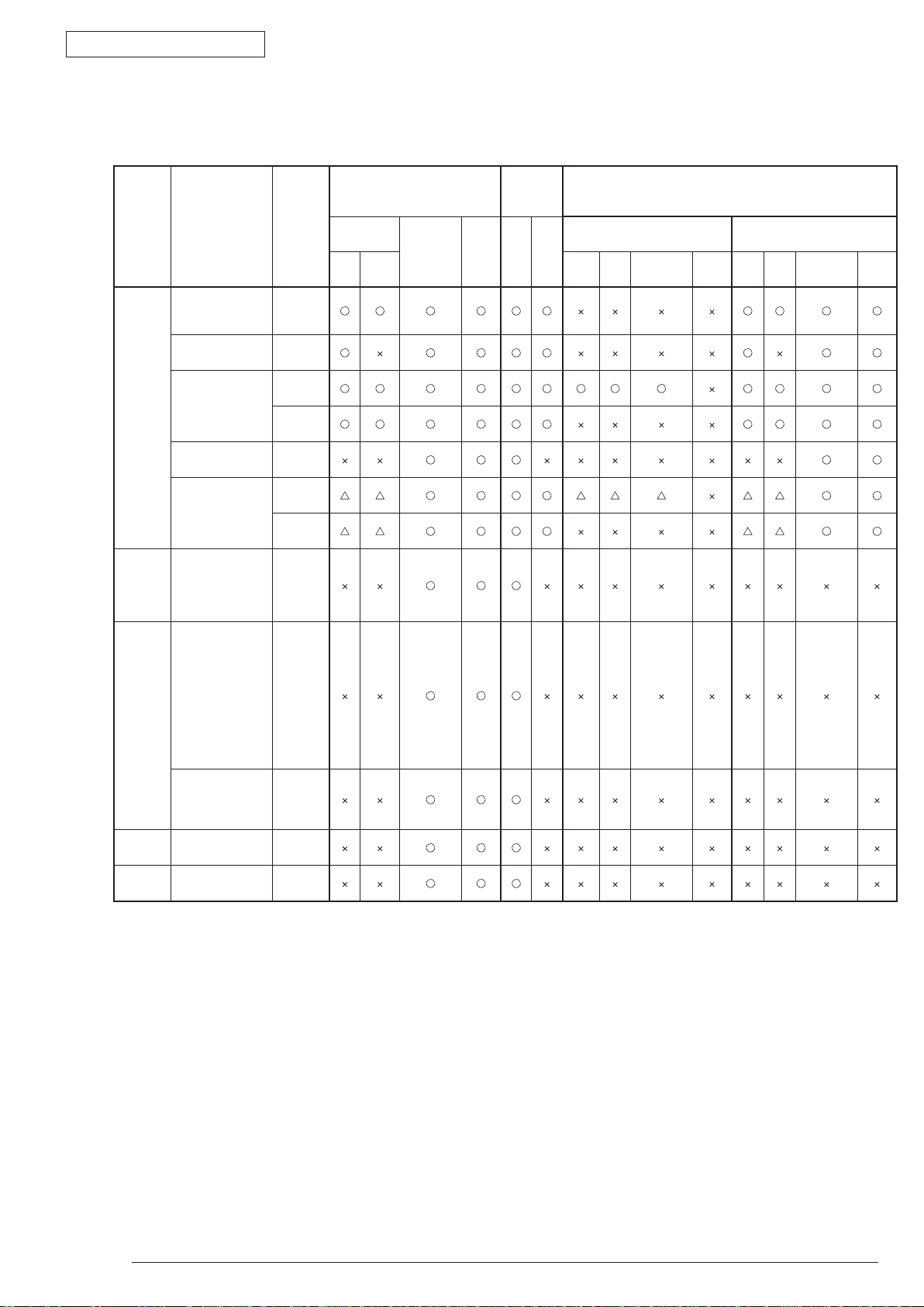
(6) Paper feeding method / Ejecting method
Type Size
5
A5 *
5
B5 *
Executive *
Statement *
A4
Normal
paper
Postcard
5
*
Envelope
5
*
Label
paper
OHP A4/Letter
Letter
Legal (13 inch)
Lega (14 inch)
A6 *
Custom *3 *
Width 86~215.9mm
Length
140~355.6mm
Postcard/
Return postcard
Envelope1 (CHOU
3
Envelope2
4
Envelope3
Com-9
Com-10
DL
C5
C6
Monarch
Custom
Width 86~215.9mm
Length
140~355.6mm
A4/Letter
5
5
5
5
)
)
CHOU
(
(YOU 4
Thickness
Weight
(
Weight
55~105kg
Weight
55~105kg
Weight
55~90kg
Weight
91~105kg
Weight
55~105kg
Weight
55~90kg
Weight
91~105kg
Postcard
or less
than
weight
135kg
)
6
*
6
*
0.1~
0.5mm
0.1~
0.5mm
Kg)
:
Tray
feeding Method
Paper
cassette
Tray
1
*
Paper
Multipurpose
2
4
tray *
1
Manual
Paper
ejecting
method
Face
up
Face
down
○
× :
△
double-side print *
Tray
Tray
1
1. CONFIGURATION
It is possible to use it.
:
It is not possible to use it.
It is possible to use it by a part of size
:
Double-side print
Automatic
Multipurpose
2
4
*
tray*
2
1
Manual Tray
1
Manual
double-side print
Multipurpose
Tray
2
4
*
tray *
1
Manual
*1: Multipurpose tray can be used for B420dn/B430dn.
2
*
: Face-up paper ejecting is not available at automatic double-side printing.
3
*
: Tray 1 is as width 100~21539mm, length 210~355.6mm. Tray 2 is as width 148~215.99mm, length 210~355.6mm.
4
*
: Tray 2 (The second tray unit) is for option.
5
*
: In case to set up the paper size for A5, A6, Postcard, Envelope, if the width of B5, Executive, Statement, Normal paper is less
than 200mm, also if thick paper or thicker paper has been set up for the paper thickness, the printing speed changes to be
slowly.
6
: • Envelope CHOU should be made by the paper or basis weight of 85g/m2 and without any fold on the flap part.
*
• Envelope YOU should be made by the paper of basis weight of 85g/m2 and with clear fold on the flap part.
• Com-9, Com-10, Monarch, C5, C6, and DL should be the envelope using 24lb paper and with clear fold on the flap part.
(7) Printing speed Continuous printing : Maximum 28 piece/second (A4, At copy mode, First try)
For Envelope • Postcard, if to enhance the printing quality, the
printing speed changes to be decreased.
For the resolution degree of 600 x 2400, if to enhance the
printing quality, the printing speed changes to be decreased.
W
43984801TH
Rev.1
arm up time : Approx. 25 second (25°C, 100V)
13 /
Page 14
Oki Data CONFIDENTIAL
10
28
32
Temperature (°C)
20 80
Relative humidity (%)
Up and running
(8) Paper feeding method Automatic feeding
(9) Paper ejecting method Face down (Rear ejecting) / Face up (Front ejecting)
(10) Resolution (Max.) 2400 × 600 dots / inch (B410d/B410dn/B420dn)
1200 × 1200 dots / inch (B430d/B430dn)
(11) Input electricity AC100V ± 10V, 50/60Hz ± 1Hz(B410dn/B430dn)
(12) Electricity consumption Up and running: Maximum 800W, Average 450W (25°C)
Ready and waiting: Average 70W (25°C)
Power-saving mode: (Without option) Under 6W
(With option) Maximum 7W
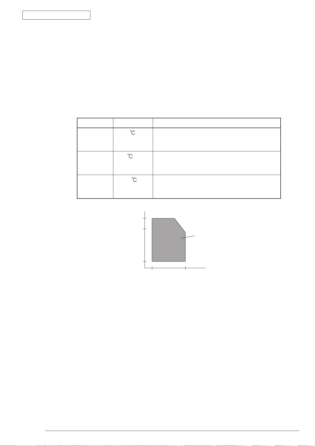
(13) Temperature and Humidity
1. CONFIGURATION
Tenperature Humidity
Up and
running
Power switch
off
Keeping
10~32
0~43
-10~43
20~80%RH (Relative Humidity) No condensation.
However, Maximum temperature of wet ball should
be 25°C.
10~90%RH (Relative Temperature) No
condensation. However, Maximum temperature of
wet ball should be 26.8°C.
10~90%RH (Relative Humidity) No condensation.
However, Maximum temperature of wet ball should
be 26.8°C.
(14) Operating noise In Printing : Rage A based on JIS Z9831, Average below 53dBA for SLOW.
Ready and waiting : Rage A based on JIS Z9831, Average below 53dBA for SLOW.
At power save : No sound (Background level)
(15) Consumables Toner cartridge : Approx. 3,500 piece /Approx. 7,000 piece/Approx. 10,000
printing paten. But, except the 1st Toner cartridge)
Imag
Cartridge : Approx. 20,000 piece (Single-side 3 pages/job) At Power save off.
Approx. 12,000 piece (Single-side 1 page/job) At Power save off.
43984801TH
Rev.1
piece(A4 ISO/IEC 19752 Continuous printing as
e drum : Approx. 25,000 piece (Continuously single-side printing of A4)
Approx. 7,000 piece (Single-side 1 page/job) At Power save on
(Minimum value)
.
14 /
Page 15
Oki Data CONFIDENTIAL
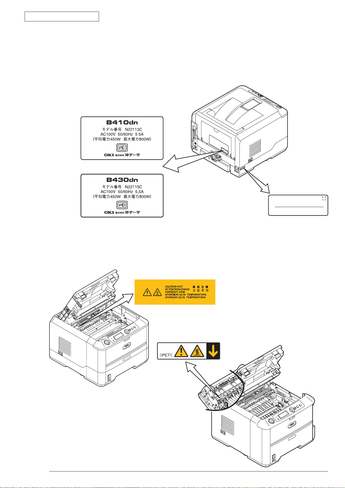
Serial No.
Made In China
B430dn
B410dn
1.5 Printing display
1.5.1 VCCI label, Serial No. label
The VCCI label and Serial No. label have been attached on the specified part of printer as shows
below.
1. CONFIGURATION
1.5.2 Warning label
Warning label has been attached on the part of printer that may cause injury to the operator.
Maintenance must be performed following the indication of the warning label.
43984801TH
Rev.1
15 /
Page 16
Oki Data CONFIDENTIAL
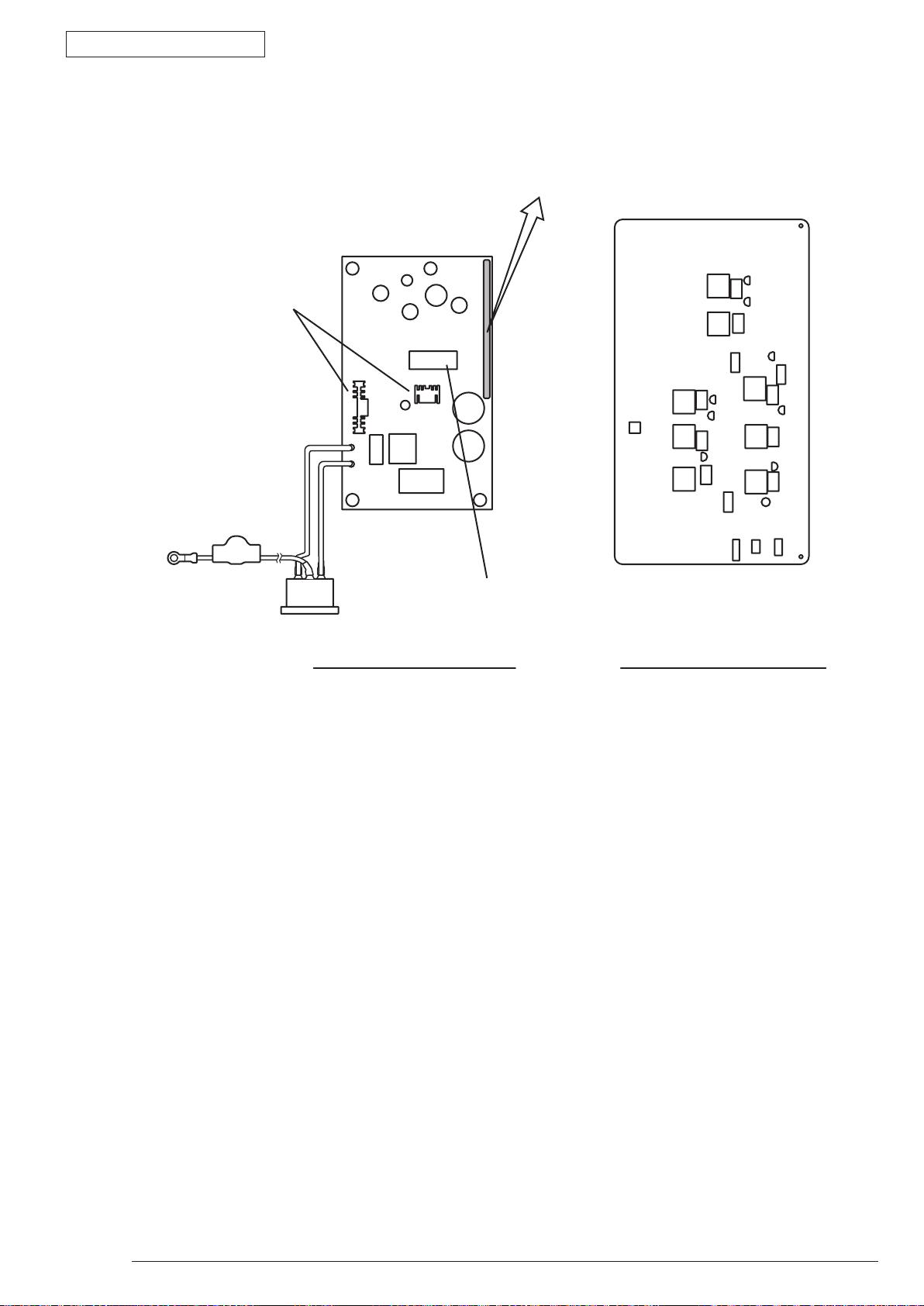
Low voltage power board
Warning / Caution content record
Heat sink
Transformer
High voltage power board
1.5.3 Warning / Caution display
The following warning / caution are displayed on the electrical power / sensor board.
1. CONFIGURATION
Note!
•
•
There is a risk of electric shock in the middle of the heat sink and transformer. Be sure to check
before touch it.
It may happen that the electricity has still left on the electrical circuit even after the fuse opened.
43984801TH
Rev.1
16 /
Page 17

Oki Data CONFIDENTIAL
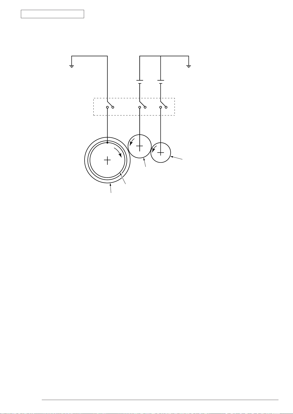
2.1 Electrophotographic process mechanism
(1) Electrophotographic process
The following describes the overview of electrophotographic process.
1. Charging
Equ
2. Exposure
The l
3. Development
Neg
ally charge the surface of image drum by applying negative voltage to the charged roller due to
negative charge.
ight from LED Head is exposed on the negative-charged surface of image drum. The surface
electrical potential of the exposed part of image drum surface becomes lower. Then forms electrostatic
latent image.
ative-charged toner is attracted to the electrostatic latent image due to electrostatic while touching
the image drum. Then forms viewable image.
2. Operational explanation
2. Operational explanation
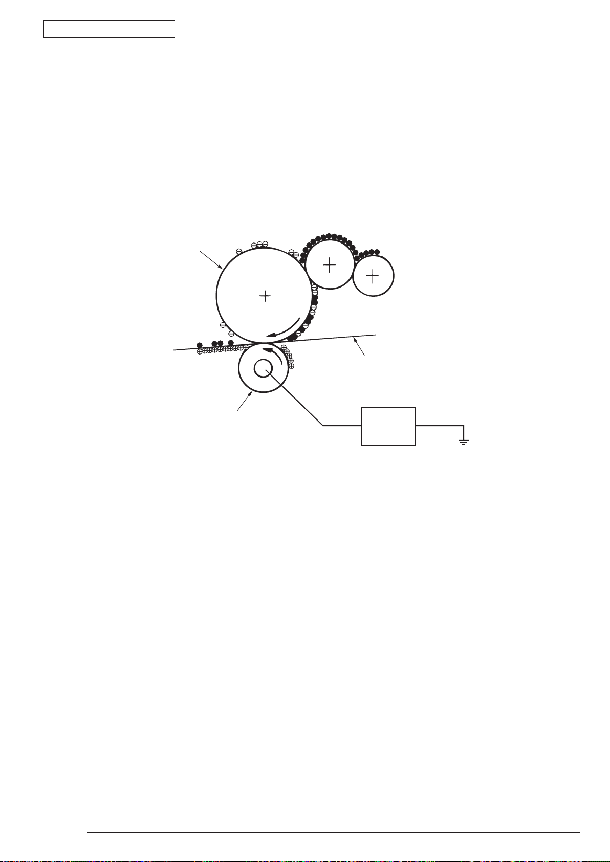
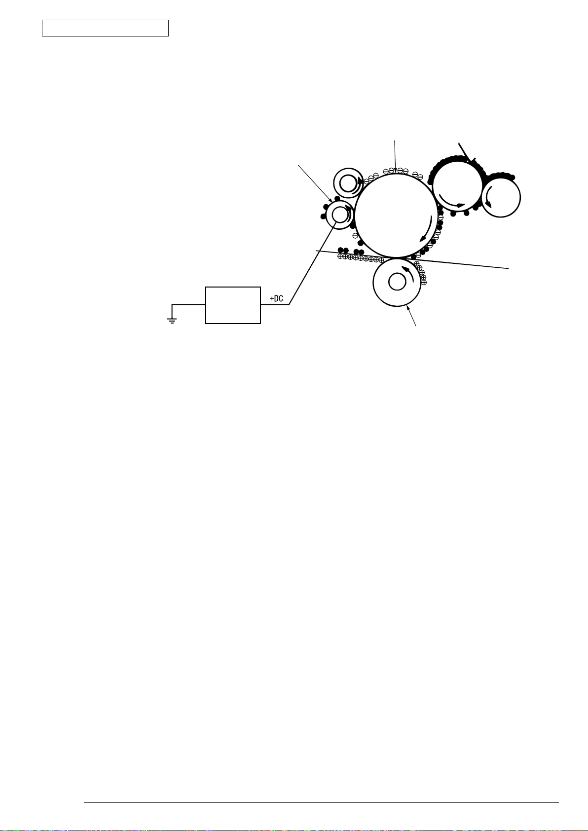
4. Transfer
Ove
5. Drum cleaning
The remaining toner on the image drum that is not transferred is made to be equable by cleaning roller.
6. Fusing
The t
rlap paper on the surface of OPC drum, from the backside of paper transfer toner image to the
paper by applying electrical charge by transfer roller.
And is temporarily attracted to the cleaning roller due to electrostatic.
oner image that is transferred to paper is fused on paper by heat and pressure.
43984801TH Rev.1
17 /
Page 18
Oki Data CONFIDENTIAL
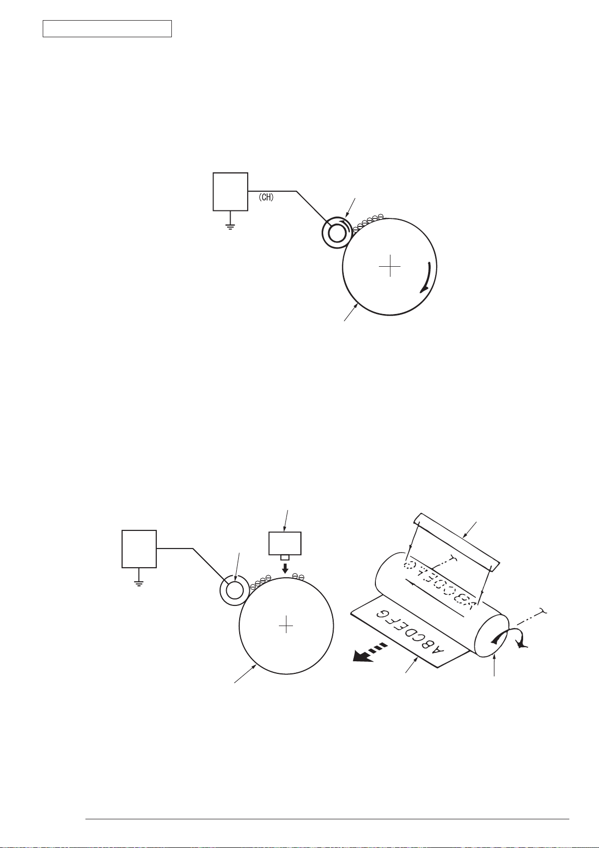
Image drum
Charged roller
Power
Charged roller
LED head
LED head
Image drum
Image drum
Paper
Power
1. Charging
Cha
rge the image drum surface by applying voltage to the charged roller that contacts the image drum
surface.
2. Operational explanation
2. Exposure
The light emitting from the LED Head will be exposed to the negative charged image drum. When the
surface electric potential of exposed part of the image drum goes to decrease, the electrostatic latent
image complying with image signal is formed.
Image drum is coated by basic layer (UL), charge generating layer (CGL), charge transferring layer (CTL)
on the basic material aluminum. The thickness of the organic light sensor (OPC) that is consisted by
CTL and CGL is approximate 20µm.
43984801TH Rev.1
18 /
Page 19
Oki Data CONFIDENTIAL
Image drum
Charged roller
Image developing plate
Toner supply roller
Image
developing
roller
3. Image development
Toner is attracted to the electrostatic latent image on the image drum surface, then the electrostatic
latent image changes to toner image.
1 As the roller on the supply spot of toner rotates while scrubbing the image-developing roller,
2. Operational explanation
fiction electricity occurs between the image developing roller and toner; toner is attracted to
the image-developing roller.
2. The toner that has been attracted to the image-developing roller is dropped down to the
developing plate to make a thin toner film on the image developing roller side.
3 The toner is attracted by the exposed part (Low electrical potential part) of the image drum
when the image drum contact the image developing roller, so as to see the electrostatic latent
image.
43984801TH Rev.1
19 /
Page 20
Oki Data CONFIDENTIAL
Image drum
Basic material
Toner feeding roller
While the cover is closed it will be
connected and bias will be applied.
Image developing roller
2. Operational explanation
Note! The ne
and image developing roller as show below.
cessary bypass voltage in image processing is impressed on the toner feeding roller
43984801TH Rev.1
20 /
Page 21
Oki Data CONFIDENTIAL
Image drum
Transfer roller
Paper
Power
4. Transfer
Th
As high plus voltage is applied to transfer roller from the power supply, the plus charge on the transfer
e transfer roller, which is from conductive sponge material, is created to meet intimate attachment
of image drum roller surface and feeding paper. The feeding paper is set up on the surface of image
drum. Plus charge, which is the converse polarity with toner polarity, is applied from the backside of the
paper.
roller surface is induced and transferred to the paper while the paper contact the transfer roller. The
negative charged toner, which has been attracted to the image drum surface, is transferred to the
surface of feeding paper by the plus charge of the backside of the paper.
2. Operational explanation
43984801TH Rev.1
21 /
Page 22
Oki Data CONFIDENTIAL
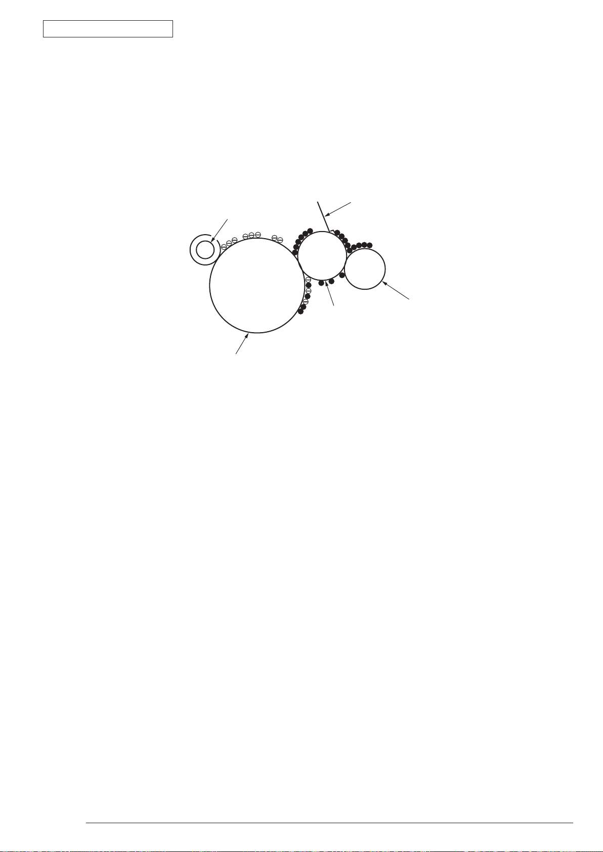
Power supply
Cleaning roller
Image drum
Transferring roller
5. Drum cleaning
1 Cleaning
After the completion of transferring, the remaining toner on the image drum is temporarily attracted
by the electrostatic and the image drum surface is cleaned.
2. Operational explanation
2 Roller cleaning
In the following case, there is a need of cleaning the charged roller, transfer roller, and cleaning roller.
•
Warming up as switching on the power supply
•
Warming up after open-close of the cover
•
In case of termination of printing operation
•
By periodically change the bias voltage that is implied to each roller during continuous printing,
transfer the attached toner from roller to image drum and then return it to developing device.
43984801TH Rev.1
22 /
Page 23
Oki Data CONFIDENTIAL
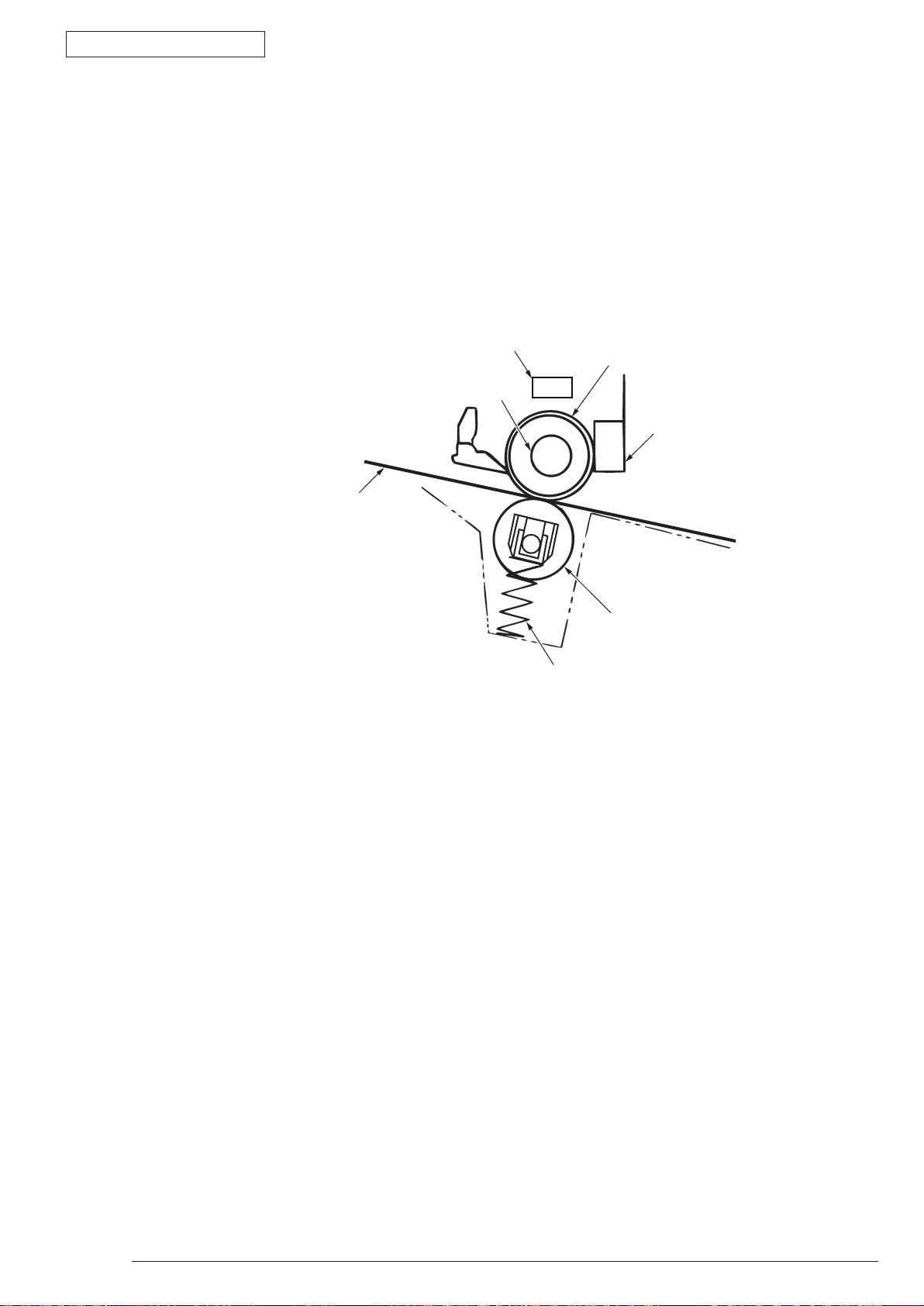
Separating clutch
Feeding paper
Heater
Heat roller
Thermistor
Backup roller
Pressuring spring
Thermostat
6. Fusing
Af
The thermistor that contacts the Heat roller adjusts the Heat roller temperature to the temperature
The back up roller is held by the pressure springs on each terminal due to the pressure applied.
ter the termination of transfer the unsettled toner image is settled to paper by heat and pressure
while passing between Heat roller and Back up roller. Heat roller is Teflon coated and is mounted by
heater that can generate heat (Halogen lamp).
specified by the menu complying with the paper width. For safety the thermostat shuts off the voltage
supply to the Heater by opening the thermostat in the case of abnormally temperature increasing.
2. Operational explanation
43984801TH Rev.1
23 /
Page 24
Oki Data CONFIDENTIAL
:
:
:
:
:
:
:
:
:
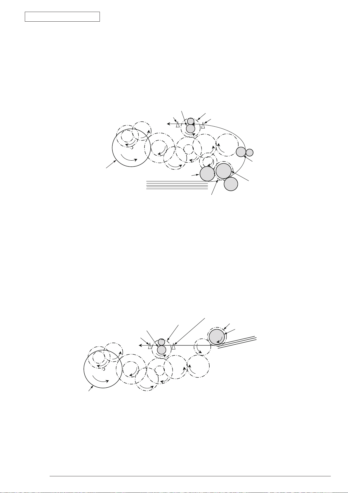
Face down stacker
Face up stacker
The 2nd ejecting roller
The 1st ejecting roller
Backup roller
Duplex unit
Ejecting
sensor lever
Resist roller
MPT feeding roller
Multipurpose tray
Conveying roller
Conveying roller
Transferring roller
Pulse motor
Paper conveying route
Driving roller (Continuous rotation)
Driving roller (Control rotation)
Driving roller
Paper level indicator lever
Indicating lever
Photo sensor
Micro switch
Magnetic clutch
Solenoid
DC motor
Heat roller
Conveying roller
Pick up roller
Pick up roller
Feeding roller
Feeding roller
Tray 1
Tray 2
2nd tray unit (option)
Entrance
sensor lever
Image drum
Writing out
sensor lever
2.2 Printing process
The paper fed from Tray 1 and Tray 2 is conveyed by feeding roller, conveying roller, and resist roller.
When feeding paper is from MPT, it is conveyed by MPT, feeding roller, and resist roller. After that the
feeding paper that is conveyed by image drum and the nip part of transfer roller forms toner image
on the paper through electrophotographic process. And then, the toner on the paper is fused by the
heat and pressure as the fuser unit passing through. The paper that fused the toner image is ejected
from the face down stacker of the ejecting roller. In the case of face up ejecting, it needs to open
the backside cover and install face up stacker. (It is unavailable for duplex printing while it is face up
ejecting.)
The above is about the operations at simplex printing, yet the below explains the operations at duplex
printing. While duplex printing, the paper, which firstly passed through the fuser unit after the backside
printing, is conveyed to the inward of Duplex Unit, by the reverse operation of the second ejecting roller
that is a certain time after removing the first ejecting roller of the paper rear side. Paper, is conveyed by
conveying roller of Duplex Unit, and then merges to the same route with the feeding paper that is from
the tray. Onwards, it is the same with the simplex printing operation by the feeding paper from tray.
2. Operational explanation
43984801TH Rev.1
24 /
Page 25
Oki Data CONFIDENTIAL
Resist roller
Resist clutch
Entrance sensor lever
Conveying roller
Paper feeding roller
Pick up roller
DC motor
(Counterclockwise rotation)
Paper feeding clutch
Paper
Writing out sensor lever
Resist clutch
Writing out sensor lever
Resist roller
Entrance sensor lever
Paper feeding clutch
MPT paper feeding roller
Paper
DV motor
(Counterclockwise rotation)
(1) Paper feeding from Tray 1
1. As DC motor rotating (Counterclockwise rotation), if set the paper feeding clutch as ON, as the
paper feeding roller and pick up roller rotating, the paper that is inside the tray is conveyed.
2. The paper is conveyed by the conveying roller. After the entrance sensor level set to be ON, it
bumps into the stopping resist roller, a certain more amount of paper is conveyed. (This corrects
the paper skew.)
3. If set the resist clutch as ON, the paper is conveyed by resist roller.
2. Operational explanation
(2) Paper feeding from Multipurpose tray (MPT)(B420dn, B430d, B430dn)
1. As
DC motor rotating (Counterclockwise rotation), if set paper feeding clutch as ON the MPT paper
feeding roller starts to rotate, the paper in the tray is conveyed.
2. After setting th
more amount of paper is conveyed. (This corrects the skew of paper.)
3. If set the r
e entrance sensor lever as ON, the paper bumps into the stopping resist roller, a certain
esist clutch as ON, the paper is conveyed by resist roller.
43984801TH Rev.1
25 /
Page 26
Oki Data CONFIDENTIAL
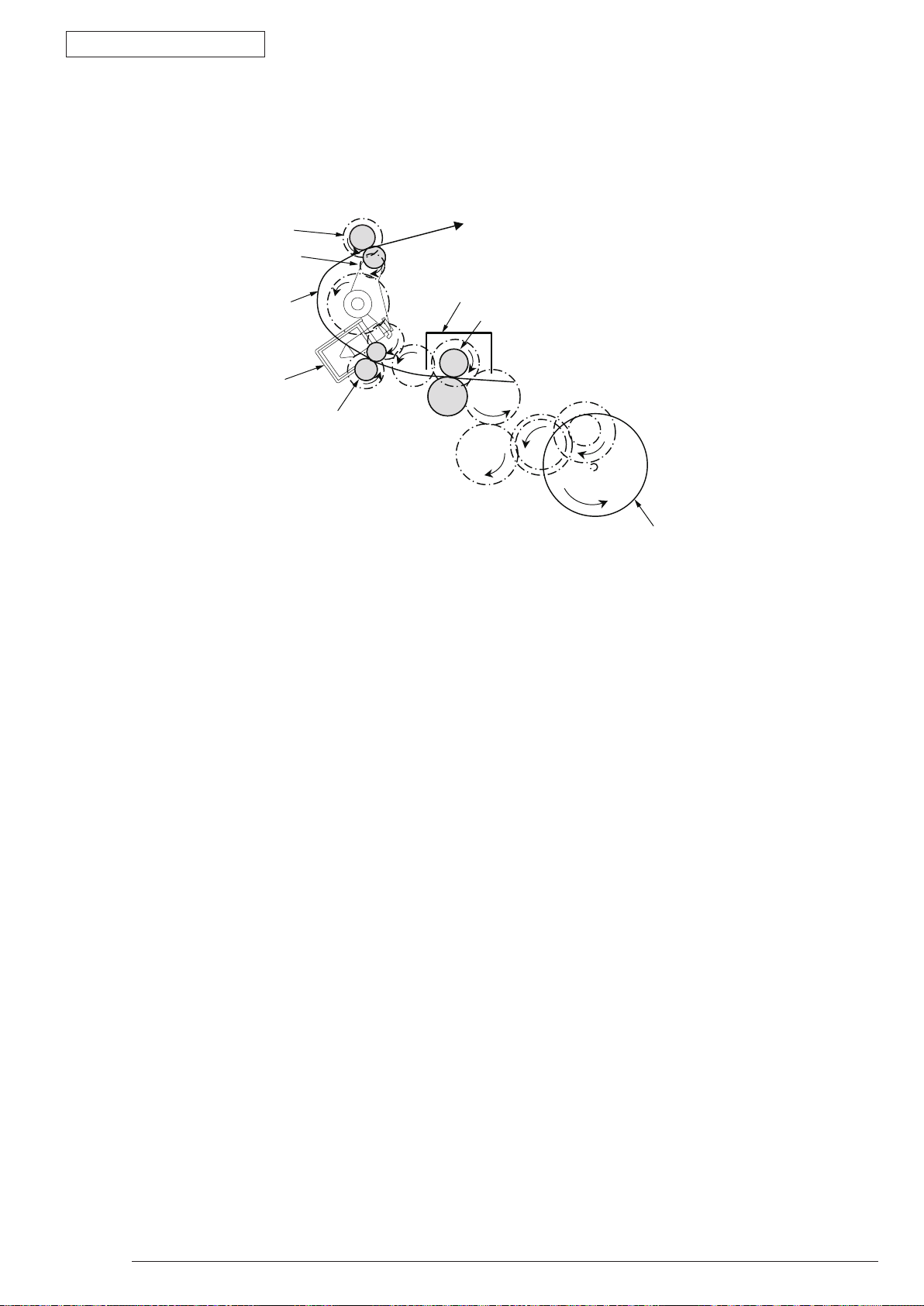
Eject roller
Eject roller
Planet gear
Paper route
Solenoid
Fuser unit
Heat roller
DC motor
(Counterclockwise rotation)
(3) Fuser unit and paper ejecting
2. Operational explanation
1. The fuser u
2. Simultaneously th
nit and eject roller is
e eject roller rotates, and then the paper is ejected.
43984801TH Rev.1
26 /
Page 27
Oki Data CONFIDENTIAL
Fuser unit
Fuser unit
Heat roller
Heat roller
DC motor
(Counterclockwise rotation)
DC motor
(Counterclockwise rotation)
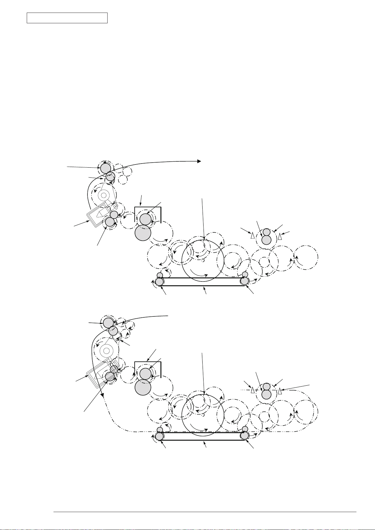
Resist roller
Resist roller
Resist clutch
Resist clutch
Resist Entrance
sensor lever
Resist Entrance
sensor lever
Duplex conveying roller
Writing out
sensor lever
Writing out
sensor lever
Duplex conveying roller
The 1st ejecting roller
The 1st ejecting roller
The 2nd ejecting
roller
The 2nd ejecting
roller
Planet gear
Planet gear
Solenoid
(OFF)
Solenoid
(ON)
[ Normal rotation ]
[ Inverse rotation ]
Belt
Duplex conveying rollerDuplex conveying roller
Belt
(4) Paper reversing and paper multi-feeding
2. Operational explanation
1. TRemoving th
planet gear starts to move, the second eject roller starts inverse rotating (Counterclockwise rotation).
2. By the i
3. Paper is c
4. After setting t
more amount of paper is conveyed. (This corrects the skew of paper.).
5. If set t
he Resist clutch as ON, paper is conveyed by Resist roller.
e first eject roller at the rear part of paper and set the solenoid as ON for a while, then the
nverse rotation of the second eject roller the paper is inversely rotated and conveyed to Duplex.
onveyed by Duplex conveying roller.
he entrance sensor lever as ON, paper bumps into the stopped resist roller, still a certain
43984801TH Rev.1
27 /
Page 28
Oki Data CONFIDENTIAL
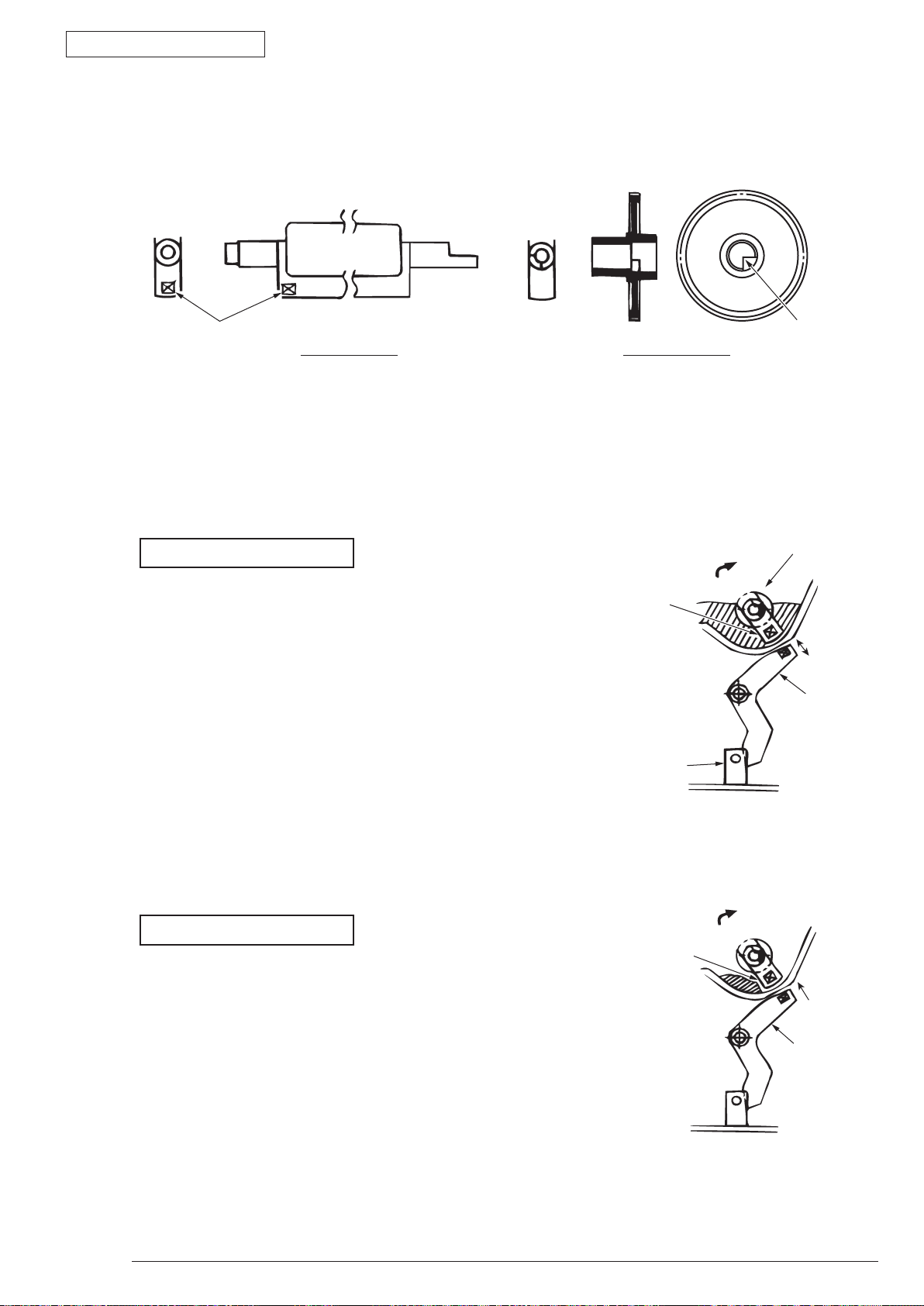
Magnet
Agitating bar Agitating gear
Crack part
Agitating bar
Agitating bar
Agitating gear
Sensor plate
Sensor plate
Toner sensor
2.3 Toner entrance detection
• Equipment
Toner entrance detecting equipment consists the agitating gear that agitating the agitating bar at a
certain speed and magnet that is on the agitating bar.
•
Operation
Detecting the toner low by monitoring the congruous time intervals between the magnet that is set on
the sensor plate and the magnet attached on the agitating bar,
2. Operational explanation
Operation in toner full status
•
The crack part of agitating gear meshing with the
projection portion of agitating bar, the agitating bar
rotates in accordance with the rotating of gear.
•
Even after the magnet part of the agitating Bar reaches
the highest position, it still rotates at the same speed
by the pressure of the agitating gear due to the toner
resistance.
Operation in toner low status
•
When the magnet part of the agitating bar reaches the
highest position, because there is no resistance from
toner, the agitating bar drops earlier than the gear by
the gravity itself, and stops by that status.
For this reason, the time that the magnet of agitating
Bar magnetic attracts the magnet of sensor plate
becomes longer. The toner low status can be inspected
by monitoring this time.
43984801TH Rev.1
28 /
Page 29

Oki Data CONFIDENTIAL
Toner full status
Toner low status t1 t2 t1,t2: Magnet attracting time
• Toner sensor alarm actuates if there is not any change on toner sensor.
• Toner sensor is not monitored while main (drum) motor is stopping.
2. Operational explanation
43984801TH Rev.1
29 /
Page 30
Oki Data CONFIDENTIAL
OFF
ON
Shutting
off
Reconnecting
Earth cable
Earth terminal
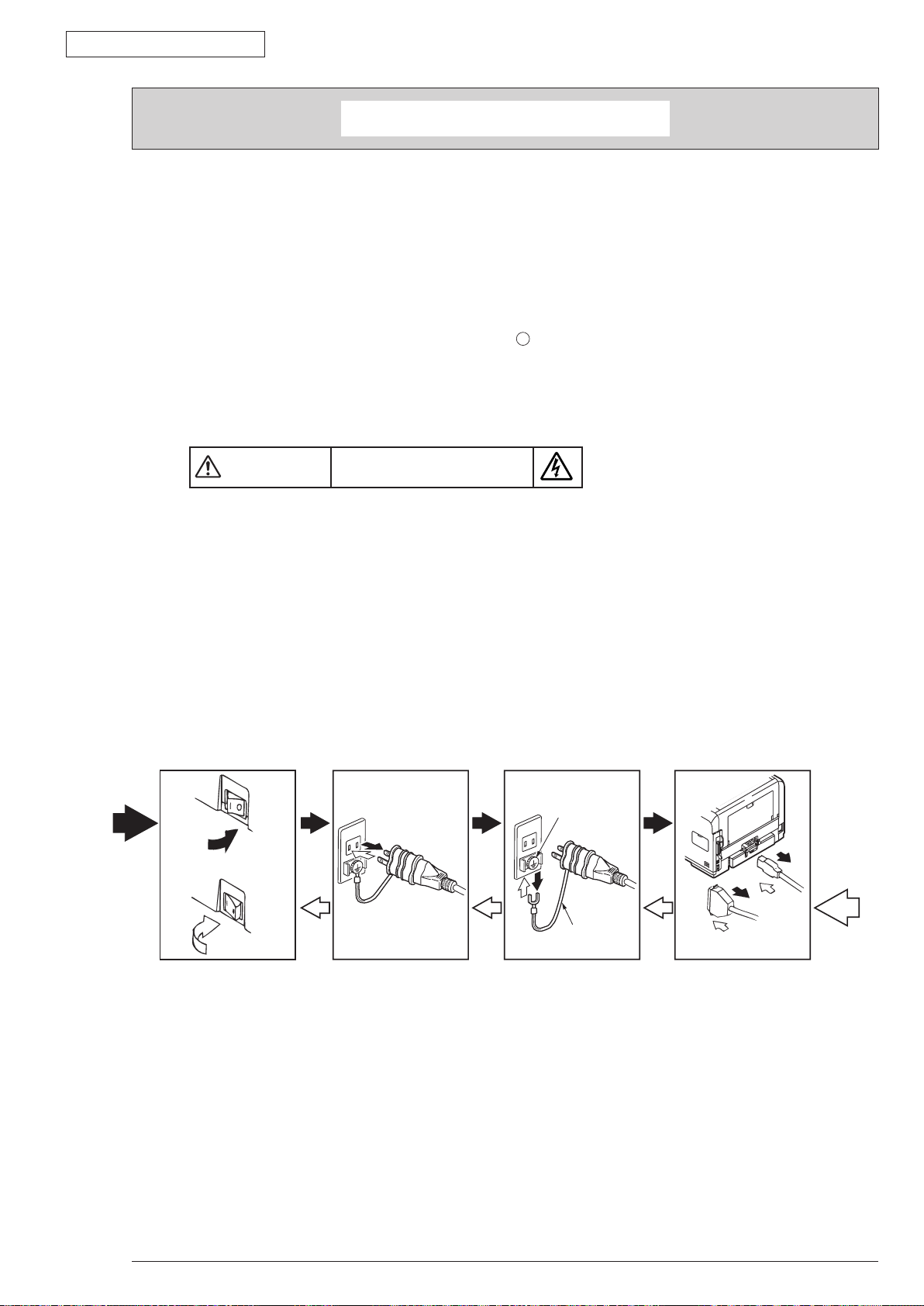
Warning
This section explains the replacement procedure of part, assembly, and unit in the working place.
Disassembling procedure relating to reassembling is conducted conversely.
3.1 Preparation for parts replacement
(1) Be sure to unplug the AC cord and interface cable before starting to replace parts.
(a) Unplugging the AC cord by the following procedures.
i) Shut off the power switch of the printer. (
ii) Unplug the AC insert plug of AC cord from the AC socket.
iii) Remove the earth wire from AC socket.
iv) Unplug the AC cord and interface cable from printer.
3. Parts replacement
)
」
「
Risk of Electric Shock
3. Parts replacement
There is a risk of electric shock during replacement of the low voltage power supply.
Use insulating gloves or avoid direct contact with any conducting part of the power supply, and caution should be
exercised during replacement.
The capacitor may take one minute to complete discharge after the AC cord is unplugged. Also, there is a possibility
that the capacitor doesn’t discharge because of a breakage of the PCB, etc., so remember the possibility of electric
shock to avoid electric shock.
(b) Reconnecting the printer by the following procedures.
i) Connect the AC cord and interface cable to the printer.
ii) Connect earth wire to the AC socket.
iii) Connect the AC insert plug to the AC socket.
iv) Turn on the power switch of the printer. (
「I」
)
(2) Do not disassemble the printer in the case of normal operation.
(3) Do not disengage the part that there is not any necessary to touch. Disassembly should be the
(4) B
(5) Be sure to temporarily install the small part such as screw, collar, and so on at its original position during
(6) D
(7) D
(8) Do not put the Print Circuit Board on the printer of on the floor directly.
43984801TH Rev.1
minimum.
e sure to use the specified maintenance tools.
disassembling because it is easy to be lost.
o not use the gloves that is easy to occur electrostatic while dealing with IC such as micro-sensor,
ROM, RAM, etc. and PCB.
o not put the print circuit board on the equipment or on the floor directly.
30 /
Page 31

Oki Data CONFIDENTIAL
[Maintenance tools]
The necessary tools for replacing the print circuit board, assembly, and unit is shown as graph 3-1.
No. Maintenance tools Quantity Application Remark
3. Parts replacement
Graph 3-1 Maintenance tools
1
2
3
4
5
6
7
Note! Use vacuum by the type that applying to toner. It may cause fire if use normal vacuum.
No.2-200 + Magnetic driver 1
No.3-100 Driver 1
No.5-200 Driver 1
Digital multi-meter 1
Pliers 1
Handy cleaner 1
E ring pliers 1
3~5mm
Screw
For E ring
removing
Refer to the
following Note!
43984801TH Rev.1
31 /
Page 32

Oki Data CONFIDENTIAL
A
A
A’
A’
Stacker-Cover-Assy
Cover-Side-R
Cover-Side-L
Plate-Base-PCB
Plate-Assy-Base
Motor-Fan
Duplex
Rear-Cover-Assy
Fuser-Assy
OPE Cover-Assy
Guide-Paper-Duplex
GuidePaper-R
Manual-Assy
Front-Guide-Assy
CU board
Toner cartridge
Low voltage
power board
High voltage
power board
Paper cassette
Image drum cartridge
3.2 Parts layout
This section explains the main parts layout of the equipment.
B410d/B410dn
3. Parts replacement
43984801TH Rev.1
Figure 3-1
32 /
Page 33

Oki Data CONFIDENTIAL
A
A
A’
A’
Stacker-Cover-Assy
Cover-Side-R
Cover-Side-L
Plate-Assy-Base
Motor-Fan
Duplex
Rear-Cover-Assy
Fuser-Assy
OPE Cover-Assy
Guide-Paper-Duplex
GuidePaper-R
MPT-Assy
Front-Guide-Assy
CU board
Plate-Base-PCB
Toner cartridge
Low voltage
power board
High voltage
power board
Paper cassette
Image drum cartridge
B430d/B430dn
3. Parts replacement
43984801TH Rev.1
Figure 3-2
33 /
Page 34

Oki Data CONFIDENTIAL
B420dn
3. Parts replacement
Stacker-Cover-Assy
CU board
Rear-Cover-Assy
Duplex
Cover-Side-L
Motor-Fan
A’
Low voltage
power board
Fuser-Assy
Toner cartridge
A’
GuidePaper-R
Plate-Base-PCB
High voltage
power board
A
Plate-Assy-Base
Cover-Side-R
A
OPE Cover-Assy
MPT-Assy
Guide-Paper-Duplex
Front-Guide-Assy
Image drum cartridge
43984801TH Rev.1
Paper cassette
Figure 3-3
34 /
Page 35

Oki Data CONFIDENTIAL
Photo Interrupter
Roller-Pick-Up
Roller-Feed-Now
Guide-Cassette-L
Guide-Cassette-R
Plate-Base
Gear-Assy-Clutch
[Base unit]
B410d/B410dn/B430d/B430dn
3. Parts replacement
43984801TH Rev.1
Figure 3-4
35 /
Page 36

Oki Data CONFIDENTIAL
[Base unit]
3. Parts replacement
B420dn
Photo Interrupter
Gear-Assy-Clutch
Roller-Pick-Up
Roller-Feed-Now
Plate-Base
Guide-Cassette-L
(530sht)
Guide-Cassette-R
(530sht)
Figure 3-5
43984801TH Rev.1
36 /
Page 37

Oki Data CONFIDENTIAL
Cover Side-R
(3.3.3)
Cover Side-L
(3.3.6)
CU Board
(3.3.5)
Motor-DC-Main
(3.3.6)
Rear-Cover-Assy
(3.3.15)
OPE Cover Assy
(3.3.5)
Stacker-Cover-Assy
(3.3.13)
Ope Board
(3.3.8)
MPT-Assy
(In case of B410dn, it is Manual-Assy)
(3.3.9)
Front-Guide-Assy
(3.3.10)
Roller-Assy-Feed
(3.3.11)
Guide -Paper-Duplex
(3.3.12)
Fuser-Assy
(3.3.14)
Frame-Assy-Lower
(3.3.16)
Plate-Brecket-Motor
(3.3.18)
Roller-BackUP
(3.3.19)
Roller-Regist
(3.3.20)
Lever-In-Sensor
(3.3.21)
Lever-Eject-Sensor/Photo-Interrupter
(3.3.22)
Lever-End/Lever-Duplex/
Lever-Cassette/Gear-Assy-Clatch
(3.3.23)
PR Unit
LED Head
(3.3.1)
High/Low voltage Power Board
(3.3.17)
Paper Feeding Roller (Roller-Pick-Up,Roller-Feed-NOW,Roller-Assy-MPT)
(3.3.24)
3.3 Parts replacement method
This section explains the replacement method of the parts and assemblies that are shown in the following
disassembling diagram.
About the parts replacement procedure, the parts that are shown by parts number using white number in the
are the RSPL parts.
The explaining diagram of parts replacement procedure is B430dn.
Replace part after performing the following operation.
(1) Unplug the AC power cord from the main unit inlet by the disconnected status of power switch.
(2) Unplug the interface cable from the main unit.
3. Parts replacement
43984801TH Rev.1
37 /
Page 38

Oki Data CONFIDENTIAL
Stacker-Cover-Assy
Cable
Hook B
Hook A
SLA
(Selfoc Lens Array)
3.3.1 LED Head
(1) Open the Stacker-Cover-Assy
(2) Remove the 2 screws (Black)
(3) Firstly open Hook A by narrow direction and then remove it. Secondly remove Hook B then remove LED
Assy
(4) Remove cable from the connector of LED Assy
(5) Installing is performed by the reverse procedure with removing.
Note! Beware of not to touch or press the SLA parts of LED Head directly.
. (At this moment, the 2 springs can be also removed jointly.)
3. Parts replacement
. Remove Holder-Head .
.
43984801TH Rev.1
38 /
Page 39

Oki Data CONFIDENTIAL
Stacker-Cover-Assy
Latch
③
❶
②
❷
❶
3.3.2 Roller-Transfer
(1) As the power switch shut off, unplug the AC power cord from the inlet of main unit.
(2) Open the Stack-Cover –Assy
(3) Remove latches in the 2 places of Gear-TR
any unnecessary pressure while removing the latch.)
lightly slide the Roller-transfer ❷ to the right side and remove the post on the top of gear from the
(4) S
contact of Frame-Assy-Lower. Remove the latches on the 2 places of Gearing-TR❶ of Gear.
(5) H
old the Bearing-TR ❶on the both side, and then lift up the Roller-Transfer ❷. (At this moment, Gear-
TR ③ is also removed.)
(6) I
nstalling is performed by the inverse procedure with removing.
(Note on removing / installing)
eware of not to touch the DC motor inattentively (Do not rotate motor).
1. B
2. While installing, pay attention to the up-and-down direction of Bearing-TR
3. O
perating carefully, not to touch Roller-Transfer ❷ surface.
3. Parts replacement
and Bearing-TR ❶ on the conversing side. (Do not add
③
❶.
43984801TH Rev.1
39 /
Page 40

Oki Data CONFIDENTIAL
Rear-Cover-Assy
Stacker-Cover-Assy
①
②
③
3.3.3 Cover-Side-R
(1) As the power switch shut off, unplug the AC power cord from the inlet of main unit.
(2) Unplug the interface cable from the main unit.
(3) Open the Rear-Cover-Assy.
(4) Open the Stacker-Cover-Assy.
(5) Take out the image drum cartridge.
(6) Remove the Cover-Access
(7) R
emove the screw (Black) ②. Remove the Cover-Side-R ③.
(8) I
nstalling is performed by the inverse procedure with removing.
(Note on removing / installing)
eware of not to touch the DC motor inattentively (Do not rotate motor).
1. B
①
3. Parts replacement
.
43984801TH Rev.1
40 /
Page 41

Oki Data CONFIDENTIAL
②
Stacker-Cover-Assy
Rear-Cover-Assy
①
3.3.4 Cover-Side-L
(1) As the power switch shut off, unplug the AC power cord from the inlet of main unit.
(2) Unplug the interface cable from the main unit.
(3) Open the Rear-Cover-Assy.
(4) Open the Stacker-Cover-Assy.
(5) Take out the image drum cartridge.
(6) Remove the 2 screws (Black)
(7) Installing is performed by the inverse procedure with removing.
Note! Attach the Label Motor-Fan on the outside that is obviously to be seen.
3. Parts replacement
. Remove Cover-Side-L .
43984801TH Rev.1
41 /
Page 42

Oki Data CONFIDENTIAL
②
①
⑥
④
⑤
③
⑦
⑨
⑦
DC motor
③
⑤
❽
3.3.5 CU Board
(1) Remove the Cover-Side-R. (Refer to 3.3.3)
(2) Remove the 4 pieces of screws (Silver) ①. Remove the Plate-Cover-Shield-CU ②.
3. Parts replacement
(3) Remove the 2 pieces of big screws (Silver) ③. Remove the Film-Core-Holder ④. In the meantime
remove the cable connector (with core) ⑤ together.
(4) Remove the 2 pieces of small screws (Silver) ⑥, 2 pieces of big screws (Silver) ⑦, and cable
connector from the CU board ❽. Remove the Spring-FG-Solenoid ⑨ and CU board ❽.
(5) I
nstalling is performed by the inverse procedure with removing.
(Note on removing / installing)
eware of not to touch the DC motor inattentively (Do not rotate motor).
1. B
eware of not to tuck down the cable while installing the Plate-Cover-Shield-CU ②.
2. B
43984801TH Rev.1
42 /
Page 43

Oki Data CONFIDENTIAL
❹
③
⑤
②
①
Cable
3.3.6 Motor-DC-Main
(1) Remove the Cover-Side-R. (Refer to 3.3.3)
(2) Remove the Plate-Cover-Shield-CU. (Refer to 3.3.5(2))
(3) Remove the connector
ut the TY-RAP that is bundling the cable of Motor-DC-Main and the cable of Resist clutch.
(4) C
(5) Remove the 3 pieces of screws (Silver)
emove the Motor-DC-Main ❹. Unplug the cable from the Piece-Guide ⑤.
(6) R
(7) I
nstalling procedure is performed by the opposite order with removing. Bundle the cable of Motor-DC-
Main and the cable of Resistor clutch by TY-RAP.
(Note on removing / installing)
1. Beware of not to touch the DC motor inattentively (Do not rotate motor).
of Motor-DC-Main from CU board.
①
and the 1 piece of screw (Black) ③.
②
3. Parts replacement
43984801TH Rev.1
43 /
Page 44

Oki Data CONFIDENTIAL
①
②
③
CU board
Stacker-Cover-Assy
Rear-Cover-Assy
Cover-Assy-MPT
❹
Claw A
Claw B
Claw B
3.3.7 OPE Cover-Assy
(1) Open the Rear-Cover-Assy.
(2) Open the Stacker-Cover-Assy.
(3) Remove the Cover-Side-R and Cover –Side-L. (Refer to 3.3.3/3.3.4)
(4) Remove the Plate-Cover-Shield-CU. (Refer to 3.3.5(2))
(5) Remove the screw (Silver)
emove the FFC cable ③ from the CU board.
(6) R
(7) O
pen the Cover-Assy-MPT.
(8) Pull Claw A by the arrow direction. Remove the clamp by pushing Claw B as the arrow direction.
Remove the OPE Cover-Assy ❹.
nstalling is performed by the reverse procedure with removing.
(9) I
(Note on removing / installing)
eware of not to touch the DC motor inattentively (Do not rotate motor).
1. B
. Remove the Film-Core-Holder ②.
①
3. Parts replacement
43984801TH Rev.1
44 /
Page 45

Oki Data CONFIDENTIAL
Claw
Claw
Cover-OPE
④
③
①
②
3.3.8 Ope-Board
(1) Remove OPE Cover-Assy. (Refer to 3.3.7)
(2) Remove Ope-Board ① from Cover-OPE by pulling the claw as the arrow direction.
(3) U
nplug FFC cable ② from Ope-Board ①.
(4) R
emove Button-KEY ③ and Lens-LCD ④ from Ope-Board ①.
(5) I
nstalling is performed by the reverse procedure with removing.
3. Parts replacement
43984801TH Rev.1
45 /
Page 46

Oki Data CONFIDENTIAL
A
A
B
B
Driver
Pay attention not to let Separating- Pad- Assy pop out to
your front side while installing MPT-Assy.
C
Frame-Assy-Lower
❹
❹ʼ
②
②
②
②
③
①
③
3.3.9 MPT-Assy (In case of B410dn, it is Manual-Assy)
(1) Open Rear-Cover-Assy.
(2) Open Stacker-Cover-Assy.
(3) Remove Cover-Side-R and Cover-Side-L. (Refer to 3.3.3/3.3.4)
(4) Remove OPE Cover-Assy. (Refer to 3.3.7)
(5) Remove the clamp of claw by pushing by arrow A direction, and then remove Cover-Lever-Lock
emove the 2 screws (Black)
(6) R
(7) Open the Frame-Assy-Lower by arrow B direction, and then remove Lever-Lock-Top ③.
(8) H
olding up MPT-Assy
(9) Installing is performed by the inverse procedure with removing.
Note! While removing the Lever-Lock-Top , it is easy to remove it by inserting the driver between
the Frame-Assy-Lower and Lever-Lock-Top and press the driver by Arrow C direction.
(Note on removing / installing)
.
(Manual-Assy ) and remove it.
3. Parts replacement
.
①
eware of not to touch the DC motor inattentively (Do not rotate motor).
1. B
43984801TH Rev.1
46 /
Page 47

Oki Data CONFIDENTIAL
③
②
②
①
3.3.10 Front-Guide-Assy
(1) Open Rear-Cover-Assy.
(2) Open Stacker-Cover-Assy.
(3) Remove Cover-Side-R and Cover-Side-L. (Refer to 3.3.3/3.3.4)
(4) Remove OPE Cover-Assy. (Refer to 3.3.7)
(5) Remove MPT-Assy. (Refer to 3.3.9)
(6) Remove the clamp of claw by pushing by arrow direction, and then remove Cover-Paper-R
(7) R
emove the 2 screws (Black) ②. Remove Front-Guide-Assy ③.
(8) I
nstalling is performed by the inverse procedure with removing.
(Note on removing / installing)
eware of not to touch the DC motor inattentively (Do not rotate motor).
1. B
3. Parts replacement
.
①
43984801TH Rev.1
47 /
Page 48

Oki Data CONFIDENTIAL
❶
3.3.11 Roller-Assy-Feed
(1) Open Rear-Cover-Assy.
(2) Open Stacker-Cover-Assy.
(3) Remove Cover-Side-R and Cover-Side-L. (Refer to 3.3.3/3.3.4)
(4) Remove OPE Cover-Assy. (Refer to 3.3.7)
(5) Remove MPT-Assy. (Refer to 3.3.9)
(6) Remove Guide-Assy-Front. (Refer to 3.3.10)
(7) Remove Roller-Assy-Feed
nstalling is performed by the inverse procedure with removing.
(8) I
(Note on removing / installing)
eware of not to touch the DC motor inattentively (Do not rotate motor).
1. B
by arrow direction.
❶
3. Parts replacement
43984801TH Rev.1
48 /
Page 49

Oki Data CONFIDENTIAL
①
②
①
3.3.12 Guide-Paper-Duplex
(1) Open the Rear-Cover-Assy.
(2) Open the Stacker-Cover-Assy.
(3) Remove Cover-Side-R and Cover-Side-L. (Refer to 3.3.3/3.3.4)
(4) Remove OPE Cover-Assy. (Refer to 3.3.7)
(5) Remove MPT-Assy. (Refer to 3.3.9)
(6) Remove Front-Guide-Assy. (Refer to 3.3.10)
(7) Remove Roller-Assy-Feed. (Refer to 3.3.11)
(8) Remove Duplex-Assy.
(9) Remove the 2 screws (Black)
) Installing is performed by the reverse procedure with removing.
(10
(Note on removing / installing)
eware of not to touch the DC motor inattentively (Do not rotate motor).
1. B
. Remove Guide-Paper-Duplex ②.
①
3. Parts replacement
43984801TH Rev.1
49 /
Page 50

Oki Data CONFIDENTIAL
①
②
LED cable
CU board
Frame-Assy-Lower
3.3.13 Stacker-Cover-Assy
(1) Open the Rear-Cover-Assy.
(2) Open the Stacker-Cover-Assy.
(3) Remove Cover-Side-R and Cover-Side-L. (Refer to 3.3.3/3.3.4)
(4) Remove Plate-Cover-Shield-CU. (Refer to 3.3.5(2))
(5) Remove film-Core-Holder. (Refer to 3.3.7(5))
(6) Remove LED cable from CU board.
(7) Remove the screw (Silver)
pen the Stacker-Cover-Assy ② by the arrow direction and remove Stacker-Cover-Assy ② from the
(8) O
supporting point of Frame-Assy-Lower.
(9) I
nstalling is performed by the reverse procedure with removing.
(Note on removing / installing)
eware of not to touch the DC motor inattentively (Do not rotate motor).
1. B
①
3. Parts replacement
.
43984801TH Rev.1
50 /
Page 51

Oki Data CONFIDENTIAL
3.3.14 Fuser-Assy
Note! Replace the Fuser-Assy by Assy unit.
It is forbidden for disassembling the Fuser-Assy, also, reusing the disassembled Fuser-Assy.
(1) Open Rear-Cover-Assy.
(2) Open Stacker-Cover-Assy.
(3) Remove Cover-Side-R and Cover-Side-L. (Refer to 3.3.3/3.3.4)
(4) Remove Stacker-Cover-Assy. (Refer to 3.3.13)
(5) Unplug connector (Motor-Fan)
remove Piece-Guide ③.
(6) R
emove Motor-Fan ④. Remove Piece-Guide ⑤.
(7) U
nplug the connector ⑥ of Fuser-Assy, which is at the back side of Piece-Guide ⑤.
(8) R
emove the 4 screws (Silver) ⑦. Remove the Fuser-Assy ❽ by bowing down the lock at the left side.
(9) I
nstalling is performed by the inverse procedure with removing.
Note! Fuser-Assy ❽ may be really hot, beware of handling.
3. Parts replacement
and connector (Semester) ② from high voltage power board, and
①
(Note on removing / installing)
1. I
nstall the screw (Silver) ⑦ in its original groove. (Do not make new screw tap.)
o not add excessive pressure while tightening the screw (Silver) ⑦.
2. D
3. B
eware of not to touch the DC motor inattentively (Do not rotate the motor).
4. I
nstall the Motor-Fan ④ by combining the arrow indicating Fan flowing direction and the arrow
direction that is incused on the Fan-Lower.
5. B
eware of not to deform the thermistor while replacing the Fuser-Assy.
6. W
hile removing or installing FAN, do not press impeller of the FAN as shown by the following photo.
In case of the impeller unfastened by mistake, do not reuse it and install a new FAN.
Impera
43984801TH Rev.1
51 /
Page 52

Oki Data CONFIDENTIAL
①
③
④
⑤
②
⑥
⑦
❽
Connector for Thermistor
Connector for FAN
Arrow
High voltage
power board
3. Parts replacement
Thermistor
43984801TH Rev.1
52 /
Page 53

Oki Data CONFIDENTIAL
❹
①
❺
②
③
②
Supprting point
Plunger
3.3.15 Rear-Cover-Assy
(1) Open Rear-Cover-Assy.
(2) Open Stacker-Cover-Assy.
(3) Remove Cover-Side-R. Remove Cover-Side-L. (Refer to 3.3.3/3.3.4)
(4) Remove Cover-Face Up-A
of Rear-Cover-Assy.
(5) R
emove the 2 screws (Black) ②. Remove Plate-Solenoid ③.
(6) R
emove Solenoid ❹ from Rear-Cover-Assy ❺.
Bec
(7) Remove Rear-Cover-Assy by bowing down the supporting point part of Rear-Cover-Assy to the inner
(8) I
ause the plunger is not fixed, beware of not to drop or lose it.
side.
nstalling is performed by the inverse procedure with removing.
(Note on removing / installing)
eware of not to touch the DC motor inattentively (Do not rotate motor).
1. B
bout the installing of Rear-Cover-Assy ❺, remove Cover-Face Up-A ①, make the supporting
2. A
point part to a bowed situation and then perform installing.
3. Parts replacement
from the supporting point with opening the right side supporting point part
①
43984801TH Rev.1
53 /
Page 54

Oki Data CONFIDENTIAL
Plate-Braket-Motor
A
②
②
③
①
④
Supporting point
3.3.16 Frame-Assy-Lower
(1) Open Rear-Cover-Assy.
(2) Open Stacker-Cover-Assy.
(3) Remove Cover-Side-R. Remove Cover-Side-L. (Refer to 3.3.3/3.3.4)
(4) Remove CU Board. (Refer to 3.3.5)
(5) Remove Motor-DC-Main. (Refer to 3.3.6)
(6) Remove Piece-Guide
(7) Remove the 3 screw (Silver)
(8) Pass the connector of Low Voltage Power Board through the Portion A of Plate-Bracket-Motor from
above to the downward.
(9)
Remove OPE Cover-Assy. (Refer 3.3.7)
(10) Remove MPT-Assy. (Refer to 3.3.9)
(11) Remove Front-Guide-Assy. (Refer to 3.3.10)
(12) Remove Roller-Assy-Feed. (Refer to 3.3.11)
(13) Remove Guide-Paper-Duplex. (Refer to 3.3.12)
(14) Remove Stacker-Cover-Assy. (Refer to 3.3.13)
(15) Remove Fuser-Assy. (Refer to 3.3.14)
(16) Remove Rear-Cover-Assy. (Refer to 3.3.15)
) Remove all the cable from Hook A of Holder-SNS, extend them and put on the right front side of the
(17
printer.
(18) Remove connector B from high voltage power board.
(19) Remove the 4 long screws (Silver)
(20) Remove Hook C and Hook D of Plate-Base-PCB using minus driver.
(21) Remove Frame-Assy-Lower
(22) Installing is performed by the inverse procedure with removing.
3. Parts replacement
.
and screw (Black) . Remove Plate-Shield-CU .
, the 4 screws (Black) , the short screw (Silver) .
.
(Note on removing / installing)
1
eware of not to touch the DC motor inattentively (Do not rotate motor).
. B
bout the installing of Rear-Cover-Assy
2. A
point part to a bowed situation and then perform installing.
3. While installing Frame-Assy-Lower
Frame-Assy-Lower and Plate-Base-PCB.
, remove Cover-Face Up-A , make the supporting
, beware of not to tuck Cable Ⓕ and Cable Ⓖ between
43984801TH Rev.1
54 /
Page 55

Oki Data CONFIDENTIAL
Hook Ⓐ
Hook Ⓓ
Cable Ⓔ
Cable Ⓕ
Connector Ⓑ
②
❹
②
③
②
①
②
Attention to
wire interwining
Attention to
wire interwining
High voltage
power board
Plate-Base-PCB
Hook Ⓒ
Cable G
3. Parts replacement
Hook C
Hook D
43984801TH Rev.1
55 /
Page 56

Oki Data CONFIDENTIAL
Short plug connector
100/120V Printer : Installation
230V Printer : De-installation rejection
Guide-Cassette-L
Plate-Base-PCB
PCB-Assy
Earth wire
①
❼
⑥
④
②
③
❺
⑥
Warning
3.3.17 High voltage / Low voltage power board
There is a risk of electric shock during replacement of the low voltage power supply.
Use insulating gloves or avoid direct contact with any conducting part of the power supply, and caution should be
exercised during replacement.
The capacitor may take one minute to complete discharge after the AC cord is unplugged. Also, there is a possibility
that the capacitor doesn’t discharge because of a breakage of the PCB, etc., so remember the possibility of electric
shock to avoid electric shock.
(1) Open Rear-Cover-Assy.
(2) Open Stacker-Cover-Assy.
(3) Remove Frame-Assy-Lower. (Refer to 3.3.16)
(4) Remove the big screw (Silver)
(5) R
emove the AC socket ② and power switch ③. Remove Guide-Cassette-L.
(6) R
emove the 3 small screws (Silver) ④. Remove Low voltage power board ❺.
(7) R
emove the 4 small screws (Silver) ⑥. Remove High voltage power board ❼.
(8) I
nstalling is performed by the inverse procedure with removing.
Risk of Electric Shock
. Remove the earth wire.
①
3. Parts replacement
(Note on removing / installing)
eware of not to touch the DC motor inattentively (Do not rotate motor).
1. B
2. Do not apply excessive pressure to the power switch ③.
3. W
hile installing High voltage / Low voltage power board to the Plate-Base-PCB, do not deform the
Plate-Base-PCB.
Pay attention not
to scratch the FFC.
Pay atte ntio n to the
bending direction as
the text printed side up.
43984801TH Rev.1
56 /
Page 57

Oki Data CONFIDENTIAL
Frame-Assy-Lower
Gear-Idle-Drum-Z27-82
Gear-Idle-Drum-Z24-48
①
②
3.3.18 Plate-Bracket-Motor
(1) Open Rear-Cover-Assy.
(2) Open Stacker-Cover-Assy.
(3) Remove Motor-DC-Main. (Refer to 3.3.6)
(4) Remove Frame-Assy-Lower. (Refer to 3.3.16)
(5) Assemble Frame-Assy-Lower as the diagram.
(6) Remove the 4 screws (Black)
(7) I
nstalling is performed by the inverse procedure with removing.
(Note on removing / installing)
eware of not to touch the DC motor inattentively (Do not rotate motor).
1. B
hile installing beware of not to tuck Cable between Frame-Assy-Lower and Plate-Bracket-Motor.
2. W
3. B
eware of not to drop the gear or scratch the surface of gear.
4. B
ecause Gear-Idle-Drum-Z24-48 and Gear-Idle-Drum-Z27-82 are high precision gear, beware of
handling them with particular care.
. Remove Plate-Bracket-Motor ②.
①
3. Parts replacement
43984801TH Rev.1
57 /
Page 58

Oki Data CONFIDENTIAL
View A
View A
①
②
③
④
❺
⑦
❽
❽
❾
❿
❿
❻
❻
⑦
❾
Contact
3.3.19 Roller-Back up
(1) Open Rear-Cover-Assy.
(2) Open Stacker-Cover-Assy.
(3) Remove Frame-Assy-Lower. (Refer to 3.3.16)
(4) Remove Plate-Bracket-Motor. (Refer to 3.3.18)
(5) Remove the screw (Black)
emove Lever-Reset-R ④.
(6) R
(7) L
ift up Roller-Back up ❺ and remove it. (At this moment, 2 of Holder-BU ❻, Spring-Bias (Back up) ⑦,
Bearing-Ball ❽, and Washer-C ❾ are also removed.)
(8) R
emove color ❿ that are attached on both tops of the shaft of Roller-Back up ❺.
(Note on removing / installing)
1
eware of not to touch the DC motor inattentively (Do not rotate motor).
. B
hile installing Washer-C ❾, confirm it existing between contact and Holder-BU ❻. (Refer to View A)
2. W
. Remove the screw (Color) ② and Lever-Reset-L ③.
①
3. Parts replacement
43984801TH Rev.1
58 /
Page 59

Oki Data CONFIDENTIAL
⑤
❻
⑦
⑦
①
❷
③
❹
⑪
⑬
⑨
❿
⑧
⑫
3.3.20 Roller-Resist
(1) Open Rear-Cover-Assy.
(2) Open Stacker-Cover-Assy.
(3) Remove Frame-Assy-Lower. (Refer to 3.3.16)
(4) Remove Plate-Bracket-Motor. (Refer to 3.3.18)
(5) Remove the E ring
emove the lock of Gear-Resist ⑤. Remove Gear-Resist ⑤, Bearing-Resist-Assy
(6) R
(7) L
ift up the left side of Roller-Resist-Assy ⑦ and remove it at the arrow direction.
(8) R
emove the lock of Gear-Pressure ⑧. Remove Gear-Pressure⑧ from Roller-Pressure
(9) R
emove Plate-Contact-PA ⑪ and Holder-Resist from Roller-Resist
Rem
(10
(Note on removing / installing)
1. B
ove Holder-Resist
) Installing is performed by the inverse procedure with removing.
eware of not to touch the DC motor inattentively (Do not rotate motor).
3. Parts replacement
. Remove the Gear-Assy-Clutch ❷, Spacer-Clutch ③ and Bearing-R ❹.
①
❻.
⑨.
❿ .
⑬ .
43984801TH Rev.1
59 /
Page 60

Oki Data CONFIDENTIAL
❶
❶
❸
❷
❶
(Paper)
(Entrance)
Clamp
3.3.21 Lever-In-Sensor
(1) Open Rear-Cover-Assy.
(2) Open Stacker-Cover-Assy.
(3) Remove Frame-Assy-Lower. (Refer to 3.3.16)
(4) Remove the 2 Lever-In-Sensor (Entrance and Paper). Press the Clamp of
as up direction and then remove them. While remove Lever-In-Sensor ❶, beware of not to loss or break
Spring-Sensor-In
(5) I
nstalling is performed by the inverse procedure with removing.
(Note on removing / installing)
eware of not to touch the DC motor inattentively (Do not rotate motor).
1. B
Spring-Write-Sensor
❷ ,
❸ .
3. Parts replacement
, press Lever-In-Sensor ①
❶
43984801TH Rev.1
60 /
Page 61

Oki Data CONFIDENTIAL
❷
❶
③
③
❶
Frame-Assy-Lower
Frame-Assy-Lower
Clamp
3.2.22 Lever-Eject-Sensor/Photo-Interrupter
(1) Open Rear-Cover-Assy.
(2) Open Stacker-Cover-Assy.
(3) Remove Frame-Assy-Lower. (Refer to 3.3.16)
(4) Press the clamp of Lever-Eject-Sensor
remove it. While remove Lever-Eject-Sensor ❶, beware of not to loss or break Spring-SNS❷.
(5) P
ress the claw of Frame-Assy-Lower as the arrow direction. Remove Photo-Interrupter ③ by down
direction.
(6
) Installing is performed by the inverse procedure with removing.
(Note on removing / installing)
eware of not to touch the DC motor inattentively (Do not rotate motor).
1. B
3. Parts replacement
Exit)❶ . Press Lever-Eject-Sensor ❶ as down direction and
(
43984801TH Rev.1
61 /
Page 62

Oki Data CONFIDENTIAL
Claw B
Claw A
Claw
Claw
①
③
❺
②
④
⑥
Guide-Cassette-R
Guide-Cassette-L
3.3.23 Lever-End/Lever-Duplex/Lever-Cassette/Gear-Assy-Clatch
(1) Remove Frame-Assy-Lower and PCB-Assy.
(2) Press claw Ⓐ by the arrow direction. Remove Holder-SNS
(3) P
ress the clamp of Lever-End ② by the up direction and then remove it.
(4) P
ress the clamp of Lever-Duplex ③ by the up direction and then remove it.
(5) P
ress the clamp of Lever-Cassette ④ by the up direction and then remove it.
(6) O
pen claw Ⓑ and remove Photo-Interrupter
(7) H
old up Plate-Base-Assy ⑥ from the claw of Guide-Cassette-L, Guide-Cassette-R and remove Plate-
Base-Assy ⑥.
3. Parts replacement
①.
❺.
43984801TH Rev.1
62 /
Page 63

Oki Data CONFIDENTIAL
Claw D
❿
⑪
⓬
⑪
Hopping-shaft
Plate-Base-Assy
Remove Feed-Roller / Clutch.
・
ress Claw D by the arrow direction an d remove Feed-Roller-NO❿.
(8) P
3. Parts replacement
(9) Remove the 2 of E ring ⑪, Slide Hopping-shaft by the arrow direction and remove Gear-Assy-Clutch
(10
) Installing is performed by the inverse procedure with removing.
(Note on removing / installing)
eware of not to touch the DC motor inattentively (Do not rotate motor).
1. B
⓬.
43984801TH Rev.1
63 /
Page 64

Oki Data CONFIDENTIAL
❶
Paper cassette
Paper feeding roller
(Without gear : Roller-Feed-NOW)
Paper feeding roller
(With gear : Roller-Pick-Up)
3.3.24 Paper feeding roller (Roller-Pick-Up,Roller-Feed-NOW,Roller-Assy-MPT)
In the case of Tray 1, Tray (Option)
・
hut off the power of Printer. Draw and take off the Paper Cassette of Tray.
(1) S
(2) Widen the claw of the 2 of Paper feeding roller
(Note on removing / installing)
1. W
hile install the Paper feeding roller(With Gear:Roller-Pick-Up)、be sure to press in it till the
setting sound at the deep side shaft can be heard as the confirmation of fixing.
hile install the Paper feeding roller(Without Gear:Roller-Feed-NOW)、be sure to press in it till
2. W
the setting sound at the front side shaft can be heard as the confirmation of fixing.
and remove them.
❶
3. Parts replacement
43984801TH Rev.1
64 /
Page 65

Oki Data CONFIDENTIAL
❶
❶
Paper feeding roller cover
Multipurpose tray
In the case of Multi-purpose Tray (B420dn, B430d, B430dn)
・
(1)
Shut off the power of Printer.
(2) Open Multi-purpose Tray, widen paper supporter.
(3) Open the cover of Paper feeding roller of Multi-purpose Tray by up direction. Remove Roller-Assy-
by rolling it to the near side.
❶
(Note on removing / installing)
1
While install the Paper feeding roller (Roller-Assy-MPT) ❶ 、be sure to press it into the depths of
.
the shaft and confirm whether it is fixed.
3. Parts replacement
MPT
43984801TH Rev.1
65 /
Page 66

Oki Data CONFIDENTIAL
This chapter provides explains relating to the adjustment that is necessary while replacing part. Adjustment
is performed by modifying the value of parameter that is set on the EEPROM of main PCB board. Parameter
can be set by key operation that is from the operator panel. There are 3 kinds of maintenance mode (menu)
on this printer. While replacing part it is need to choose one of the mode.
4.1 Category and function of maintenance mode
Maintenance mode can be divided into User maintenance mode that is released to user, Engine
•
Maintenance Mode and System Maintenance Mode that are not released to user but for the only
use of maintenance personnel.
For renewing each category, push the button of "MENU
•
last category, it returns to the initial category.
If want the displayed function to be effective, push the 「SETUP」button.
•
For terminating the mode that is in category displaying, push the key of 「ON LINE」and return to
•
operation mode.
4.4.1 User maintenance mode (Administrator Menu)
For Administrator Menu, push the button of 「SETUP」and power Switch simultaneously.
After the category has been displayed, let go of the button "SETUP".
Administrator Menu has the following function.
4. ADJUSTMENT
▲ "
and "MENU
4. ADJUSTMENT
. After renewing the
▼ "
Category
OP MENU
Operation panel display
Setting item
(Upper case)
ALL CATEGORY ENABLE
INFORMATION
MENU
SHUTDOWN
MENU
PRINT MENU ENABLE
MEDIA MENU ENABLE
SYS CONFIG
MENU
PCL
EMULATION
PPR
EMULATION
Setting item
(Lower case)
DISABLE
ENABLE
DISABLE
ENABLE
DISABLE
DISABLE
DISABLE
ENABLE
DISABLE
ENABLE
DISABLE
ENABLE
DISABLE
Default
value
*
*
*
*
*
*
*
*
Function
Only English is supported for panel display
*
Sets category ALL Enable/Disable of User Menu. If
set to invalidation, user menu wont to be display. The
following setting item is not displayed if it is invalid.
When doing panel lock, must invalidate this menu.
ISetting validation / Invalidation of INFORMATION
MENU category. If invalidate it the INFORMATION
MENU category of user menu is not displayed.
Set Category SHUTDOWN MENU Enable/Disable.
Set to Disable, Category SHUTDOWN MENU of User
Menu is not displayed.
Set Category PRINT MENU Enable/Disable.
Set to Disable, Category PRINT MENU of User Menu
is not displayed.
Set Category MEDIA MENU Enable/Disable.
Set to Disable, Category MEDIA MENU of User Menu
is not displayed.
Set Category SYSTEM CONFIG MENU Enable/
Disable.
Set to Disable, Category SYSTEM CONFIG MENU
OF User Menu is not displayed.
Set Category PCL EMULATION MENU Enable/
Disable.
Set to Disable, Category PCL EMULATION MENU of
User Menu is not displayed.
Set Category PPR EMULATION MENU Enable/
Disable.
Set to Disable, Category PPR EMULATION MENU of
User Menu is not displayed. Except Japan Oriented.
Display Condition
[
"SYSTEM MAINTENANCE"-"PERSONALITY"-"IBM
PPR
XL" is ENABLE.
III
]
43984801TH Rev.1
66 /
Page 67

Oki Data CONFIDENTIAL
4. ADJUSTMENT
Operation panel display
Category
OP MENU FX EMULATION ENABLE
CONFIG
MENU
Setting item
(Upper case)
ESC/P
EMULATION
PARALLEL
MENU
USB MENU ENABLE
NETWORK
MENU
MEMORY MENU ENABLE
SYS ADJUST
MENU
MAINTENANCE
MENU
USAGE MENU ENABLE
MENU
LOCKOUT
PANEL
LOCKOUT
NEARLIFE LED ENABLE
Setting item
(Lower case)
DISABLE
ENABLE
DISABLE
ENABLE
DISABLE
DISABLE
ENABLE
DISABLE
DISABLE
ENABLE
DISABLE
ENABLE
DISABLE
DISABLE
ENABLE
DISABLE
ENABLE
DISABLE
DISABLE
Default
value
*
*
*
*
*
*
*
*
*
*
*
*
Function
Only English is supported for panel display
*
Set Category FX EMULATION MENU ENABLE/
DISABLE.
Set to DISABLE, Category FX EMULATION MENU of
User Menu is not displayed. Except Japan Oriented.
[Display Condition]
"SYSTEM MAINTENANCE"-"PERSONALITY""EPSON FX" is ENABLE.
Set Category ESC/P MENU ENABLE/DISABLE.
Set to DISABLE, Category ESC/P MENU of User
Menu is not displayed. Only displayed as Japan
domestic oriented.
[Display Condition]
"SYSTEM MAINTENANCE"-"PERSONALITY"-"ESC/
P" is ENABLE.
Set Category PARALLEL MENU ENABLE/DISABLE.
Set to DISABLE, Category PARALLEL MENU of User
Menu is not displayed.
Set Category USB MENU ENABLE/DISABLE.
Set to DISABLE, Category USB MENU of User Menu
is not displayed.
Set Category NETWORK MENU ENABLE/DISABLE.
Set to DISABLE, Category NETWORK MENU of User
Menu is not displayed.
[Display Condition]
NIC full assembled
Set Category MEMORY MENU ENABLE/DISABLE.
Set to DISABLE, Category MEMORY MENU OF User
Menu is not displayed.
Set Category SYS ADJUST MENU ENABLE/
DISABLE.
Set to DISABLE, Category SYS ADJUST MENU of
User Menu is not displayed.
Set Category MAINTENANCE MENU ENABLE/
DISABLE.
Set to DISABLE, Category MAINTENANCE MENU of
User Menu is not displayed.
Set Category USAGE MENU ENABLE/DISABLE.
Set to DISABLE, Category USAGE MENU of User
Menu is not displayed.
Set Function MENU LOCKOUT ENABLE/DISABLE.
Set to DISABLE, Category PASSWORD, Category
CHANGE PASSWORD of User Menu is not displayed.
The Initial Value of PASSWORD is "aaaa".
Set Function PANEL LOCKOUT ENABLE/DISABLE.
Set to ENABLE, on the panel only "ONLINE" switch is
ENABLE, it is not able to display MENU.
Set LED ILLUMINATION CONTROL at the occurrence
of NEAR LIFE WARNING of toner and drum.
When it is ENABLE, Attention LED illuminating.
When it is DISABLE, Attention LED non-illuminating.
Once it became life warning error, the status of
temporary retrieving as the cover opening or closing
(LIFE WARNING) is excluded.
43984801TH Rev.1
67 /
Page 68

Oki Data CONFIDENTIAL
4. ADJUSTMENT
Category
FILE SYS
MAINTE1
FILE SYS
MAINTE2
PS MENU
SIDM
MENU
LANGUAGE
MENU
Operation panel display
Setting item
(Upper case)
FLASH
INITIALIZE
INITIAL LOCK YES
L1 TRAY TYPE1
SIDM MANUAL
ID#
SIDM MANUAL
2 ID#
SIDM MP TRAY
ID#
SIDM TRAY1 ID# 0
SIDM TRAY2
ID#
LANG
INITIALIZE
Setting item
(Lower case)
EXECUTE
NO
TYPE2
0
~
2
~
9
0
~
3
~
9
0
~
4
~
9
1
~
9
0
~
2
~
5
~
9
EXECUTE
Default
value
- Initialize resident FLASH.
* Do not allow to modify setting accompanied by the
* As setting TYPE 1, the selecting number of level
*J
*E
*
*
*
*J
*E
- Initialize (Delete) LED message file that is loaded on
Only English is supported for panel display
*
Press Enter switch then the following confirming
message is displayed.
ARE YOU SURE? EXECUTE OR NOT?
YES / NO YES / NO
If NO is chosen, it returns to the previous menu
display.
If YES is chosen, it reboots automatically and executes
the initialization of Flash Memory.
[Display condition]
"ADMIN MENU"-"FILE SYS MAINTE2"-"INITIAL
LOCK" is NO.
initialization of Block Device (FLASH).
If set this menu to YES, item "ADMIN MENU", "FILE
SYS MAINTE1" is not displayed on the operation
panel.
[Display condition]
"PRINT ACCUMULATING"-"ACCUMULATING
RESULT PRINT" of User Menu is DISABLE.
1 operator tray is enable from 1, yet it is from 0 as
setting TYPE 2,
Only B430/B440 series is displayed.
Set Pn specified by MANUAL in CSF CONTROL
CONMENT OF MANUAL-1 ID No.FX/PPR/ESCP
Emu(ESC EM Pn).
Default value: Japan oriented is "0", Except Japan
oriented is "2".
Set Pn specified by MANUAL in CSF CONTROL
CONMENT OF MANUAL-2 ID No.FX/PPR/ESCP
Emu(ESC EM Pn).
Set Pn specified by TRAYO (mp Tray) in the MP Tray
ID No. FX/PPR Emu (ESC EM Pn).
Only B430/B440 series is displayed.
Set Pn specified by TRAY 1 in CSF CONTROL
DEMMAND of Tray 1 ID No. FX/PPR/ESCP Emu (ESC
EM Pn).
Set Pn specified by TRAY 1 in CSF CONTROL
DEMMAND (ESC EM Pn) of Tray 2 ID No.FX/PPR/
ESCP Emu.
Default Value: Japan oriented is "2", Except Japan
oriented is 5.
[Display condition]
Tray 2 implementation
FLASH.
Press Enter switch then the following message is
displayed.
ARE YOU SURE?
YES / NO
If NO is selected, return to original MENU display.
If YES is selected, immediately remove the MENU and
starts to delete operation after reboot.
Only support Multi-language model.
Function
43984801TH Rev.1
68 /
Page 69

Oki Data CONFIDENTIAL
Press Key
“SETTING”
Press Key “MENU▲” “MENU▼” and move
Press Key “MENU▲” “MENU▼”
and move
Select by Key
“SETTING” and
press key
“MENU▲” “MENU▼”
Select by Key
“SETTING” and
press key
“MENU▲” “MENU▼”
Select by Key
“SETTING” and
press key
“MENU▲” “MENU▼”
Select by Key
“SETTING” and
press key
“MENU▲” “MENU▼”
Select by Key
“SETTING” and
press key
“MENU▲” “MENU▼”
Select by Key
“SETTING” and
press key
“MENU▲” “MENU▼”
Select by Key
“SETTING” and
press key
“MENU▲” “MENU▼”
Select by Key
“SETTING” and
press key
“MENU▲” “MENU▼”
Select by Key
“SETTING” and
press key
“MENU▲” “MENU▼”
Select by Key
“SETTING” and
press key
“MENU▲” “MENU▼”
Select by Key
“SETTING” and
press key
“MENU▲” “MENU▼”
Select by Key
“SETTING” and
press key
“MENU▲” “MENU▼”
Select by Key
“SETTING” and
press key
“MENU▲” “MENU▼”
Select by Key
“SETTING” and
press key
“MENU▲” “MENU▼”
Select by Key
“SETTING” and
press key
“MENU▲” “MENU▼”
Select by Key
“SETTING” and
press key
“MENU▲” “MENU▼”
Select by Key
“SETTING” and
press key
“MENU▲” “MENU▼”
Select by Key
“SETTING” and
press key
“MENU▲” “MENU▼”
Select by Key
“SETTING” and
press key
“MENU▲” “MENU▼”
“Display Indicating”
OP MENU
ALL CATEGORY ALL CATEGORY
ENABLE * DISABLE
INFORMATION MENU INFORMATION MENU
ENABLE * DISABLE
SHUTDOWN MENU SHUTDOWN MENU
ENABLE * DISABLE
PRINT MENU PRINT MENU
ENABLE * DISABLE
MEDIA MENU MEDIA MENU
ENABLE * DISABLE
SYS CONFIG MENU SYS CONFIG MENU
ENABLE * DISABLE
PCL EMULATION PCL EMULATION
ENABLE * DISABLE
PPR EMULATION PPR EMULATION
ENABLE * DISABLE
FX EMULATION FX EMULATION
ENABLE * DISABLE
ESC/P EMULATION ESC/P EMULATION
ENABLE * DISABLE
PARALLEL MENU PARALLEL MENU
ENABLE * DISABLE
USB MENU USB MENU
ENABLE * DISABLE
NETWORK MENU NETWORK MENU
ENABLE * DISABLE
MEMORY MENU MEMORY MENU
DISABLE * ENABLE
SYS ADJUST MENU SYS ADJUST MENU
DISABLE * ENABLE
MAINTENANCE MENU MAINTENANCE MENU
ENABLE * DISABLE
USAGE MENU USAGE MENU
ENABLE * DISABLE
MENU LOCKOUT MENU LOCKOUT
DISABLE * ENABLE
PANEL LOCKOUT PANEL LOCKOUT
DISABLE * ENABLE
Set ENABLE/DISABLE for all categories of
USER MENU. Select by key “MENU▲”
“MENU▼” .
Set ENABLE/DISABLE for INFORMATION
MENU category. Select by key “MENU▲”
“MENU▼” .
Set ENABLE/DISABLE for SHUTDOWN
MENU category. Select by key “MENU▲”
“MENU▼” .
Set ENABLE/DISABLE for PRINT MENU
category. Select by key “MENU▲” “MENU▼” .
Set ENABLE/DISABLE for MEDIA MENU
category. Select by key “MENU▲” “MENU▼” .
Set ENABLE/DISABLE for SYS CONFIG
MENU category. Select by key “MENU▲”
“MENU▼” .
Set ENABLE/DISABLE for PCL EMULATION
category. Select by key “MENU▲” “MENU▼” .
Set ENABLE/DISABLE for PPR EMULATION
category. Select by key “MENU▲” “MENU▼” .
Set ENABLE/DISABLE for FX EMULATION
category. Select by key “MENU▲” “MENU▼” .
Set ENABLE/DISABLE for PARALLEL MENU
category. Select by key “MENU▲” “MENU▼” .
Set ENABLE/DISABLE for USB MENU
category. Select by key “MENU▲” “MENU▼” .
Set ENABLE/DISABLE for NETWORK MENU
category. Select by key “MENU▲” “MENU▼” .
Set ENABLE/DISABLE for MEMORY MENU
category. Select by key “MENU▲” “MENU▼” .
Set ENABLE/DISABLE for SYS ADJUST
MENU category. Select by key “MENU▲”
“MENU▼” .
Set ENABLE/DISABLE for MAINTENANCE
MENU category. Select by key “MENU▲”
“MENU▼” .
Set ENABLE/DISABLE for USAGE MENU
category. Select by key “MENU▲” “MENU▼” .
Set ENABLE/DISABLE for Lockout Function
of MENU category. Select by key “MENU▲”
“MENU▼” .
Set ENABLE/DISABLE for Lockout Function
of PANEL category. Select by key “MENU▲”
“MENU▼” .
Set ENABLE/DISABLE for ESC/P EMULATION
category. Select by key “MENU▲” “MENU▼” .
4. ADJUSTMENT
• User maintenance mode menu chart
43984801TH Rev.1
69 /
Page 70

Oki Data CONFIDENTIAL
CONFIG MENU NEARLIFE LED NEARLIFE LED
ENABLE
*
DISABLE
FILE SYS MAINTE1 FLASH INITIALIZE ARE YOU SURE?
EXECUTE
*
YES/NO
FILE SYS MAINTE2 INITIAL LOCK INITIAL LOCK
YES NO
PS MENU L1 TRAY L1 TRAY
TYPE1
*
TYPE2
SIDM MENU SIDM MANUAL ID# SIDM MANUAL ID#
0
*
0~9
SIDM MANUAL2 ID# SIDM MANUAL2 ID#
3
*
0~9
SIDM MP TRAY ID# SIDM MP TRAY ID#
4
*
0~9
SIDM TRAY1 ID# SIDM TRAY1 ID#
1
*
0~9
SIDM TRAY2 ID# SIDM TRAY2 ID#
2
*
0~9
LANGUAGE MENU LANG INITIALIZE ARE YOU SURE?
EXECUTE YES/NO
INITIALIZING
ONLINE
Press Key
“SETTING”
Press Key
“SETTING”
Press Key
“SETTING”
Press Key
“SETTING”
Press Key
“SETTING”
After setting each item, press key “ONKINE”
Press Key
“SETTING”
Press Key
“SETTING”
Press Key
“SETTING”
Press Key “MENU▲” “MENU▼” and move
Select by Key
“SETTING” and
press key
“MENU▲” “MENU▼”
Select by Key
“SETTING” and
press key
“MENU▲” “MENU▼”
Select by Key
“SETTING” and
press key
“MENU▲” “MENU▼”
Select by Key
“SETTING” and
press key
“MENU▲” “MENU▼”
Select by Key
“SETTING” and
press key
“MENU▲” “MENU▼”
Select by Key
“SETTING” and
press key
“MENU▲” “MENU▼”
Select by Key
“SETTING” and
press key
“MENU▲” “MENU▼”
Select by Key
“SETTING” and
press key
“MENU▲” “MENU▼”
Set LED LIGHTING CONTROL for NEAR
LIFE WARNING occurring of toner and
drum.
Initialize RESIST FLASH.
Not allow SETTING ALTERATION occurring
accompanied by the initialization of Block
Device (FLASH).
At TYPE1 setting the tray selecting number
of Level1 Operator is enable from 1, yet at
TYPE2 setting it is enable from 0.
Set Pn specified by MANUAL on CSF
CONTROL COMMAND (ESC EM Pn) of
MANUAL-1 ID No.FX/PPR/ESCP Emu.
Set Pn specified by MANUAL on CSF
CONTROL COMMAND (ESC EM Pn) of
MANUAL-2 ID No.FX/PPR Emu.
Set Pn specified by TRAY0 (MP Tray) on
CSF CONTROL COMMAND (ESC EM Pn)
of MP Tray ID No.FX/PPR/ESCP Emu.
Set Pn specified by TRAY1 on CSF
CONTROL COMMAND (ESC EM Pn) of
Tray1 ID No.FX/PPR/ESCP Emu.
Set Pn specified by TRAY2 on CSF
CONTROL COMMAND (ESC EM Pn) of
Tray2 ID No.FX/PPR/ESCP Emu.
Initialize the message file that is loaded on
FLASH.
4. ADJUSTMENT
43984801TH Rev.1
70 /
Page 71

Oki Data CONFIDENTIAL
4.1.2 System maintenance mode (System maintenance menu)
Note! This mode is only used by maintenance personnel; it is not released to the end user.
4. ADJUSTMENT
For System Maintenance Menu, hold down the "MENU
and "MENU
▲"
switch. After the Category has been displayed, let go of the "MENU
Category
OKIUSER
MAINTENANCE
MENU
CONFIG MENU
TEST PRINT
MENU
FUSE KEEP
MODE
Operation panel display
Setting item
(Upper case)
OKIUSER ODA
FLASH FORMAT EXECUTE
MENU RESET EXECUTE
CODESET TYPE1
TEST PRINT
MENU
FUSE KEEP
MODE
Setting item
(Lower case)
OEL
APS
JP1
JPOEM1
OEMA
OEML
TYPE2
ENABLE
DISABLE
EXECUTE
Default
value
*
-
-
*
*
-
button and turn on the power
▼ "
and "MENU
▲"
▼ "
button.
Function
Only English is supported for panel
*
display
Set the destination.
JPOEM1: Japan Oriented OEM
OEMA: Overseas OEM for A4 default
OEML: Overseas OEM for Letter default
After passing the MENU, it reboots
automatically. If the Japanese font exist, JP1 is
default.
Initialize Flash ROM.
After executing it passes the MENU. The
format of Flash Device that is implemented on
resident (on board) starts.
Reset the EEPROM content to the (Factory
Default) setting value . After the setting
alteration, it reboots automatically.
Part of special item is not initialized.
※
This MENU displays as all destination.
TYPE1: Non display of Russian / Grace
TYPE2: Display Russian / Grace.
After passing the MENU, it reboots
automatically.
For destination of OEL/APS/OEMA, TYPE2 is
default value. For other destinations, TYPE1 is
default value.
Switch between whether to display ENGINE
INFORMATION that is on the INFORMATION
MENU Category of USER MENU. If this item
is DISABLE, ENGINE INFORMATION is not
often displayed.
While press ENTER Key the command is send
from CU to PU and then it becomes ONLINE.
Replace the consumable by the new one and
check the operation as the power ON. (At this
moment, the fuser of new consumable is not
cut and the operation count is not added to the
value of old consumable.
While turn the power OFF the check mode is
terminated. Till the next time of power ON it is
DISABLE.
43984801TH Rev.1
71 /
Page 72

Oki Data CONFIDENTIAL
4. ADJUSTMENT
Operation panel display
Category
PERSONALITY PCL ENABLE
ROLLING ASCII ROLLING ASCII EXECUTE
DOTSHIFT TRAY1 -4.0MILLIMETER
Setting item
(Upper case)
IBM PPR III XL ENABLE
EPSON FX ENABLE
ESC/P ENABLE
PS3 EMULATION ENABLE
PCL XL ENABLE
TRAY2 -4.0MILLIMETER
Setting item
(Lower case)
DISABLE
DISABLE
DISABLE
DISABLE
DISABLE
DISABLE
~
-1.5MILLIMETER
-1.0MILLIMETER
-0.5MILLIMETER
0.0MILLIMETER
+0.5MILLIMETER
~
+3.5MILLIMETER
~
-1.0MILLIMETER
-0.5MILLIMETER
0.0MILLIMETER
+0.5MILLIMETER
~
+3.5MILLIMETER
Default
value
*
*E
*J
*E
*J
*J
*E
*
*
*
*
Function
Only English is supported for panel
*
display
Change the default of Support PDL Language
for each destination.
The PDL Language that is DISABLE in this
MWNU is not displayed on the OP MENU of
EMULATE and Administrator MENU of User
Menu. (About "PCL XL", because it does not
have specified menu, no appearance change
is shown even at DISABLE.)
As receiving the printing data of DISABLE
PDL Language, it displays INVALID DATA and
discards the received data.
In the case that set the Japan Oriented "IBM
PPR III XL" and "EPSON FX" as ENABLE, the
operation is not guaranteed.
"PS3 EMU" is only displayed at PSE
implementation.
It means Read Only While "PCL" can not
be set as DISABLE. (Normally, it is used by
ENABLE. Even set as DISABLE it still process
received data.
Default Value: For Japan Oriented equipment
sets "IBM PPR" and "EPSON FX" as
DISABLE, yet "ESC/P" as ENABLE. For Non
Japan Oriented equipment sets "IBM PPR"
and "EPSON FX" as ENABLE, yet "ESC/P" as
DISABLE.
Set PRINTING Rolling ASCII as continuously
printing.
Set Rolling ASCII Paten as continuously
printing.
Press "ENTEN" switch at this menu displaying.
After EXECUTE displayed in the lower case,
press "ENTER" switch to settle the execution.
Press "ON-LINE" switch to initialize and then
continuously printing is available.
For the termination of this mode, it is to
press "ON-LINE" switch and wait for printing
stopped, and then shut down power or press
"CANCEL" switch.
After this operation it can not return to any
other maintenance mode.
Set landscape dot Shift of Tray 1 while printing.
In this area, even EEPROM RESET such as
ROM Ver.UP is not initialized.
Set landscape dot Shift of Tray 1 while printing.
Item is displayed even Tray 2 is not
implemented.
In this area, even EEPROM RESET such as
ROM Ver.UP is not initialized.
43984801TH Rev.1
72 /
Page 73

Oki Data CONFIDENTIAL
4. ADJUSTMENT
Category
DOTSHIFT
ENGINE DIAG
MODE
Operation panel display
Setting item
(Upper case)
MANUAL -4.0MILLIMETER
MPT -4.0MILLIMETER
Setting item
(Lower case)
~
-1.0MILLIMETER
-0.5MILLIMETER
0.0MILLIMETER
+0.5MILLIMETER
~
+3.5MILLIMETER
~
-1.0MILLIMETER
-0.5MILLIMETER
0.0MILLIMETER
+0.5MILLIMETER
~
+3.5MILLIMETER
Default
value
*
*
-
Function
Only English is supported for panel
*
display
Set landscape DOTSHIFT of Manual Slot
while printing.
Item is displayed even Tray 2 is not
implemented.
In this area, even EEPROM RESET such as
ROM Ver.UP is not initialized.
Only B410/B420 Series is displayed.
Set landscape DOTSHIFT of MPT while
printing.
Item is displayed even Tray 2 is not
implemented.
In this area, even EEPROM RESET such as
ROM Ver.UP is not initialized.
Only B430/B440 Series is displayed.
Included in Engine Maintenance Menu.
43984801TH Rev.1
73 /
Page 74

Oki Data CONFIDENTIAL
OKIUSER OKIUSER ODA
JP1 * OEL
APS
JP1
JPOEM1
OEMA
OEML
MAINTENANCE
MENU
FLASH FORMAT INITIALIZING
EXECUTE
MENU RESET INITIALIZING
EXECUTE
CONFIG MENU CODESET CODESET
TYPE1 * TYPE2
TEST PRINT MENU TEST PRINT MENU TEST PRINT MENU
DISABLE *
ENABLE
FUSE KEEP MODE FUSE KEEP MODE INITIALIZING
EXECUTE
PERSONALITY PCL PCL
ENABLE * DISABLE
IBM PPR III XL IBM PPR III XL
DISABLE * ENABLE
EPSON FX EPSON FX
DISABLE * ENABLE
ESC/P ESC/P
ENABLE * DISABLE
PS3 EMULATION PS3 EMULATION
ENABLE * DISABLE
PCL XL PCL XL
ENABLE * DISABLE
ROLLING ASCII ROLLING ASCII INITIALIZING
EXECUTE
Press Key
“SETTING”
Press Key
“SETTING”
Press Key
“SETTING”
Press Key
“SETTING”
Press Key
“SETTING”
Press Key
“SETTING”
Press Key
“SETTING”
Press Key
“SETTING”
Press Key
“SETTING”
Press Key
“SETTING”
Press Key
“SETTING”
Press Key “MENU▲” “MENU▼”
and move
Press Key “MENU▲” “MENU▼” and move
Press Key “MENU▲” “MENU▼” and move
Select by Key
“SETTING” and
press key
“MENU▲” “MENU▼”
Select by Key
“SETTING” and
press key
“MENU▲” “MENU▼”
Select by Key
“SETTING” and
press key
“MENU▲” “MENU▼”
Select by Key
“SETTING” and
press key
“MENU▲” “MENU▼”
Select by Key
“SETTING” and
press key
“MENU▲” “MENU▼”
Select by Key
“SETTING” and
press key
“MENU▲” “MENU▼”
Select by Key
“SETTING” and
press key
“MENU▲” “MENU▼”
Select by Key
“SETTING” and
press key
“MENU▲” “MENU▼”
Select by Key
“SETTING” and
press key
“MENU▲” “MENU▼”
Set destination.
Displayed by “MENU▲” and “MENU▼” .
Select by “SETTING”
Initialize Flash ROM.
Reset the content of EEPROM to Factory Default
Value.
Engine information list
Change the default of Support PDL Language
default by each destination.
Default value : Japan Oriented sets as DISABLE.
Non Japan Oriented sets as ENABLE.
Default value : Japan Oriented sets as DISABLE.
Non Japan Oriented sets as ENABLE.
Default value : Japan Oriented sets as DISABLE.
Non Japan Oriented sets as ENABLE.
Displays only at PSE implementiong.
After shifting to ONE-LINE, Rolling Earth Key
starts continuously printing.
“Display Indicating”
• System maintenance mode menu chart
4. ADJUSTMENT
43984801TH Rev.1
74 /
Page 75

Oki Data CONFIDENTIAL
DOTSHIFT TRAY1 -4.0MILLIMETER
0.0MILLIMETER * ~
-1.5MILLIMETER
-1.0MILLIMETER
-0.5MILLIMETER
0.0MILLIMETER
+0.5MILLIMETER
~
+3.5MILLIMETER
TRAY2 -4.0MILLIMETER
-1.0MILLIMETER * ~
-1.5MILLIMETER
-1.0MILLIMETER
-0.5MILLIMETER
0.0MILLIMETER
+0.5MILLIMETER
~
+3.5MILLIMETER
MANUAL -4.0MILLIMETER
-1.0MILLIMETER * ~
-1.5MILLIMETER
-1.0MILLIMETER
-0.5MILLIMETER
0.0MILLIMETER
+0.5MILLIMETER
~
+3.5MILLIMETER
MPT -4.0MILLIMETER
-1.0MILLIMETER * ~
-1.5MILLIMETER
-1.0MILLIMETER
-0.5MILLIMETER
0.0MILLIMETER
+0.5MILLIMETER
~
+3.5MILLIMETER
ENGINE DIAG MODE
INITIALIZING
ONLINE
Press Key
“SETTING”
Press Key “MENU▲” “MENU▼” and move
Select by Key
“SETTING” and
press key
“MENU▲” “MENU▼”
Select by Key
“SETTING” and
press key
“MENU▲” “MENU▼”
Select by Key
“SETTING” and
press key
“MENU▲” “MENU▼”
Select by Key
“SETTING” and
press key
“MENU▲” “MENU▼”
Set landscape dot shift.
Only B410Series is displayed.
Only B420/B430/B440 Series is
displayed.
After setting each item, press “ONLINE” key.
Enter the ENGINE MAINTENANCE MENU.
4. ADJUSTMENT
43984801TH Rev.1
75 /
Page 76

Oki Data CONFIDENTIAL
4.1.3 Engine maintenance mode
(1) To enter Engine maintenance mode, hold down the "MENU▲" and "MENU▼" button while turn on the
power switch. Select "ENGINE DIAG MODE".
(2) The function of this mode is selected from Menu.
(3) The release method of this mode is different by setting.
(4) The following content is included in Engine maintenance mode.
4. ADJUSTMENT
Category (1st Line)
(16 Characters)
LED HEAD -16
STRB TIM 0.50
OPT HEAD ODD/EVN
PRINTPOS 0 mm
Item (1st Line)
(16 Characters)
Value
(2nd Line)
-15~
~
-1
0
+1
~
+15
0.54
0.42
0.46
STEP3
+0.5mm
~
+3.5mm
-4.0mm
~
-0.5mm
Default Function Valid Save
- -
Set the drive time of LED Head.
*
*
Set by the relative value between
strobe at 600×1200DPI and strobe at
600×600DPI.
*
In this printer, this setting is not used.
*
Set the start position of printing.
- -
- -
- -
- -
LENSHIFT 0 mm
+0.5mm
~
+3.5mm
-4.0mm
~
-0.5mm
DRUM CNT T nnnnnn
DRUM CNT nnnnnn
PAGE CNT nnnnnn
DOT CNT T nnnnnn
DOT CNT nnnnnn
*
Set the offset of picture elastic (The
minor adjustment. of LSYNC cycle).
0
Drum Count Total Display
Display it on LCD about the total drumrotating count that is counted by the
engine part.
0
Drum Count display
Display it on LCD about the drumrotating count from drum replacement
that is counted by the engine part.
0
Page Count display
Display it on LCD about the total
printing page count that is counted by
the engine part.
0
Page DotCount Total display
Display it on LCD about the printing
DotCount that is counted by the engine
part.
0
Page DotCount display
Display the DotCount from the new
toner cartridge installed till now
- -
- -
- -
- -
- -
- -
43984801TH Rev.1
76 /
Page 77

Oki Data CONFIDENTIAL
4. ADJUSTMENT
Category (1st Line)
(16 Characters)
T1 POS 0 mm
T2 POS 0 mm
T2 TBL No. 1
EF POS 0 mm
EF TBL No. 1
DUPLEX POS 0 mm
CH ADJ ENABLE
SB2 ADJ ENABLE
CH VOLT -3
SB2 VOLT -3
Item (1st Line)
(16 Characters)
Value
(2nd Line)
+1 mm
~
+7 mm
-8 mm
~
-1 mm
+1 mm
~
+7 mm
-8 mm
~
-1 mm
No. 2
No. 3
+1 mm
~
+7 mm
-8 mm
~
-1 mm
No. 2
No. 3
+1 mm
~
+7 mm
-8 mm
~
-1 mm
DISABLE
DISABLE
-2
-1
0
+1
+2
+3
-2
-1
0
+1
+2
+3
Default Function Valid Save
*
Set Paper-feeding amount that is from
the standard tray.
(Paper striking amount setting)
*
Set Paper-feeding amount that is from
the second tray.
(Paper striking amount setting)
In this printer, this setting is not used.
*
*
Set Paper-feeding amount that is from
the multipurpose feeder.
(Paper striking amount setting)
In this printer, this setting is not used.
*
*
Set Paper-feeding amount that is from
the DUPLEX.
(Paper striking amount setting)
*
In this printer, this setting is not used.
*
Set ENABLE/DISABLE of the offset
theory of SB2 voltage setting value.
The converting of CH default voltage
value (It should reflect both ENABLE/
DISABLE of offset theory of CH voltage
setting value.
*
The converting of SB2 default voltage
value (It should reflect both ENABLE/
DISABLE of offset theory of voltage
setting value
*
- -
- -
- -
- -
- -
- -
- -
- -
- -
- -
43984801TH Rev.1
77 /
Page 78

Oki Data CONFIDENTIAL
4. ADJUSTMENT
Category (1st Line)
(16 Characters)
CH V ADJ -5
CH V MAX -2
CH V MIN -1
TR1 CRNT -3
0X MODE ENABLE
0X TC
0X TP AUTO
Item (1st Line)
(16 Characters)
Value
(2nd Line)
-4
-3
-2
-1
0
+1
+2
+3
+4
+5
-1
0
0
+1
+2
-2
-1
0
+1
+2
+3
DISABLE
AUTO
FIX
FIX
Default Function Valid Save
In this printer, this setting is not used.
*
Maximum CH voltage offset
*
Minimum CH voltage offset
*
Current value converting of TR1_I at TR
resist lead
*
*
A/C Zero Cross Phase Control
[
ENABLE/DISABLE
Select whether operate phase control.
*
TC Fixed/Varied selection
[
Select Tc value (Zero cross signal
period) that is used for parameter
calculating of phase control.
*
TP Fixed/Varied selection
[
Select Tp value (Zero cross signal
pulse width) that is used for parameter
calculating of phase control.
TC varied mode: Use calculated value
TP fixed mode: Use fixed value (1ms)
]
]
]
- -
- -
- -
- -
- -
- -
- -
43984801TH Rev.1
78 /
Page 79

Oki Data CONFIDENTIAL
4. ADJUSTMENT
Category (1st Line)
(16 Characters)
0X ADJST
ENGINE
TEST
ENGINE
RESET
Item (1st Line)
(16 Characters)
EP TEST OFF
PRT DUTY 1/1
MODE 00
- -
(2nd Line)
0
1
2
3
4
5
6
7
-8
-7
-6
-5
-4
-3
-2
-1
PAPER
CONNECT
1/10
1/20
1/50
01
02
~
FD
FE
FF
Value
Default Function Valid Save
*
ON DELAY OFFSET
[
ON DELAY OFFSET TABLE
SELECTION
At setting HEATON Signal Output Time,
set the value that the corresponding
table value has been added to the
resistor.
0: 0.0ms
1: 0.5ms
2: 1.0ms
3: 1.5ms
4: 2.0ms
5: 2.5ms
6: 3.0ms
7: 3.5ms
-8: -4.0ms
-7: -3.5ms
-6: -3.0ms
-5: -2.5ms
-4: -2.0ms
-3: -1.5ms
-2: -1.0ms
-1: -0.5ms
By ENGINE TEST displaying, press
SELECT SW, SUBITEM is displayed on
the 1st Line.
*
In this printer, this setting is not used.
*
Set Duty that is used for Motor
Accelerating Test in the factory. Setting
as 1/n means that after 1 piece of paper
printing, it makes the engine idles away
for n-1 piece of paper amount.
*
The setting is irrevocable because it is
used for engine debug mode.
If set it out of default (00), the printing
stops.
-
Reset the following counters that are
used in engine part.
Drum Total Counter
•
Drum Counter
•
Printing Total Page Counter
•
But, Printing Total Page Counter is
only reset for the count under 500. (This
limit is not compliant in the case of
reset for PJL Command)
]
- -
- -
- -
- -
- -
- -
After reset, printer returns to normal operating mode.
Note! "Start Position Setting of Printing" is only for shipment. Do not change the default value.
43984801TH Rev.1
79 /
Page 80

Oki Data CONFIDENTIAL
-16
LED HEAD LED HEAD -15
0 *
~
-1
0
1
~
15
STRB TIM STRB TIM 0.50
0.50 * 0.54
0.42
0.46
OPT HEAD OPT HEAD ODD/EVN
ODD/EVN * STEP3
PRINTPOS PRINTPOS 0 mm
0 mm * +0.5mm
~
+3.5mm
-4.0mm
~
-0.5mm
LENSHIFT LENSHIFT 0 mm
0 mm * +0.5mm
~
+3.5mm
-4.0mm
~
-0.5mm
DRUM CNT
T nnnnnn
DRUM CNT
nnnnnn
PAGE CNT
nnnnnn
DOT CNT
T nnnnnn
DOT CNT
nnnnnn
T1 POS T1 POS 0 mm
0 mm * +1 mm
~
+7 mm
-8 mm
~
-1 mm
T2 POS T2 POS 0 mm
0 mm * +1 mm
~
+7 mm
-8 mm
~
-1 mm
う。
Press Key
“SETTING”
Press Key
“SETTING”
Press Key
“SETTING”
Press Key
“SETTING”
Press Key
“SETTING”
Press Key
“SETTING”
Press Key “MENU▲” “MENU▼”
and move
Select by
Key “SETTING”
and press key
“MENU▲”
“MENU▼”
Select by
Key “SETTING”
and press key
“MENU▲”
“MENU▼”
Select by
Key “SETTING”
and press key
“MENU▲”
“MENU▼”
Select by
Key “SETTING”
and press key
“MENU▲”
“MENU▼”
Select by
Key “SETTING”
and press key
“MENU▲”
“MENU▼”
Select by
Key “SETTING”
and press key
“MENU▲”
“MENU▼”
Press Key
“SETTING”
Select by
Key “SETTING”
and press key
“MENU▲”
“MENU▼”
“Display Indicating”
Set the drive time of ED Head.
Set by the relative value between the strobe
time of 600 x 1200DPI and the strobe time of
600 x 600.
In this printer, this setting is not used.
Set the start position of printing.
Set the offset of picture elastic (The minor
adjustment. of LSYNC cycle).
Drum Count Total Display
Display it on LCD about the total drum-rotating
count that is counted by the engine part.
Drum Count Display
Display it on LCD about the drum-rotating count
from drum replacement that is counted by the
engine part.
Page Count Display
Display it on LCD about the total printing page
count that is counted by the engine part.
Page DotCount Display
Display it on LCD about the printing DotCount
that is counted by the engine part.
Page Count Total Display
Display the DotCount from the new toner
cartridge installed till now.
Set Paper-feeding amount that is from the
standard tray.
(Paper striking amount setting)
Set Paper-feeding amount that is from the
second tray.
(Paper striking amount setting)
• Engine maintenance mode menu chart
4. ADJUSTMENT
43984801TH Rev.1
80 /
Page 81

Oki Data CONFIDENTIAL
T2 TBL T2 TBL No.1
No.3 * No.2
No.3
EF POS EF POS 0 mm
0 mm * +1 mm
~
+7 mm
-8 mm
~
-1 mm
EF TBL EF TBL No.1
No.3 * No.2
No.3
DUPLEX POS DUPLEX POS 0 mm
0 mm * +1 mm
~
+7 mm
-8 mm
~
-1 mm
CH ADJ CH ADJ ENABLE
ENABLE * DISABLE
SB2 ADJ SB2 ADJ ENABLE
ENABLE * DISABLE
CH VOLT CH VOLT -3
0 * -2
-1
0
+1
+2
+3
SB2 VOLT SB2 VOLT -3
0 * -2
-1
0
+1
+2
+3
CH V ADJ CH VOLT -5
0 * -4
-3
-2
-1
0
+1
+2
+3
+4
+5
Press Key
“SETTING”
Press Key
“SETTING”
Press Key
“SETTING”
Press Key
“SETTING”
Press Key
“SETTING”
Press Key
“SETTING”
Press Key
“SETTING”
Press Key
“SETTING”
Press Key
“SETTING”
Select by
Key “SETTING”
and press key
“MENU▲”
“MENU▼”
Select by
Key “SETTING”
and press key
“MENU▲”
“MENU▼”
Select by
Key “SETTING”
and press key
“MENU▲”
“MENU▼”
Select by
Key “SETTING”
and press key
“MENU▲”
“MENU▼”
Select by
Key “SETTING”
and press key
“MENU▲”
“MENU▼”
Select by
Key “SETTING”
and press key
“MENU▲”
“MENU▼”
Select by
Key “SETTING”
and press key
“MENU▲”
“MENU▼”
Select by
Key “SETTING”
and press key
“MENU▲”
“MENU▼”
Select by
Key “SETTING”
and press key
“MENU▲”
“MENU▼”
In this printer, this setting is not used.
In this printer, this setting is not used.
Set Paper-feeding amount that is from
the multipurpose feeder.
(Paper striking amount setting)
Set Paper-feeding amount that is from
the DUPLEX.
(Paper striking amount setting)
Set ENABLE/DISABLE of the offset
theory of SB2 voltage setting value.
The converting of CH default voltage
value (It should reflect both
ENABLE/DISABLE of offset theory of
CH voltage setting value)
The converting of SB2 default voltage
value (It should reflect both
ENABLE/DISABLE of offset theory of
voltage setting value)
In this printer, this setting is not used.
In this printer, this setting is not used.
4. ADJUSTMENT
43984801TH Rev.1
81 /
Page 82

Oki Data CONFIDENTIAL
CH V MAX CH V MAX -2
0 * -1
0
CH V MIN CH V MIN -1
0 * 0
+1
+2
TR1 CRNT TR1 CRNT -3
0 * -2
-1
0
+1
+2
+3
0X MODE 0X MODE ENABLE
ENABLE * DISABLE
0X TC 0X MODE AUTO
AUTO * FIX
0X TP 0X MODE AUTO
AUTO * FIX
0X ADJST 0X ADJST 0
0 * +1
+2
+3
+4
+5
+6
+7
-1
-2
-3
-4
-5
-6
-7
Press Key
“SETTING”
Press Key
“SETTING”
Press Key
“SETTING”
Press Key
“SETTING”
Press Key
“SETTING”
Press Key
“SETTING”
Press Key
“SETTING”
Select by
Key “SETTING”
and press key
“MENU▲”
“MENU▼”
Select by
Key “SETTING”
and press key
“MENU▲”
“MENU▼”
Select by
Key “SETTING”
and press key
“MENU▲”
“MENU▼”
Select by
Key “SETTING”
and press key
“MENU▲”
“MENU▼”
Select by
Key “SETTING”
and press key
“MENU▲”
“MENU▼”
Select by
Key “SETTING”
and press key
“MENU▲”
“MENU▼”
Select by
Key “SETTING”
and press key
“MENU▲”
“MENU▼”
Maximum CH voltage offset
Minimum CH voltage offset
Current value converting of TR1_I at
TR resist lead
[A/C Zero Cross Phase Control ENABLE/DISABLE]
Select whether operate phase control.
TC fixed mode: Use fixed value
Use 50Hz or 60Hz that is judged by the calculated
value.
TC varied mode: Use calculated value
[TP Fixed/Varied selection]
Select TP value (Zero Cross signal pulse width) that
is used for parameter calculating of phase control.
TC varied mode: Use calculated value
TP fixed mode: Use fixed value (1ms)
[ON DELAY OFFSET]
At setting HEATON Signal Output Time, set the
value that the corresponding table value has been
added to the resister.
0: 0.0ms
1: 0.5ms
2: 1.0ms
3: 1.5ms
4: 2.0ms
5: 2.5ms
6: 3.0ms
7: 3.5ms
-8: -4.0ms
-7: -3.5ms
-6: -3.0ms
-5: -2.5ms
-4: -2.0ms
-3: -1.5ms
-2: -1.0ms
-1: -0.5ms
[TC Fixed/Varied selection]
Select TC value (Zero Cross signal period) that is
used for parameter calculating of phase control.
4. ADJUSTMENT
43984801TH Rev.1
82 /
Page 83

Oki Data CONFIDENTIAL
ENGINE EP TEST OFF
TEST OFF PAPER
CONNECT
PRT DUTY 1/1
1/1 1/10
1/20
1/50
MODE 00
00 01
02
~
FD
FE
FF
ENGINE RESET
INITIALIZING
ONLINE
Press Key
“SETTING”
Select by
Key “SETTING”
and press key
“MENU▲”
“MENU▼”
Select by
Key “SETTING”
and press key
“MENU▲”
“MENU▼”
Select by
Key “SETTING”
and press key
“MENU▲”
“MENU▼”
Press Key “MENU▲” “MENU▼” and move
In this printer, this setting is not used.
Set Duty that is used for Motor Accelerating Test in the factory.
Setting as 1/n means that after 1 piece of paper printing, it makes
the engine idles away for n-1 piece of paper amount.
The setting is irrevocable because it is used for engine debug
mode.
If set it out of default (00), the printing stops.
Reset, select key
“SETTING”
Reset the following counters that are used in engine part.
・ Drum Total Counter
・ Drum Counter
・ Printing Total Page Counter
But, Printing Total Page Counter is only reset for the count under
500. (This limit is not compliant in the case of reset for PJL
Command)printing stops.
4. ADJUSTMENT
43984801TH Rev.1
83 /
Page 84

Oki Data CONFIDENTIAL
4.1.4 Environment mode setting
4. ADJUSTMENT
As environment mode,
NORMAL MODE" MODE1 and "HIGH TEMPERATURE ENVIRONMENT MODE
"
MODE2 are equipped.
If set this mode to "HIGH TEMPERATURE ENVIRONMENT MODE", at duplex printing, fusing control
temperature changes to the lower temperature setting than "NORMAL MODE".
Due to the "HIGH TEMPERATURE ENVIRONMENT MODE" setting, it can be expected that the following
problem being improved at duplex printing.
•
Wrinkle / Curl / Stacking / Toner peeling of stacking paper due to toner re-depositing phenomenon
At factory default, it is "NORMAL MODE" MODE1.
1. Setting method
(1) Switch on the power of printer.
(2) After “ON LINE” displayed, open Upper Cover.
(3) Press [ON LINE] switch for 5 second.
Open the Top Cover by ONLINE and NODATA status, press [ON LINE] switch for 5 second. The
following setting information displays on LCD for 2 second. Then it returns to the original display
automatically. Attention LED blinking.
•
In case of setting converted by MODE1 "NORMAL MODE" status, it changes to MODE2 "HIGH
TEMPERATURE ENVIRONMENT MODE".
"
ENGINE CONTROL
MODE2
•
In case of setting converted by MODE2 "HIGH TEMPERATURE ENVIRONMENT MODE" status, it
*
changes to MODE1 "NORMAL MODE".
ENGINE CONTROL
MODE1
*
2. Confirming method
Con
※
firm by the setting value of the following information of MenuMap (Left 8th of ET information)
"PU version : 00.00.C4 [ Pl02.08 T200.00.03 ] ET:xxxxxxx
↑ ↑
Only display at the 2nd
Confirming position
Tray implementing
Setting value of each mode
At NORMAL MODE: 0 (Default)
At HIGH TEMPERATURE ENVIRONMENT MODE: 4
4"
43984801TH Rev.1
84 /
Page 85

Oki Data CONFIDENTIAL
4.1.5 EEPROM Initialization
The treatment for EEPROM Initialization at each phenomenon is displayed as Diagram 4-1.
No Phenomenon
1 User Maintenance Menu
EEPROM RESET
Operation
2 F/W Revision check error
at the time of a power on.
3 CU EEPROM area
mapping
Revision check error at the
time of a power on.
4 Brands area check error at
the time of a power on. (*1)
5 Engine Maintenance Menu
ENGINE RESET
Operation
6 PU EEPROM area
mapping check error at
the time of a power on.
7 System Maintenance
Menu
EEPROM RESET
Operation
Diagram 4-1 EEPROM Initial Setting Range
CU EEPROM Area PU EEPROM Area
Administrator Menu/
System Maintenance
Factory
Default
Area
User
Menu
Area
−
−
○ ○ ○ ○
○ ○ ○ ○
− − − − − − −
− − − − − −
−
○
○
○ ○ ○
OP
Menu
Area
− − − − − − − −
−
Menu Area (*3)
Brands
Area
(*4) −
○
(*4) − − − − − −
(*4)
(*4) − − − − − −
○ ○
F/W
Revision
Area
○
4. ADJUSTMENT
Engine Maintenance Menu Area
Drum
Counter
− − − −
− − − −
○ ○
(*3)
○
○ ○ ○
Page
Counter
Toner
Dot
Counter
(*2) −
(
) Destination Check is for the operation on the different product (destination) with the previously operated product
*1
(destination). It is the reset relying on the recognition regarding the destination change by PJL command and the
operation at POWER ON of the new product EEPROM as an error.
(*2
) It is reset to 0 limited by Page Count less than 500 pieces. (ENGINE RESET due to PJL Command is not in this
limitation.)
) About DOT SHIFT setting menu, even it is also exist in System Maintenance Menu, but because the setting
(*3
value keeping area is allocated in PU EEPROM AREA, in the case of the item of System Maintenance Menu
initialized, DOT SHIFT setting is not initialized. By contraries, in the case of PU EEPROM AREA initialized, DOT
SHIFT setting is initialized.
(*4) DOT SHIFT setting should not be initialized.
43984801TH Rev.1
85 /
Page 86

Oki Data CONFIDENTIAL
4.2 Adjustment at part replacement
Adjustment is necessary while replacing the following part.
Replacing part Adjustment
Main PCB board EEPROM data upload / download
4.2.1 EEPROM data upload / download method
In the case of replacing the Print Board of Controller, copy the old EEPROM content to the new
EEPROM of new board and then save the customer setting. To operate this, use Maintenance Utility.
About the operating method of Maintenance Utility, refer to Maintenance Utility Operating Specification.
Maintenance Utility is designed for working place engineer use only. It is not released to the end user.
4. ADJUSTMENT
43984801TH Rev.1
86 /
Page 87

Oki Data CONFIDENTIAL
While lines or White belt
(White spot, pale printing)
5.1 Periodic Replacement Parts
The following parts should be replaced at a specified cycle.
• Toner Cartridge After printing approx. 3,500
• Image Drum Cartridge After printing approx. 25,000
Note! After using a normal cartridge, the starter toner cartridge (attached at the printer purchase)
can not be used. Use the starter toner cartridge first, and then, use the normal toner after
[LOW TONER] is displayed.
5. Periodic Maintenance
5. Periodic Maintenance
Name Conditions Cleaning Remarks
• LED head Consumables
pages
Consumables
pages
See 1.4 (15).
5.2 Cleaning
Remove toner powder and dust in the printer inner section. Clean the inside of and the periphery of the
printer with the cloth as needed. Clean the printer inner section with the handy cleaner (maintenance
tool).
Note! Do not touch the image drum, LED lens array, and LED head terminal.
5.2.1 Cleaning of LED lens array
If the vertical white lines, and white belt (white spot, pale printing) occur in printing as shown below, the
LED lens array should be cleaned or the toner cartridge should be replaced.
Note! As for the LED lens array, clean it with soft tissues or soft cloth after eliminating static
lectricity of a maintenance tool.
e
43984801TH Rev.1
87 /
Page 88

Oki Data CONFIDENTIAL
Aluminum foil film
LED head
(1) Eliminate static electricity by touching the aluminum foil film section before cleaning the LED head.
Note! Since the printer may be damaged, make sure to clean the LED head after eliminating static
lectricity.
e
5. Periodic Maintenance
(2) Wipe the whole LED head softly with the soft tissues or cloth.
Note! Do not use solvents including methyl alcohol, and thinner.
43984801TH Rev.1
88 /
Page 89

Oki Data CONFIDENTIAL
5.2.2 Cleaning Page Function
The printer has the charging roller cleaning function implemented by the user.
The following shows the procedure in the printer operation panel (B420/ B430/ B440 series).
For cleaning printing in B410 series, use "Printer Menu Setup Tool".
(1) To implement the cleaning printing, press the "Menu ▲" or "Menu ▼" key several times, and press the
Enter key after the maintenance menu is displayed. Press the "Menu ▲" or "Menu ▼" key to press the
Enter key after [Cleaning Printing] is displayed.
or B420, B430 and B440 series, if paper is not loaded in the multi-purpose tray, [Load A4 and press
(2) F
the online switch] is displayed on the upper line of the LCD and [490: MP tray No Paper] is displayed
on the lower line. For B410 series, [Manual] is displayed on the upper line of LCD and [A4 Load] is
displayed on the lower line. At this time, a string more than 16 digits is scrolled by one-character width
from the right to left.
5. Periodic Maintenance
Whe
(3) F
For B420, B439, and B440 series, additionally, press the "Online" key.
(4) The toner attached with the image drum is transferred on the paper fed, and paper is fed under the
(5) T
n the above message is displayed on LCD, the printer enters the cleaning mode and the user can
check the request for feeding manual-size paper from the printer.
eed a piece of A4 paper in the multi-purpose tray or the manual feeder slot.
condition where the remaining toner is printed. While this processing is in progress, LCD shows the [In
Cleaning Printing] message is displayed.
he display on LED is returned to [Online].
43984801TH Rev.1
89 /
Page 90

Oki Data CONFIDENTIAL
6.1 Troubleshooting
(1) Check “8. Troubleshooting” of the user’s manual.
(2) Collect the information of the status at the failure as much as possible.
(3) Inspect the device in the status similar to the status at the failure occurrence.
6.2 Points to be checked before modifying printing problems.
(1) Check that the printer is used in appropriate environment conditions.
(2) Check that consumables (image cartridge, image drum cartridge) are proper replaced.
(3) Check that the image drum cartridge is proper set.
6.3 Points to be checked when the printing problems are modified
6. Procedures for Repairing
6. Procedures for Repairing
(1) Make sure not to touch the surface of the image drum or make extraneous materials touched on the
surface.
ake sure to avoid direct sunlight.
(2) M
(3) Make sure not to touch the fuser unit since it is hot during the operation.
(4) Make sure not to exposure the image drum to the light for more than 5 minutes at ambient temperature.
6.4 Preparation for Troubleshooting
(1) Display of the operator panel
The failure status of the printer is displayed don the LCD of the operator panel. Take an appropriate
action as instructed by the messages displayed on LCD.
B430
43984801TH Rev.1
90 /
Page 91

Oki Data CONFIDENTIAL
Troubles
Troubles displayed
on the LCD
message
Printing troubles
(and Troubles
displayed on the
LCD message)
Perform troubleshooting
from the LCD status
message table.
See the Section 6.5.1
Perform detailed troubleshooting from the troubleshooting chart.
See the Section 6.5.2
Perform troubleshooting
from the troubleshooting
chart.
See the Section 6.5.3
6.5 Troubleshooting Flow
If there are failures in the printer, troubleshooting is performed according to the following process flow.
6.5.1 LCD Status Message/ Trouble Table
Troubles and statuses possible to be displayed on LCD are outlined in Table 6-1.
6. Procedures for Repairing
Table 6-1 (1/12)
Status
level
Normal INITIALIZING INITIALIZING OFF OFF In initializing of the printer
Normal MENU RESETTING MENU RESETTING OFF OFF In Resetting the menu.
Normal RAM CHECK
Normal WAIT A MOMENT
Normal FLASH ERASE FLASH ERASE OFF OFF In erasing the contents of
Normal FLASH CHECK FLASH CHECK OFF OFF In checking the contents of
Normal FLASH FORMAT FLASH FORMAT OFF OFF In formatting the flash
Normal PROGRAM UPDATE
Normal WAIT A MOMENT
LCD (16 digits on the upper level and 16 digits on the
Error
("
code
" shows that nothing is displayed on the upper
nnn
Japanese English
****************
NETWORK INITIAL
MODE
DATA RECEIVE
lower level)
LED Contents
level.)
Ready Atten
Since the flash memory
may be damaged, the power
is not turned off during the
display.
Since the flash memory
may be damaged, the power
is not turned off during the
display.
RAM CHECK
****************
WAIT A MOMENT
NETWORK INITIAL
PROGRAM UPDATE MODE OFF OFF The special mode where
WAIT A MOMENT
DATA RECEIVE
OFF OFF In checking RAM
Since the flash memory
may be damaged, the power
is not turned off during the
display.
OFF OFF In initializing the network
Since the flash memory
may be damaged, the power
is not turned off during the
display.
the flash memory
the flash memory
memory
the printer updates the NIC
program (control firmware).
It is displayed only during
the special mode for the
maintenance.
OFF Blinking In receiving the NIC
program data to be updated.
It is displayed only during
the special mode for the
maintenance.
43984801TH Rev.1
91 /
Page 92

Oki Data CONFIDENTIAL
Status
level
Normal WAIT A MOMENT
Normal CHECK DATA
Normal WAIT A MOMENT
Normal POWER
Normal CHECK DATA
Normal STATUS MODE STATUS MODE OFF OFF It displays that the printer
Normal Online Online ON OFF ONLINE
Normal Offline OFFLINE OFF OFF OFFLINE
Error
("
code
nnn
DATA RECEIVE OK
REC DATA ERROR
DATA WRITING
OFF/ON DATA
WRITTEN OK
DATA WRITE
ERROR
Table 6-1 (2/12)
LCD (16 digits on the upper level and 16 digits on the
lower level)
" shows that nothing is displayed on the upper
level.)
Japanese English
WAIT A MOMENT
DATA RECEIVE OK
CHECK DATA
REC DATA ERROR
WAIT A MOMENT
DATA WRITING
POWER
OFF/ON DATA
WRITTEN OK
CHECK DATA
DATA WRITE
ERROR
6. Procedures for Repairing
LED Contents
Ready Atten
OFF OFF The reception of the NIC
program data to be updated
is completed.
It is displayed only during
the special mode for the
maintenance.
OFF ON An error occurs while
the reception of the NIC
program data to be updated
is processing.
It is displayed only during
the special mode for the
maintenance.
%DLCODE%
1: Size error
2: Check SUM error
3: Printer model No. error
4: Module I/F version error
5: FAT Version error
OFF Blinking In writing the NIC program
data to be updated.
It is displayed only during
the special mode for the
maintenance.
OFF OFF It is completed to write the
NIC program data to be
updated.
It is displayed only during
the special mode for the
maintenance.
OFF OFF An error occurs while the
writing of the NIC program
data to be updated is
processing.
It is displayed only during
the special mode for the
maintenance.
%DLCODE%
acquisition error
1: Memory alloc Error
2: Download File error
3: Device free space
4: Device insufficient space
error
5: File Write error
6: CU-F/W Mismatch error
has started in the normal
online mode.
Print data can be received.
To print, press the [online]
switch to be online.
43984801TH Rev.1
92 /
Page 93

Oki Data CONFIDENTIAL
Status
level
Normal FILE Accessing FILE
Normal Receiving DATA ARRIVE Not
Normal Processing PROCESSING Blinking Not
Normal DATA DATA Not
Normal Printing PRINTING Not
Normal Print demo page PRINT DEMO PAGE Not
Normal Print font PRINT FONT Not
Normal Print menu map PRINT MENU MAP Not
Normal Print file list PRINT FILE LIST Not
Normal Print cleaning PRINT CELANING Not
Normal Pint error log PRINT ERROR LOG Not
Normal Network configuration
Normal
Normal CONTINUOUS PRINT CONTINUOUS PRINT Not
Normal CLEAR DATA CANCELING JOB Blinking Not
Normal CLEAR DATA
Error
("
code
nnn
printing
Copy kkk/lll COPY kkk/lll
(Jam)
Table 6-1 (3/12)
LCD (16 digits on the upper level and 16 digits on the
lower level)
" shows that nothing is displayed on the upper
level.)
Japanese English
ACCESSING
PRINT NETWORK CONFIG Not
CANCELING JOB
(JAM)
LED Contents
Ready Atten
Not
determined
determined
determined
determined
determined
determined
determined
determined
determined
determined
determined
Not
determined
determined
Blinking Not
determined
determined
determined
determined
determined
determined
determined
determined
determined
determined
determined
determined
determined
determined
determined
determined
6. Procedures for Repairing
Not
Not
Not
Not
Not
Not
Not
Not
Not
Not
Not
Not
Not
It is accessed to the
flash memory by print job
accounting.
Since the flash memory
may be damaged, the power
is not turned off during the
display.
In receiving data.
In receiving data
Or Received data is being
processed.
Received data is left. Or the
device waits for the data to
be sent next.
In printing.
Prints the text page.
Prints the font list.
In printing the menu map.
In printing the file list.
In cleaning printing
In error log printing
In printing the network
configuration.
When the number of copies
are two or more, the number
of copies currently printed is
displayed.
Kkk shows the number of
pages currently printed, and
"lll" show the total number
of printed pages.
In printing ROLLING ASCII
Received data is canceled.
Received data is canceled.
(Operation after the
recovery of the paper jam)
43984801TH Rev.1
93 /
Page 94

Oki Data CONFIDENTIAL
Status
level
Normal CLEAR DATA
Normal CLEAR DATA
Normal
Normal
Warning
Warning
Warning
Warning
Warning
Warning
Warning
Error
("
code
nnn
(No print permission)
(Buffer full)
Fuser temperature
adjusting
Power Save POWER SAVE
Toner low TONER LOW
NON OEM toner NONOEM TONER
Toner is not correct TONER REGIONAL
Toner can not be
recognized
PS3 Emulation error PS3 EMUL ERROR
PREPARATION FOR
DRUM REPLACEMENT
No Toner TONER EMPTY
Table 6-1 (4/12)
LCD (16 digits on the upper level and 16 digits on the
lower level)
" shows that nothing is displayed on the upper
level.)
Japanese English
CANCELING JOB
(USER DENIED)
CANCELING JOB
(BUFFER FULL)
ADJUSTING TEMP
DETECTED
MISMATCH
NON GENUINE TONER
ORDER DRUM
LED Contents
Ready Atten
Blinking Not
determined
Blinking Not
determined
Not
determined
Not
determined
Not
determinedON(Blinking)
Not
determined
Not
determined
Not
determined
Blinking Not
Not
determinedON(OFF)
Not
determined
Not
determined
Not
determined
(OFF)
ON The genuine toner cartridge
ON The genuine toner cartridge
ON The toner cartridge is not
determined
ON The device runs out of the
6. Procedures for Repairing
Jobs are canceled because
the jobs are sent from the
user not authorized to print
by the print job accounting.
(1) Jobs from the user not
authorized to print in the
usage restriction.
(2)
Jobs from the user
not authorized to print
in color in the usage
restriction.
(3)
Jobs from the user
exceeding the set limit
value.
When the operation of print
job accounting at LOG
FULL is set to "CANCEL
JOBS", there is not enough
space to store logs and jobs
are canceled.
In the warming-up operation
In the power saving mode.
The status where the toner
is low.
Replace the toner cartridge.
is not installed. It is not a
genuine toner cartridge, but
the operation is available.
is not installed.
Set the genuine toner
cartridge.
recognized.
Set the genuine toner
cartridge.
The postscript error occurs
during the data processing.
There are mistakes in
the job or the job is too
complicated.
It is almost time to replace
the image drum cartridge.
Prepare for the replacement
of the image drum and toner
cartridge, and replace them.
toner. It is displayed when
keeping using the toner
after [TONER LOW] is
displayed.
Replace the toner cartridge.
If the toner is used
continuously, it may cause
the failure of the image
drum cartridge.
43984801TH Rev.1
94 /
Page 95

Oki Data CONFIDENTIAL
Status
level
Warning
Warning
Warning
Warning
Warning
Warning
Warning
Warning
Warning
Warning
Error
("
code
nnn
Toner sensor TONER SENSOR
No Toner Cartridge TONER NOT INSTALLED
Drum life DRUM LIFE
tttt No paper tttt EMPTY
Tray1 or the duplex print
unit is open
File system full FILE SYSTEM FULL
Forbidden to write in file
system
JOB LOG. DISK FULL JOB LOG. DISK FULL
Not authorized ID. JOB is
canceled
Log Buffer full
Printing is canceled.
Table 6-1 (5/12)
LCD (16 digits on the upper level and 16 digits on the
lower level)
" shows that nothing is displayed on the upper
level.)
Japanese English
TRAY1 OR DUPLEX OPEN
FILE IS WRITE
PROTECTED
INVALID ID. JOB
REJECTED
LOG BUFFER FULL. JOB
REJECTED
LED Contents
Ready Atten
Not
determined
Not
determined
Not
determined
Not
determined
Not
determined
Not
determined
Not
determined
Not
determined
Not
determined
Not
determined
6. Procedures for Repairing
ON the toner sensor is out of
order.
Turn off and on the power.
Replace the image drum
cartridge.
ON The toner cartridge is not
installed.
Install the toner cartridge.
ON Time to replace the image
drum cartridge.
Replace the image drum
cartridge and toner
cartridge.
ON There is no paper on tttt
tray.
Load paper in tttt tray.
ON Tray 1 unit is removed or the
duplex unit is not installed.
ON It is impossible to write in
the frashmemory.
Obtain a log by the print job
accounting.
ON It is unwritable on Flash
Memory. Try to obtain the
log of Print Job Accounting.
ON The free space of the
storage device to perform
the print statistics function
is decreased.
ON It is displayed after jobs
are canceled by "Canceling
Jobs (User denied)" in the
print job accounting.
It remains displayed until
the "online" switch is
pressed.
ON It is displayed after jobs are
canceled by "Cancel Jobs
{LOG FULL}" in the print job
accounting.
It remains displayed until
the "online" switch is
pressed.
43984801TH Rev.1
95 /
Page 96

Oki Data CONFIDENTIAL
Status
level
Warning
Warning Press the online SW.
Error
(Online)
Error Manual
Error
(Online)
Error
("
code
nnn
File operation error
%FS_ERR%
Invalid Data
Load mmmm in MP tray
and press the online
switch.
Mmmm paper setting
tttt
Load paper in the duplex
unit.
Table 6-1 (6/12)
LCD (16 digits on the upper level and 16 digits on the
lower level)
" shows that nothing is displayed on the upper
level.)
Japanese English
FILE OPERATION FAILED
%FS_ERR%
PRESS ONLINE SW
INVALID DATA
LOAD mmmm IN MP TRAY
AND PRESS ONLINE
SWITCH
MANUAL
Mmmm REQUEST
tttt
DUPLEX REQUEST
6. Procedures for Repairing
LED Contents
Ready Atten
Not
determined
Not
determined
ON OFF There is no paper in MP
ON OFF There is no paper in the
Not
determined
ON There were unauthorized
accesses to the flash
memory.
Obtains the log by the print
job accounting.
%FS_ERR%
0:GENERAL ERROR
1
VOLUME NOT
:
VAILABLE
A
3 : FILE NOT FOUND
4 : NO FR
5 : INVALID NUMBER OF
6 : FILE ALREADY
7 : ILLEGAL NAME
8 : CANT DEL ROOT
9 : NOT FILE
1
0 :NOT DIRECTORY
11 :NOT SAME VOLUME
12 :READ ONLY
13 :ROOT DIR FULL
14 :DIR NOT EMPTY
15 :BAD DISK
16 :NO LABEL
17 :INVALID PARAMETER
18 :NO CONTIG SPACE
19 :CANT CHANGE ROOT
20 :FD OBSOLETE
21 :DELETED
22 :NO BLOCK DEVICE
23 :BAD SEEK
24 :INTERNAL ERROR
25 :WRITE ONLY
Not
determined
Blinking When specifying the duplex
Invalid data is received.
Press the "Online" switch.
tray.
Load mmmm paper in the
MP tray and press the
"online" switch.
It is displayed only for B430.
manual tray.
Load mmmm paper in the
manual tray.
It is displayed only for
B410dn.
printing, load paper in a
specified tray to print on the
other side of the paper of
which printing is completed
on one side.
EE FILE
DESCRIPTORS
B
YTES
E
XISTS
43984801TH Rev.1
96 /
Page 97

Oki Data CONFIDENTIAL
Status
level
Error 460
Error 460
Error
("
code
nnn
Load mmmm/pppp and
461
pres the online switch.
462
nnn:tttt the media type is
not matched
Load mmmm/pppp and
461
pres the online switch.
462
nnn:tttt the size is not
matched
Table 6-1 (7/12)
LCD (16 digits on the upper level and 16 digits on the
lower level)
" shows that nothing is displayed on the upper
level.)
Japanese English
LOAD mmmm/pppp AND
PRESS ONLINE SWITCH
nnn: tttt MEDIA
MISMATCH
LOAD mmmm/pppp AND
PRESS ONLINE SWITCH
nnn: tttt SIZE
MISMATCH
6. Procedures for Repairing
LED Contents
Ready Atten
OFF Blinking The media type of paper
in the tray is not matched.
Load the media type
displayed and press the
[Online] switch.
460: Multi-purpose tray
461: Tray1
462: Tray2
OFF Blinking The paper size in the tray
is not matched. Load the
paper size displayed and
press the [Online] switch.
460: Multi-purpose tray
461: Tray1
462: Tray2
Error
(Online)
Error
(Online)
Error
(Online)
Error
(Online)
Error
(Online)
Error
(Online)
Error Load mmmm.
Error 491
Error 490 Load mmmm. And press
Download message
In processing
Download message
In writing
Download message
Writing is completed
Download message
Writing Failed
Network configuration
In writing
Wait a moment
Initializing the network.
nnn: there is no tttt paper.
Load mmmm .
492
There is no nnn:tttt paper.
the online switch
nnn: there is no tttt paper
in MP tray.
DOWNLOAD MESSAGE
PROCESSING
DOWNLOAD MESSAGE
WRITING
DOWNLOAD MESSAGE
SUCCESS
DOWNLOAD MESSAGE
FAILED %CODE%
NETWORK CONFIG
WRITING
WAIT A MOMENT
NETWORK INITIAL
LOAD mmmm AND PRESS
ONLINE SWITCH
nnn:MP TRAY EMPTY
LOAD mmmm
nnn:tttt EMPTY
INSTALL PAPER
CASSETTE
nnn:TRAY1 OPEN
Not
determined
Not
determined
Not
determined
Not
determined
Not
determined
Not
determined
OFF Blinking In changing the network
OFF Blinking There is no paper in the
OFF Blinking There is no paper in the
Not
determined
Not
determined
Not
determined
Not
determined
Not
determined
Not
determined
In processing of the
message data to be
updated
In writing of the message
data to be updated.
Writing of the message data
to be updated succeeds.
Writing of the message data
to be updated failed.
%CODE%
1
AIL Other error.
: F
2: DATA_ERROR Hash
check error at the writing
of the data, FLASH
Failure.
3: OVER FLOW Download
failure because the
Flash capacity is full
when or while writing the
language file.
4: MEMORYFULL Memory
ensuring failed.
5: UNSUPPORTED_DATA
Downloading of the data
not supported by the
printer.
In storing network board
configuration.
In changing the network
configuration.
configuration.
tray. Load paper as the size
displayed.
multi-purpose tray.
Load the paper size
displayed, and press the
online switch.
43984801TH Rev.1
97 /
Page 98

Oki Data CONFIDENTIAL
Status
level
Error 440 Load cassette.
Error 430 Load mmmm.
Error 449 Install the unit.
Error 420 Add a memory.
Error 413 Replace a toner.
Error 557 Replace a toner
Error 617 Replace a toner
Error 623 Replace a toner
Error 553 Recommend to use a
Error 613 Set a toner.
Error 543 Check the drum..
Error 400 Open the top cover.
Error 390 Check MP Tray (B430dn)
Error 391
Error
("
code
nnn
nnn: Tray1 is empty.
nnn: Tray 1 is open.
nnn: Tray1 or the duplex
unit is open
nnn; Memory overflow
nnn: toner is empty.
nnn: Toner is not matched.
nnn: Toner is for other
printers.
nnn: Toner is for other
printers.
genuine toner.
nnn: Toner is not a
genuine toner.
nnn: Toner is not installed.
nnn: Toner sensor error
nnn: Paper size error
nnn: Paper jam
Check Manual (B410dn)
nnn: Paper jam
Open the top cover
392
nnn: paper jam
Table 6-1 (8/12)
LCD (16 digits on the upper level and 16 digits on the
lower level)
" shows that nothing is displayed on the upper
level.)
Japanese English
INSTALL PAPER
CASSETTE
nnn:TRAY1 OPEN
INSTALL PAPER
CASSETTE
nnn:tttt MISSING
INSTALL UNIT
nnn:TRAY1 OR DUPLEX
UNIT OPEN
ADD MORE MEMORY
nnn:MEMORY OVERFLOW
REPLACE TONER
nnn:TONER EMPTY
REPLACE TONER
nnn:TONER REGIONAL
MISMATCH
REPLACE TONER
nnn:INCOMPATIBLE
TONER
REPLACE TONER
nnn:INCOMPATIBLE
TONER
GENUINE TONER IS
RECOMMENDED
nnn:NON GENUINE
TONER
INSTALL TONER
nnn:TONER MISSING
CHECK IMAGE DRUM
nnn:TONER SENSOR
ERROR
OPEN UPPER COVER
nnn:PAPER SIZE ERROR
CHECK MP TRAY(B430dn)
nnn:PAPER JAM
CHECK MANUAL(B410dn)
nnn:PAPER JAM
OPEN UPPER COVER
nnn:PAPER JAM
6. Procedures for Repairing
LED Contents
Ready Atten
OFF Blinking Cassette is not installed in
Tray1. Install the cassette.
OFF Blinking The cassette of the Tray1 is
not installed.
Install the cassette.
OFF Blinking Paper can not be fed
because the cassette of the
Tray 1 or the duplex unit is
extracted.
Install the cassette of the
Tray1 and the duplex unit.
OFF Blinking The device is lacking in the
memory. Press the [online]
switch. .the memory is
added as needed.
OFF Blinking Toner is empty. It is
displayed if the toner is used
with [Toner Low] displayed.
Replace the toner cartridge.
If printing is continued, it
causes the failure of the
image drum cartridge.
OFF Blinking The toner cartridge is
not matched. Set a toner
cartridge for this product.
OFF Blinking The toner cartridge is
not matched. Set a toner
cartridge for this product.
OFF Blinking The toner cartridge is
not matched. Set a toner
cartridge for this product.
OFF Blinking The toner cartridge cannot
be recognized.
Set a genuine toner
cartridge.
OFF Blinking The toner is not installed.
Set the toner cartridge.
OFF Blinking Toner sensor error.
Extract and insert the image
drum cartridge.
OFF Blinking The paper size is not
matched, or multiple pages
are fed with overlapped.
Open the top cover to
remove a jammed sheet,
and replace with the
correct-size paper.
OFF Blinking Paper jams occur while
feeding from the MP tray or
manual tray. Open the top
cover to remove a jammed
sheet.
OFF Blinking Paper jams occur while
feeding from Tray 1 and
Tray 2. Open the top cover
to remove a jammed sheet.
43984801TH Rev.1
98 /
Page 99

Oki Data CONFIDENTIAL
Status
level
Error 380 Open the top cover
Error 381
Error 372 Open the rear cover.
Error 353 Replace the drum.
Error 547 Check toner cartridge
Error 343 Set the drum again.
Error 310
Error Wait a moment
Error Wait a moment.
Error Check the data.
Error
("
code
nnn
nnn: paper jam
Open the top cover
382
nnn: paper jam
389
nnn: Paper jam
nnn: Drum Life
nnn: The position of the
lock lever is not correct.
nnn: Drum error
Close the cover.
587
nnn: Cover open
In Receiving data
In processing of received
data
Received data error
<%DLCODE%>
Table 6-1 (9/12)
LCD (16 digits on the upper level and 16 digits on the
lower level)
" shows that nothing is displayed on the upper
level.)
Japanese English
OPEN UPPER COVER
nnn:PAPER JAM
OPEN UPPER COVER
nnn:PAPER JAM
OPEN REAR COVER
nnn:PAPER JAM
REPLACE IMAGE DRUM
nnn:DRUM LIFE
CHECK TONER
CARTRIDGE
nnn:IMPROPER LOCK
LEVER POSITION
CHECK IMAGE DRUM
nnn:DRUM MISSING
CLOSE COVER
nnn:COVER OPEN
WAIT A MOMENT
DATA RECEIVE
WAIT A MOMENT
DATA RECEIVED OK
CHECK DATA
REC DATA ERROR
<%DLCODE%>
6. Procedures for Repairing
LED Contents
Ready Atten
OFF Blinking Paper jams occur while
paper is fed in a paper
path. Open the top cover to
remove a jammed sheet.
OFF Blinking Paper jams occur while
paper is fed in a paper
path. Open the top cover to
remove a jammed sheet.
381
: Under the drum
382: Around the fuser unit
383: Place which can not
be identified.
OFF Blinking Paper jams occur around
the duplex unit. Open the
front cover to remove a
jammed paper. Paper in the
near side.
OFF Blinking The duration of the life of
the image drum cartridge.
Replace the image drum
cartridge.
OFF Blinking The toner is not supplied.
Check that the knob of the
toner cartridge is horizontal.
Tap the cartridge.
OFF Blinking The lock of the belt is
released, or the drum
cartridge is not correctly
installed.
Check the lock of the belt
and reinstall the black
image drum cartridge.
OFF Blinking The top cover or the rear
cover is open. Close the
cover.
310: Top cover
587: Rear cover
OFF Blinking In receiving the NIC
program data to be updated.
OFF OFF The reception of NIC
program data to be updated
is completed.
OFF ON It shows that an error occurs
during the processing of
received NIC program data
to be updated.
Error Wait a moment.
In writing data
Error Wait a moment.
In processing of the data
writing
43984801TH Rev.1
WAIT A MOMENT
DATA WRITING
POWER OFF/ON
DATA WRITTEN OK
1: Size error
2: Check SUM error
3: Printer model No. error
4: Module I/F version error
5: FAT Version error
OFF Blinking In writing the NIC program
data to be updated.
OFF OFF It is completed to write the
NIC program data to be
updated.
99 /
Page 100

Oki Data CONFIDENTIAL
Status
level
Error Check the data.
Error 300 Restart the printer.
Error In rebooting %CODE% REBOOTING %CODE% OFF ON Remove the controller unit.
Error In shutting down SHUTTING DOWN OFF OFF In shutting down.
Error SHUTDOWN SHUTDOWN OFF OFF The shut down is
Error PLEASE POW OFF
Fatal POWER OFF/ON
Error
("
code
nnn
Data write error
<%DLCODE%>
nnn: Network error
SHUTDOWN COMP
nnn:FATAL ERROR
001 Machine Check Exception
002 DSI Exception (Data read
003 ISI Exception (Instruction
004 Alignment Exception
005 Program Exception (Illegal
006 Floating-point Unavailable
Table 6-1 (10/12)
LCD (16 digits on the upper level and 16 digits on the
lower level)
" shows that nothing is displayed on the upper
level.)
Japanese English
CHECK DATA
DATA WRITE ERROR
<%DLCODE%>
POWER OFF/ON
nnn:NETWORK ERROR
PLEASE POW OFF
SHUTDOWN COMP
POWER OFF/ON
nnn:FATAL ERROR
6. Procedures for Repairing
LED Contents
Ready Atten
OFF ON An error occurs while writing
the NIC program data to be
updated.
1: Memory Alloc Error
2: Download File Error
3: Device Free Space
Acquisition error
4: Device Inefficient Free
Space error
5: File Write error
6:CU-F/W Mismatch error
OFF Blinking The network error occurs.
%CODE%
0
emove due to other than
: R
the following causes.
1: R
eboot due to the PJL
command.
2: R
eboot in accordance
with the menu change.
3: R
eboot due to the quit
operator of the PostScript
language.
4: R
eboot from Network
Utility (including Web).
It is displayed only for
B430dn.
completed.
It is displayed only for B430
dn.
OFF OFF The shutdown is completed.
Turn off the power.
It is displayed only for
B430dn.
OFF Blinking Failures occur in the printer.
The following error name is
not displayed. 3 digits of the
error code are entered in
nnn displayed in LCD. * the
lower line is only scrolled for
the display.
failure)
read failure)
(Memory access error)
instruction, trap instruction,
privilege violation, and so
on)
Exception
43984801TH Rev.1
100 /
 Loading...