

Page 1

OKIOFFICE44,
OKIFAX 4100/5000 Series
Maintenance Manual
Fourth Edition
2001-08-16
Oki Data Corporation
40055101TH Rev.4 1 / 637
Page 2

PREFACE
This manual is intended to be used for installing and maintaining OKIOFFICE44, OKIFAX 4100/5000
series facsimile transceiver.
Maintenance of the OKIOFFICE44, OKIFAX 4100/5000 series is assumed to be conducted at the following levels:
• Assembly-level maintenance for mechanical portions
• Unit-level maintenance for electrical at portions
CAUTION: DANGER OF EXPLOSION IF BATTERY IS INCORRECTLY REPLACED.
REPLACE ONLY WITH THE SAME OR EQUIVALENT TYPE RECOMMENDED BY THE
MANUFACTURER. DISCARD USED BATTERIES ACCORDING TO THE
MANUFACTURER'S INSTRUCTIONS
and
ATTENTION: IL Y A DANGER D'EXPLOSION S'IL Y A REMPLACEMENT INCORRECT DE
LA BATTERIE. REMPLACER UNIQUEMENT AVEC UNE BATTERIE DU MEME TYPE OU
D'UNT TYPE RECOMMANDE PAR LE CONSTRUCTEUR. METTRE AU REBUT LES
BATTERIES USA GEES CONFORMEMENT AUX INSTRUCTIONS DU FABRICANT.
Programming procedures of the following uses's functions are not described in this maintenance manual.
Please refer to user's guide.
• One-touch key programming
• Two-digit auto dial programming
• Group setting
• Programming mail box password
• Memory operation
ODA/OEL, INT'L MODEL NAME
ODA OEL/INT'L
OKIOFFICE44 OKIFAX 4100
OKIFAX 5300 OKIFAX 5200
OKIFAX 5600 OKIFAX 5500
Note: 5000 series written in this maintenance manual shows OKIFAX 5200, OKIFAX 5300,
OKIFAX 5500, and OKIFAX 5600 model name.
© Copyright 1996 Oki Data Corporation
This manual is subject to alteration without prior notification.
40055101TH Rev.4 2 /
Page 3

CONTENTS
1.GENERAL INFORMATION...........................................................................................6
1.1 General Performance ...........................................................................................................................6
1.2 General User's Function ......................................................................................................................9
1.3 General Maintenance Functions ..........................................................................................................12
1.4 General Appearance ............................................................................................................................13
1.5 Basic Performance Specifications .......................................................................................................17
1.6 Reports and Lists .................................................................................................................................27
2.INSTALLATION PROCEDURE ................................................................................ 52
A. Setup Information ................................................................................................................................52
2.1 General ................................................................................................................................................52
2.2 Site Selection .......................................................................................................................................54
2.3 Unpacking............................................................................................................................................56
2.3.1 Unpacking for OKIOFFICE44/OKIFAX 4100 ....................................................................56
2.3.2 Unpacking for OKIFAX 5000 Series....................................................................................58
2.4 Check of Contents ...............................................................................................................................61
2.5 Installation of Attachments..................................................................................................................62
2.5.1 Installation of Attachments for OKIOFFICE44/OKIFAX 4100 ..........................................62
2.5.2 Installation of Attachments for OKIFAX 5000 Series..........................................................67
2.6 AC Cord Connection ...........................................................................................................................72
2.7 Telephone and Line Connections ........................................................................................................74
2.8 Packing for Shipment ..........................................................................................................................74
B. Programming and Initial Settings ........................................................................................................75
2.9 Initial Settings......................................................................................................................................75
2.9.1 General Procedure of Key Operation ....................................................................................75
2.9.2 Technical Functions ..............................................................................................................79
2.9.3 Technical Functions Example ...............................................................................................90
2.9.4 User’s Functions ...................................................................................................................97
2.9.5 User's Functions Example .....................................................................................................113
2.9.6 Clock Adjustment .................................................................................................................120
2.9.7 Dual Access Operation (for OKIFAX 5000 series) ..............................................................121
2.9.8 System Data Programming ...................................................................................................122
2.9.9 Dial Parameters Settings .......................................................................................................124
2.9.10 Off-line Tests ........................................................................................................................128
2.9.11 On-line Tests .........................................................................................................................130
C. Installation of Optional Units ..............................................................................................................133
3.BRIEF TECHNICAL DESCRIPTION ........................................................................145
3.1 Fundamentals of the Electro-Photographic Process ............................................................................146
3.2 Actual Electo-photographic Process....................................................................................................148
3.3 Boards and Units .................................................................................................................................149
3.3.1 OKIOFFICE44/OKIFAX 4100 Boards and Units ................................................................149
3.3.2 OKIFAX 5000 Series Boards and Units ...............................................................................149
3.4 Overall Dimension and Mechanical Structure of OKIOFFICE44/OKIFAX 4100 .............................152
3.5 Overall Dimension and Mechanical Structure of OKIFAX 5000 series .............................................153
4-1.MECHANICAL DISASSEMBLY AND REASSEMBLY
FOR OKIOFFICE44/OKIFAX 4100...................................................................... 154
4.1 General ................................................................................................................................................154
4.1.1 Precautions for Parts Replacement .......................................................................................154
4.1.2 Tools......................................................................................................................................155
4.1.3 How to Disassemble and Reassemble...................................................................................155
4.1.3.1 LED Print Head.......................................................................................................159
4.1.3.2 ID Unit, Rear-Cover, Cover-NCU, Cover-Main and Board-NCU .........................160
4.1.3.3 Unit-048 OPE-Panel ...............................................................................................162
4.1.3.4 Separation Rubber, Roller Assembly Sensor ..........................................................163
4.1.3.5 Roller Assembly-ADF, CIS (contact image sensor), Lever-PC1 and PC2.............164
4.1.3.6 Board-R44, OKIOFFICE 44/OKIFAX 4100 Power Supply Unit ..........................167
4.1.3.7 Option (Board-Memory: MEM, Board-CTR; PC Interface) ..................................168
4.1.3.8 Printer Unit Section.................................................................................................169
4.1.3.9 Transfer Roller ........................................................................................................170
4.1.3.10 High-Voltage Power Supply Unit (TLHV/OLHV) ..............................................171
40055101TH Rev.4 3 /
Page 4

4.1.3.11 Holder Assembly...................................................................................................172
4.1.3.12 Plate-Side M and Gear-Idle...................................................................................173
4.1.3.13 Registration Roller ................................................................................................174
4.1.3.14 Drive Shaft E (Eject) and Eject Roller..................................................................175
4.1.3.15 Heat Assembly ......................................................................................................176
4.1.3.16 Pressure Roller B (Back Up Roller)......................................................................177
4.1.3.17 Hopping Shaft Assembly ......................................................................................178
4.1.3.18 Paper Sensor E, Paper Sensor Exit and Toner Sensor Assembly .........................179
4.1.3.19 Printer Unit............................................................................................................180
4-2.MECHANICAL DISASSEMBLY AND REASSEMBLY
FOR OKIFAX 5100 SERIES ................................................................................ 181
4.2 General ................................................................................................................................................181
4.2.1 Precautions for Parts Replacement .......................................................................................181
4.2.2 Tools......................................................................................................................................182
4.2.3 How to Disassemble and Reassemble...................................................................................182
4.2.3.1 LED Print Head.......................................................................................................185
4.2.3.2 ID Unit, Rear Cover, NCU Cover, Main Cover, Separation Plate, NCU Board,
Modem Board .........................................................................................................186
4.2.3.3 Control Panel Assembly, Paper Guide (U) Assembly. ...........................................188
4.2.3.4 Sub-roller, ADF Roller Assembly, Pinch Roller, Contact Image Sensor, Document
Detectors (PC1 and PC2). .......................................................................................190
4.2.3.5 Resist Motor, Drum Motor, Release Guide Assembly, Manual Guide Assembly,
Stacker Cover, Fusing Unit .....................................................................................192
4.2.3.6 Lower Base, Motor Assembly, Back-up Roller, Transfer Roller ...........................194
4.2.3.7 Resist Roller, Hopping Roller, Sensor Plates .........................................................196
4.2.3.8 MCNT Board, Power Supply Unit, Contact Assembly, Transformer, Sub-PSU ...198
5.ADJUSTMENTS ...................................................................................................... 199
5.1 Setting of LED Print Head Drive Time ...............................................................................................199
5.2.1 OKIOFFICE44/OKIFAX 4100 Confirmation Items ............................................................200
5.2.2 OKIOFFICE44/OKIFAX 4100 Measurement ......................................................................201
5.3.1 OKIFAX 5000 Series Confirmation Items ...........................................................................202
5.3.2 OKIFAX 5000 Series Measurement .....................................................................................203
6.CLEANING AND MAINTENANCE ...........................................................................205
6.1 Replacement of Consumable Parts ......................................................................................................205
6.2 Routine Inspection...............................................................................................................................208
6.2.1 Routine inspection for OKIOFFICE44/OKIFAX 4100........................................................208
6.2.2 Routine inspection for OKIFAX 5000 series........................................................................210
6.3 Printer Counter Display/Clear .............................................................................................................212
6.4 Printer Counter Display/Clear .............................................................................................................213
6.5 Self-diagnosis Test ..............................................................................................................................214
6.6 Sensor Calibration Test .......................................................................................................................218
6.7 LED Test .............................................................................................................................................220
6.8 Tone Send Test ....................................................................................................................................221
6.9 High-speed Modem Send Test ............................................................................................................222
6.10 High-speed Modem Receive Test .......................................................................................................224
6.11 MF Send Test ......................................................................................................................................225
6.12 Tone (TEL/FAX) .................................................................................................................................226
6.13 Protocol Dump Data Printing ..............................................................................................................227
6.14 System Reset .......................................................................................................................................231
6.15 Service Code ........................................................................................................................................232
7-1.TROUBLESHOOTING AND REPAIR FOR OKIOFFICE44/OKIFAX 4100.......... 235
7.1.1 Overall Troubleshooting Flow Chart...................................................................................................237
7.1.2 No LCD Operation ..............................................................................................................................238
7.1.3 ALARM LED On ................................................................................................................................239
7.1.4 Printing Test Failure ............................................................................................................................240
7.1.5 No Local Copy ....................................................................................................................................241
7.1.6 Auto Dial Failure .................................................................................................................................242
7.1.7 Transmission Problem .........................................................................................................................243
7.1.8 Auto Reception Failure........................................................................................................................245
7.1.9 Reception Problem ..............................................................................................................................246
7.1.10 Sensor Calibration Test .......................................................................................................................248
7.1.11 LED Test .............................................................................................................................................249
40055101TH Rev.4 4 /
Page 5

7.1.12 Tone Send Test ....................................................................................................................................250
7.1.13 High-speed Modem Test .....................................................................................................................251
7.1.14 MF Send Test ......................................................................................................................................253
7.1.15 Tone (TEL/FAX) Send Test................................................................................................................254
7.1.16 No Acoustic Line Monitor...................................................................................................................255
7.1.17 Power Supply Unit ..............................................................................................................................256
7.1.18 No Document Feeding.........................................................................................................................265
7.1.19 Multiple Document Feeding................................................................................................................266
7.1.20 Document Skew...................................................................................................................................267
7.1.21 Document Jam .....................................................................................................................................269
7.1.22 Printer Unit ..........................................................................................................................................270
7.1.22.1 Precautions ..........................................................................................................................270
7.1.22.2 Troubleshooting Flow Charts of Printer Unit......................................................................271
7-2.TROUBLESHOOTING AND REPAIR FOR OKIFAX 5000 SERIES .................... 287
7.2.1 Overall Troubleshooting Flow Chart...................................................................................................289
7.2.2 No LCD Operation ..............................................................................................................................290
7.2.3 ALARM LED On ................................................................................................................................291
7.2.4 Printing Test Failure ............................................................................................................................292
7.2.5 No Local Copy ....................................................................................................................................293
7.2.6 Auto Dial Failure .................................................................................................................................294
7.2.7 Transmission Problem .........................................................................................................................295
7.2.8 Auto Reception Failure........................................................................................................................297
7.2.9 Reception Problem ..............................................................................................................................298
7.2.10 Sensor Calibration Test .......................................................................................................................300
7.2.11 LED Test .............................................................................................................................................301
7.2.12 Tone Send Test ....................................................................................................................................302
7.2.13 High-speed Modem Test .....................................................................................................................303
7.2.14 MF Send Test ......................................................................................................................................305
7.2.15 Tone (TEL/FAX) Send Test................................................................................................................306
7.2.16 No Acoustic Line Monitor...................................................................................................................307
7.2.17 Power Supply Unit ..............................................................................................................................308
7.2.18 No Document Feeding.........................................................................................................................315
7.2.19 Multiple Document Feeding................................................................................................................316
7.2.20 Document Skew...................................................................................................................................317
7.2.21 Document Jam .....................................................................................................................................319
7.2.22 Printer Unit ..........................................................................................................................................320
7.2.22.1 Precautions ............................................................................................................................320
7.2.22.2 Troubleshooting Flow Charts of Printer Unit .......................................................................321
8.DIPSWITCHS SETTING TABLE LIST .....................................................................337
APPENDIX A PC BOARD DESCRIPTIONS AND OPERATION ............................. 361
APPENDIX B1 DESCRIPTIONS OF PRINT OPERATION
(OKIOFFICE44/OKIFAX 4100) ...................................................... 505
APPENDIX B2 DESCRIPTIONS OF PRINT OPERATION (OKIFAX 5000 SERIES)521
APPENDIX C CIRCUIT DIAGRAM AND PARTS LIST .......................................... 541
APPENDIX D1 MECHANICAL EXPANDED VIEW DRAWING AND PARTS LIST
(OKIOFFICE44/OKIFAX 4100).........................................................544
APPENDIX D2 MECHANICAL EXPANDED VIEW DRAWING AND PARTS LIST
(OKIFAX 5200/5300/5500/5600) ......................................................573
APPENDIX E BOARD LAYOUT............................................................................... 600
APPENDIX F SECOND PAPER FEEDER MAINTENANCE MANUAL
(OKIFAX 5000 SERIES) .....................................................................601
APPENDIX G RMCS SYSTEM MANUAL(FOR MODEL 20) ................................... 619
40055101TH Rev.4 5 /
Page 6

1. GENERAL INFORMATION
1.1 General Performance
(1) Type of appearance
• Desktop type
(2) Applicable lines
• General switched telephone network (GSTN)
• Private branch exchange (PBX)
(3) Compatibility
• ITU-T Group 3 facsimile transceiver
(4) Document width
• Max. 216 mm (NA Letter)
• Min. 148 mm (ISO A5 size)
(5) Effective reading width
• Max. 215 mm
(6) Scanning length
• 128 mm to 356 mm
(Length setting: Infinite is also available.)
(7) Automatic document feeder (ADF)
• 20 sheets for OKIOFFICE44/OKIFAX 4100 ((NA Letter/A4-size: 20-1b bond. Oki Data recommended paper)
• 30 sheets for OKIFAX 5000 series (NA Letter/A4-size: 20-1b bond. Oki Data recommended
paper)
• 15 sheets (NA Letter/A4-size: 13 to 28-1b bond)
Note: NA is North America
(8) Recording paper or sheet (Rev. 2)
• 1st tray: NA Letter/NA Legal/A4-size plain paper cut
(OKIOFFICE44/OKIFAX 4100) 100 sheets capacity (20-1b bond*)
• First cassette: NA Letter/NA Legal/A4-size plain paper cut
(OKIFAX 5000 series) 250 sheets capacity (20-1b bond*)
• Second cassette (Option): NA Letter/NA Legal/A4-size plain paper cut
(OKIFAX 5000 series) 500 sheets capacity (20-1b bond*)
• Manual loading feeder: Transparency for overhead projector, applicable.
(OKIOFFICE44, Sheet size: NA Letter/NA Legal/A4-size
OKIFAX 4100/5000 series)
*: Oki Data recommended paper
(9) Printable width
For OKIOFFICE44/OKIFAX 4100
• NA Letter: 203.2 mm (203.2 mm for assured quality)
• NA Legal: 203.2 mm (203.2 mm for assured quality)
• ISO A4: 203.2 mm (197.3 mm for assured quality)
For OKIFAX 5000 series
• NA Letter: 211.3 mm (203.2 mm for assured quality)
• NA Legal: 211.3 mm (203.2 mm for assured quality)
• ISO A4: 206 mm (197.3 mm for assured quality)
(10) Printable length (Rev. 2)
• NA Letter: 273.4 mm (266.7 mm for assured quality)
• NA Legal: 349.6 mm (342.9 mm for assured quality)
• ISO A4: 291 mm (284.3 mm for assured quality)
40055101TH Rev.4 6 /
Page 7

(11) Copy stacker
• Max. 30 sheets for OKIOFFICE44/OKIFAX 4100 (20-lb bond)
• Max. 100 sheets for OKIFAX 5000 series (20-lb bond)
*: Oki Data recommended paper
(12) Scanning resolution
a) Horizontal:
• 8 pels/mm for OKIOFFICE44/OKIFAX 4100
• 8 pels/mm for OKIFAX 5200/5500 of INT’L version
• 300 dots/inch for OKIFAX 5300/5600 of ODA version
b) Vertical: (Rev. 2)
Transmission mode: 3.85 line/mm (STD), 7.7 line/mm (FINE) or 15.4 line/mm (EX. FINE)
for OKIOFFICE44/OKIFAX 4100 and OKIFAX 5200/5500 of INT’L
version.
3.85 line/mm (STD), 7.7 line/mm (FINE) or 300 dot/inch (EX.FINE) for
OKIFAX 5300/5600 of ODA version.
COPY mode: 7.7 line/mm (FINE) or 15.4 line/mm (EX.FINE) for OKIOFFICE44/
OKIFAX 4100 and OKIFAX 5200/5500 of INT’L version.
7.7 line/ mm(FINE) or 300 dot/inch(EX.FINE) for OKIFAX 5300/5600
of ODA version.
(13) Scanning method
• 1728 bits contact image sensor for OKIOFFICE44/OKIFAX 4100 and OKIFAX 5200/5500 of
INT’L version.
• 2592 bits contact image sensor for OKIFAX 5300/5600 of ODA version.
(14) Recording resolution
a) Horizontal:
300 dots/inch for OKIOFFICE44/OKIFAX 4100/5000 series
b) Vertical: (Rev. 2)
Variable: Automatically adjusted to the paper length.
STD mode (3.85 to 5.06 line/mm) and FINE mode (7.7 to 10.13 line/
mm) for OKIOFFICE44/OKIFAX 4100 and OKIFAX 5200/5500 of
INT’L version.
(300 to 395 dot/inch), STD mode (3.85 to 5.06 line/mm) and FINE mode
(7.7 to 10.13 line/mm) and EX-FINE mode (15.4 to 20.24 line/mm) for
OKIFAX 5300/5600 of ODA version.
Fixed: STD mode: 3.85 line/mm
FINE mode: 7.7 line/mm
EX-FINE mode : 15.4 line/mm
: 300 dot/inch
(15) Recording method
• 211.3 mm (2496 bit) or 216.7 mm (2560 bit)
(16) Minimum scan line time for reception
• When receiving from OKIFAX or ECM: 0 ms
• When receiving from non- OKIFAX and non ECM: 10 ms at 3.85 line/mm
5 ms at 7.7 line/mm
(17) Print speed
• Max. 4 sheets per minute (OKIOFFICE44/OKIFAX 4100)
• Max. 8 sheets per minute (OKIFAX 5000 series)
(18) Pre-heating time
• Approx. 20 sec. for OKIFAX 5000 series (Standby to Print)
• Approx. 30 sec. for OKIOFFICE44/OKIFAX 4100 (Standby to print)
40055101TH Rev.4 7 /
Page 8

(19) Coding scheme
• Modified Huffman (MH)
• Modified READ (MR)
• Modified Modified READ (MMR)
(20) Modem (Rev. 2)
• ITU-T Rec. V.29: 9600/7200 bps (OKIOFFICE44/OKIFAX 4100/5000 series)
• ITU-T Rec. V.27 ter: 4800/2400 bps (OKIOFFICE44/OKIFAX 4100/5000 series)
• ITU-T Rec. V.21 channel 2: 300 bps (OKIOFFICE44/OKIFAX 4100/5000 series)
• ITU-T Rec. V.17: 14400/12000 bps (OKIOFFICE44/OKIFAX 4100/5000 series)
• ITU-T Rec. V.33: 14400/12000 bps (OKIOFFICE44/OKIFAX 4100/5000 series)
• ITU-T Rec. V.34: 28800 bps (OKIFAX 5500/5600)
Note: 33600 bps (V.34) is available for OKIFAX 5500/5600 when serviceman set to enable.
(21) Transmission speed
• 6 sec. per sheet of ITU-T No. 1 sample document
• 3 sec. per sheet of ITU-T No. 1 sample document
Note: This is Phase C time at 3.85 line/mm and 28800 bps for 3 sec. and 14400 bps for 6 sec. in
MMR code transmission.
(22) Protocol
• ITU-T Rec. T.30
• OKI special protocols: High-speed protocol
(23) Error correction mode (ECM)
(24) Communication mode
• Half duplex
(25) Memory capacity
• Basic model: 256k byte (OKIOFFICE44/OKIFAX 4100/5200/5300)
512k byte (OKIFAX 5500/5600)
• Optional memory: 1M byte memory board can be added. (OKIOFFICE44/OKIFAX 4100,
5200, 5300)
One of 1M byte or 2M byte memory board can be added.
(OKIFAX 5500/5600 series)
(26) Liquid crystal display (LCD)
• Two rows of 20 characters for operation guidance, check and various kinds of information
(27) Power source
• Nominal input voltage 120 VAC for ODA version
• Nominal input voltage 230 VAC for INT’L version
(28) MFP (Multi- Function Peripheral) function (Rev. 2)
• By installing the optional board (CTR board), the MFP function can be realized:
PC Printer Function
PC Scanner Function
PC FaxModem Function
Location Programing Function
Note: For details, see “Product Specification for MFP”
This function is the standard for OKIFAX 5600 and OKIOFFICE44 for ODA.
40055101TH Rev.4 8 /
Page 9

1.2 General User's Function
(1) Transmit mode
• Automatic transmit mode
• Manual transmit mode
(2) Receive mode
• Automatic receive mode
• Manual receive mode
• TEL/FAX automatic switchover mode
• TAD mode
(3) Dual access (OKIFAX 5000 series)
(4) Voice request
(5) Automatic redial
(6) Last number redial (Manual redial)
(7) Local copy including multiple copies
• Max. 50 copies of document for OKIOFFICE44/OKIFAX 4100 and Max. 99 copies of document
for OKIFAX 5000 series.
(8) Sender identification (Sender ID)
(9) Personal identification (Personal ID)
(10) Polling transmission
(11) Polling reception
(12) Acoustic line monitor
(13) Telephone handset (option)
(14) Automatic alternate selecting call (FAX No. + FAX No. can be registered in one-touch keys).
(15) Delayed transmission (Max. 3 days)
• Delayed broadcast
• Delayed transmission
OKIOFFICE44/OKIFAX 4100; 1 specified time
OKIFAX 5200/5300; 5 specified times
OKIFAX 5500/5600; 20 specified times
(16) Relay broadcast initiate
(17) Confidential message transmission (Hopper 1 station)
(18) Confidential message reception
• OKIFAX 5200/5300: 8 mail boxes
• OKIFAX 5500/5600: 16 mail boxes
(Rev.2)
(19) PHOTO mode
• OKIOFFICE44/OKIFAX 4100: 16 scale gradations
• OKIFAX 5000 series: 64 scale gradations
40055101TH Rev.4 9 /
Page 10

(20) G3 sequential broadcast (Memory)
• Broadcast mode
OKIOFFICE44/OKIFAX 4100 (56 stations at maximum)
OKIFAX 5200/5300 (84 stations at maximum)
OKIFAX 5500/5600 (134 stations at maximum)
• Delayed broadcast mode
(21) No paper/no toner reception
(22) Memory-only reception (OKIFAX 5000 series)
(Memory reception even if paper does not run out)
(23) Distinguishing Text from picture
(Rev.2)
(24) Page re-transmission (Only in case of memory TX mode)
(25) Reduction printing (OKIOFFICE44/OKIFAX4100/5300/5600)
Rev.3 (Reduction rate is from 100% to 75%)
(26) Smoothing printing (In case of 3.85 /mm → 7.7 /mm)
(27) Programmed key operation (“F” key + “OT” key)
(28) Auto dialing
• One-touch dialing OKIOFFICE44/OKIFAX 4100: 10 locations
OKIFAX 5200/5300: 15 locations
OKIFAX 5500/5600: 30 locations
• Two-digit automatic dialing OKIOFFICE44/OKIFAX 4100: 45 locations
OKIFAX 5200/5300: 64 locations
OKIFAX 5500/5600: 99 locations
• Keypad dialing
• Chain dialing
• Mixed dialing
• Group dialing OKIOFFICE44/OKIFAX 4100: 5 dialing groups
OKIFAX 5200/5300: 10 dialing groups
OKIFAX 5500/5600: 20 dialing groups
(Rev.2)
(29) Realtime dialing
(In case of optional handset is installed or Hook key)
(30) Automatic pause signal insertion
(31) Manual feeder local copy
(32) Telephone directory (Alpha search) dialing
(33) TEL/FAX automatic switching
(34) Time and date printing
(35) Closed users group (Direct mail rejection)
(36) Transmission contrast and resolution control
(37) Key touch tone
(38) Printer counter display (For drum, toner, total print)
(39) Total page counter (Scan)
(40) Quick scanning 6 sec. minimum → A4 size 3.85 /mm for OKIFAX 5200/5300
Quick scanning 3 sec. minimum → A4 size 3.85 /mm for OKIFAX 5500/5600
40055101TH Rev.4 10 /
Page 11

(41) Date and clock adjustment
(42) PC interface (option)
(Rev.3)
• Standard: OKIOFFICE44
• Option: OKIFAX 4100/5200/5300/5500/5600
(43) Language selection
• 2 languages (LCD and Reports)
(42) Fax fowarding (for OKIFAX 5500/5600)
(44) Reports
(Rev.2)
• Activity report
• Protocol report (Service man setting)
• Message confirmation report (Single address or multiple addresses)
• Broad cast entry report (Broadcast)
• Transmission error report
• Confidential reception report
• Configuration report
• Telephone directory
• Power outage report
40055101TH Rev.4 11 /
Page 12

1.3 General Maintenance Functions
(1) Self-diagnosis
• CPU ROM/RAM check
• FLASH (/MASK) memory check (Program, Language, Default)
• RAM check
• RAM check (MEMORY board: option)
• PC-IF board (parallel) check
• Print test
(2) Sensor calibration (Adjustment of scanning level)
(3) LED test
(4) Tone send test
(5) Multi-frequency (MF) send test
(6) High-speed modem send test
(7) High-speed modem receive test
(8) Tone (TEL/FAX) test
(9) Remote diagnosis
(10) System reset
(11) Service default report (Machine setting for service engineer)
(Rev.2)
40055101TH Rev.4 12 /
Page 13
p
1.4 General Appearance
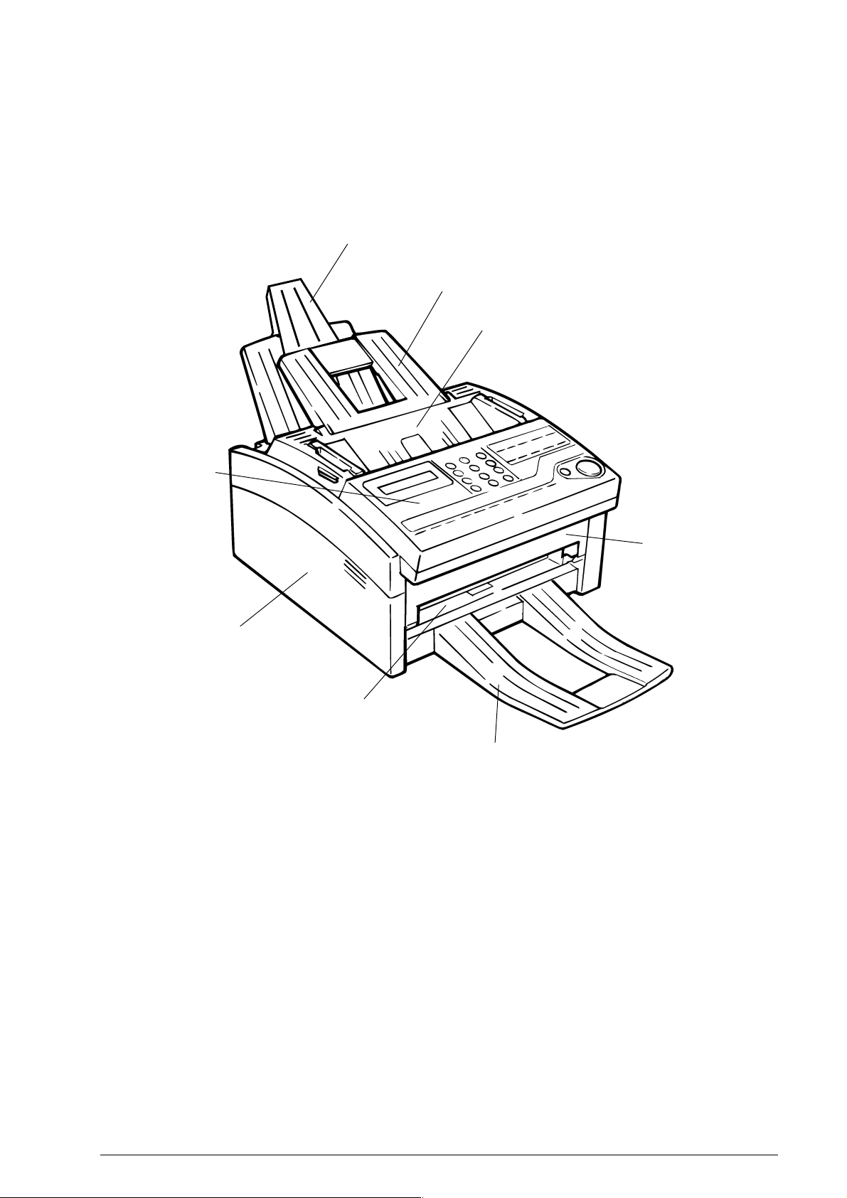
Figure 1.4.1 shows the general appearance of the OKIOFFICE44/OKIFAX 4100.
Figure 1.4.2 shows the general appearance of the OKIFAX 5000 series.
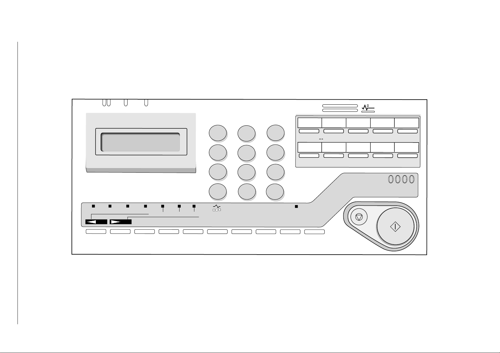
Figure 1.4.3 shows the control panel of the OKIOFFICE44/OKIFAX 4100.
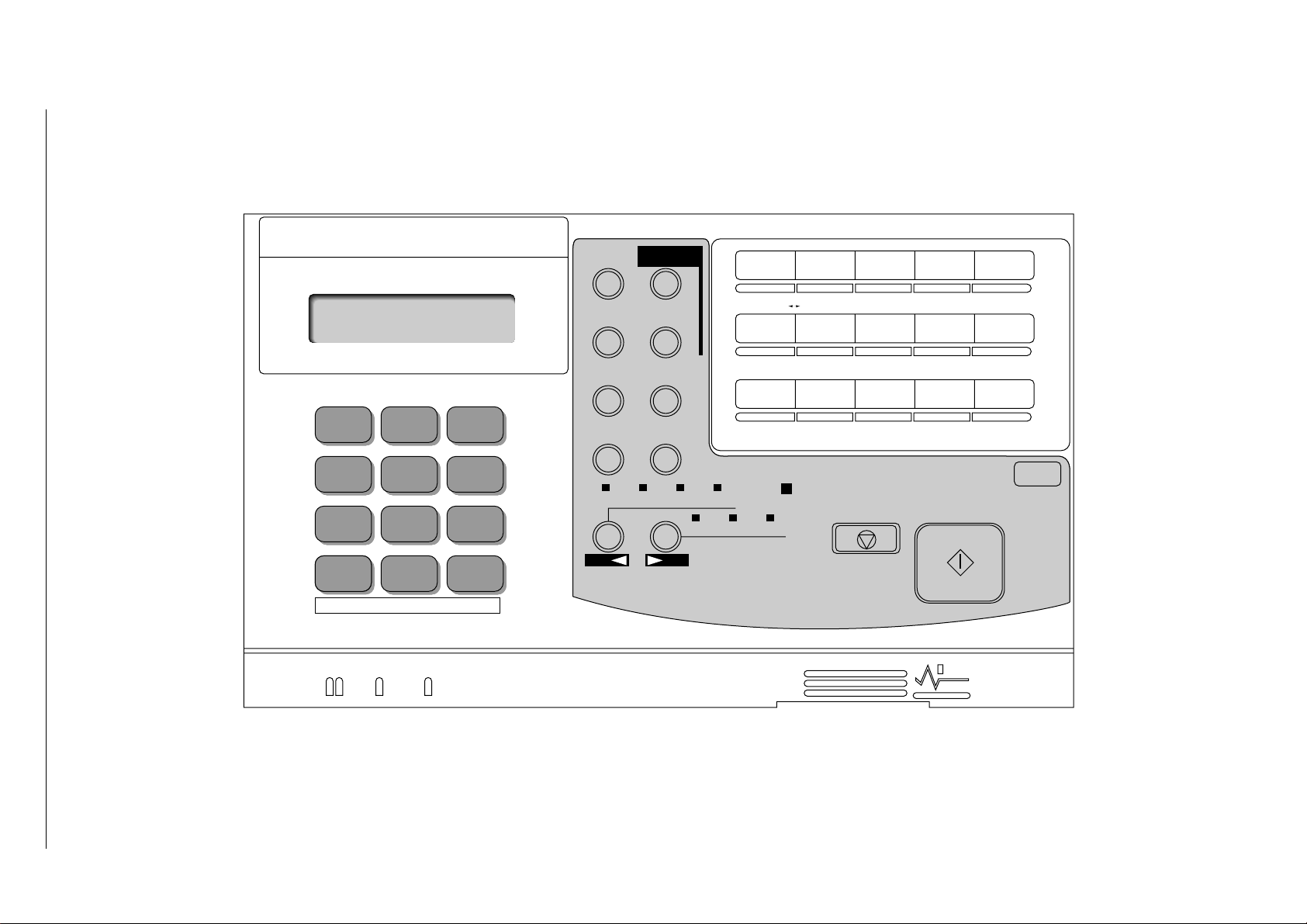
Figure 1.4.4 shows the control panel of the OKIFAX 5200/5300.
Figure 1.4.5 shows the control panel of the OKIFAX 5500/5600.
Case-OPE (T)
Tray-Paper
Tray-Document
Cover-Top
Cover-Main
Cover Manual Document
Stacker-Document (O
Figure 1.4.1 General Appearance of OKIOFFICE44/OKIFAX 4100
Cover-Front
tional)
(FX048 CP4.1 Fig. 01)
40055101TH Rev.4 13 /
Page 14
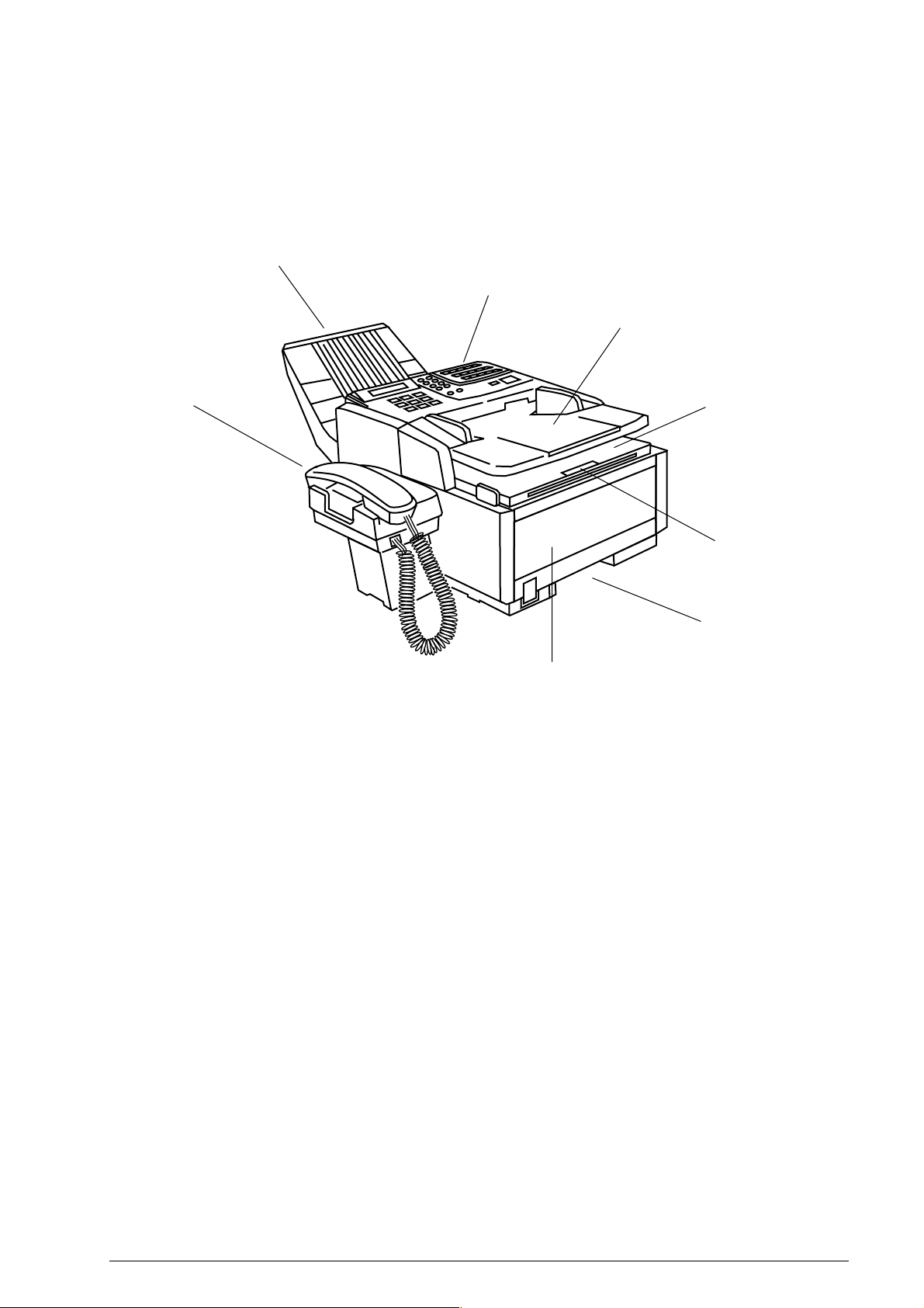
Document stacker
Control panel
Document tray
Telephone handset (option)
Copy stacker
Sub-paper tray
Recording paper cassette
Manual paper feeder cover
Figure 1.4.2 General Appearance of OKIFAX 5000 series
40055101TH Rev.4 14 /
Page 15
40055101TH Rev.4 15 /
8.5" A4 B5 A5
PHOTO
YES
EX FINE
FINE STD
NO
AUTO REC SEARCH
LIGHT
HYPHEN
NORMAL DARK
1
GHI
4
PQRS
7
*
HOOK
V.REQUEST
ABC DEF
2
JKL
5
TUV
8
0
UNIQUE
REDIAL
AUTO DIAL
3
MNO
6
WXYZ
9
#
ALARM
SELECT
FUNCTION
DELAYED
6
REPORT
PRINT
TX
COPY
BROADCAST
FEEDER TX
COUNTER
DISPLAY
321
CONF.TX
LOCATION
PROG.
OKIFAX
STOP
RELAY
INIT.-TX
9/PAUSE8/+7
USER
PROG.
54
POLLNG
10/PAUSE
MSG. PRINT
FROM MEMORY
OKI
START
Fiture 1.4.3 Control Panel of OKIFAX 4100
Page 16
40055101TH Rev.4 16 /
8.5" A4 B5 A4
ABC DEF
123
JKL MNOGHI
456
TUV
WXYZPQRS
789
*0#
TONE UNIQUE
AUTO REC
SERCH AUTO DIAL
HYPHEN REDIAL
COPY
PHOTO RX FINE FINE STD
YES
SELECT
FUNCTION
HOOK
V.REQUEST
LIGHT NORMAL DARK
NO
12 34 5
DELAYED
67 89 10
REPORT
PRINT
11 12 13/+
BROADCAST
TX
FEEDER TX
COUNTER
DISPLAY
CONF.TX
LOCATION
PROG.
RELAY
INIT.-TX
USER
PROG.
14/SPACE 15/PAUSE
POLLNG
MSG. PRINT
FROM MEMORY
OKI
ALARM
STOP START
OKIFAX
0000
Fiture 1.4.4 Control Panel of OKIFAX 5000 series
Page 17

1.5 Basic Performance Specifications
Table 1.5.1 shows basic performance specifications.
Note: TF: Technical function setting
FP: Function program setting
OT: One-touch key pressed
F: SELECT FUNCTION key pressed
Table 1.5.1 (1/10) Basic Performance Specifications
No. Item Specifications
1 Applicable line
2 Line interface
Rev.3
Rev.3
1) Impedance
2) Sending power level
3) Receiving power level
3 Type of document to be transmitted
1) Width
2) Length
1) General switched telephone network (GSTN)
2) Private branch exchange (PBX) (OT9+2)
600Ω balanced
0 dBm to –15 dBm range
(Adjustable in 1 dB steps. TF + 22)
–6 dBm to –46 dBm
Max. 216 mm (NA Letter)
Min. 148 mm (ISO A5 size)
Note: Effective reading width is NA Letter (215 mm).
Min. 128 mm
Max. 356 mm (14 inches)
Long document detection: 380 mm, or 60 minutes
* TF + 11 (To enable or disable the long document scanning)
3) Thickness
4) Shape
5) Opacity
Based on common bond paper,
a) 0.08 to 0.13 mm for multiple page feeding
b) 0.06 to 0.15 mm for single page feeding
Rectangular
Documents allowing less than 40% of the scanner source light to
pass through them.
40055101TH Rev.4 17 /
Page 18
Table 1.5.1 (2/10) Basic Performance Specifications
No. Item Specifications
4 Effective reading width
Rev.2
Document width
ISO A4 (210 mm)
Communication
Mode/Paper width
OKIOFFICE44/OKIFAX 4100
[INT'L/FTZ]
NA letter (216 mm)
OKIOFFICE44/OKIFAX 4100
[US/CANADA]
NA legal (216 mm)
OKIOFFICE44/OKIFAX 4100
[US/CANADA]
Note Local copy: Pritable reading width in local copy mode
5 Automatic document feeder (ADF)
Rev.3
Effective reading
G3/A4
208 mm for TX
200 mm for local copy
OKIFAX 5000 series
208 mm for TX
202.8 mm for local copy
G3/A4
215 mm for TX
200 mm for local copy
OKIFAX 5000 series
215.1 mm for TX
211.2 mm for local copy
G3/A4
215 mm for TX
200 mm for local copy
OKIFAX 5000 series
215.1 mm for TX
211.2 mm for local copy
Max. 20 documents for OKIOFFICE44/OKIFAX 4100: NA Letter or A4 (20-1b)
Max. 30 documents for OKIFAX 5000 series: NA Letter or A4
(20-1b)
Max. 15 documents: NA Letter or A4 (13-28lb bond paper)
Documents shall be placed facedown on ADF stacker.
The first sheet will be fed first in the feeder and will exit facedown
in the document stacker.
width
Copy size
A4
Letter
Legal
6 Document skew
Max. 2.6 mm skew over a document of A4 length.
For a document longer than A4 length, occurrence of skew
exceeding 2.6 mm over any A4 length is 0.5% or less.
7 Document jam detection
1) Transmission will stop and line disconnection will occur when
the end of a document is not detected within 356 mm after
scanning begins (except for the long document scanning. TF
+ 11)
2) A jam will also be declared if the document does not reach the
scanning position within 5.5 seconds (OKIFAX 5000 series)/
10 seconds (OKIOFFICE44/OKIFAX 4100) after the start of
a document feed.
Note: When a jam is detected during message transmission from
the feeder, the machine will stop scanning and disconnect
the line, but its receiving capability will remain valid.
8 Document jam removal
40055101TH Rev.4 18 /
Manual release
Page 19

Table 1.5.1 (3/10) Basic Performance Specifications
No. Item Specifications
9 Recording paper or sheet
For the first or second recording paper cassette:
1) Type: Plain paper cut (Bond paper)
2) Size: ISO A4 (210 mm x 297 mm)
NA Letter (215.9 mm x 279.4 mm)/(8.5 inch x 11
inch)
NA Legal (215.9 mm x 355.6 mm)/(8.5 inch x 14
inch)
3) Weight: 16 lbs to 24 lbs/base weight
Base weight is defined as the weight of 500 sheets
of 431.8 mm (17 inch) by 558.8 mm (22 inch).
4) Thickness:0.08 mm to 0.12 mm
5) Condition: New paper
For the manual loading feeder on the first cassette:
(OKIOFFICE44/OKIFAX 4100/5000 series)
1) Type: Plain paper, transparency for overhead projector,
colored paper, printed paper
2) Size: A4/NA Letter/NA Legal
10 Recording paper cassette
1) First tray
(For OKIOFFICE44/
OKIFAX 4100)
2) First cassette
(For OKIFAX 5000 series)
3) Second cassette (Option)
(For OKIFAX 5000 series)
3) Weight, thickness and condition: Same as above
Note: One single sheet only should be loaded on the manual
loading feeder for any one occasion.
For best results use Oki Data recommended papers
1) Xerox 4200 (20 - lb/base weight paper)
2) L-type paper for photo-printers
100 sheets/tray (Oki Data recommended paper)
250 sheets/cassette (Oki Data recommended paper)
500 sheets/cassette (Oki Data recommended paper)
40055101TH Rev.4 19 /
Page 20
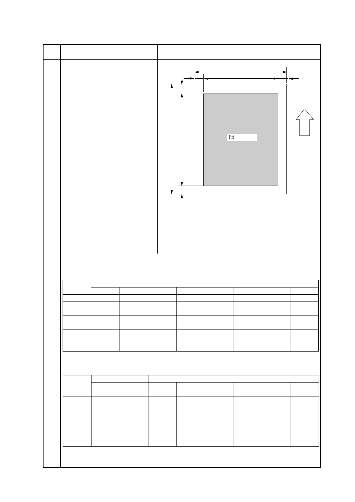
Table 1.5.1 (4/10) Basic Performance Specifications
Printing area
EL
PL
B
T
L
R
PW
EW
Recording
paper
feed
direction
(F050-C1-001)
No. Item Specifications
11 Effective recording area
Rev.2
Note: These tables do not
include vertical and horizontal addressing deviations (+
or –2 mm) of recording paper.
For OKIOFFICE44/OKIFAX 4100:
1) Printable area
NA LETTER SIZE ISO A4 SIZE 14 inch LEGAL SIZE
inch mm inch mm inch mm
PL 11 279.4 11.7 297 14 355.6
PW 8.5 216 8.27 210 8.5 216
EL 10.76 273.4 11.46 291 13.76 349.6
EW 8.0 203.2 8.0 203.2 8.0 203.2
T 0.12 3 0.12 3 0.12 3
B 0.12 3 0.12 3 0.12 3
L 0.25 6.35 0.13 3.4 0.25 6.35
R 0.25 6.35 0.13 3.4 0.25 6.35
NA LETTER SIZE ISO A4 SIZE 14 inch LEGAL SIZE
PL 11 279.4 11.7 297 14 355.6
PW 8.5 216 8.27 210 8.5 216
EL 10.5 266.7 11.2 284.3 13.5 342.9
EW 8.0 203.2 7.77 197.3 8.0 203.2
T 0.25 6.35 0.25 6.35 0.25 6.35
B 0.25 6.35 0.25 6.35 0.25 6.35
L 0.25 6.35 0.25 6.35 0.25 6.35
R 0.25 6.35 0.25 6.35 0.25 6.35
2) Guaranteed printing area
inch mm inch mm inch mm
13 inch LEGAL SIZE
inch
13
8.5
12.76
8.0
0.12
0.12
0.25
0.25
13 inch LEGAL SIZE
inch
13
8.5
12.5
8.0
0.25
0.25
0.25
0.25
mm
330.2
216
324.2
203.2
3
3
6.35
6.35
mm
330.2
216
317.5
203.2
6.35
6.35
6.35
6.35
40055101TH Rev.4 20 /
Page 21
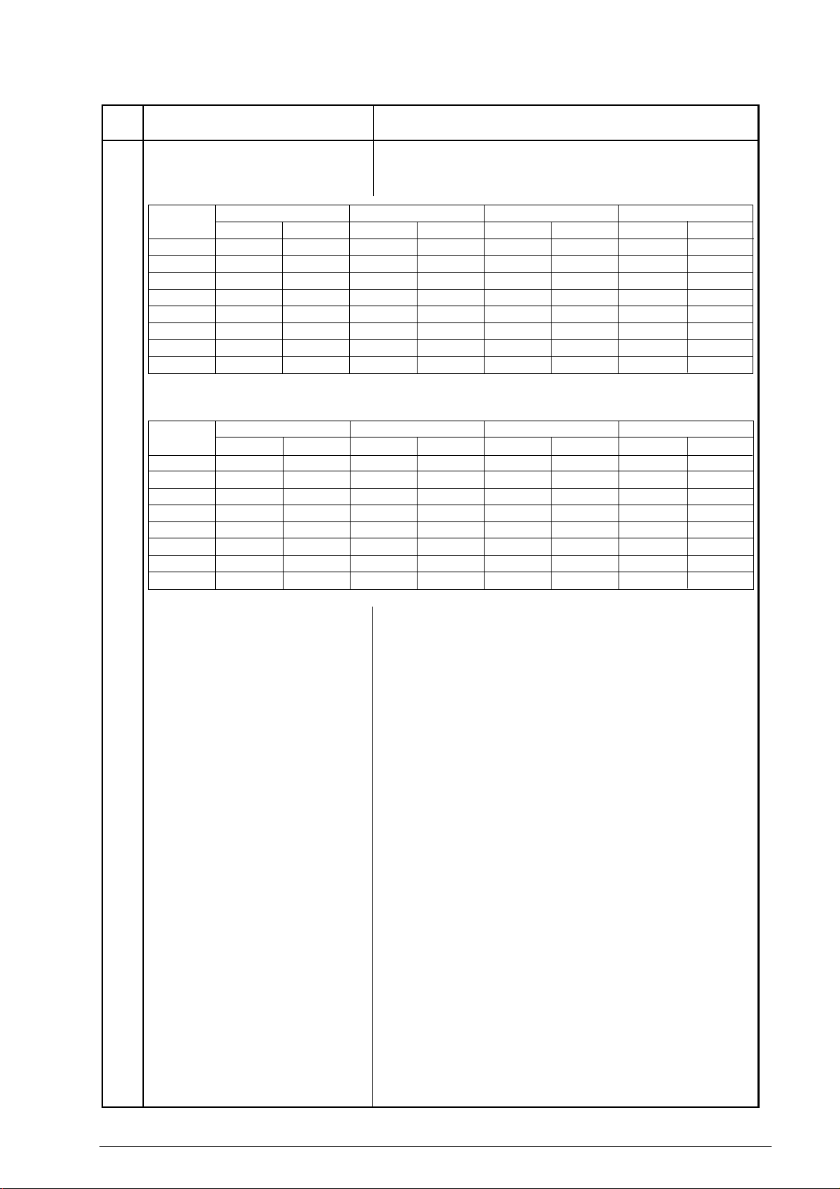
Table 1.5.1 (5/10) Basic Performance Specifications
No. Item Specifications
For OKIFAX 5000 series:
1) Printable area
NA LETTER SIZE ISO A4 SIZE 14 inch LEGAL SIZE
inch mm inch mm inch mm
PL 11 279.4 11.7 297 14 355.6
PW 8.5 216 8.27 210 8.5 216
EL 10.76 273.4 11.46 291 13.76 349.6
EW 8.32 211.3 8.11 206 8.32 211.3
T 0.12 3 0.12 3 0.12 3
B 0.12 3 0.12 3 0.12 3
L 0.09 2.3 0.08 2 0.09 2.3
R 0.09 2.3 0.08 2 0.09 2.3
2) Guaranteed printing area
NA LETTER SIZE ISO A4 SIZE 14 inch LEGAL SIZE
PL 11 279.4 11.7 297 14 355.6
PW 8.5 216 8.27 210 8.5 216
EL 10.5 266.7 11.2 284.3 13.5 342.9
EW 8.0 203.2 7.77 197.3 8.0 203.2
T 0.25 6.35 0.25 6.35 0.25 6.35
B 0.25 6.35 0.25 6.35 0.25 6.35
L 0.25 6.35 0.25 6.35 0.25 6.35
R 0.25 6.35 0.25 6.35 0.25 6.35
12 Copy stacking
inch mm inch mm inch mm
For OKIOFFICE44/OKIFAX 4100:
The fax can discharge printed copies and stack them faceup.
Maximum sheets on the copy stacker: 30*
13 inch LEGAL SIZE
inch
13
8.5
12.76
8.32
0.12
0.12
0.09
0.09
13 inch LEGAL SIZE
inch
13
8.5
12.5
8
0.25
0.25
0.25
0.25
mm
330.2
216
324.2
211.3
3
3
2.3
2.3
mm
330.2
216
317.5
203.2
6.35
6.35
6.35
6.35
13 Scanning resolution
Rev.2
For OKIFAX 5000 series:
The fax can discharge printed copies and stack them facedown.
Maximum sheets on the copy stacker: 100*
Note*:Oki Data recommended paper
Horizontal:
• 8 pel/mm for OKIOFFICE44/OKIFAX 4100 and OKIFAX
5200/5500 of INT’L version.
• 300 dot/inch for OKIFAX 5300/5600 of ODA version.
Vertical:
Transmission mode:
• 3.85 line/mm (STD), 7.7 line/mm (FINE) or 15.4 line/mm
(EX. FINE) for OKIFAX 4100 and OKIFAX 5200/5500 of
INT’L version.
• 3.85 line/mm (STD), 7.7 line/mm (FINE) or 300 dot/inch,(EX.
FINE) for OKIFAX 5300/5600 of ODA version.
COPY mode:
7.7 line/mm (FINE) or 15.4 line/mm (EX.FINE) for
OKIOFFICE44/OKIFAX 4100 and OKIFAX 5200/5500 of
INT’L version.
7.7 line/ mm(FINE) or 300 dot/inch(EX. FINE) for
OKIFAX5300/5600 of ODA version.
40055101TH Rev.4 21 /
Page 22

Table 1.5.1 (6/10) Basic Performance Specifications
No. Item Specifications
14 Image scanning method
Rev.2
15 Contrast control
16 Recording resolution
Rev.2
17 Recording system
18 Skew of recording paper
NA Letter size (1728-bit) contact image sensor for OKIOFFICE44,
OKIFAX4100/5200/5500
NA Letteer size (2592-bit) contact image sensor for OKIFAX 5300/
5600
1) Automatic background sensing
A continuous document background of 0.3 OD (optical density)
or less will be transmitted as white.
2) The LIGHT and DARK contrasts will automatically be adjusted
to improve image quality.
Horizontal:
• 300 dot/inch
Vertical:
• 3.85 line/mm (STD), 7.7 line/mm (FINE) for OKIOFFICE44/
OKIFAX 4100 and OKIFAX 5200/5500 of INT’L version.
• 3.85 line/mm (STD), 7.7 line/mm (FINE), 300 dot/inch (FXFINE) for OKIFAX 5300/5600 of ODA version.
Electro-photographic printing
1) 211.3mm (2496 bit) or 216.7mm (2560 bit) LED print head
Maximum allowable skew is + or - 1 mm over an advance of 100 mm.
19 Copy darkness
20 Copy uniformity
21 Recording paper running out
Rev.3
22 Minimum scan line time for receiving
23 Coding scheme
1) Black image: Greater than 1.0 OD (Optical density)
2) White background: Not greater than 0.2 OD
(Optical density)
Printed copies will exhibit a uniform density of the printed and
background area:
1) From edge to edge: 25% unit
2) From copy to the next copy: 30% unit
The fax can detect the no-paper condition by a photosensor.
When the paper has run out in the local copy operation, the scanning
will stop with “NO PAPER ... REPLACE PAPER” on the LCD for
OKIFAX 5000 series and “PAPER OUT/JAM” on the LCD for
OKIOFFICE44/OKIFAX4100 and an ALARM LED turns on without an alarm tone.
When the paper has run out while a message is being received and
the no-paper reception is activated, the LCD display will show
“MSG. IN MEMORY”, and the ALARM LED turns on.
0 ms, when receiving from an Oki Data facsimile.
5 ms at 7.7 line/mm and 10 ms at 3.85 line/mm when receiving from
a non-Oki Data facsimile.
1) One-dimensional coding scheme:
Modified Huffman (MH)
2) Two-dimensional coding scheme:
Modified READ (MR)
Modified modified READ (MMR)
40055101TH Rev.4 22 /
Page 23
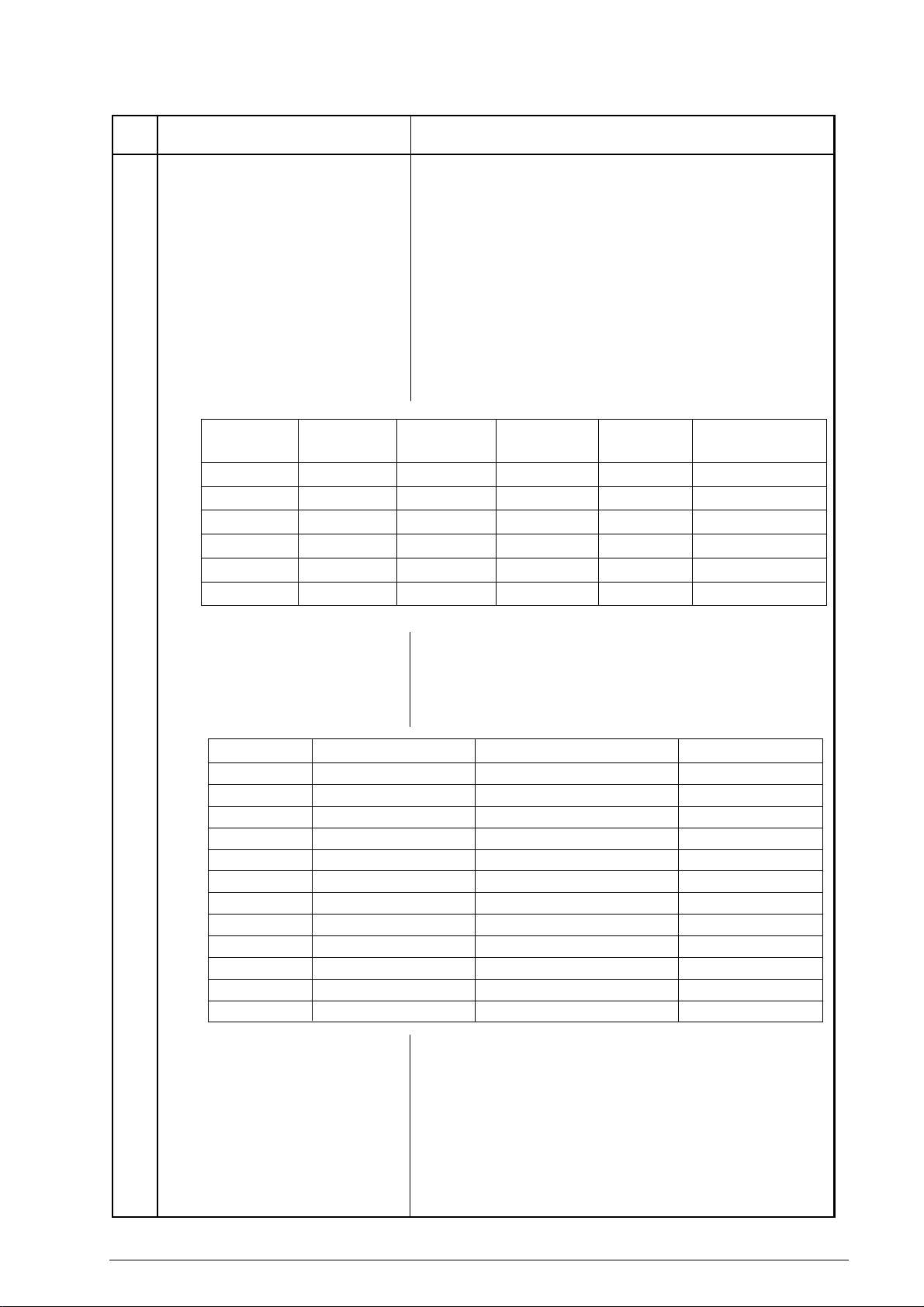
Table 1.5.1 (7/10) Basic Performance Specifications
No. Item Specifications
24 MODEM
Rev.2
1) High-speed MODEM
a) ITU-T Rec. V.29 (9600/7200 bps)
b) ITU-T Rec. V.27 ter (4800/2400 bps)
c) ITU-T Rec. V.17 (14400/12000/9600/7200 bps)
d) ITU-T Rec. V.33 (14400/12000 bps)
e) ITU-T Rec. V.34 (28800 bps); for OKIFAX 5500/5600
Note: 33600 bps (V.34) is available for OKIFAX 5500/5600
when serviceman set to enable.
2) Low-speed MODEM
25 Fallback
Rev.2
Fallback
rank
1st
2nd
3rd
4th
5th
6th
Fallback rank
1st
2nd
3rd
4th
5th
6th
7th
8th
9th
10th
11th
12th
Transmission
speed
14400 bps
12000 bps
9600 bps
7200 bps
4800 bps
2400 bps
Transmission speed
28800 bps
26400 bps
24000 bps
21600 bps
19200 bps
16800 bps
14400 bps
12000 bps
9600 bps
7200 bps
4800 bps
2400 bps
ITU-T Rec. V.21 channel 2 (300 bps)
Automatic fallback will occur according to the following sequence
by FTT, RTN or PPR.
Activated by
FTT (Times)
1
1
1
1
2
2
Activated by
RTN (Times)
1
1
1
1
1
1
Activated by
PPR (Times)
4 (Note 1)
4 (Note 1)
4 (Note 1)
4 (Note 1)
4 (Note 1)
4 (Note 1)
Protocol
ITU-T V.17 (V.33)
ITU-T V.17 (V.33)
ITU-T V.17 (V.29)
ITU-T V.17 (V.29)
ITU-T V.27 ter.
ITU-T V.27 ter.
When the last trial fails, the transmitting station sends out a DCN
signal to the remote station for disconnection.
Note 1: Continuous PPRs for the same partial page within each
fallback rank.
Activated byPPR (Times)
1 (Note 1)
1 (Note 1)
1 (Note 1)
1 (Note 1)
1 (Note 1)
1 (Note 1)
1 (Note 1)
1 (Note 1)
1 (Note 1)
1 (Note 1)
1 (Note 1)
1 (Note 1)
Protocol
ITU-T V.34
ITU-T V.34
ITU-T V.34
ITU-T V.34
ITU-T V.34
ITU-T V.34
ITU-T V.34
ITU-T V.34
ITU-T V.34
ITU-T V.34
ITU-T V.34
ITU-T V.34
Note 2: V.34 modern performs the fall-back depending upon the
line condition automatically.
26 Protocol
1) ITU-T Rec. T.30
2) Oki Data special protocol
High-speed protocol
The T.30 protocol signal from the transmitting station is sent at
message transmission speed instead of 300 bps.
Note: In high-speed protocol, 28.8 K-bps are not supported.
40055101TH Rev.4 23 /
Page 24
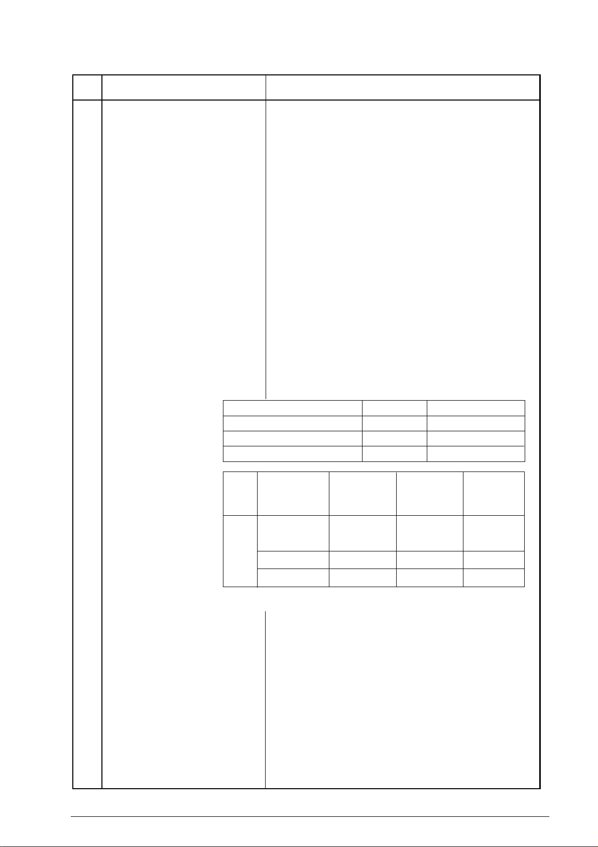
Table 1.5.1 (8/10) Basic Performance Specifications
No. Item Specifications
27 Transmission time
Rev.2
28 Error correction
29 Communication mode
30 Ringing signal detection sensitivity
1) Voltage range
2) Frequency range
3) Ring response time
31 Image memory
Rev.2
3 sec.(approx 3.5 sec) /ITU-T No. 1 sample document
(OKIFAX 5500/5600)
6 sec.(approx 6.9 sec) /ITU-T No. 1 sample document
(OKIOFFICE44, OKIFAX 4100/5000 series)
Note: This is Phase C time at 3.85 line/mm and 28800 bps for 3
sec. and 14400 bps for 6 sec. in MMR code transmission.
ITU-T Error correction mode (ECM)
Oki Data ITU-T ECM
Half-duplex
25 to 150 V r.m.s.
Inoperative below 10 V
20 to 68 Hz
One-ringing signal or 5 to 30 seconds.
(Selectable in 5 sec. steps. F + OT9 + ← + 11)
OKIOFFICE44/OKIFAX 4100
OKIFAX 5200/5300
OKIFAX 5500/5600
Basic model
256K-byte
256K-byte
512K-byte
Optional memory
1M-byte
1M-byte
1M-byte/2M-byte
32 Telephone handset
(option)
With
option
board
Memory
condition
Standard
(without option)
1M-byte
2M-byte
*1 CTR board is not mounted.
2
*
CTR board is mounted.
OKIFAX 4100
OKIOFFICE44
[pages]
20
100
OKIFAX
5200/5300
[pages]
20
100
OKIFAX
5500/5600
A4 Setting
[pages]
5500: 30*
5500: 26*
5600: 38
120
200
Note: ITU-T No.1 sample document is used to count the num-
ber of sheets.
Back-up time on electrical interruption:
Min. one hour (OKIFAX 5000 series with option memory)
Note: OKIOFFICE44/OKIFAX 4100 and OKIFAX 5000 se-
ries without option memory does not back up the message
received in memory for the power failure.
General telephone function is available while the power is on.
Note: In the fax special versions, general telephone is available
even when the power is off.
1
2
40055101TH Rev.4 24 /
Page 25
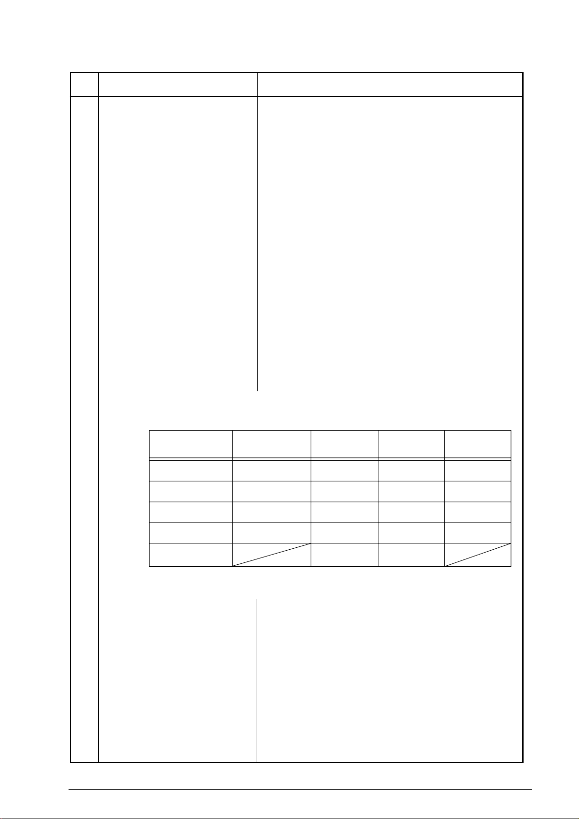
Table 1.5.1 (9/10) Basic Performance Specifications
No. Item Specifications
34 Overheat protection
35 PC interface applications (Option)
Rev.3
Note: This function is the standard
for OKI OFFICE44.
36 Power supply unit and power consump-
Rev.3
tion of the machine
The heater of the fuser unit is controlled within the predetermined
temperature range by the thermistor. If the temperature of the heater
exceeds the range, the LCD displays “PRINTER ALARM 4”.
Furthermore, the built-in thermostat in the fuser unit prevents the
heater from being overheated even in the event of the failures in the
above temperature control circuit.
The following four modes are supported:
1) PC local printer function
2) PC scanner function
3) PC FaxModem function
4) Location Programing function
Note: This function will be supplied as the OKIFAX 4100/5200/
5300/5500/5600 option in case Oki Data can get the
approval in respective countries without modifying the
optional unit.
For, details, see product specification for MFP.
Power consumption of the machine
(Typical power)
Transmit
Receive
Local copy
Standby
(Power Save OFF)
Standby
(Power Save ON)
37 Ambient condition
1) Operating condition
2) Storage condition
OKIFAX
5200/5500
60W
160W
210W
16.6W
0.5W
19W
115W
150W
10W
OKIFAX 4100OKIOFFICE44
21W
112W
150W
10W
0.5W
** OKIOFFICE44 has standard PC interface,
therfore has no power save mode.
OKIFAX5300/5600 has no power
save mode.
See Figure 1.5.1
See Figure 1.5.1
OKIFAX
5300/5600
60W
160W
210W
16.6W
40055101TH Rev.4 25 /
Page 26
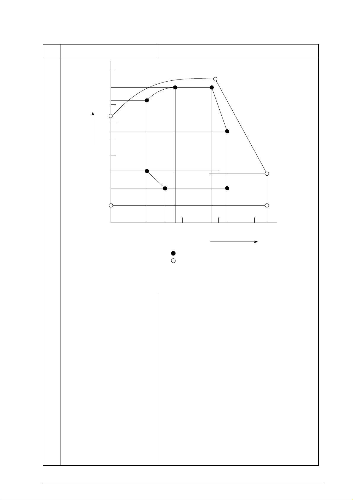
Table 1.5.1 (10/10) Basic Performance Specifications
No. Item Specifications
90
Temperature and Humidity Conditions
85%
80
73%
70
0°C64%
60
50
40
30
20
Relative humidity [%RH]
10
0°C10%
0
28°C85%
18°C80%
10°C73%
10°C30%
15°C20%
18°C
10 20 30 40
15°C
27°C80%
32°C54%
32°C20%
28°C
27°C
43°C29%
43°C10%
43°C
38 Dimension
Rev.2
(Main body)
39 Weight
(Main body)
40 Attachment
(to the main body)
TEMPERATURE [
Area enclosed by lines with : Range where printing is guaranteed.
Area enclosed by lines with : Range for storage without power supply.
(Note) The curve connecting 28°C, 85% and 0°C, 64%
is the condensation curve.
°C]
Figure 1.5.1 Ambient Conditions
For OKIOFFICE44/OKIFAX 4100:
1) Width: Approx. 312 mm
2) Depth: Approx. 383 mm
3) Height: Approx. 190 mm
OKIFAX 5000 series:
1) Width: Approx. 330 mm
2) Depth: Approx. 420 mm
3) Height: Approx. 245 mm
Approx. 8 kg for OKIOFFICE44/OKIFAX 4100
Approx. 13 kg for OKIFAX 5000 series
Excluding optional units, recording paper and packing materials.
1) AC power cord x 1
2) I/D unit x 1 (Already installed)
3) Toner cartridge x 1
4) Telephone handset x 1 (option)
5) Curled cord and Telephone cord for (4) x 1 (option)
6) Document stacker x 1
7) Line cord x 1
8) One touch sheet x 1 (Already installed)
9) User’s guide x 1
40055101TH Rev.4 26 /
Page 27

1.6 Reports and Lists
Table 1.6.1 shows Reports and Lists Specifications.
Note: F +OT: Press FUNCTION and One-touch key
FP: Function program setting
TF: Technical function setting
Table 1.6.1 (1/2) Reports and Lists Specifications
No. Item Specifications
1 Call-back message
2 Sender ID
3 Transmitting subscriber
identification(TSI) printing
4 Cancel report
(Power outage report)
5 Activity report
Rev.3
The transmitter sends a call-back message to the receiver only
when the receiver does not respond to voice request of the transmitter.
The fax can transmit a programmed alphanumeric message, such as
company’s name, consisting of up to 32 characters.
* (Outside only)
Received TSI can be printed at the top of the received page.
* TF + 05 (To enable or disable this function)
The fax can automatically print out a power-outage report when the
power off condition occurs.
The fax can print out an activity report manually, and provides a
record of your fax machine's last 30 communications. This report
does not contain the results of messages which were received
without errors. However it does contain messages received in
memory with or without errors.
* REPORT PRINTOUT+1(Manual printout)
6 Message confirmation report
7 Broadcast entry report
8 Broadcast confirmation report
40055101TH Rev.4 27 /
The fax can print out a message confirmation report manually or
automatically in the following cases.
(1) When COPY key is pressed after a single location
call, this report can be printed.
(Manual printout)
* FP + 01 (To enable or disable automatic printing)
The fax can print out a broadcast entry report if specified during
operating sequence of a broadcast.
The fax can print out a broadcast confirmation report manually or
automatically.
* COPY key (Manual printout): Pressed after a broadcast.
* REPORT PRINTOUT + 2 (Manual printout)
* FP +02 (To enable or disable automatic printing)
Page 28

Table 1.6.1 (2/2) Reports and Lists Specifications
No. Item Specifications
9 Confidential reception report
Rev.3
10 Telephone directory
11 Configuration report
OKIFAX 5000 series can print out this report automatically on
completion of a confidential reception.
This directory is printed manually.
(REPORT PRINTING +3)
This report is printed manually.
(REPORT PRINTING +4)
40055101TH Rev.4 28 /
Page 29

Call-back Message Format: (Example)
(1) (2)
07/01/96
(4)
(5)
(6)
(1) Date and time
(2) Sender ID
(3) CSI/Personal ID
(4) Letters "PLEASE CALL BACK"
(5) Sender ID
(6) Sender's call back telephone number
09:24 OKI SHIBAURA → OKI HONJO
PLEASE CALL BACK
OKI SHIBAURA
岼103 5476 1234
Sender ID Format: (Example)
(3)
NO.002
(F050-C1-002)
(1)
07/01/96 15:06 OKI ABC 1234 → 3454 2000 NO.021 01
(1)
Date and Time
(2)
Sender ID
(2) (3)
(4) (5)
~~
(3)
Receiver's CSI/Personal ID
(4)
Session number
(5)
Page number
(F050-C1-003)
40055101TH Rev.4 29 /
Page 30

TSI Printing and Local Date and Time Printing Format: (Example)
07/01/96 15:48 3454 1999
TSI printing
~~
Note: TSI printing (TF+05)
Local date and time printing
(F050-C1-004)
Local date and time printing (TF+04)
40055101TH Rev.4 30 /
Page 31

Cancel Report Format: (Example)
POWER OUT AGE REPORT
05/19/96 17:05
ID=OKI
DATE TIME S,R-TIME DISTANT STATION ID MODE PAGES RESULT
05/17 10:10 0485-88-3385 9080
05/17 10:30 ODS TAKASAKI 03 0000
05/17 12:05 01'20" OKI FAX BOX=01 03 OK 0000
05/17 13:00 00'20" 03-5476-4300 CALLED 01 OK 0000
05/17 15:40 034567092222 FWD-T 05
05/18 10:50 01'20" 0495-22-5400 CALLED 03 OK 0000
05/18 15:00 B.C. 01
Note: Memory reception only is printed on the mode in the report as called.
40055101TH Rev.4 31 /
Page 32

(1)
Activity Report Format: (Example)
ACTIVITY REPORT
(2)
05/19/96 17:05
(3)
ID=OKI
(4)
TOTAL TIME CALLING=08:22' CALLED=17:30'
DATE TIME S,R-TIME DISTANT STATION ID MODE PAGES RESULT
(5) (6) (7) (8) (9) (10) (11) (12)
05/17 10:00 01'20" OKI FAX CALLING 02 OK 0000
05/17 10:10 01'00" 0485 88 3385 CALLING 00 STOP 9080
05/17 10:30 00'20" ODS TAKASAKI CALLING 00 NO 90C1
05/17 12:05 01'20" OKI FAX CALLING 03 OK 0000
05/17 13:00 00'20" 03 5476 4300 CALLING 01 OK 0000
05/17 15:40 03'25" ODS TAKASAKI BOX=01 03 OK 0000
05/17 19:00 00'00" OKI FAX 01 OK 0000
05/18 10:10 02'00" OKI SHIBAURA CALLED 05 NO 908E
05/18 10:22 00'12" 0495 22 5400 CALLING 00 STOP 9080
05/18 10:50 01'20" 0495 22 5400 CALLED 03 NO 9090
05/18 12:05 00'20" OKI FAX CALLING 01 STOP 9080
05/18 15:00 01'30" CALLED 03 OK 0000
05/18 15:30 00'20" CALLING 01 OK 0000
05/18 17:05 05'20" B.C. COMP. 60A0
05/18 19:04 00'20" 03 5476 4300 CALLING 00 STOP 9080
05/19 09:00 01'11" CALLING 02 OK 0000
05/19 10:20 00'20" 03 5476 4300 CALLING 02 STOP 9080
05/19 10:35 02'23" BOX=01 02 OK 0000
05/19 10:50 00'20" ODS TAKASAKI CALLED 01 OK 0000
05/19 11:03 00'00" OKI FAX CALLING 00 STOP 9080
05/19 13:00 00'24" 03 5476 4300 01 OK 0000
05/19 16:00 03'25" ODS TAKASAKI FWD-R 03 OK 0000
05/19 16:04 03'30" OKIFAX FWD-T 03 OK 0000
*1
*2
*3
*4
*1
*5
*6
*7
*1 : Confidential reception
*2 : Manual TX
*3 : Memory reception
*4 : Broadcast TX
*5 : Manual memory reception
*6 : Reception for forwarding(OKIFAX 5500/5600)
*7 : Forwarding(OKIFAX 5500/5600)
40055101TH Rev.4 32 /
Page 33

(1) Title of the report
(2) Date and time when the report was printed
(3) Sender ID
(4) Total CALLING and CALLED time
(5) Date of transmission or reception
(6) Time when the communication started
(7) Time span of the fax communication.
(8) Identification of the remote station
Personal ID/Location ID/TSI/CSI/Dial number or space
(9) Communication mode:
(Rev.3)
CALLING (Transmission)
CALLED (Reception NG or MEMORY RX)
B. C. (Broadcast)
BOX=XX (Confidential reception for OKIFAX 5000 series)
FWD-R (Fax Fowarding RX)
FWD-T (Fax Fowarding TX)
POLLED (polling TX) in case of country code=GER, AUT, SUI
POLLING (polling RX) in case of country code=GER, AUT, SUI
(10) Number of transmitted pages or received pages
(11) Result code
OK (Note1)/NO/STOP (Note 2)/BUSY/PAPER (Out of recording paper)/S_JAM (Document
jam)/R_JAM (Recording paper jam)/COVER/COMP (Completion of a broadcast)/PUNIT
(Printer Alarm)/CANCL (Confidential reception T.O.)
Note 1: The following cases are included:
• Unmatched handshaking to the received NSF.
• Unmatched password to the received NSC in the polling transmission mode.
Note 2: The following cases are included:
• The STOP key is pressed.
• The memory cancellation operation removes the message from the active memory files.
(12) Service code
40055101TH Rev.4 33 /
Page 34

Message Confirmation Report Format (1/2): (Example)
MESSAGE CONFIRMATION
(1)
(2) 07/01/96 08:05
(3) ID=OKI
DATE S.R-TIME DISTANT STATION ID MODE PAGES RESULT
(5) (6) (7) (8) (9) (10)(4)
OKI FAX00'20"07/01 CALLING 02 OK 0000
(F050-C1-008 1/2)
40055101TH Rev.4 34 /
Page 35

Message Confirmation Report Format (2/2): (Example)
(1)
MESSAGE CONFIRMATION
(2) 07/01/96 17:05
(3) ID=OKI
DATE S.R-TIME DISTANT STATION ID MODE PAGES RESULT
(5) (6) (7) (8) (9) (10)(4)
OKI FAX00'20"07/01 B.C. 01 COMP 60A0
OKI OKIFAX17:0007/01/96 No.022 001
150 km
(11)
(F050-C1-008 2/2)
(1) Title of the report
(2) Date and time when the report was printed
(3) Sender ID
(4) Date of transmission or reception
(5) Length of time for which the fax was connected to the line
(6) Identification of the remote station
Personal ID/Location ID/TSI/CSI/Dial number
(7) Communication mode
Reference to ACTIVITY REPORT
(8) Number of transmitted pages or received pages
(9) Result of the communication
Reference to ACTIVITY REPORT
(10) Service code
(11) Message
40055101TH Rev.4 35 /
Page 36

Broadcast Entry Report Format: (Example)
BROADCAST ENTRY REPORT
07/01/96 17:05
ID=OKI
LOCATION ID LOCATION ID LOCATION ID
ONE TOUCH
1 = OT1 2 = OT2 3 = OT3
4 = OT4 5 = OT5 6 = OT6
7 = OT7 8 = OT8 9 = OT9
10 = OT10 *1 11 = OT11 12 = OT12
13 = OT13 14 = OT14 15 = OT15 *2
16 = OT16 17 = OT17 18 = OT18
19 = OT19 20 = OT20 21 = OT21
22 = OT22 23 = OT23 24 = OT24
25 = OT25 26 = OT26 27 = OT27
28 = OT28 29 = OT29 30 = OT30 *3
AUTO DIAL
01 = AD1 02 = AD2 03 = AD3
04 = AD4 05 = AD5 06 = AD6
07 = AD7 08 = AD8 09 = AD9
10 = AD10 11 = AD11 12 = AD12
13 = AD13 14 = AD14 15 = AD15
16 = AD16 17 = AD17 18 = AD18
19 = AD19 20 = AD20 21 = AD21
22 = AD22 23 = AD23 24 = AD24
25 = AD25 26 = AD26 27 = AD27
28 = AD28 29 = AD29 30 = AD30
31 = 31 32 = 32 33 = 33
34 = 34 35 = 35 36 = 36
37 = 37 38 = 38 39 = 39
40 = 40 41 = 41 42 = 42
43 = 43 44 = 44 45 = 45 *1
46 = 46 47 = 47 48 = 48
49 = 49 50 = 50 51 = 51
52 = 52 53 = 53 54 = 54
55 = 55 56 = 56 57 = 57
58 = 58 59 = 59 60 = 60
61 = 61 62 = 62 63 = 63
64 = 64 *2 65 = 65 66 = 66
67 = 67 68 = 68 69 = 69
70 = 70 71 = 71 72 = 72
73 = 73 74 = 74 75 = 75
76 = 76 77 = 77 78 = 78
79 = 79 80 = 80 81 = 81
82 = 82 83 = 83 84 = 84
85 = 85 86 = 86 87 = 87
88 = 88 89 = 89 90 = 90
91 = 91 92 = 92 93 = 93
94 = 94 95 = 95 96 = 96
97 = 97 98 = 98 99 = 99 *3
KEYPAD
1234
2345
3456
4567
*1 OKIOFFICE44/OKIFAX4100 : 10 45 1
*2 OKIFAX5200/5300 :15 64 5
*3 OKIFAX5500/5600 :30 99 5
MAX.
OT AD KEYPAD
40055101TH Rev.4 36 /
Page 37

Broadcast Confirmation Report Format: (Example)
BROADCAST CONFIRMATION REPORT
PAGES = 01
TOTAL TIME = 00:02'30"
07/01/96 17:05
ID=OKI
ONE TOUCH
1 = OT1
3 = OT3
5 = OT5
LOCATION ID PAGES RESULT
*1
*1
*1
01
01
01
OK
OK
OK
LOCATION ID PAGES RESULT
2 = OT2
4 = OT4
*1
*1
AUTO DIL
KEYPAD
01 = AD1
03 = AD3
05 = AD5
1234
3456
5678
*1
*1
*1
*1
*1
*1
01
01
01
01
01
01
OK
OK
OK
OK
OK
OK
02 = AD2
04 = GERMAN
*1
*1
*1: Identification of remote station
Personal ID, TSI, Location ID or Dial number
(Printing in this order depending if information is programed in remote fax machine)
Confidential Reception Report Format: (Example)
0101OK
OK
0101OK
OK
(F030-C1-010)
CONFIDENTIAL RX REPORT
07/01/96 17:05
ID=OKI
DATE TIME S,R-TIME DISTANT STATION ID MODE PAGES RESULT
07/01 00:20 00'00" OKI FAX
*2: Identification of remote station
Personal ID or CSI
*2
BOX=01 02 OK 0000
40055101TH Rev.4 37 /
Page 38

Telephone Directory for OKIOFFICE44/OKIFAX 4100 (1/2): (Example)
TELEPHONE DIRECTORY P1
07/01/96 19:19
ID=OKI DATA CORP.
ONE TOUCH
AUTO DIAL
LOCATION ID TEL NO. PRM. ECHO
1 OKI SERVICE
2 OKI OFFICE 456 456 456 (OFF)
3 OKI LABORATORY 789 789 789 (OFF)
4 ODC TAKASAKI 000 111 222 (OFF)
5 ODC QA/QC LAB. 1234 5678 90123 (OFF)
6 (OFF)
7 (OFF)
8 (OFF)
9 (OFF)
10 (OFF)
01
02
03
04
05
06
07 ODC TAKASAKI 0273 28 1234
08
09
10
11
12
13
14
15
16
17
18
19
20
21
22
23
24
25
26
27
28
29
30
31
32
33
34
35
36
37
38
39
40
41
42
43
44
45
123 123 123 (OFF)
OR 111 222 333
OR 444 555 666
OR 777 888 999
OR 444 555 666
OR 123 123 123
OR
OR
OR
OR
OR
40055101TH Rev.4 38 /
Page 39

Telephone Directory for OKIOFFICE44/OKIFAX 4100 (2/2): (Example)
TELEPHONE DIRECTORY P2
GROUP NUMBER = #1 #2 #3 #4 #5
#1 ONE TOUCH
1 2 3 4 5 6 7 8 9 10
AUTO DIAL
01 02 03 04 05 06 07 08 09 10 11 12 13 14 15 16 17 18 19 20 21 22 23 24 25
26 27 28 29 30 31 32 33
#2 ONE TOUCH
AUTO DIAL
#3 ONE TOUCH
07/01/96 19:20
ID=OKI DATA CORP.
AUTO DIAL
#4 ONE TOUCH
AUTO DIAL
#5 ONE TOUCH
5
AUTO DIAL
07
40055101TH Rev.4 39 /
Page 40

Telephone Directory for OKIFAX 5200/5300 (1/4): (Example)
TELEPHONE DIRECTORY P1
07/01/96 18:31
ID=OKI
ONE TOUCH
LOCATION ID TEL NO. PRM. ECHO
1 OKI SERVICE
2 (OFF)
3 (OFF)
4 (OFF)
5 (OFF)
6 (OFF)
7 (OFF)
8 (OFF)
9 (OFF)
10 (OFF)
11 (OFF)
12 (OFF)
13 (OFF)
14 (OFF)
15 (OFF)
123 123 456 (OFF)
OR 111 222 333
OR
OR
OR
OR
OR
OR
OR
OR
OR
OR
OR
OR
OR
OR
40055101TH Rev.4 40 /
Page 41

Telephone Directory for OKIFAX 5200/5300 (2/4): (Example)
TELEPHONE DIRECTORY P2
07/01/96 18:31
ID=OKI
AUTO DIAL
01 ODC TAKASAKI
02
03
04
05
06
07
08
09
10
11
12
13
14
15
16
17
18
19
20
21
22
23
24
25
26
27
28
29
30
31
32
34
35
36
37
38
39
40
41
42
43
44
45
46
47
48
49
50
51
52
53
54
55
56
57
58
59
60
61
62
63
64
LOCATION ID
TEL NO.
1234 56 7890
1234 56 7780
(F050-C1-017)
40055101TH Rev.4 41 /
Page 42

Telephone Directory for OKIFAX 5200/5300 (3/4): (Example)
TELEPHONE DIRECTORY P3
GROUP NUMBER = #1 #2 #3 #4 #5 #6 #7
#1 ONE TOUCH
1 2 3 4 5 6 7 8 9 10 11 12 13 14 15
AUTO DIAL
01 02 03 04 05 06 07 08 09 10 11 12 13 14 15 16 17 18 19 20 21 22 23 24 25
26 27 28 29 30
#2 ONE TOUCH
1 5 10 15
AUTO DIAL
07 30 40
#3 ONE TOUCH
07/01/96 18:32
ID=OKI
AUTO DIAL
#4 ONE TOUCH
AUTO DIAL
#5 ONE TOUCH
AUTO DIAL
#6 ONE TOUCH
AUTO DIAL
#7 ONE TOUCH
AUTO DIAL
40055101TH Rev.4 42 /
Page 43

Telephone Directory for OKIFAX 5200/5300 (4/4): (Example)
TELEPHONE DIRECTORY P4
GROUP NUMBER = #8 #9 #10
#8 ONE TOUCH
AUTO DIAL
#9 ONE TOUCH
AUTO DIAL
#10 ONE TOUCH
07/01/96 18:32
ID=OKI
AUTO DIAL
(F050-C1-019)
40055101TH Rev.4 43 /
Page 44

Telephone Directory for OKIFAX 5500/5600 (1/6): (Example)
TELEPHONE DIRECTORY P1
07/01/96 17:05
ID=OKI
ONE TOUCH
LOCATION ID TEL NO. PRM. ECHO
1 OKI SERVICE
2 ODC 0002 (OFF)
3NEW YORK 0003 (OFF)
4 OT4 ABC 0004 (OFF)
5 XYZ CO. 0005 (OFF)
6UK PLANT 0006 222 (OFF)
7 GERMANY 0007 (OFF)
8BT 0008 (OFF)
9 FRANCE 0009 (OFF)
10 TOKYO 0010 (OFF)
11 (OFF)
12 (OFF)
13 (OFF)
14 (OFF)
15 (OFF)
16 (OFF)
17 (OFF)
18 (OFF)
19 (OFF)
20 (OFF)
21 (OFF)
22 (OFF)
23 (OFF)
24 (OFF)
25 (OFF)
26 (OFF)
27 (OFF)
28 (OFF)
29 (OFF)
30 (OFF)
0001 123 345 (ON)
OR 0101 123 567
OR 0102
OR 0103
OR 0104
OR 0105 111
OR 0106
OR 0107
OR 0108
OR 0109
OR 0011
OR
OR
OR
OR
OR
OR
OR
OR
OR
OR
OR
OR
OR
OR
OR
OR
OR
OR
OR
OR
40055101TH Rev.4 44 /
Page 45

Telephone Directory for OKIFAX 5500/5600 (2/6): (Example)
TELEPHONE DIRECTORY P2
07/01/96 17:05
ID=OKI
AUTO DIAL
LOCATION ID TEL NO.
01 TOKYO OFFICE
02 PARIS 1002 111 333
03 AMERICA 1003
0 4 TOKYO 3 1004
0 5 TOKYO 5 1005
06 UK 1006
07 BT 1007
08 FRANCE 1008
09 GERMANY 1009
10 ITALY 1010
11 SPAIN 1011 567 890
12 DENMARK 1012 571 123
13 FINLAND 1013
14 SWITLAND 1014
15 OSAKA 1015 456 6789
16 TAKASAKI 1016
17 HONJO 1017
18 SHIBAURA 1018
19
20
21
22
23
24
25
26
27
28
29
30
31
32
33
34
35
36
37
38
39
40
41
42
43
44
45
46
47
48
49
50
51
52
53
54
55
56
57
58
59
60
61
62
63
64
1001 111 222
40055101TH Rev.4 45 /
Page 46

Telephone Directory for OKIFAX 5500/5600 (3/6): (Example)
TELEPHONE DIRECTORY P3
07/01/96 17:05
ID=OKI
AUTO DIAL
LOCATION ID TEL NO.
65
66
67
68
69
70
71
72
73
74
75
76
77
78
79
80
81
82
83
84
85
86
87
88
89
90
91
92
93
94
95
96
97
98
99 OKIDATA 234 5678
40055101TH Rev.4 46 /
Page 47

Telephone Directory for OKIFAX 5500/5600 (4/6): (Example)
TELEPHONE DIRECTORY P4
07/01/96 17:05
ID=OKI
GROUP NUMBER = #1 #2 #3 #4 #5 #6 #7
#1 ONE TOUCH
1 2 3 4 5 6 7 8 9 10 11 12 13 14 15 16 17 18 19 20 21 22 23 24 25
26 27 28 29 30
AUTO DIAL
01 02 03 04 05 06 07 08 09 10 11 12 13 14 15 16 17 18 19 20 21 22 23 24 25
26 27 28 29 30 31 32 33 34 35 36 37 38 39 40 41 42 43 44 45 46 47 48 49 50
51 52 53 54 55 56 57 58 59 60 61 62 63 64 65 66 67 68 69 70 71 72 73 74 75
76 77 78 79 80 81 82 83 84 85 86 87 88 89 90 91 92 93 94 95 96 97 98 99
#2 ONE TOUCH
AUTO DIAL
#3 ONE TOUCH
AUTO DIAL
#4 ONE TOUCH
AUTO DIAL
#5 ONE TOUCH
AUTO DIAL
#6 ONE TOUCH
AUTO DIAL
#7 ONE TOUCH
AUTO DIAL
40055101TH Rev.4 47 /
Page 48

Telephone Directory for OKIFAX 5500/5600 (5/6): (Example)
TELEPHONE DIRECTORY P5
GROUP NUMBER = #8 #9 #10 #11 #12 #13 #14
#8 ONE TOUCH
AUTO DIAL
#9 ONE TOUCH
AUTO DIAL
07/01/96 17:05
ID=OKI
#10 ONE TOUCH
AUTO DIAL
#11 ONE TOUCH
AUTO DIAL
#12 ONE TOUCH
AUTO DIAL
#13 ONE TOUCH
AUTO DIAL
#14 ONE TOUCH
AUTO DIAL
40055101TH Rev.4 48 /
Page 49

Telephone Directory for OKIFAX 5500/5600 (6/6): (Example)
TELEPHONE DIRECTORY P6
GROUP NUMBER = #15 #16 #17 #18 #19 #20
#15 ONE TOUCH
AUTO DIAL
#16 ONE TOUCH
AUTO DIAL
07/01/96 17:05
ID=OKI
#17 ONE TOUCH
AUTO DIAL
#18 ONE TOUCH
AUTO DIAL
#19 ONE TOUCH
AUTO DIAL
#20 ONE TOUCH
AUTO DIAL
40055101TH Rev.4 49 /
Page 50

Configuration Report (User)
CONFIGURATION
07/01/96 17:05
ID=OKI
FUNCTION LIST
01:MCF (SINGLE-LOC.) 02:MCF (MULTI-LOC.) 03:ERR.REPORT (MCF)
ON ON ON
04:MESSAGE IN MCF 05:SENDER ID. 06:MONITOR VOLUME
ON ON LOW
07:BUZZER VOLUME 08:CLOSED NETWORK 09:TX MODE DEFAULT
MIDDLE OFF FINE/NORMAL
10:T/F TIMER PRG. 11:RING RESPONSE *3 12:DISTINCTIVE RING *3
35SEC 1RING OFF
13:1'ST PAPER SIZE 14:2'ND PAPER SIZE *1 15:USER LANGUAGE
A4 A4 ENGLISH
16:INCOMING RING 17:REMOTE RECEIVE 18:MEM./FEEDER SWITCH
ON OFF MEMORY
19:POWER SAVE MODE *4 20:ECM FUNCTION 21:REMOTE DIAGNOSIS
ON ON OFF
22:PC/FAX SWITCH *2
ON
TEL NO. = 12345678901234567890
CALL BACK NO. = 12345678901234567890
FORWARD TEL NO. = 12345678901234567890
REDIAL TRIES 3TRY *3 REDIAL INTERVAL 3MIN *3
DIAL TONE DETECT OFF *3 BUSY TONE DETECT ON *3
MF(TONE)/DP(PULSE) MF *3 PULSE DIAL RATE 10PPS *3
PULSE MAKE RATIO 39% *3 PULSE DIAL TYPE NORMAL *3
MF (TONE) DURATION 100MSEC *3 PBX LINE OFF *3
PBX TYPE NORMAL *3 AUTO START ON *3
DIAL PREFIX OFF *3 IT2 DETECT ON *3
*1 Function 14 is printed when 2'nd Tray is installed.
*2 Function No.22 is printed when CTR board is installed.
*3 Depending on local PTT requirements, certain user function
and dial parameters are not printed and can not be sellected by the user.
*4 Function 19 is only for OKIFAX4100/5200/5500(See page 1-20, No.35 and 36)
40055101TH Rev.4 50 /
Page 51

Service Default Report (Configuration Report: Service bit=ON)
CONFIGURATION
07/01/96 17:05
ID=OKI
FUNCTION LIST
01:SERVICE BIT 02:MONITOR CONT. 03:COUNTRY CODE
ON OFF USA
04:TIME/DATE PRINT 05:TSI PRINT 06:NO TONER MEM. RX
OFF OFF ON
07:TAD MODE 08:REAL TIME DIAL 09:TEL/FAX SWITCH
TYPE2 TYPE2 ON
10:MDY/DMY. 11:LONG DOC. SCAN 12:TONE FOR ECHO
MDY OFF OFF
13:MH ONLY 14:H/MODEM RATE 15:T1 (TX) TIMER VALUE
OFF 14.4K 059
16:T1 (RX) TIMER VALUE 17:T2 TIMER VALUE 18:DIS BIT32
035 100 ON
19:ERR. CRITERION VALUE 20:OFF HOOK BYPASS 21:NL EQUALIZER
10 OFF 0DB
22:ATTENUATOR 23:T/F TONE ATT. 24:MF ATT.
10DB 10DB 6DB
25:RING DURA. * 10MS 26:CML TIMING * 100MS 27:LED HEAD STROBE
12 3 10100
28:LED HEAD WIDTH 29:MEDIA TYPE 30:TR LATCH CURRENT
TYPE1 MEDIUM +1
31:SYMBOL RATE
3200
Note: No. 30 is only for OKIOFFICE44/OKIFAX4100.
No. 31 is only for OKIFAX5500/OKIFAX5600.
40055101TH Rev.4 51 /
Page 52

2. INSTALLATION PROCEDURE A. Setup Information
2.1 General
The following flowchart outlines the installation procedure.
Site selection
Unpacking
Check of contents
Installation of attachments
AC cord connection
Telephone and line connections
Packing for shipment
(See 2.2)
(See 2.3)
(See 2.4)
(See 2.5)
(See 2.6)
(See 2.7)
(See 2.8)
General procedure key operations
Technical functions
Technical functions example
User's functions
User's functions example
Clock adjustment
1
(See 2.9.1)
(See 2.9.2)
(See 2.9.3)
(See 2.9.4)
(See 2.9.5)
(See 2.9.6)
• Function Program
• Ring response time
• Dial parameter
(service bit off)
40055101TH Rev.4 52 /
Page 53

1
Dual access operations
System data programming
*
One-touch key programming
*
Two-digit auto dial programming
*
Group setting
Dial parameter settings
*
Programming mail box password
(See 2.9.7)
(See 2.9.8)
TSI/sender ID included.
(See 2.9.9)
*
Memory operations
Off-line tests
On-line tests
Installation of optional units
* : See user's guide
(See 2.9.10)
(See 2.9.11)
(See C)
• Memory PC Board
• Second cassette cabinet
• PC interface
40055101TH Rev.4 53 /
Page 54

2.2 Site Selection
INSTALLATION
Precautions for Installation
(1) Fluctuation in line voltage
• 120VAC (102V to 127V)
• 230VAC (198V to 264V)
(2) Room temperature
50 to 90°F (10 to 32°C)
(3) Humidity
20 to 80% RH
(4) Operating environment
Pressure: Equivalent to altitude of 2500 m and below.
(5) Exposure
Within five minutes at luminous intensity 2,000 lux (with the stacker cover opened).
As an example, OKIFAX 5200/5300 is shown below:
(6) Required space for installation
The facsimile requires the space as shown below for safety and good operability.
Telephone Handset
(option)
11.81"
(300mm)
1
11.81"
(300mm)
FX-050VP-C2-001
40055101TH Rev.4 54 /
Page 55

(196mm)
(46mm)
243
11.81"
(300mm)
3
240
In case of scanning length
(Max. 14 inches: 356mm)
19.69"
(500mm)
Note: 1 This space is necessary for handling the handset. (option) (page 2-3)
2 This space is necessary for removing the recording paper cassette.
3 This space is necessary for installing the document stacker and to allow space for the fan
exhaust.
(7) Levelness of installation surface
1 degree max.
2
FX-050VP-C2-002
(8) Other requirements
Avoid installing in any of the following places:
• A place exposed to direct sunlight
• A place near a heat source or exposed to vibration
• A dusty place
• A place in the atmosphere of acid gas, or steam etc.,
• A place exposed to quick temperature changes
40055101TH Rev.4 55 /
Page 56

2.3 Unpacking
2.3.1 Unpacking for OKIOFFICE44/OKIFAX 4100
Procedure
(1) Remove tape on the top of the carton box and open its cover.
External carton box
Packing tape
Carton label
Packing tape
Figure 2.3.1.1 Unpacking Procedure (1)
(2) Take out the accessory box from the carton box.
(See Figure 2.3.1.1)
(3) Take out the machine with plastic wrapper from the box.
FX048-C2-003
40055101TH Rev.4 56 /
Page 57

T
ray-documen
t
Toner cartrige
onnectiong cords
ed cellophane tape
(4 points)
d-Side (L)
0240201)
Tray-paper
Carton box sheet
(40240101)
Machine
-
External carton box
FX048-C2-004
Figure 2.3.1.1 Unpacking Procedure (2)
40055101TH Rev.4 57 /
Page 58

2.3.2 Unpacking for OKIFAX 5000 Series
Procedure
(1) Remove tape on the top of the carton box and open its cover.
External carton box
Packing tape
Carton label
Packing tape
FX050-C2-003
Figure 2.3.2.1 Unpacking Procedure (1)
(2) Take out the accessory box from the carton box.
(See Figure 2.3.2.1)
(3) Take out the machine with plastic wrapper from the box.
40055101TH Rev.4 58 /
Page 59

Left cushion assembly
(Top)
Accessories box
Right cushion assembly
(Top)
Left cushion assembly
(Bottom)
Fixed tape
Machine
Front
Right cushion assembly
(Bottom)
Polyethylene film
External carton box
FX050-C2-004
Figure 2.3.2.1 Unpacking Procedure (2)
40055101TH Rev.4 59 /
Page 60

Cushion
AC power cord
Polyethlene bag
Top carton box
Cellophane tape
Modular cord
Polyethylene bag
Document stacker
Carton frame
Separation frame
Toner cartridge
(In damp proof bag)
Accessories box
Packing tape
Accessories box
FX050-C2-005
Figure 2.3.2.2 Unpacking Procedure (3)
40055101TH Rev.4 60 /
Page 61

2.4 Check of Contents
After having taken out the machine and accompanied accessories from the carton box, check the contents
according to the following list:
Table 2.4.1 Contents List for OKIOFFICE 44/OKIFAX 4100
Item No. Name Q'ty Remarks
1 OKIOFFICE44/ 1
OKIFAX4100 facsimile
2 AC power cord 1
3 I/D unit 1 Already installed.
4 Toner cartridge 1
5 Line cord 1
6 One touch sheet 1 Already installed.
7 User's guide 1 vol.
8 Tray paper 1
9 Tray document 1
Table 2.4.2 Contents List for OKIFAX 5000 Series
Item No. Name Q'ty Remarks
1 OKIFAX 5000 series 1
facsimile
2 AC power cord 1
3 I/D unit 1 Already installed.
4 Toner cartridge 1
5 Document stacker 1
6 Line cord 1
7 One touch sheet 1 Already installed.
8 User's guide 1 vol.
40055101TH Rev.4 61 /
Page 62

2.5 Installation of Attachments
2.5.1 Installation of Attachments for OKIOFFICE44/OKIFAX 4100
(1) Items
• Image Drum (ID) Unit (already installed)
• Toner cartridge
• Recording paper
• Tray-paper, Tray-document and Document-stacker
(2) Procedure
1) Toner cartridge
• Peel off the fixed tape attached to the cover-top.
• Open the cover-top.
Cover-Top
Figure 2.5.1.1 Toner Cartridge Installation (1)
• Take the plastic cover out of the ID unit.
FX048-C2-006
Mold cover
FX048-C2-007
Figure 2.5.1.2 Toner Cartridge Installation (2)
40055101TH Rev.4 62 /
Page 63

• Take out the toner cartridge from the damp proof bag, shake it five or six times as shown in the
illustration to eliminate the toner deflection, and peel off the seal gently.
Seal
Toner cartridge
FX048-C2-008
Figure 2.5.1.3 Toner Cartridge Installation (3)
• Ensure that the plastic tab on the right-hand side of the toner cartridge recess lines up with the
groove on the toner cartridge.
• Press down on both ends to make sure the cartridge is fully seated.
Toner cartrige
Figure 2.5.1.4 Toner Cartridge Installation (4)
FX048-C2-009
40055101TH Rev.4 63 /
Page 64

• Push the gray tab forward until it stops.
Toner cartrige
Gray tab
FX048-C2-010
Figure 2.5.1.5 Toner Cartridge Installation (5)
• Clean the toner scattered in the vicinity of the toner cartridge using a cloth moistened with cold
water. Do not use hot water since it makes the toner stick there.
• Close the cover assembly-top until the buttons have been locked completely.
40055101TH Rev.4 64 /
Page 65

(3) Recording paper
Note: About 100 sheets of the new paper can be set on the tray-paper.
Loading the new paper.
Sheets must not exceed 100 sheets of the new paper on the tray-paper. If excessive sheets are set, it
will cause paper jams.
Tray-paper
New paper (face down): 100 sheets
FX048-C2-012
Figure 2.5.7 Recording Paper Cassette Installation (2)
40055101TH Rev.4 65 /
Page 66

(4) Tray-paper, Tray-document and Document-stacker (option)
Tray-paper
Tray-document
Cover-top
Stacker-document
• Hang the tray-paper, the tray-document and the stacker-document (option) onto hanging position.
Figure 2.5.1.7 Document Stacker Installation
FX048-C2-013
40055101TH Rev.4 66 /
Page 67

2.5.2 Installation of Attachments for OKIFAX 5000 Series
(1) Items
• Image Drum (ID) Unit (already installed)
• Toner cartridge
• Recording paper
• Document stacker
(2) Procedure
1) Toner cartridge
• Peel off the fixed tape attached to the copy stacker.
• Open the document table and copy stacker.
Document table
Copy stacker
Buttons
Figure 2.5.2.1 Toner Cartridge Installation (1)
• Take the cushion out of the ID unit.
Image Data (I/D) unit
Cushion
FX-050VP-C2-006
FX-050VP-C2-007
Figure 2.5.2.2 Toner Cartridge Installation (2)
40055101TH Rev.4 67 /
Page 68

• Take out the toner cartridge from the damp proof bag, shake it five or six times as shown in the
illustration to eliminate the toner deflection, and peel off the seal gently.
Seal
Toner cartridge
FX050VP-C2-008
Figure 2.5.2.3 Toner Cartridge Installation (3)
• Ensure that the plastic tab on the right-hand side of the toner cartridge recess lines up with the
groove on the toner cartridge.
• Press down on both ends to make sure the cartridge is fully seated.
Blue tab
Toner cartridge
FX-050VP-C2-009
Figure 2.5.2.4 Toner Cartridge Installation (4)
40055101TH Rev.4 68 /
Page 69

• Push the blue tab forward until it stops.
Toner cartridge
Blue tab
FX-050VP-C2-010
Figure 2.5.2.5 Toner Cartridge Installation (5)
• Clean the toner scattered in the vicinity of the toner cartridge using a cloth moistened with cold
water. Do not use hot water since it makes the toner stick there.
• Close the copy stacker until the buttons have been locked completely.
40055101TH Rev.4 69 /
Page 70

(3) Recording paper
Note: About 250 sheets of the new paper can be set in the recording paper cassette.
• Remove the paper cassette from the facsimile by pulling the cassette tab.
FX050VP-C2-011
Paper cassette
Figure 2.5.2.6 Recording Paper Cassette Installation (1)
• Sheets must not exceed the paper full marker of the new paper limit indication. If excessive
sheets are set, it will cause paper jams.
• After loading the new paper, push it forward into the slot at the front of the facsimile until it locks.
Paper full marker
PAPER FULL
Paper cassette
New paper (face down)
FX050VP-C2-012
Figure 2.5.2.7 Recording Paper Cassette Installation (2)
40055101TH Rev.4 70 /
Page 71

(4) Document stacker
• Hang the document stacker onto hanging position.
Hanging position
Document stacker
Figure 2.5.2.8 Document Stacker Installation
FX-050VP-C2-013
40055101TH Rev.4 71 /
Page 72

2.6 AC Cord Connection
AC Inlet
FX048-C2-014
The power supply is provided as follows.
Nominal input voltage 120VAC (Voltage range 102 to 127VAC)
Nominal input voltage 230VAC (Voltage range 198 to 250VAC)
Check whether the AC voltage of your input is within the above-mentioned voltage range and if so, check that
the power switch is turned OFF. After turning off the power switch, connect the female plug of the AC cord
to the machine and insert the male plug of the AC cord to the inlet receptacle.
Turn the power switch ON and check that the display shows “(Time)” message indicating the standby mode.
1) For OKIOFFICE44/OKIFAX 4100
Note: OKIOFFICE44/OKIFAX 4100 is not equipped a AC power switch.
40055101TH Rev.4 72 /
Page 73

2) For OKIFAX 5000 series
AC Inlet
AC Power Switch
FX050VP-C2-014
40055101TH Rev.4 73 /
Page 74

2.7 Telephone and Line Connections
(1) Procedure
• Connect the lines.
1) For OKIOFFICE44/OKIFAX 4100
Exchange line
Optional or external
telephone cable
External telephone cable
2) For OKIFAX 5000 series
Exchange line
External telephone cable
Optional or external telephone cable
Figure 2.7.1 Telephone and Line Connections
FX048-C2-015
FX050VP-C2-015
2.8 Packing for Shipment
CAUTION: When packing the OKIOFFICE44, OKIFAX 4100/5000 series for shipment, REMOVE THE
IMAGE DRUM AND TONER FROM THE UNIT AND SHIP SEPARATELY!
Failure to do this will result in damage to the machine.”
40055101TH Rev.4 74 /
Page 75

B. Programming and Initial Settings
2.9 Initial Settings
2.9.1 General Procedure of Key Operation
Figure 2.9.1 shows the general procedure of key operation.
40055101TH Rev.4 75 /
Page 76

(STNDBY MODE)
F (Press the SELECT FUNCTION key.)
SELECT FUNCTION (OT)
Selection by One-touch key
OT1: DELAYED TX
OT2: BROADCAST/FEEDER TX
OT3: CONFIDENTIAL TX
OT4: RELAY INITIATE TX
OT5: POLLING TX/RX
OT6: REPORT PRINT
*1: In case of Germany, Austria and Switzeland version,
ACTIVITY REPORT message dose not appear on the
LCD display.
OT7: COUNTER DISP (CLEAR)
*2: User can read no. of counter in LCD but can not clear.
*3: User can not select in some countries.
*4: When the service bit is set to "OFF", Funtion NO.11
is bypassed to the next function NO. (some countries)
:Effective if the service bit is "ON".
S
OT8: LOCATION PROGRAM
[Prg. Start date (0-9) and start time (0-9)]
[Enter 2-digit (0-64)]
[Prg. Password 4-digit (0000-9999) & Group No. 2-digit (01-99)]
Selection by YES/NO keys or digit (1 to 5)
Selection by ← key or → key
(Display & Clear)
Selection by OT, A/D, # or SEARCH
OT: ONE TOUCH KEY PRG.
COPY COPY
*1
1: ACTIVITY REPORT
2: BROADCAST MCF.
3: PHONE DIRECTORY
4: CONFIGURATION
S
5: PROTOCOL DUMP
S
LOG. REPORT
DRUM COUNTER
S
S
*2
*2
TONER COUNTER
DRUM (Total) COUNTER
PRINT COUNTER
SCAN COUNTER
1
To technical program
→ key
→ key
→ key
→ key
→ key
→ key
→ key
→ key
→ key
→ key
→ key
2
To OT9 or OT10
40055101TH Rev.4 76 /
A/D: AUTO DIAL KEY PRG.
#: GROUP SETTING
Page 77

Powered on while holding the
2
SELECT FUNCTION key down.
OT9: USER PROGRAM
Selection by YES/NO keys or digit (1 to 5)
1: FUNCTION PROGRAM
1
2: DIAL PARAMETER
*3
*3
*3
*3
REDIAL TRIES
REDIAL INTERVAL
DIAL TONE DETECT
BUSY TONE DETECT
[0-10 TIMES]
[1-6 MINUTES]
[OFF/ON]
[OFF/ON]
01: MCF. (SIGNLE-LOC.)
02: MCF. (MULTI-LOC.)
03: ERR. REPORT (MCF.)
04: IMAGE IN MCF.
05: SENDER ID
06: MONITOR VOLUME
07: BUZZER VOLUME
08: CLOSED NETWORK
09: TX MODE DEFAULT
10: T/F TIMER PRG.
11: RING RESPONSE *4
12: DISTINCTIVE RING
13: 1'ST PAPER SIZE
14: 2'ND PAPER SIZE
15: USER LANGUAGE
16: INCOMING RING
17: REMOTE RECEIVE
18: MEM./FEEDER SW.
19: POWER SAVE MODE
20: ECM FUNCTION
21: REMOTE DIAGNOSIS
22: PC/FAX SWITCH
23: ONE TOUCH PARAM.
*
5: When the service bit is
set to off, DISTINCTIVE
RING of No.12 is bypassed
in some countries.
*
5
*3
S
S
MF (TONE)/DP (PULSE)
PULSE DIAL RATE
PULSE MAKE RATIO
PULSE DIAL TYPES
MF (TONE) DURATIONS
PBX LINE*3
*3
FLASH/EARTH /NORMAL
AUTO START
DIAL PREFIX
IT2 DETECT [OFF/ON] : (FRE only)
3: CLOCK ADJUSTMENT
4: SYSTEM DATA PRG.
5: PASSWORD PROGRAM
6: FORWADING NO. PRG.
[MF/DP]
[10/16/20 PPS]
[33/39%]
[N/10-N/N+1]
[75/85/100 MS]
[OFF/ON]
[Flash/Earth/Normal}
[OFF/ON]
[OFF/Digit(s)]
(for Mail box)
(except for OKIOFFICE44/
OKIFAX 4100)
(for OKIFAX 5500/5600)
1
TSI/CSI
SENDER ID
OT10: PRINT OPERATION
SUBST. MSG-PRINT
CONF. RX MSG. PRINT
(Except OKIOFFICE44/OKIFAX 4100)
CALL BACK NO.
PRINTER CLEANING
40055101TH Rev.4 77 /
Page 78

1
Powered on while holding the
COPY key down.
TECHINICAL PROGRAMMING
Selection by YES/NO keys or digit (1 to 4)
Selection by YES/NO keys or digit (1 to 8)
1: LOCAL TEST
2: TECHCICAL FUNCTION
Selection by YES/NO keys or digit (1 to 3)
1: SELF DIAGNOSIS
2: SENSOR CALIBRATION
3: LED TEST
4: TONE SEND TEST
5: MODEM SEND TEST
6: MODEM RECEIVE TEST
7: MF (TONE) SEND TEST
8: TONE (TEL/FAX) TEST
01: SERVICE BIT
02: MONITOR CONT.
03: COUNTRY CODE
04: TIME/DATE PRINT
05: TSI PRINT
06: NO TONER MEM. RX
07: TAD MODE
08: REAL TIME DIAL
09: TEL/FAX SWITCH
10: MDY/DMY
11: LONG DOC. SCAN
12: TONE FOR ECHO
13: MH ONLY
14: H/MODEM RATE
15: T1 (TX) TIMER VALUE
16: T1 (RX) TIMER VALUE
17: T2 TIMER *100 MS
18: DIS BIT 32
19: ERR. CRITERION
20: OFF HOOK BYPASS
21: NL EQUALIZER
22: ATTENUATOR
23: T/F TONE ATT.
24: MF ATT.
25: RING DURA. ∗ 10 MS
26: CML TIMING ∗ 100 MS
27: LED HEAD STROBE
28: LED HEAD WIDTH
29: MEDIA TYPE
30: TR LATCH CURRENT
(for OKIOFFICE44/OKIFAX 4100) ∗
31: SYMBOL RATE (for OKIFAX 5500/5600)
3: SYSTEM RESET
1: ALL DATA CLEAR
2: LOCATION DATA CLEAR
3: CONFIG. DATA CLEAR
4: DEFAULT TYPE SET
* Space for OKIFAX 5500/5600
Function 30 is used as “V.34 Learning Parameter for OKIFAX 5500/5600
40055101TH Rev.4 78 /
Page 79

2.9.2 Technical Functions
T.F.
This section explains setting items generally conducted by service personnel, not by users.
No.
Table 2.9.1 shows the initial setting items and their purposes. (The default setting is different by the individual
countries.)
Each item can be accessed by entering the corresponding service number on Technical Function.
The detailed procedures of the initial setting items will be explained on the following pages.
Note 1: S-ON: Effective if the service bit has been set to ON.
FP: Function program setting
TF: Technical function setting
Note 2: The fonts displayed on the LCD operation panel may differ from fonts written this manual.
Item Specifications Default
40055101TH Rev.4 79 /
Page 80

Table 2.9.1 (1/6) Service Personnel Initial Settings
T.F.
No.
01 Service bit
Rev.3
02 Line monitor control
Item Specifications Default
Switching serviceman/user operation.
ON : Service personnel’s features are available.
OFF : Service personnel’s features are not avail-
able.
To enable or disable the following functions:
• Drum (Total, Print, Scan), and toner counter clear
• Protocol dump
• Dial parameters
• etc
Changing the audible monitoring range.
FP +06 (To select the loudness of monitoring)
ON : Enable
OFF : Disable
Note: In case of transmission mode, the monitor
will be available during dialling, but the
monitor will be switched off automatically
after the elapse of specified time (about 5
sec.). However, when TF02 is set to ON,
the monitor is available during communication also.
03 Country code
Rev.2
04 Time and date print
05 TSI print
Selecting the following country code:
USA, INT'L, GBR, IRL, NOR, SWE, FIN, DEN,
GER, HUN, TCH, POL, SUI, AUT, BEL, HOL,
FRE, ESP, ITA, GRE, AUS, NZL, SIN, HNG
Enables or disables the function of printing local date
and time at the top of the received page.
OFF/ ONCE/ALL selectable.
Note: • Set at receiver.
Switches the function of printing TSI data from
remote fax onto the received pages. TSI is printed at
the leading edge of first reproduced copy. (Set at
receiver.)
When TF04 is set to “ALL”, TSI is printed for the all
received pages.
ON : Enable
OFF : Disable
(Reference)
TSI; Transmitting Subscriber Identification
40055101TH Rev.4 80 /
Page 81

Table 2.9.1 (2/6) Service Personnel Initial Settings
T.F.
No.
Item Specifications Default
06 No-toner memory reception
07 TAD mode
(For external telephone answering device.)
Enables or disables the memory reception when the
fax is in no toner condition.
ON : The messages are printed when toner has
been newly supplied or an operator performs the memory operation (OT10).
OFF : The messages are printed in the print mode.
But print quality is not guaranteed.
Switches an automatic voice message response to the
calling station.
TAD mode is of two types (TYPE1/TYPE2).
OFF/TYPE1/TYPE2 selectable.
TYPE1 means:
1. RING comes.
2. The TAD answers, returns the recorded voice
message in TAD to calling party.
3. The FAX machine will continue to detect CNG
signal while TAD works.
4. If the FAX machine detects CNG signal, the fax
will go into normal receiving mode.
5. Even though the fax does not detect CNG signal,
the fax will go to receiving mode in hook-on
condition.
08 Real time dialing
09 TEL/FAX switching
TYPE2 means:
The function from No. 1 to No. 4 of upper TYPE2 are
the same as TYPE1.
5. If the fax does not detect CNG signal during
working of TAD, the machine will go to standby
mode.
Enables or disables the real time dialling.
3 types selectable. (OFF/TYPE1/TYPE2)
TYPE1: Real-time dialling is available when the
optional telephone handset is OFF-HOOK.
TYPE2: Real-time dialling is available when the
optional telephone handset is OFF-HOOK
or HOOK key is pressed.
Enables or disables the TEl/FAX automatic switching.
ON : Enable
OFF : Disable
(Related item: FP10, TF23)
40055101TH Rev.4 81 /
Page 82

Table 2.9.1 (3/6) Service Personnel Initial Settings
T.F.
No.
Item Specifications Default
10 MDY/DMY
11 Long document SCAN
12 Tone for Echo
Switches LCD display and report print from month/
day/year to day/month/year or vice versa.
MDY/DMY selectable.
Switches the function of transmitting long-size document (more than 380 mm).
ON : Unlimited
OFF : 380 mm.
Switches the function to apply to poor lines with echo
in overseas transmission, etc.
ON: Enables
OFF: Disables
Echo Protection
Ignore 1st DIS
CED-DIS timer
Tone for echo
OFF
OFF
75 ms
OFF
ON
ON
1.5 sec
ON
13 MH only
14 High-speed modem rate
Rev.2
15 T1 (TX), timeout value
(TF-12 table)
Switches the function of limiting image compression
only to the MH codes.
ON : Coding scheme is MH only. When the
receiving image data is affected by noise on
the telephone line.
OFF : Any of MH, MR and MMR.
Specifies the modem’s starting speed, 33.6K, 28.8K,
14.4k, 9.6k, or 4.8kbps.
Note: The following protocol is added to OKIFAX
5500/5600:
ITU-T standard V.34 for 33.6K or 28.8
kbps operation.
Registers the time duration (in seconds) for which the
fax waits for the remote station’s answer.
This timer starts when the last dialled digit has been
sent in the automatic transmission mode.
* Selects the 3 digit timer
010 to 255 sec selectable.(in one second steps)
40055101TH Rev.4 82 /
Page 83

Table 2.9.1 (4/6) Service Personnel Initial Settings
T.F.
No.
Item Specifications Default
16 T1 (RX), timeout value
17 T2, timeout value
18 DIS bit32
T1 (RX), timeout value (later)
Registers the time duration (in seconds) for which the
fax waits for the remote station’s answer of individual
country’s specification. This timer starts after the DIS
is transmitted, and checked this timer by the transmission timing signal. If T1 times out, the fax disconnects
the line.
* Selects the 3 digit timer
010 to 255 sec selectable. (in one second steps)
T2, timeout value (layer)
Registers the time duration (in seconds) for which the
fax detects the EOL interval during reception of phase
C. The fax disconnects the line when EOL can not
detect within T2 timer.
* Selects the 3 digit timer
001 to 255 selectable. (in 100ms steps)
For example: 060 x 100 ms =6 s
Specifies whether to transmit a bit 32 in DIS.
19 Error criterion
20 Off-hook bypass
21 NL equalizer
ON : Transmits a bit 32
OFF: Disable
Note: When occurring a communication error at
receive by the old fax machine.
Registers the threshould value whether to transmit
RTN or MCF signal when the error occurs in received
data.
00% to 99% selectable. (in one percent steps)
Switches the function of maintaining communication
without hooking up the telephone set in normal testing etc.
ON : Enable
OFF: Disable
Selects equalization for the following cable lengths:
0 km/1.8 km/3.6 km/ 7.2 km selectable.
Note: Relative to 1700Hz for length of 0.4mm
diameter cable.
22 Modem attenuator
Adjusts the attenuation (dB) for the message send
signal power level.
Adjusting value is 0 to 15 dB in one dB steps.
Since the maximum send signal power level (dB) of
the fax is at 0 dB, you can select 0 dB to -15 dB in one
dB steps for the send signal power level.
0 to 15 dB. selectable
40055101TH Rev.4 83 /
Page 84

Table 2.9.1 (5/6) Service Personnel Initial Settings
T.F.
No.
Item Specifications Default
23 T/F tone attenuator
(for TEL/FAX SW)
24 MF attenuator
25 Ring duration detection time
Note: The send signal power level should meet
your country’s regulation. Some countries
may specify the power level at a telephone
exchange.
In that case, you should substract the specified level from the line cable attenuation to
determine the send level of your fax.
Adjusts the attenuation (dB) for the quasi-ring back
tone send signal of TEL/FAX switching.
Adjusting value is 0 to 15 dB in one dB steps.
Adjusts the attenuation (dB) for the send MF tone
power level.
Adjusting value is 0 to 15 dB in one dB steps.
Selects the minimum ring detection time to meet
country’s requirements.
Adjusting time is 100 MS to 990 MS in 10 MS steps.
10 to 99 selectable.
26 CML timing
27 Strobe for LED head
For example: (120 ms)
12 x 10 ms = 120 ms
Selects the time from end of ring to CML-ON. Adjusting time is 100 MS to 1900 MS in 100 MS steps.
0 to 19 selectable.
For example: (300 ms)
03 x 100 ms = 300 ms
Setting of LED print head strobe signals (00000-
11111).
Selection of strove width in LED head.
"00000" is darkest and "11111" is lightest.
Note 1: When the rank marking of the new replaced
LED print head (new part) is same as that of
the old used LED print head (old part), you
do not always have to set the LED print
head strobe signal.
Note 2: Intensity ranking is determined by the first,
second and third digits from the right on the
LED print head serial number.
(i.e. in .... 212, 212 is the intensity ranking.)
40055101TH Rev.4 84 /
Page 85

Table 2.9.1 (6/6) Service Personnel Initial Settings
T.F.
No.
Rev.3
Setting
Rank
Marking
291–313
269–290
248–268
229–247
212–228
196–211
181–195
168–180
155–167
143–154
132–142
122–131
113–121
105–112
100–104
Item Specifications Default
Setting of Technical Function No. 27
0
0
0
0
0
0
0
0
0
0
0
0
0
0
0
MSB
LSB
0
1
0
0
0
0
0
0
0
0
1
1
1
1
1
1
1
1
0
0
0
0
0
1
1
1
1
0
0
0
0
1
1
1
1
0
0
0
1
1
0
0
1
1
0
0
1
1
0
0
1
1
0
0
1
0
1
0
1
0
1
0
1
0
1
0
1
0
1
0
1
1
1
0
0
0
0
0
0
1
1
0
1
0
1
1
1
1
0
0
0
1
1
1
1
0
0
0
1
0
1
1
1
1
1
0
0
0
1
0
0
1
1
0
1
*
*
*
*
*
*
*
*
*
*
*
*
*
*
*
1
1
1
1
1
1
1
0
0
0
1
1
0
1
0
1
1
1
1
1
1
1
1
1
1
1
0
1
0
1
28 Head width
Rev.3
29 Media type
30 Transfer roller latch current
Rev.3
31 Symbol rate
Rev.2
Head width (later)
You should confirm the head width by the following
table, and then select it by this setting.
(Refer to 4.2.1)
Head width is two types (TYPE1/TYPE2).
Setting
TYPE 1
TYPE 2
Head width
2496 dots
2560 dots
Head label
1228G1
1104G2
Selects the recording paper according to its quality.
Medium, Medium-heavy and Heavy selectable.
Selects the latch current for transfer roller.
(–1/0/+1/+2)
only for OKIOFFICE44/OKIFAX 4100.
Symbol rate (later)
Selects the V.34 modem symbol rate for OKIFAX
5500/5600.
2400, 2800, 3200, 3429 selectable.
40055101TH Rev.4 85 /
Page 86

1) TEL/FAX automatic switching
This function is used for the purpose of TEL/FAX automatic switching as follows.
(1) If the machine detects a call with a CNG signal indicating an auto send facsimile call, it starts
an automatic document receiving operation.
(2) If machine detects a call without a CNG signal, machine generates the buzzer sounds as a
telephone call. The calling person can hear a “ring back” tone within a predetermined time.
If the operator at the called side does not lift the handset within the predetermined time, the machine
automatically starts a document receiving operation.
Voice conversation will automatically be available through the internal handset by lifting up the
handset while the call buzzer is sounding.
Note: 1: The predetermined time is selectable between 20 or 35 sec.
(Function program No. 10)
2: No ringing signal is sent to the external telephone handset.
3: Choice of message sending level. The level is selectable from 0 to 15 dB in one dB step.
(Technical function No. 23)
4: TEL/FAX mode is available by Technical Function No.9.
2) TAD mode
TAD: Telephone Answering Device
TAD can be connected to external telephone terminal to record your messages.
TAD records your speech and switches an automatic voice message response to the calling station.
Note 1: A choice of TAD mode is available by Technical Function No. 12.
Note 2: The predetermined time is selectable between 20 or 35 sec.
40055101TH Rev.4 86 /
Page 87

• TEL/FAX mode flow chart
Telephone call
or manual
transmission
Calling
party
Ring Back Tone
Ringing
Called
party
*1
(TEL/FAX mode)
CML ON
2.1 sec
TEL/FAX
Automatic
Switch Over
Time
(20/35 sec)
*2
Indication of LCD
14:14 [T/F]
*3
CNG
Detection
Period
LIFT HANDSET
Load document
Press START
CED
NSF, CSI, DIS
Button
Manual
Transmission
DCN
[Notes]
*1: Ring Back Tone — 1 sec. ON, 3.2 sec. OFF
AUTO REC. START
OKI TOKYO
RECEIVING /144
CNL"OFF"
1 sec 1 sec
3.2 sec
To detect CNG signal
FX050VP-C2-018
*2: When you want to talk by phone, pick up handset.
*3: The called party can send CED to the calling party immediately to start
FAX communication if the CNG is detected during the period.
*4: If the fax does not detect CNG signal during working of TEL/FAX mode, LCD display indicates
“LIFT HANDSET”.
40055101TH Rev.4 87 /
Page 88

• TAD mode flow chart
In case of TYPE 1;
Even though the fax does not detect CNG signal, the fax will go to receiving mode.
Indication of LCD
Telephone call
or manual
transmission
Calling
party
Ringing
Message from answer machine
To record your message in
answering machine
*1
CED
NSF, CSI, DIS
DCN
Called
party
(TAD)
CML ON
2.1S
Answering
Machine
Switches to
FAX
CML "OFF"
14:14 [TAD]
TELEPHONE BUSY
AUTO REC. START
CNG
Detection
Period
FX050VP-C2-019
*1 To enable the manual TX mode.
Load document → Press START button → Manual transmission
40055101TH Rev.4 88 /
Page 89

• TAD mode flow chart
In case of TYPE 2:
If the fax does not detect CNG signal during working of TAD, the machine will go to standby mode.
Indication of LCD
Telephone call
or manual
transmission
Calling
party
Ringing
Message from answer machine
To record your message in
answering machine
Called
party
(TAD)
CML ON
2.1S
Answering
Machine
Switches to
FAX
CML "OFF"
14:14 [TAD]
TELEPHONE BUSY
14:14 [TAD]
CNG
Detection
Period
FX050VP-C2-020
40055101TH Rev.4 89 /
Page 90

2.9.3 Technical Functions Example
Note: The fonts displayed on the LCD operation panel may differ from the fonts written this manual.
(1) Service Bit Setting
1) Purpose
To enable or disable the following functions:
• Drum and toner counter display (clear)
• Service default report printing
• Protocol dump report printing
• Ring response time setting
• Dial parameters setting
• Printer counters clearing
2) Procedure
Operations:
To bring the LCD up to the desired message
press SELECT FUNCTION key once, COPY
key twice and "2"key. (In case of no message
in memory)
←
Press key.
Service bit setting is T.F. No. 01.
Enter "01"
The display shows:
2:TECHNICAL FUNCTION
YES(←) NO(→/1-4)
FUNCTION NO. [ ]
ENTER 01-30
01:SERVICE BIT ?
[ X ] YES(←) NO(→)
→
Setting (Toggle)
X: OFF ON
←
→
To 02: MONITOR CONT.
←
*1
"01"
*1: 01-29 for OKIOFFICE44, OKIFAX 4100/5200/5300
01-30 for OKIFAX 5500/5600
Reference: See Figure 2.9.1 on the next page for the general operation flow.
40055101TH Rev.4 90 /
Page 91

(2) Technical functions
Operations:
Press SELECT FUNCTION key.
Press COPY key twice.
Press key.
Press key.
←
→
The display shows:
14:14 [FAX]
FUNCTION
SELECT FUNCTION (OT)
MEMORY AVAIL.=100%
COPY
COPY
TECH. PROGRAMMING
YES(←/1-4) NO(→)
←
1:LOCAL TEST
YES(←) NO(→/1-4)
(Standby)
→
Press key.
←
Enter two-digit function number, then the
display will show the set item
corresponding to the number entered.
If you want to set up all or several items
starting with 01, then enter 01.
01-30 for OKIOFFICE44, OKIFAX 4100
*1:
01-29 for OKIFAX 5200/5300
01-31 for OKIFAX 5500/5600
2:TECHNICAL FUNCTION
YES(←) NO(→/1-4)
←
FUNCTION NO. [ ]
ENTER 01-30
See Table 2.9.2
*1
40055101TH Rev.4 91 /
Page 92

Table 2.9.2 (1/5) Technial Functions
T.F.
No.
01
Service bit
02
Line monitor control
03
Country code
04
Time and date print
05
TSI print
Name of Function The Display Shows
01:SERVICE BIT
[ X ] YES(←) NO(→)
02:MONITOR CONT.
[ X ] YES(←) NO(→)
03:COUNTRY CODE
[ X ] YES(←) NO(→)
04:TIME/DATE PRINT
[ X ] YES(←) NO(→)
05:TSI PRINT
[ X ] YES(←) NO(→)
→
Setting (Toggle)
X: OFF ON
Setting (Toggle)
X: OFF ON
Setting
X: INT'L GBR
Setting
X: OFF ONCE
Setting (Toggle)
X: OFF ON
→
→
→
→
• ••••
→
ALL
→
←
→
←
→
→→
USA
←
→
→
06
No toner memory reception
07
TAD mode
(For external telephone answering
device.)
08
Real-time dialling
09
TEL/FAX switching
10
MDY/DMY format
06:NO TONER MEM. RX
[ X ] YES(←) NO(→)
07:TAD MODE
[ X ] YES(←) NO(→)
08:REAL TIME DIAL
[ X ] YES(←) NO(→)
09:TEL/FAX SWITCH
[ X ] YES(←) NO(→)
10:MDY/DMY
[ X ] YES(←) NO(→)
→
Setting (Toggle)
X: OFF ON
Setting
X: OFF TYPE1
Setting
X: OFF TYPE1
Setting (Toggle)
X: OFF ON
→
Setting (Toggle)
X: MDY DMY
→
→
→
→
TYPE2
→
TYPE2
←
→
→
→
←
→
←
→
→
→
11
Long document transmission
11:LONG DOC. SCAN
[ X ] YES(←) NO(→)
40055101TH Rev.4 92 /
→
Setting (Toggle)
X: OFF ON
←
→
Page 93

Table 2.9.2 (2/5) Technial Functions
T.F.
No.
12
Tone for echo
Name of Function The Display Shows
(echo protection)
13
MH only
14
High-speed modem rate
(28.8k and 33.6k for OKIFAX
Rev.3
5500/5600)
15
T1 (TX), timeout value
Rev.3
(XTTO value)
12:TONE FOR ECHO
[ X ] YES(←) NO(→)
13:MH ONLY
[ X ] YES(←) NO(→)
14:H/MODEM RATE
[ X ] YES(←) NO(→)
→
15:T1(TX)TIMER VALUE
[ X ] YES(←) NO(→)
→
15:T1(TX)TIMER VALUE
[060] ENTER 010-255
→
Setting (Toggle)
X: OFF ON
Setting (Toggle)
X: OFF ON
Setting
X: 4.8k 9.6k
14.4k → 28.8k → 33.6k
To 16: T1(RX)
TIMER VALUE
X: 010 - 255 sec
←
→
→
←
→
→
→
→
→
16
T1 (RX), timeout value
Rev.3
3-digit timer entered.
15:T1(TX)TIMER VALUE
[059] YES(←) NO(→)
(Example)
16:T1(RX)TIMER VALUE
[ X ] YES(←) NO(→)
→
16:T1(RX)TIMER VALUE
[ ] ENTER 010-255
–
3-digit timer entered.
16:T1(RX)TIMER VALUE
[059] YES(←) NO(→)
(Example)
→
→
To 17: T2 TIMER
VALUE
X: 010 - 255 sec
→
40055101TH Rev.4 93 /
Page 94

Table 2.9.2 (3/5) Technial Functions
T.F.
No.
17
T2, timeout value
Rev.3
18
DIS bit 32
19
Error criterion
Rev.3
Name of Function The Display Shows
17:T2 TIMER *100MS
[ X ] YES(←) NO(→)
→
17:T2 TIMER *100MS
[ ] ENTER 000-255
–
3-digit timer entered.
17:T2 TIMER *100MS
[059] YES(←) NO(→)
(Example)
18:DIS BIT32
[ X ] YES(←) NO(→)
19:ERR. CRITERION
[ X ] YES(←) NO(→)
→
→
To 18: DIS BIT32
X: 001 - 255
→
→
Setting (Toggle)
X: OFF ON
To 20: OFF HOOK
BYPASS
X: 00 - 99%
←
→
→
20
Off-hook bypass
21
NL equalizer
22
Modem attenuator
23
T/F tone attenuator
(for TEL/FAX switch)
19:ERR. CRITERION
[00] ENTER 00-99
2-digit timer entered.
19:ERR. CRITERION
[10] YES(←) NO(→)
(Example)
20:OFF HOOK BYPASS
[ X ] YES(←) NO(→)
21:NL EQUALIZER
[ X ] YES(←) NO(→)
22:ATTENUATOR
[ X ] YES(←) NO(→)
2 DB
→ •• • • • →
23:T/F TONE ATT.
[ X ] YES(←) NO(→)
2 DB
→ •• • • • →
→
→
Setting (Toggle)
X: OFF ON
Setting
X:0 KM 1.8 KM
3.6 KM → 7.2 ΚΜ →0 ΚΜ
→
Setting
X:0 DB
15 DB → 0 DB → ••••
Setting
X:0 DB
15 DB → 0 DB → ••••
←
→
→
→
→
→
1 DB
→
→
1 DB
→
→
→
40055101TH Rev.4 94 /
Page 95

Table 2.9.2 (4/5) Technial Functions
T.F.
No.
24
MF attenuator
Rev.3
Ring duration detection time
25
Rev.3
26
CML timing
Rev.3
Name of Function The Display Shows
24:MF ATT.
[ X ] YES(←) NO(→)
2 DB
→ •• • • • →
25:RING DURA. *10 MS
[ X ] YES(←) NO(→)
→
25:RING DURA. *10 MS
[ ] ENTER 10-99
–
2-digit timer entered.
25:RING DURA. *10 MS
[11] YES(←) NO(→)
(Example)
26:CML TIMING *100MS
[ X ] YES(←) NO(→)
→
→
Setting
X:0 DB
→
1 DB
→
15 DB → 0 DB → ••••
→
To 26: CML TIMING
X: 10 - 99
→
→
To 27: LED HEAD
STROBE
X: 01 - 19
27
LED Head strobe
Rev.3
26:CML TIMING *100MS
[01] ENTER 01-19
2-digit timer entered.
26:CML TIMING *100MS
[03] YES(←) NO(→)
(Example)
27:LED HEAD STROBE
[ X ] YES(←) NO(→)
→
27:LED HEAD STROBE
[ ] ENTER 0/1
–
0/1 entered.
27:LED HEAD STROBE
[01101]YES(←) NO(→)
(Example)
→
→
To 28: LED HEAD
WIDTH
X:5digits (0/1)
→
40055101TH Rev.4 95 /
Page 96

Table 2.9.2 (5/5) Technial Functions
T.F.
No.
28
LED Head Width
Rev.3
Media type
29
Transfer roller clatch current
30
Name of Function The Display Shows
(for OKIOFFICE44/
OKIFAX 4100)
Symbol rate
31
(for OKIFAX 5500/5600)
Rev.3
28:LED HEAD WIDTH
[ X ] YES(←) NO(→)
29:MEDIA TYPE
[ X ] YES(←) NO(→)
30:TR LATCH CURRENT
[ X ] YES(←) NO(→)
31:SYMBOL RATE
[ X ] YES(←) NO(→)
→
Setting (Toggle)
X: TYPE1 TYPE2
→
Setting
X: M MH
→
Setting
X:–1 0
→
+2
→
Setting
X:3429 2400
2800 → 3200 → 3429
←
→
→
→
H
→
→
+1
→
→
40055101TH Rev.4 96 /
Page 97

2.9.4 User’s Functions
This section explains the items usually set up by general users.
Table 2.9.3 shows the initial setting items and their purposes.
Each F.P.can be accessed by entering the corresponding function number on Function Programming.
The detailed procedure of the initial setting items will be explained on the following pages.
Note: S-ON: Effective if the service bit has been set on.
FP: Function program setting
TF: Technical function setting
40055101TH Rev.4 97 /
Page 98

1) User's Functions
Table 2.9.3 (1/6) User's Functions
No. Item Specifications
1 Auto dial
1) One-touch dial
2) Two-digit dial
10 one-touch keys are provided. (OKIOFFICE44/
OKIFAX 4100)
15 one-touch keys are provided. (OKIFAX 5200/5300)
30 one-touch keys are provided. (OKIFAX 5500/5600)
Max. 32 digits for each location number.
In addition to an ordinary location number, another alternate
location number can be registered in to each one-touch key.
Purposes of this alternate location number:
1) Fax dial
A fax number is registered as an alternate location number.
When a call to the first location number is not answered, the
alternate location number will be automatically dialled.
45 different codes are provided. (OKIOFFICE44/OKIFAX 4100)
64 different codes are provided. (OKIFAX 5200/5300)
99 different codes are provided. (OKIFAX 5500/5600)
* Two- digit location code: 01 to 45 (OKIOFFICE44/
OKIFAX 4100)
01 to 64 (OKIFAX 5200/5300)
01 to 99 (OKIFAX 5500/5600)
Max. 32 digits for each location number.
3) Keypad dial
4) Chain dial
5) Mixed dial
(Rev. 3)
2 Manual dial
3 Receive mode
1) Auto receive mode
2) Manual recevice mode
3) Telephone/fax automatic
switchover
With ten-key pad.
Max. 40 digits for one operation
The number of dialling digits can be expanded to longer digit
numbers by chaining any number of the above 1), 2) and 3).
Type of dialling can be changed from pulse dial to tone dial halfway
in dialling process.
The changing point is specified by the * key. This feature is not
available in all countries.
With a telephone handset.
Selectable by key operation.
Selectable by key operation.
Selectable by key operation.
The fax recognizes a fax call from a verbal call as follows:
If the fax detects a call with a CNG signal, it starts an automatic
document receive operation.
If it detects a call without a CNG signal, it sounds the buzzer to
indicate a voice call. Operator can answer the call by lifting the
telephone handset.
If he or she does not lift the handset within predetermined time (20
sec. or 35 sec.), the fax automatically starts a document receive
operation.
40055101TH Rev.4 98 /
Page 99

Table 2.9.3 (2/6) User's Functions
No. Item Specifications
* FP + 10 (To determine the timer.)
Note: Refer to page 2-36.
4 Automatic redial
5 Last No. redial
Rev. 3
6 Group dial
7 Telephone directory and location ID
(Alpha search)
PTT parameter setting disables or enables this feature, and specifies
redial times and redial intervals.
* See 2.9.12 for the service bit condition depending on PTT
parameters.
“REDIAL” key is provided. There is no limit on number of repeat
attempts. If machine is in Power Save mode (not available for
OKIOFFICE44 and OKIFAX5600) manual redial with REDIAL
key is not possible.
• 5 dialling groups (OKIOFFICE44/OKIFAX 4100)
Max. 55 locations.
• 10 dialling groups (OKIFAX 5200/5300) Max. 79 locations.
• 20 dialling groups (OKIFAX 5500/5600) Max. 129 locations.
Grouping some one-touch keys and some two-digit auto dial codes
to which telephone numbers have been assigned.
This group setting makes broadcast operation simple.
In addition to fax numbers, an alpha/ numeric name can be assigned
to each of one-touch keys and two-digit dial codes, 01 to 45 for
OKIOFFICE44/OKIFAX 4100, 01 to 64 for OKIFAX 5200/5300
and 01 to 99 for OKIFAX 5500/5600. This name is called a location
ID.
Any location ID can be searched and displayed on LCD.
Then direct dialling to the ID’s station can be performed.
8 Voice request
9 Local copy
Rev.2
10 Multiple local copy
There are two methods of searching:
(1) Search based on the first character specified.
(2) Searching by displaying all registered location IDs
one after another in the lexicographical order.
Location ID: Max. 15 characters
A voice request from the transmitter is available only upon completion of the total message transmission.
A voice request from the receiver is available at the end of each page
being received.
Printing resolution:
Horizontal: 8 PEL/mm (Except OKIOFFICE44 and ODA
version)
Horizontal: 300 dpi (for ODA version of OKIFAX 5300/
5600)
Vertical: 7.7 or 15.4 line/mm or variable
Up to 50 copies for OKIOFFICE44/OKIFAX 4100.
Up to 99 copies OKIFAX 5000 series.
40055101TH Rev.4 99 /
Page 100

Table 2.9.3 (3/6) User's Functions
No. Item Specifications
11 Manual loading feeder
Rev. 3
12 Broadcast
(Memory transmission)
For OKIFAX 5000 series: One single sheet from the feeder above
the first recording paper cassette can be copied.
For OKIOFFICE44/OKIFAX4100: One single sheet from the
feeder below the paper exit can be copied.
Example of sheets: Transparency for an overhead projector
Max. 56 (OKIOFFICE44/OKIFAX 4100), Max. 84 (OKIFAX
5200/5300) and Max. 134 (OKIFAX 5500/5600) remote locations
can be specified by the following means:
• One-touch keys (with of without a group list).
• Two-digit auto dial codes.
• 1 keypad dial number for OKIOFFICE44/OKIFAX 4100
• 5 keypad dial number OKIFAX 5000 series
One delayed time of calling for this feature can be specified unless
any other delayed calling feature has been specified.
The combination of 1 delayed broadcast for OKIOFFICE44/
OKIFAX 4100, 5 delayed broadcast for OKIFAX 5200/5300, 20
delayed broadcast for OKIFAX 5500/5600 and one immediate
calling of broadcast is possible.
However, the setting of delayed transmission and delayed broadcast must not exceed the total number of specified time which is
different according to the machine.
13 Delayed transmission from the
memory
14 Polling transmission
(To be polled)
15 Polling reception
16 Transmission preparation (Hopper)
For example in case of OKIFAX 5200/5300 (5 specified times):
2 specified time of delayed broadcast and 3 specified time of
delayed transmission.
When multiple locations are specified for one broadcast
(1) The OKIOFFICE44/OKIFAX 4100/5000 series prints a broad-
cast entry report, if specified in operating sequence.
(2) The OKIOFFICE44/OKIFAX 4100/5000 series can print a
broadcast confirmation report. (FP + 02 To enable or disable
this printout)
The fax can automatically transmit documents at one specified time
for OKIOFFICE44/OKIFAX 4100 and five specified times for
OKIFAX 5000 series from the memory.
Document(s) placed on the feeder can be collected by a remote
station.
The fax can collect documents from one remote station.
An operator can prepare documents for transmission even while the
fax is enagaged in message reception. They will be automatically
transmitted upon completion of the reception.
An operator can also prepare documents for transmission during
transmission from memory.
40055101TH Rev.4 100 /
 Loading...