

Ocean Optics OCEAN FX-UV-VIS, OCEAN FX-UV-VIS-ES, OCEAN FX-VIS-NIR-ES, OCEAN FX-VIS-NIR, OCEAN FX-XR1-ES User Manual
...Page 1
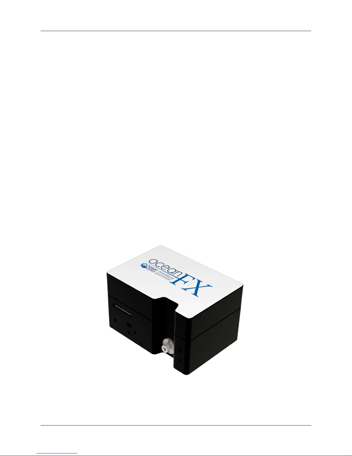
Ocean FX Miniature Spectrometer
User Manual
Amy to r
For Product: OCEAN FX
Document: 226-00000-000-01
Version: 1.3
Page 2

Page 3

AMERICAS & WORLD HEADQUARTERS
Germany
Phone: +1 727-733-2447
Fax: +1 727-733-3962
Sales: info@oceanoptics.com
Orders: orders@oceanoptics.com
Support: techsupport@oceanoptics.com
EUROPE, MIDDLE EAST & AFRICA
Ocean Optics, Inc.
830 Douglas Ave.
Dunedin, FL 34698
USA
Manufacturing & Logistics
4301 Metric Dr.
Winter Park, FL 32792
USA
Phone: +31 26-319-0500
Fax: +31 26-319-0505
Email: info@oceanoptics.eu
Germany : +49 711-341696-0
UK : +44 1865-811118
France : +33 442-386-588
Sales & Support
Geograaf 24
6921 EW Duiven
The Netherlands
Manufacturing & Logistics
Maybachstrasse 11
73760 Ostfildern
ASIA
Phone: +86 21-6295-6600
Fax: +86 21-6295-6708
Email: asiasales@oceanoptics.com
Japan & Korea: +82 10-8514-3797
Ocean Optics Asia
666 Gubei Road
Kirin Tower Suite 601B
Changning District
Shanghai
PRC, 200336
www.oceanoptics.cn
www.oceanoptics.com
Copyright © 2017 Ocean Optics, Inc.
All rights reserved. No part of this publication may be reproduced, stored in a retrieval system, or transmitted, by any means,
electronic, mechanical, photocopying, recording, or otherwise, without written permission from Ocean Optics, Inc.
Trademarks
All products and services herein are the trademarks, service marks, registered trademarks or registered service marks of their
respective owners.
Limit of Liability
Every effort has been made to make this manual as complete and as accurate as possible, but no warranty or fitness is implied. The
information provided is on an “as is” basis. Ocean Optics, Inc. shall have neither liability nor responsibility to any person or entity
with respect to any loss or damages arising from the information contained in this manual.
226-00000-000-01 i
Page 4

Table of Contents
Compliance .................................................................................................................... vi
Warnings & Cautions ..................................................................................................... viii
About This Manual ......................................................................................................... ix
Document Summary .................................................................................................................. ix
Product-Related Support and Documentation ........................................................................... x
Warranty ........................................................................................................................ xi
Chapter 1 ............................................................................................ 1
Introduction ........................................................................................ 1
Product Introduction ....................................................................................................... 1
Product Features ....................................................................................................................... 2
Typical Applications ................................................................................................................... 3
Product Versions ........................................................................................................................ 5
Chapter 2 ............................................................................................ 6
How the Ocean FX Spectrometer Works .......................................... 6
Overview ........................................................................................................................ 6
Chapter 3 ............................................................................................ 11
Installation and Setup ........................................................................ 11
What’s In the Box ........................................................................................................... 11
Ocean FX Installation ..................................................................................................... 12
Software Installation ................................................................................................................... 12
About OceanView ...................................................................................................................... 13
Initial Configuration .................................................................................................................... 13
Configuration for USB or Ethernet Connection .......................................................................... 14
Configuration for WiFi Connection ............................................................................................. 19
Power Sequences ...................................................................................................................... 25
Experiment Setup ...................................................................................................................... 26
Ocean FX Indicator Lights ......................................................................................................... 27
Interchangeable Slits ................................................................................................................. 27
Changing the Interchangeable Slits ........................................................................................... 27
Accessories .................................................................................................................... 29
Cables and Connectors ............................................................................................................. 29
Breakout Box (HR4-BREAKOUT) .............................................................................................. 29
Light Sources, Cuvette Holders and Other Accessories ........................................................... 29
Measurement Techniques – Typical Set-ups .................................................................. 30
Common UV-Vis Applications .................................................................................................... 30
Reflectance & Transmission ...................................................................................................... 31
226-00000-000-01 ii
Page 5

About This Manual
Common UV-Vis Reflectance Applications ................................................................................ 31
Common UV-Vis Transmission Applications ............................................................................. 31
Fluorescence.............................................................................................................................. 32
Common Fluorescence Applications ......................................................................................... 32
Irradiance ................................................................................................................................... 33
33
Chapter 4 ............................................................................................ 35
Ocean FX Operation with OceanView .............................................. 35
Overview ........................................................................................................................ 35
Launch OceanView ........................................................................................................ 35
OceanView Main Screen ................................................................................................ 36
Connect the Ocean FX in OceanView ....................................................................................... 37
Set Acquisition Parameters ........................................................................................................ 38
Continuous and Single Acquisitions .......................................................................................... 38
Save Data .................................................................................................................................. 39
Saved Data Panel ...................................................................................................................... 39
Projects and Methods ................................................................................................................ 40
Spectroscopy Application Wizards ............................................................................................ 40
Dark and Reference Measurements .......................................................................................... 41
Schematic View ......................................................................................................................... 41
Chapter 5 ............................................................................................ 43
Troubleshooting ................................................................................ 43
Overview ........................................................................................................................ 43
Microsoft Windows Operating Systems ..................................................................................... 45
Apple Mac OSX Operating Systems .......................................................................................... 45
Linux Operating Systems ........................................................................................................... 45
Chapter 6 ............................................................................................ 48
Technical Specifications ................................................................... 48
Mechanical Diagram ...................................................................................................... 48
Absolute Maximum Ratings ............................................................................................ 49
Performance Specifications ............................................................................................ 49
Accessory Connectors ................................................................................................... 52
DD4 Accessory Connector ......................................................................................................... 52
I2C .............................................................................................................................................. 54
DB15 Connector Cable (OCEAN FX-CBL-DD4P-DB15P) ........................................................ 54
Chapter 7 ............................................................................................ 56
Calibration .......................................................................................... 56
226-00000-000-01 iii
Page 6

About This Manual
Overview ........................................................................................................................ 56
Wavelength Calibration .................................................................................................. 56
About Wavelength Calibration ................................................................................................... 56
Calibrating the Spectrometer Wavelength ................................................................................. 57
Preparing for Calibration ............................................................................................................ 57
Calibrating the Wavelength of the Spectrometer ....................................................................... 57
Irradiance Calibrations ................................................................................................... 59
226-00000-000-01 iv
Page 7

About This Manual
Tables
Table 1 .......................................................................................................................................... ix
Table 2 ........................................................................................................................................... 2
Table 3 ........................................................................................................................................... 4
Table 4 ........................................................................................................................................... 5
Table 5 ........................................................................................................................................... 5
Table 6 ........................................................................................................................................... 7
Table 7 ........................................................................................................................................... 8
Table 8 ......................................................................................................................................... 12
Table 9 ......................................................................................................................................... 27
Table 10 ....................................................................................................................................... 49
Table 11 ....................................................................................................................................... 49
Table 12 ....................................................................................................................................... 50
Table 13 ....................................................................................................................................... 51
Table 14 ....................................................................................................................................... 51
Table 15 ....................................................................................................................................... 53
Table 16 ....................................................................................................................................... 55
226-00000-000-01 v
Page 8
About This Manual
Compliance
WARNING
This is a FCC Class A product. In a domestic environment, this
product may cause radio interference in which case the user may
be required to take adequate measures.
FCC COMPLIANCE
This equipment has been tested and found to comply with the limits for a
Class A digital device, pursuant to Part 15 of the FCC Rules. These limits
are designed to provide reasonable protection against harmful interference
when the equipment is operated in a commercial environment. This
equipment generates uses and can radiate radio frequency energy and, if
not installed and used in accordance with the instruction manual, may
cause harmful interference to radio communications. Operation of this
equipment in a residential area is likely to cause harmful interference in
which the user will be required to correct the interference at his own
expense.
WARNING
The authority to operate this equipment is conditioned by the
requirement that no modifications will be made to the equipment
unless the changes or modifications are expressly approved by the
manufacturer.
WEEE COMPLIANCE
The WEEE symbol on the product indicates that the product must not be
disposed of with normal household waste. Instead, such marked waste
equipment must be disposed of by arranging to return to a designated
collection point for the recycling of waste electrical and electronic
equipment. Separating and recycling this waste equipment at the time of
disposal will help to conserve natural resources and ensure that the
equipment is recycled in a manner that protects human health and the
environment.
226-00000-000-01 vi
Page 9

About This Manual
TUV CERTIFICATION
This device has been tested and complies with the following standards:
EN 61326-1:2013
CISPR 11:2009.A1:2010
CAN ICES-003, issue 6
EMC 2004/108/EC
RoHS-compliant
ISO COMPLIANCE
Ocean Optics, the industry leader in miniature photonics, has been certified for ISO 9001:2008
certification applicable to the design and manufacture of electro-optical equipment since 2009.
226-00000-000-01 vii
Page 10
About This Manual
Warnings & Cautions
Warnings
This device may cause radio interference or may disrupt the operation of nearby
equipment. It may be necessary to take mitigation measures such as re-orienting,
relocating or shielding the location.
Cautions
Caution: Do not let contaminants get into the bench. Keep the protective cap on the slit
aperture when not connected to an accessory, probe or fiber.
Caution: Only change the slit aperture in a clean environment where contaminants including
dust cannot enter the bench during the procedure.
Caution: Substitution of a component or accessory different from that supplied may result in
measurement error, equipment damage, increased emissions or decreased immunity.
Caution: Repairs should be undertaken only by personnel trained or authorized by Ocean
Optics. The device does not contain any user serviceable parts.
Caution: Do not immerse the device in any fluid, place fluids on top of or attempt to clean with
liquid detergents or cleaning agents. This may cause an electrical hazard. Do not
use if accidental wetting occurs.
Caution: Do not remove any covers. Doing so may increase the risk of electrical shock or
compromise the integrity of the optical components.
Caution: Do not gas sterilize or autoclave this device.
Caution: Consult local codes and ordinances for proper disposal of equipment and other
consumable goods.
Caution: The device and/or accessories may not operate correctly if used or stored outside the
relevant temperature and humidity ranges described in the Technical Specifications.
Caution: Do not use if device is dropped and/or damaged. Have an authorized service
representative check the device before using again.
Caution: Be sure to install any software BEFORE connecting the spectrometer to your PC. The
software installs the drivers required for spectrometer installation. If you do not install
the software first, the system will not properly recognize the spectrometer.
Caution: To ensure reliable operation, it is recommended that the power supply be attached
prior to inserting the USB connector.
Caution: The user of this spectrometer shall have the sole responsibility for any malfunction
which results from improper use, faulty maintenance, improper repair, damage or
alteration by anyone other than Ocean Optics or their authorized service personnel.
226-00000-000-01 viii
Page 11
About This Manual
About This Manual
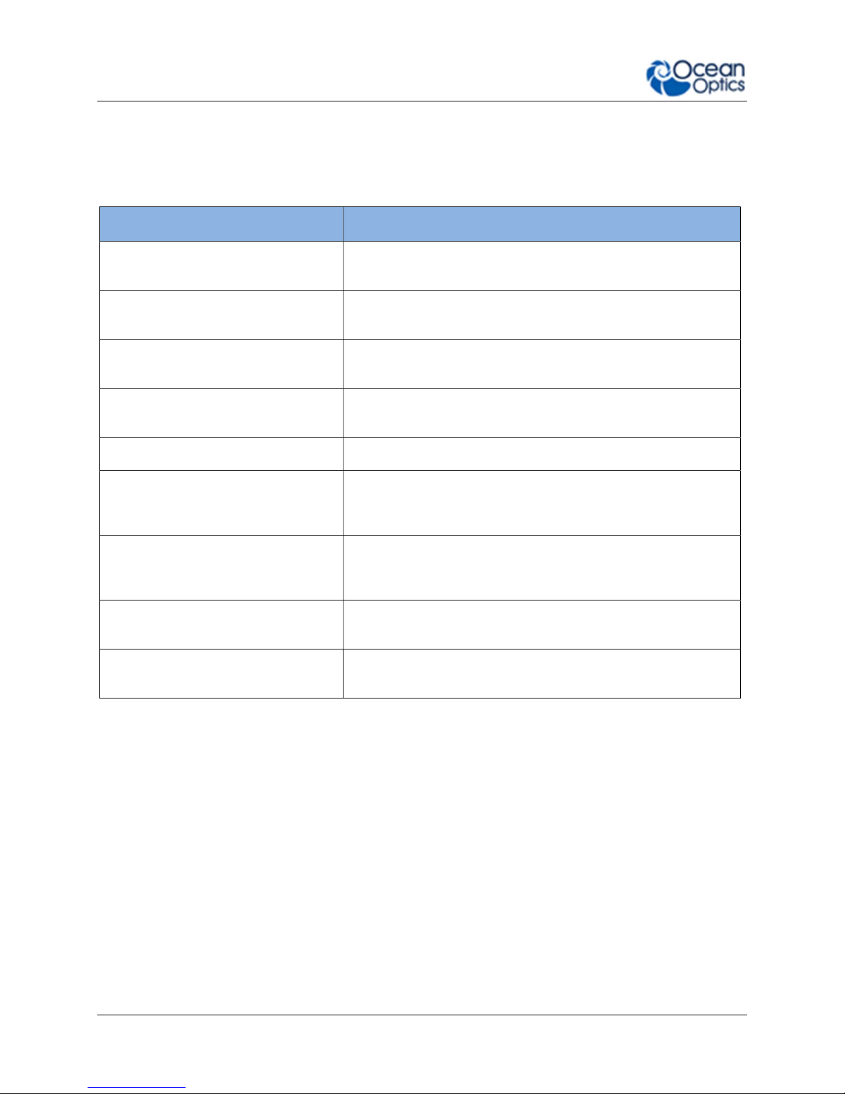
Document Summary
Chapter Description
Chapter 1: Introduction Introduces the product features. Contains descriptive
information about the Ocean FX Spectrometer. It also
provides a list of system requirements, typical applications,
and product versions.
Chapter 2: How the Ocean FX
Spectrometer Works
Chapter 3: Installation and Setup Provides installation instructions, including how to set up the
Chapter 4: Ocean FX Operation with
OceanView
Chapter 5: Troubleshooting Contains recommended steps to isolate and correct common
Chapter 6: Technical Specifications Contains technical specifications and connector pinouts for the
Chapter 7: Calibration Provides information for calibrating the Ocean FX
Describes how the Ocean FX operates, illustrating the various
parts and functions.
Ocean FX with OceanView. Also includes package contents
and typical set-ups for different measurement techniques.
Describes how to use the Ocean FX with OceanView
software, including how to connect, acquire, save and other
basic features.
problems.
Ocean FX Spectrometer.
Spectrometer.
Table 1
226-00000-000-01 ix
Page 12

About This Manual
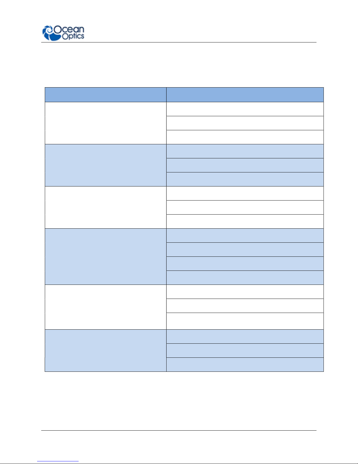
I2C Intelligent Interface Controller
MISO
Master Input, Slave Output
MOSI
Master Output, Slave Input
SPI Serial P
eripheral Interface
Tx Transmit
Vusb
Voltage, USB
FWHM
Full Width Half Maxi
mum
– optical resolution units
CMOS
Complementary metal oxide semiconductor
– type of detector
TEC
Therm
oelectric
Coo
ling
ACRONYMS & SYMBOLS
IEEE Institute of Electronic and Electrical Engineers
Rx Receive
USB Universal Serial Bus
WiFi Wireless Fidelity
CCD Charged Coupled Device - type of detector
Product-Related Support and Documentation
You can access product documentation for Ocean Optics products by visiting our website at
http://www.oceanoptics.com. Go to the Ocean FX product page for general product details,
specifications and application notes. Additional technical documents and programs can be
accessed through the Support tab which includes software downloads, getting started guidance,
frequently asked questions and technical documents for topics including OceanView Software,
light sources, electronic accessories, sampling accessories, fibers & probes, external triggering,
changing the slit size and device driver guidance.
Ocean Optics offers a Glossary of spectroscopy terms to help you further understand your
state-of-the-art products and how they function located in the Knowledge section which also
offers example setups, application blogs, videos through SpectroscopyTV.com and other ways
of learning about spectroscopy.
226-00000-000-01 x
Page 13

About This Manual
Warranty
Our 3-Year Warranty covers Ocean Optics miniature fiber-optic spectrometers, spectral
sensors, light sources and sampling accessories – regardless of the application – from defects
in materials and workmanship from the date of purchase. It also covers fibers and probes for a
full 12 months.
The warranty covers parts and labor needed to repair manufacturing defects that occur during
the warranty period. We also will cover the costs of shipping warranty-related repairs from our
customers to Ocean Optics and from us to our customers. Repairs and upgrades are covered
for manufacturing defects for 6 months from the date of purchase from Ocean Optics.
Normal wear, scratching and cosmetic damage not affecting the performance, bulbs, batteries,
consumables and vendor items are not covered by this Ocean Optics limited warranty. For
vendor items, the manufacturer’s warranty terms are in force and vary from product to product.
These causes are not covered by this warranty: damage caused by accident, misuse – such as
using an incorrect power supply or power current – abuse, product modification or neglect;
damage occurring during shipment; damage resulting from the performance of repairs by
someone not authorized by Ocean Optics; damage caused by installation of parts that do not
conform to Ocean Optics specifications; units not used for their intended purpose; and any
claims made based on misrepresentations of the seller and costs associated with installation of
the unit.
Ocean Optics’ liability is limited to the repair or the replacement, at our option, of any defective
item and shall not include incidental or consequential damages whatsoever. Ocean Optics
reserves the right to replace a discontinued model with a functionally comparable model.
If you require warranty service, please contact the Customer Service Department of Ocean
Optics at +1.727.733.2447 or fill out a Return Merchandise Authorization (RMA) form located in
the Support section of our website.
226-00000-000-01 xi
Page 14

Page 15
Chapter 1
Introduction
Product Introduction
The Ocean FX is a miniature modular spectrometer with enhanced connectivity and onboard
processing that is based upon Ocean Optics’ Cross Czerny-Turner design. Ocean FX is built
using manufacturing techniques that help deliver high thermal stability and low unit to unit
variation without compromising the flexibility and configurability that are the hallmark of the
design. Features such as interchangeable slits, indicator Lights and simpler device connectors
deliver more freedom and less frustration. In addition, Ocean FX now utilizes a USB 3.0
connecter for increased speed and also has 2 new methods of interfacing with the
spectrometer: Gigabit Ethernet and 802.11a/b/g/n WiFi.
226-00000-000-01 1
Ocean FX Spectrometer
Page 16
1: Introduction
Product Features
Fast Acquisition Speed Integration times down to 10µs, acquire and process more
spectral data in less time for faster, more reliable answers
Sensitive
Multiple Configurations Incredibly configurable, with millions of configurations across
Large Onboard Memory Onboard buffering stores up to 50,000 spectra so you will not
Spectra Timestamping All spectra are timestamped
Expanded Connectivity Gigabit Ethernet, WiFi, USB, RS-232 and SPI for easy
On-the-fly Slit Modifications
High Thermal Stability Allows for accurate and repeatable measurements in
Portable Robust Design Compact, rugged and lightweight for use in the lab or in
Responsive from 190 – 1100 nm with great sensitivity in the
UV and NIR
the wavelength range 190-1100nm
miss a single data point
integration into almost any system as well as 8 GPIO for
connection to external devices
User-interchangeable slit allows quick changes to resolution
and throughput allowing one spectrometer to perform multiple
types of experiments such as absorbance and fluorescence.
demanding environments
remote applications
226-00000-000-01 2
Table 2
Page 17
1: Introduction
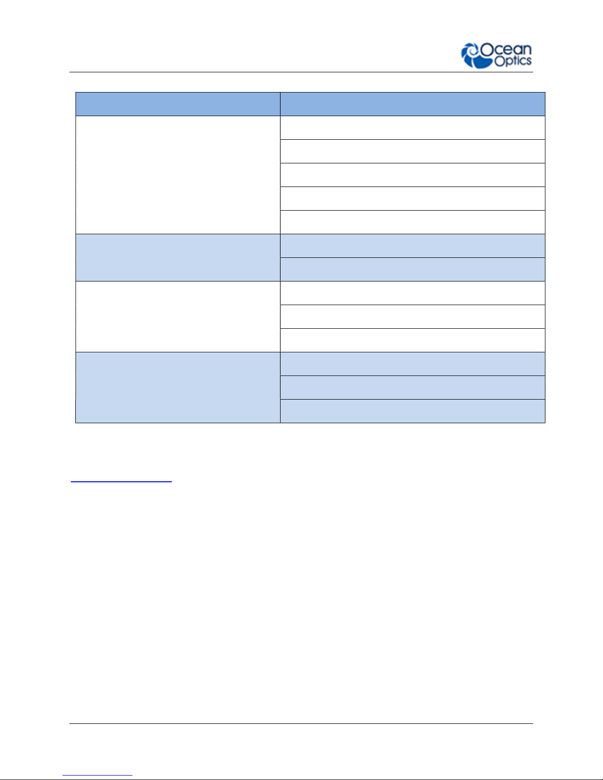
Typical Applications
Application Area Examples
Light Laser LED
Research and Education
Life Sciences
Materials Identification
Laser Characterization
LED Measurement
Light Metrology Measurement
Applied Research
Basic Research
Teaching Labs for Physics, Chemistry, Biomed
Biotechnology
Medical Diagnostics
Protein and Nucleic Acid Analysis
Biomaterial Analysis
Metallurgical Analysis
Polymer Analysis
Semiconductor Materials Analysis
Semiconductors Processing and Thin Film
Metrology
Farm to Table Technologies
226-00000-000-01 3
Plasma Monitoring
Process Endpoint Detection
Thickness Measurement
Agricultural Measurements and Monitoring
Food and Beverage Quality Control
Food Safety
Page 18
1: Introduction
Application Area Examples
Biofuels Analysis
Energy Technologies
Mining and Exploration
Oil and Petroleum Analysis
Photovoltaic Analysis
Solar Simulators
Anti-Counterfeit
Quality Control and Process Monitoring
Environmental Monitoring
Testing and Qualification
Product Identification and Authentication
Defect Identification
Raw Material Inspection
Verification Testing
Air and Water Quality Analysis
Remote Sensing
Volcanic Research
Table 3
You can find more information about applications of UV-Vis spectroscopy and the Ocean FX at
www.oceanoptics.com.
226-00000-000-01 4
Page 19
1: Introduction
Specifications Summary
Spectral range 200 - 1100 nm (configurable within this range)
Optical resolution 2.39 pixels (FWHM)
SNR (single scan) 290:1
Dynamic range (single scan) 5000:1
Integration time 10 µs – 10 seconds
Scan rate (maximum) 4500 scans/second
Thermal stability 0.11 pixels/ C
Entrance slit 5, 10, 25, 50, 100 or 200 µm width slits
Input fiber connector SMA 905 or FC
Table 4
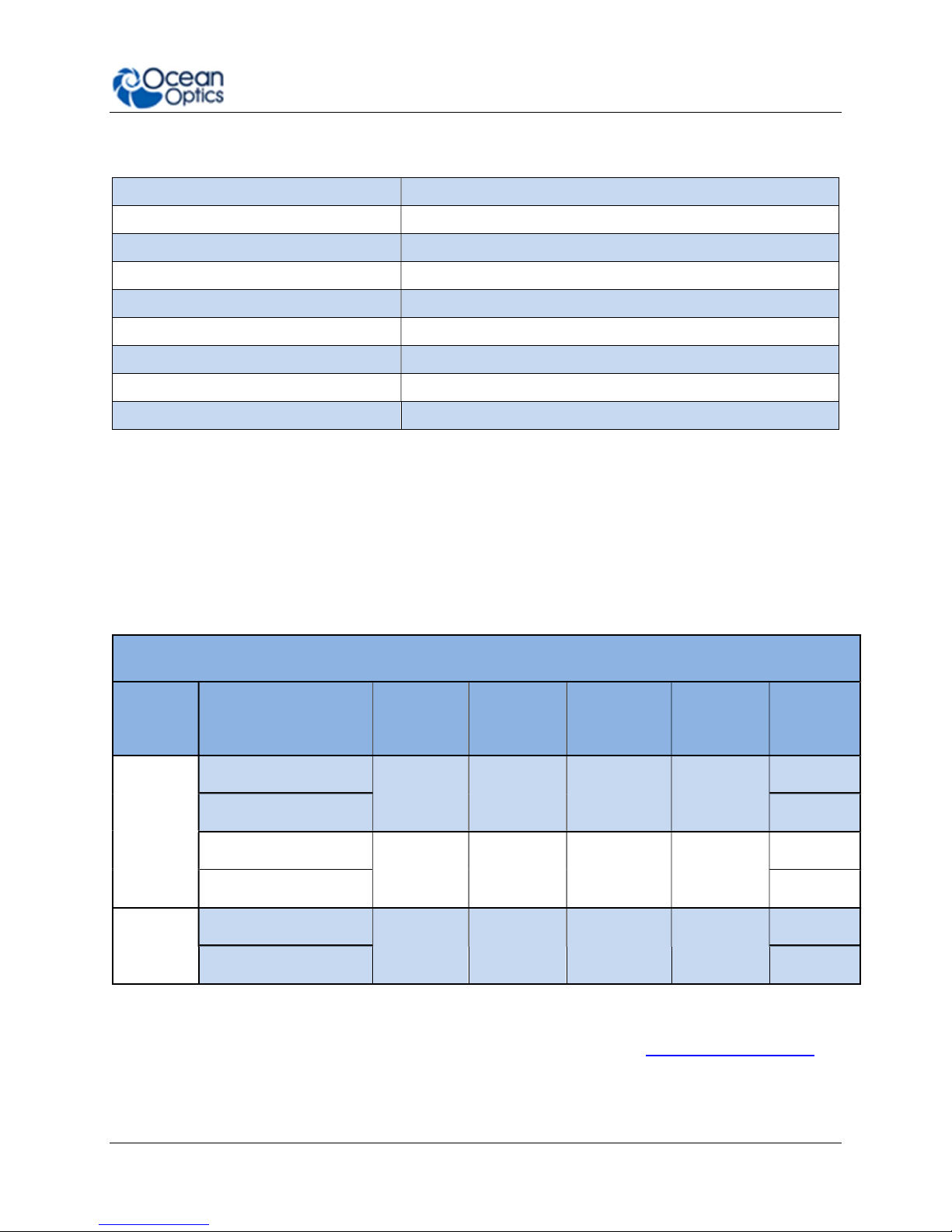
Product Versions
Many variants of the Ocean FX Spectrometer exist. Ocean Optics offers both preconfigured
units as well as custom-configured units, enabling you to order a customized spectrometer
optimized for your application. You can determine spectrometer details by looking at the product
code located on the bottom of your spectrometer.
OCEAN FX Preconfigured Models
Optical
Resolution
(nm)
Grating # Lens
none
L2
none
L2
none
L2
General
Purpose
Extended
Range
Model
OCEAN FX-UV-VIS
OCEAN FX-UV-VIS-ES
OCEAN FX-VIS-NIR
OCEAN FX-VIS-NIR-ES
OCEAN FX-XR1
OCEAN FX-XR1-ES
Range
(nm)
200-850 25 1.5 1
350-1000 25 1.5 3
200-1025 25 2 31
Table 5
Slit
(μm)
For more information and specifications on preconfigured models, see www.oceanoptics.com.
226-00000-000-01 5
Page 20
Chapter 2
How the Ocean FX Spectrometer
Works
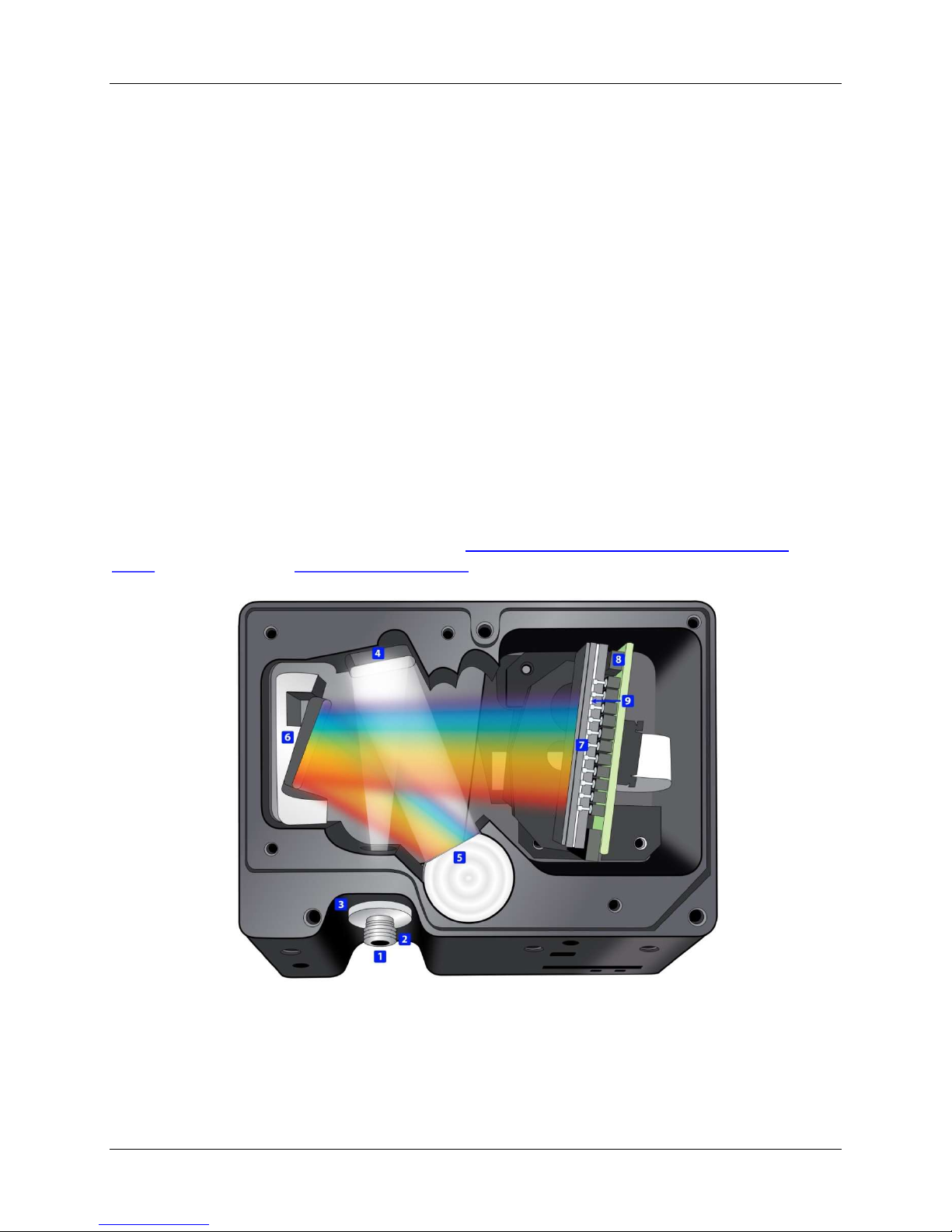
Overview
This section provides an overview of the Ocean FX spectrometer and how it works from light
entering the slit to the communication of the spectrum to a connected device. It also provides an
overview of all the different possible configurations that are possible, designed to help you
optimize your spectrometer for specific applications.
You’ll find more useful information, including a glossary of spectroscopy and spectrometer
terms, on our website at www.oceanoptics.com.
1. Fiber Optic Connector: Light from a fiber enters the optical bench through the SMA
905 Connector. The SMA 905 bulkhead provides a precise location for the end of the
226-00000-000-01 6
Ocean FX Open Bench
Page 21
2: How the Ocean FX Spectrometer Works
optical fiber, slit, absorbing filter and fiber clad mode aperture. While we supply SMA
connectors as standard, FC connectors are also available. See #2 for available options.
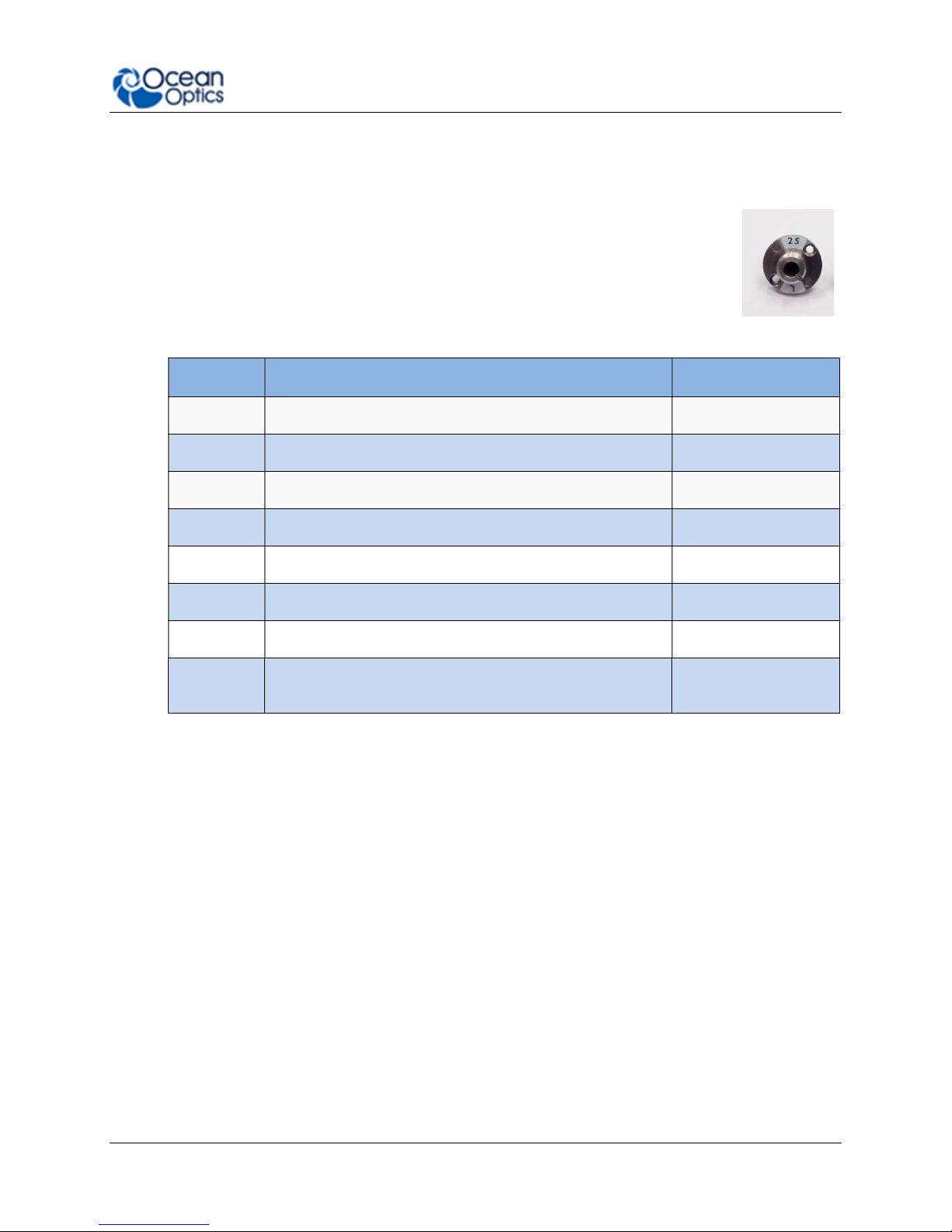
2. Interchangeable Slit: Light passes through the installed slit, which acts
as the entrance aperture. Slits come in various widths from 5 µm to 200
µm and the slit is fixed in the SMA 905 bulkhead to sit against the end of
a fiber. Smaller slit sizes achieve the best optical resolution while larger
slits have higher light throughput. Slit size is labeled on the aperture as
shown in the photo.
Slit Description Pixel Resolution
INTSMA-5 5-µm wide x 1-mm high 3.0 pixels
INTSMA-10
INTSMA-25
INTSMA-50
INTSMA-100
INTSMA-200
INTSMA-000
INTSMA-KIT Interchangeable SMA Kit connectors; 5µm; 10µm; 25µm;
10-µm wide x 1-mm high 3.2 pixels
25-µm wide x 1-mm high 4.2 pixels
50-µm wide x 1-mm high 6.5 pixels
100-µm wide x 1-mm high 12 pixels
200-µm wide x 1-mm high 24 pixels
Interchangeable bulkhead with no slit NA
NA
50µm; 100µm and 200µm
Table 6
Ocean Optics also offers a range of FC connector slits in the same wavelengths, with
the product code INTFC-XXX. An INTFC-KIT is also available. Note that these items are
made to order and have a longer lead time. Contact an Ocean Optics Application Sales
Engineer for more details.
► Procedure
To calculate the optical resolution for your spectrometer:
Find the number of pixels for your detector.
Divide the range of the spectrometer by the number of detector pixels.
Multiply this number by the pixel resolution from the table above.
Example: Optical Resolution with 50 µm slit, 650 nm Spectral range: 650/2048 x 6.5 =
2.1 nm
226-00000-000-01 7
Page 22
2: How the Ocean FX Spectrometer Works
Item Code
Description
Dot 1
Dot 2
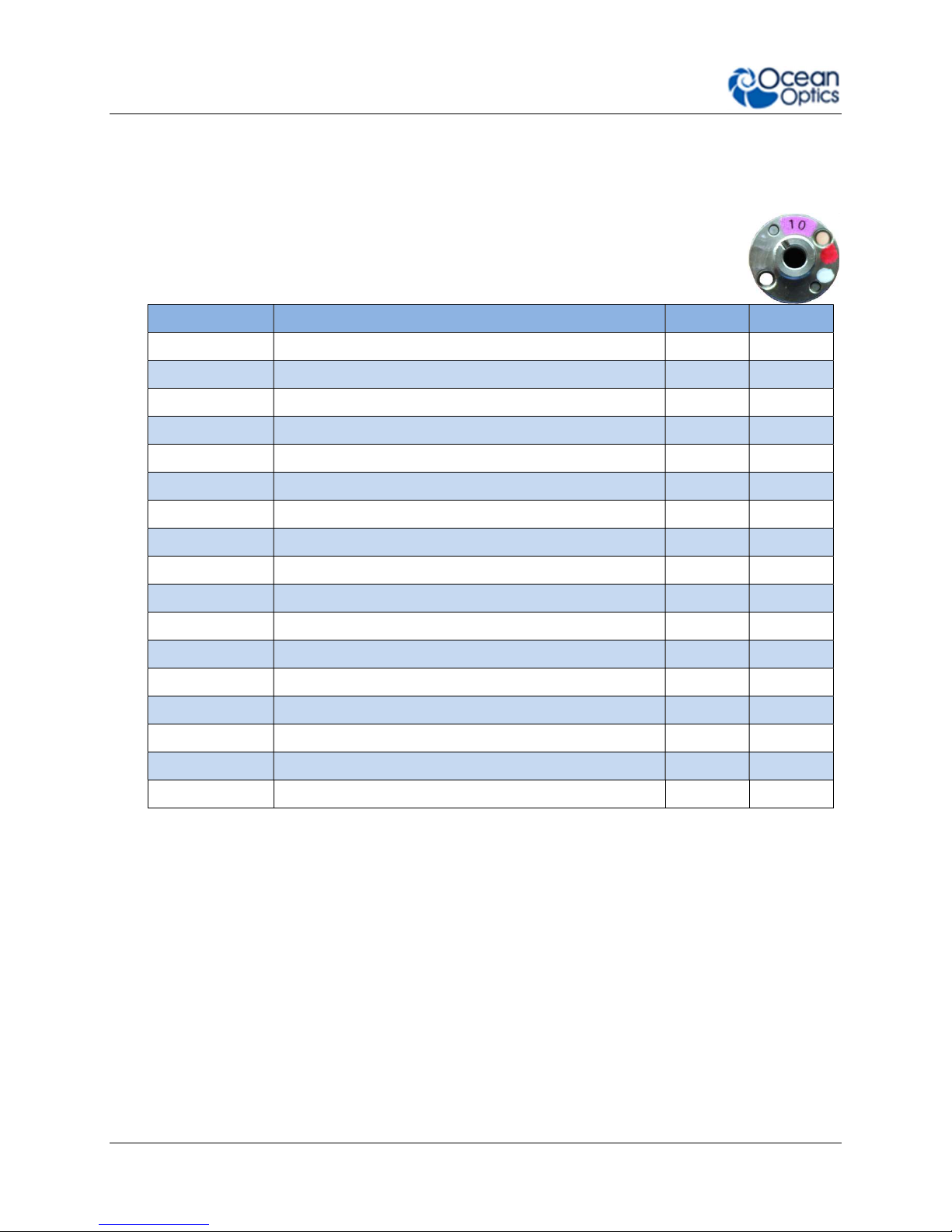
3. Absorbing Filter (optional): If selected, an absorbing filter is installed between the slit
and the aperture in the SMA 905 bulkhead. The filter is used to limit bandwidth of light
entering spectrometer or to balance color. Filters are installed permanently. A filter is for
a specific slit. If you anticipate needing the filter with multiple slit sizes,
then you must specify this at the time you order. You will know which filter
is installed in each slit because of the color-coded dots on the outside as
shown in the figure and described in the table below.
OF1-BG28 Bandpass filter, transmits >325 and <500 nm blue red
OF1-WG305 Longpass filter; transmits light >305 nm black white
OF1-U325C Bandpass filter, transmits >245 and <390 nm white green
OF1-GG375 Longpass filter; transmits light >375 nm red black
OF1-GG395 Longpass filter; transmits light >395 nm white red
OF1-CGA420 Longpass filter; transmits light >420 nm orange white
OF1-GG475 Longpass filter; transmits light >475 nm green green
OF1-OG515 Longpass filter; transmits light >515 nm pink yellow
OF1-OG550 Longpass filter; transmits light >550 nm orange orange
OF1-OG590 Longpass filter; transmits light >590 nm red pink
OF1-RG695 Longpass filter; transmits light >695 nm white blue
OF1-RG830 Longpass filter; transmits light >830 nm black blue
OF1-CGA1000 Nonfluorescing longpass filter, transmits >1000 nm red green
OF1-CGA760 Nonfluorescing longpass filter, transmits >760 nm blue black
OF1-CGA780 Nonfluorescing longpass filter, transmits >780 nm white yellow
OF1-CGA830 Nonfluorescing longpass filter, transmits >830 nm green orange
OF1-CGA475 Nonfluorescing longpass filter, transmits >475 nm yellow pink
Table 7
4. Collimating Mirror (specify Standard or SAG+): Light reflects from the collimating
mirror as a collimated beam toward the grating. You can opt to install a standard mirror
or a NIR-enhancing but UV absorbing SAG+ mirror.
SAG+ mirrors are often specified for fluorescence. These mirrors absorb nearly all UV
light, which reduces the effects of excitation scattering in fluorescence measurements.
Unlike typical silver-coated mirrors, the SAG+ mirrors won’t oxidize. They have excellent
reflectivity — more than 95% across the VIS-NIR.
Specify standard or SAG+ mirrors when ordering your spectrometer.
226-00000-000-01 8
Page 23

2: How the Ocean FX Spectrometer Works
Reflectance vs. Wavelength for Aluminum, Gold, and Silver Mirrors
By Bob Mellish in Wikipedia
5. Grating: In optics, a diffraction grating is an optical component with a periodic structure
that splits and diffracts light into several beams traveling in different directions. The
directions of these beams depend on the spacing of the grating and (most importantly for
spectroscopy) the wavelength of the light. In a spectrometer, the grating acts as the
dispersive element. Most spectrometers make use of a grating to split the incoming
beam of light into its component wavelengths. This makes use of the optical principle of
diffraction; that different wavelengths will be transmitted or reflected from a dispersive
element through varying angles, thereby separating one multi-wavelength beam into
many single-wavelength beams. Typically, a balance must be struck between these two
parameters: as you increase the number of lines/mm on a grating, you increase
resolution but decrease the wavelength range that may be scattered.
Use our online Range and Resolution Calculator to find out how your grating choice
affects spectral range and optical resolution by viewing the grating efficiency curves.
Gratings Showing Light Diffracted into its Constituent Wavelengths
226-00000-000-01 9
Page 24

2: How the Ocean FX Spectrometer Works
6. Focusing Mirror (specify standard or SAG+): This mirror focuses first-order spectra
on the detector plane. Both the collimating and focusing mirrors are made in-house to
guarantee the highest reflectance and the lowest stray light possible. You can opt to
install a standard or SAG+ mirror. As with the collimating mirror, the mirror type needs to
be specified when ordering.
7. Detector Collection Lens (optional): This cylindrical lens is fixed to the detector to
focus the light onto the detector elements. It increases light-collection efficiency and
reduces stray light. It also is useful in a configuration with a large-diameter fiber and slit
for low light-level applications such as fluorescence. Preconfigured Ocean FX
spectrometers with a collector lens are available – look for –ES at the end of the name.
8. Detector: Ocean FX utilizes a Hamamatsu S11639-01 linear silicon CMOS array
detector. Similar to CCD detectors, a CMOS detector also converts incident photons
into an electric charge. But each CMOS detector pixel has an amplifier attached that
transfers the accumulated charge after a measurement has been made to the A/D
converter. CMOS detectors can typically operate at much higher speeds than CCD
detectors.
9. Detector Window: The detector includes a clear, quartz window that often includes an
order-sorting filter designed to block second and third order diffraction effects. Light
reflected off the grating can propagate these 2nd and 3rd order effects at whole multiples
of the incident light. Order-sorting filters reject this stray light only allowing the desired
wavelength through to the detector.
226-00000-000-01 10
Page 25

Installation and Setup
What’s In the Box
Ocean FX Spectrometer
Your Ocean FX spectrometer arrives pre-calibrated and ready to plug and play.
Chapter 3
Universal Power Supply
Your Ocean FX spectrometer comes with an external power supply and includes multicountry plugs.
USB Cable
Cable to connect your spectrometer to a USB port on a computer running on a Windows,
Mac or Linux operating system. The supplied cable supports USB 3.0.
Ethernet Cable
Cable to connect your spectrometer to your network switch. The supplied cable
supports Gigabit speed.
Getting Started Reference Card
The Ocean Optics Getting Started reference will guide you in ways that you can find
further information to configure and use your spectrometer and software.
Wavelength Calibration Data Sheet
Each spectrometer is shipped with a Wavelength Calibration Data Sheet that contains
information unique to your spectrometer. OceanView reads this calibration data from
your spectrometer when it interfaces to a computer.
Warranty Information
Ocean Optics spectrometer warranty is 3 years and this is printed on the packaging box.
226-00000-000-01 11
Page 26

3: Installation and Setup
Ocean FX Installation
The following procedure provides general instructions for getting your new Ocean FX
spectrometer up and running.
Software Installation
Caution
Be sure to install the software BEFORE connecting the spectrometer to your PC.
The software installs the drivers required for spectrometer installation. If you do
not install the software first, the system will not properly recognize the
spectrometer.
If you have already connected the Ocean FX to a computer running on a
Windows platform prior to installing the operating software, consult the
Troubleshooting section for information on correcting a corrupt Ocean FX
installation.
Caution
Be sure that you download the correct software package for your computer
version (32 or 64-bit). See the Frequently Asked Questions in Troubleshooting
section for more information on determining your computer version.
Use OceanView version 1.6.3 and above for Ocean FX. You can use OceanView on the
following operating systems.
Software
OS
OceanView
2000 XP Vista 7 8 8.1 10
√ √ √ √ √ √
Windows Apple Linux
OS X Version
10.5 or later on
Intel processor
Table 8
Any version released for
an x86 or amd64 platform
since 2010
226-00000-000-01 12
Page 27

3: Installation and Setup
Ethernet
USB
About OceanView
OceanView is a spectroscopy software platform that operates on Windows, Macintosh and
Linux operating systems. The software can communicate with Ocean FX devices through USB,
Ethernet or WiFi.
OceanView is a user-customizable, advanced acquisition and display program that provides a
real-time interface to a variety of signal-processing functions. With OceanView, you have the
ability to perform spectroscopic measurements (such as absorbance, reflectance, and
emission), control all system parameters, collect and display data in real time, and perform
reference monitoring and time acquisition experiments. Consult the OceanView manual for
hardware requirements when using OceanView.
Initial Configuration
There are 3 options for accessing the Ocean FX Spectrometer from your computer:
USB port for a local connection (located on the back of the unit)
Ethernet connection to your network (located on the back of the unit)
WiFi connection to your wireless network
226-00000-000-01 13
Rear View of Ocean FX Spectrometer
Page 28

3: Installation and Setup
Configuration for USB or Ethernet Connection
Important Note
To ensure reliable operation, it is recommended that the power supply be
connected prior to inserting the USB or Ethernet connector.
Important Note
For Ethernet to connect properly, the host computer must be wirelessly
connected to the same router as the Ethernet cable or the Wireless
functionality within the host computer must be turned OFF.
1. Install OceanView spectrometer operating software on the destination device prior to
connecting the spectrometer.
2. Connect the Ocean FX power supply to the Ocean FX and wait for the green indicator
light to illuminate. If performing an Ethernet configuration, wait an additional 60
seconds before moving on to step 3.
3. Start the OceanView application.
4. Click “No” for creating a simulation.
5. The Welcome Screen will be displayed. Click the “OK” button.
226-00000-000-01 14
Page 29

3: Installation and Setup
6. Click on the device manager icon.
7. Verify that:
a. “Automatically connect to device” is checked.
b. “Simulate device if none found” and “Automatically connect to remote device” are
not checked as shown below.
Click the Exit button.
8. For USB, connect the supplied USB cable to the USB connector on the Ocean FX and
the destination device. Wait for device drivers to install before progressing.
For Ethernet, connect the supplied Ethernet cable to the Ethernet connector on the
Ocean FX and to a network router.
226-00000-000-01 15
Page 30

3: Installation and Setup
9. Select the OceanView’s “Schematic” view if not already the active view. This can be
done by clicking Schematic Window on the side bar or by choosing Schematic from the
Window tab.
10. The Ocean FX icon will show up in OceanView’s schematic window as shown below.
226-00000-000-01 16
Page 31

3: Installation and Setup
OR
11. If the device does not appear, go back to Device Manager and click the “Rescan” button.
12. Your Ocean FX device will appear in the Device Manager window and in the
schematic view.
13. If the icon is out of focus it indicates that a device is present, but not connected.
226-00000-000-01 17
Page 32

3: Installation and Setup
This can be verified by noting that the “In Use” checkbox does not have a check mark.
Click the “Connect” button. If the “In Use” checkbox is checked already, click the
“disconnect” button and then click the “Connect” button. The check mark will appear in
the box and the icon will no longer be out of focus. Before exiting, click the
“Automatically connect to remote devices” checkbox when using Ethernet.
Continue your setup as described in Experiment Setup section.
For future Ethernet use after configuration, wait 1 minute after powering up
the Ocean FX before opening OceanView.
Important Note
226-00000-000-01 18
Page 33

3: Installation and Setup
Configuration for WiFi Connection
Initial configuration must be done via USB prior to attempting a WiFi
connection.
The host device with OceanView must be connected to the WiFi router.
Important Note
Important Note
Important Note
Before attempting WiFi configuration, the Ocean FX must be powered on for
at least 2 minutes.
1. In OceanView’s schematic mode, right click on the Ocean FX icon and select “Network
Setup” which opens the Network Setup window.
226-00000-000-01 19
Page 34

3: Installation and Setup
2. Select Interface 1. If necessary, click the “Interface Enable” button. If the WiFi settings
do not appear under Interface 1, then close the window and right click again on the
Ocean FX icon and select “Network Setup”. WiFi options will appear under Interface 1.
3. Select Security which will show options in the upper right corner of the screen. Select the
desired security either Open or WPA2. If WPA2 is selected, enter the password or
phrase that corresponds to your wireless router. Click the “Apply” button.
226-00000-000-01 20
Page 35

3: Installation and Setup
4. Then select Wireless Network under Interface 1. Mode will default to Client. Enter the
SSID for the network device and click the “Apply” button.
5. Select Address. Verify the “Enable DHCP” box is checked. If not, check the box.
226-00000-000-01 21
Page 36

3: Installation and Setup
6. Select Multicast. If necessary, click the “Enable Multicast (discovery)” button. Finally,
select Interface 1 and then click the “Save as Defaults” button which will save the
SSID and passphrase.
7. Wait 1 minute and verify that the Ocean FX is within 15 feet of the WiFi router.
8. In Device Manager, verify that network device has been located. If necessary, click the
“Rescan” button to discover the device.
226-00000-000-01 22
Page 37

3: Installation and Setup
9. Verify the USB device is highlighted. Click on the “Disconnect” button for the USB
device.
10. Both devices should now indicate that they are not in use.
11. Highlight the WiFi connected device and click the “Connect” button.
226-00000-000-01 23
Page 38

3: Installation and Setup
12. At this point you may disconnect the Ocean FX from the configuring USB cable. Only
the WiFi connection will be displayed in Device Manager. Check the “Automatically
connect to remote devices” checkbox before exiting. This will allow OceanView to
wirelessly connect to the Ocean FX when OceanView is opened.
13. If device does not appear correctly, consult the troubleshooting section.
Important Note
When using WiFi after initial configuration, wait 2 minutes after powering up
the Ocean FX before opening OceanView.
14. Continue your setup as described in the Experiment Setup section.
226-00000-000-01 24
Page 39

3: Installation and Setup
Power Sequences
Power ON Sequence
Power up the Ocean FX prior to opening controlling software such as OceanView. Before
starting software, the following wait times are needed for proper connectivity operation:
USB: No wait time
Ethernet: Wait 1 minute
WiFi: Wait 2 minutes
Power OFF Sequence
Close the controlling software before powering down the Ocean FX.
226-00000-000-01 25
Page 40

3: Installation and Setup
Experiment Setup
After the Ocean FX spectrometer is connected in OceanView as described above, you may
continue the setup as shown below.
Ocean Optics Ocean FX Fiber Optic Spectrometer Typical Set-up
1. Connect any spectroscopy accessories. To find operating instructions for Ocean FXcompatible products (such as light sources, sampling chambers, and probes) go to the
Technical Documents section of the Ocean Optics website under the Support menu.
2. Attach the fiber to the fiber optic connector on the spectrometer.
If you installed the spectrometer operating software prior to connecting the Ocean FX, the
software automatically installs the Ocean FX drivers. If the drivers do not successfully install (or
if you connected the Ocean FX to the computer before installing the software), consult the
Troubleshooting section.
Important Note
The Ocean FX driver appears as USB2000+ to your computer since a common
driver is used to ensure backwards and forwards compatibility. This does not
affect functionality.
226-00000-000-01 26
Page 41

3: Installation and Setup
Ocean FX Indicator Lights
The Ocean FX features two indicator lights that operate as shown below:
Light Steady Flashing
red Power is on,
unit is booting
or in idle state
green Heartbeat
Table 9
Indicator lights can be turned off in OceanView or by using a firmware command.
Unit is acquiring data
Interchangeable Slits
The Ocean FX offers the capability of changing the slit size to match your measurement and
application needs. You can order additional replacement slits either individually or as a kit (in
various widths from 5 µm to 200 µm).
Changing the Interchangeable Slits
Caution
Only perform in a clean environment where contaminants cannot enter the
bench during the procedure.
Important Note
If your application requires an absorbing filter, one will be needed for each slit
size.
226-00000-000-01 27
Page 42

3: Installation and Setup
Slit
Important Note
When changing the slit, there is no need to perform a wavelength calibration on
the spectrometer. Just install and start measuring.
► Procedure
1. Find the SMA connector. If a fiber or protective cap is attached, remove it.
2. Use the Allen key to remove the 2 the screws attaching the slit to the spectrometer.
3. Pull the slit out of the spectrometer. This process is made easier by attaching the
protective cap first.
4. Using the guide pins for proper alignment, put the new INTSMA slit connector into the
spectrometer with the key of the connector on the left side.
5. Install the 2 screws again. Use the Allen key to tighten the screws carefully (do not overtighten).
6. If necessary, remove the protective cap and connect the fiber again.
226-00000-000-01 28
Page 43

3: Installation and Setup
Accessories
Ocean Optics provides a range of standard cables and accessories that connect the Ocean FX
to our large range of sampling and light source accessories utilizing the DD4 connector on the
front of the Ocean FX spectrometer. Items specifically designed for the Ocean FX are described
here; they are not provided with the Ocean FX spectrometer and must be purchased separately.
Visit us at www.oceanoptics.com for a complete list of products available for all your
spectroscopy needs.
Cables and Connectors
Cables are available to connect your Ocean FX Spectrometer to accessories such as light
sources. Cable pinouts and descriptions are located in the Technical Specifications chapter.
Breakout Box (HR4-BREAKOUT)
The Breakout Box is a passive module that separates the signals from the Ocean FX’s DD4 40pin connector to an array of standard connectors and headers, enabling functionality with a wide
range of accessories. In addition to the accessory connector, the breakout box features a circuit
board based on a neutral breadboard pattern that allows custom circuitry to be prototyped on
the board itself. See the Ocean Optics website for installation and operation instructions.
Light Sources, Cuvette Holders and Other Accessories
Ocean Optics supplies a large range of accessories for use with our spectrometers. This
includes:
Fibers
Light Sources
Integrated Sampling Systems
Cuvettes, including microfluidic cuvettes
Filter Holders & Filters including Low Pass, Band Pass and High Pass
226-00000-000-01 29
Page 44
3: Installation and Setup
Measurement Techniques – Typical Set-ups
The Ocean FX, in conjunction with Ocean Optics light sources and sampling accessories, can
be used for many different measurement techniques. One of the key advantages of modular
fiber optic spectroscopy is that you can change components of the system without having to buy
a whole new system. Here, we show a range of typical UV-VIS set ups for basic spectroscopy
techniques. Additional measurement techniques are presented on the Ocean Optics website.
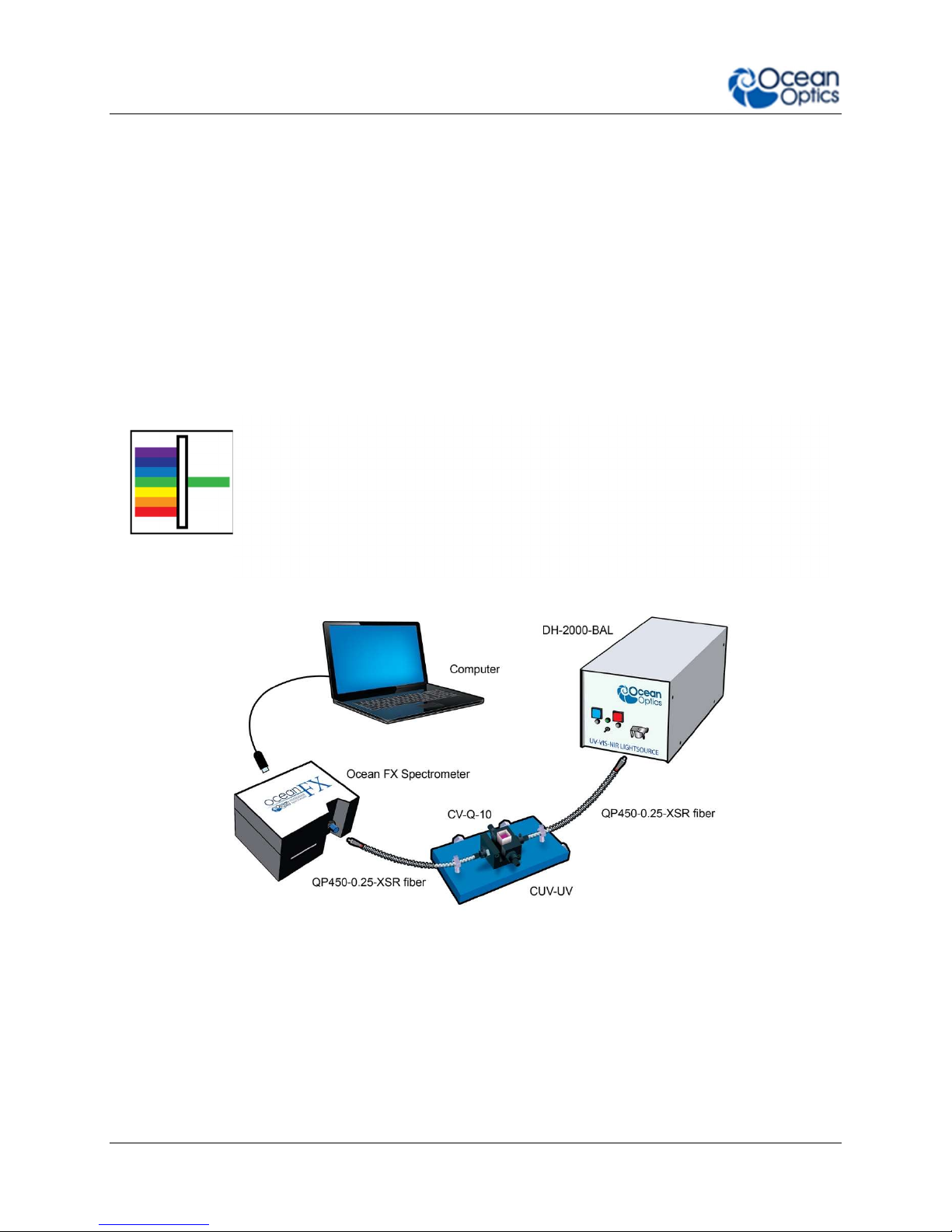
Absorbance
Absorbance is typically a relative measurement, comparing the spectrum
from the sample to that of a reference. Absorbance is commonly used for
concentration measurements and for identifying components in mixtures.
The absorbance measurement scales the response logarithmically.
Connect the to our cuvette accessories via the SMA Adaptor accessory to
take a liquid sample Absorbance measurement, or mount it directly against
the sample with a light source on the opposite side for solid sampling.
Common UV-Vis Applications
Quantification of DNA & proteins in life science samples
Concentration of solutions & gaseous samples
Identification of trace gases in a mixture
226-00000-000-01 30
Typical Absorbance Set Up
Page 45

3: Installation and Setup
Reflectance & Transmission
Reflectance spectroscopy compares the relative level of light reflected off
a sample compared with a reference (given as a percentage of the
reference spectrum at each wavelength). A reflectance standard is used to
set the reference level of 100%. Transmission is similar but compares the
light transmitted through a sample relative to a reference rather than
reflected off it. Typically, reflectance uses a fiber optic probe attached to a
light source and a spectrometer, but measurements can also be done both
in free-space or with the SMA Adaptor accessory. Transmission setups
are usually the same as Absorbance setups.
A Reflectance Set Up with Probe, Reflectance Standard and Probe Holder
Common UV-Vis Reflectance Applications
Diffuse and Specular Color Measurements
Process control for Surface quality of metals
Thin film and semiconductor metrology
Common UV-Vis Transmission Applications
Turbidity measurements of chemical solutions
Measuring the transmission efficiency of optics and glass
226-00000-000-01 31
Page 46

3: Installation and Setup
Fluorescence
Fluorescence is a technique where a sample is excited with a light
source and fluorescent light emitted from the sample at a higher
wavelength is measured by the spectrometer. Typically the excitation
source is applied at 90º to the sample to minimize light from the
excitation source reaching the spectrometer. Filters are used to block
lower wavelength light from reaching the detector. Spectrometers
used for fluorescence typically have a large slit, sacrificing resolution
for throughput sensitivity.
Typical Fluorescence Set Up with an LED Excitation Source at 90º
Common Fluorescence Applications
Identifying proteins using fluorophores
NADH fluorescence
Remote sensing of chlorophyll
Medical diagnosis of tumors and tissue types
Detection of anti-counterfeiting tags
226-00000-000-01 32
Page 47

3: Installation and Setup
Irradiance
Irradiance is the technique of measuring the total energy of light at a
given wavelength, either relative to the spectral output of a known
source (relative irradiance) or in absolute units of power or energy
(absolute irradiance). This is used widely in light metrology, color
measurement and environmental science. Absolute irradiance
measurements require an irradiance-calibrated spectral device. This
can be done in the factory for some configurations or by using a
calibration lamp in the lab or field. Every time a set-up is changed, the
device used must be recalibrated.
Typical Relative Irradiance Set-up for Measuring Light Power Output of an LED Using and
226-00000-000-01 33
Integrating Sphere
Page 48

3: Installation and Setup
Typical Set-up for an Absolute Irradiance Measurement Using Field Calibration with a
Calibrated Light Source
Common Irradiance Applications
Measuring the radiant output of lamps and LEDs
Measuring color using relative irradiance
Measuring the color rendering index (CRI)
Measuring UV exposure for health and safety
226-00000-000-01 34
Page 49

Chapter 4
Ocean FX Operation with
OceanView
Overview
The following information enables you to perform the basics of acquiring and saving data with
your Ocean FX Spectrometer and OceanView software. More detailed information about
OceanView is in the OceanView Manual.
Launch OceanView
Once you have installed your software and connected your spectrometer, start OceanView
which will display the Welcome Screen.
The OceanView Welcome Screen (Version 1.6)
Quick View - Displays the spectrum in Quick View mode showing raw, unprocessed
data. This is uncorrected for instrument response vs. wavelength. Quick View shows you
a live shot of what the Ocean FX is “seeing”. From Quick View you can launch
application wizards or construct your own method.
Load a Saved Project - Loads a previously saved project. Click Restore Last Session
to reload the schematic and views as they were when the software was last closed.
Spectroscopy Application Wizards – Use this function to set up a measurement using
simple step-by-step wizards. A large range of applications are available.
226-00000-000-01 35
Page 50

4: Operation
OceanView Main Screen
No matter what route you take on start up, you will soon end up on the OceanView main screen.
This is where you can set and view acquisitions, save data, load data and save projects.
1. Acquisition Group
Window
2. Schematic View Schematic view graphically displays the flow of information from
3. View Display Display your data, view, save and display controls, as well as other
4. Global Controls Control all spectrometers synchronously, save projects, and start a
5. Saved Data Displays data saved in the active save file path. Preview data,
Use to set acquisition parameters such as integration time.
Controls the spectrometer acquisition.
the spectrometer to the view. Use nodes to mathematically modify
the data to create processed measurements (methods).
features such as peak finder and quick dark & reference.
new application wizard.
store notes and load overlays directly to the active view. Click to
open.
226-00000-000-01 36
Page 51

4: Operation
Connect the Ocean FX in OceanView
Refer to the Initial Configuration section for the initial steps for your new Ocean FX
spectrometer. Once the initial configuration is done, follow the steps below for when you
connect your device.
The Ocean FX should automatically appear when you start OceanView and should be acquiring
with the default acquisition parameters. If you do not see a signal or the Ocean FX icon on the
schematic you may need to rescan for spectrometers.
► Procedure
To rescan for attached devices,
1. Click on the Device Manager icon ( ).
2. Click Rescan. The spectrometer should automatically connect.
226-00000-000-01 37
Page 52

4: Operation
Set Acquisition Parameters
Set Acquisition parameters in the Acquisition Group Window to control the spectrometer. This
window may be minimized when you first start OceanView. You can either expand or open a
new window from the menu (Window | Acquisition Group). An active acquisition is required for
the Acquisition window to appear. Functions available to control in the Acquisition window
include the following:
Integration Time – Sets the integration time, the time over which the detector
captures incident light. At the end of the integration time the accumulated signal is read
from the detector by the electronics.
Averaging – Signal, especially at low levels, is often significantly impacted by noise.
Averaging several spectra together reduces the impact of noise and provides a cleaner
result.
Boxcar – Boxcar is a form of averaging across pixels. It applies a rolling average to
multiple adjacent pixels to help smooth the spectral response and reduce the impact of
noise.
Electric Dark Correction (on/off) – There are pixels on the detector that are kept
deliberately dark. Dark correction subtracts the signal from these dark pixels to reduce
the impact of thermal noise, which produces a baseline signal from the detector.
Non Linearity Correction (on/off) – Detectors do not have a completely linear
response. As they approach saturation, typically their efficiency reduces.
Stray Light Correction – An advanced user option that allows you to set a 1 or 2-term
polynomial correction for stray light correction.
Trigger Modes – Sets triggering mode.
Strobe/ Lamp (on/off) – Use this function to turn an attached light source on or off.
GPIO Controls – Can be used to control compatible accessories or custom hardware.
Can be set to three states, on, off and alternate.
Controls that appear in this window depend on the spectrometer model. You can add and
remove acquisition controls from this window.
Continuous and Single Acquisitions
There are two sets of controls for taking or pausing acquisitions. The set on the Acquisition
group window allows you to control each device individually. The set on the top bar is a global
control that will allow you to start and pause all devices currently attached.
226-00000-000-01 38
Aquire data continuously
Take a single acquisition and then pause
Pause all acquisitions.
Page 53

4: Operation
Save Data
Configure Saving, set saving parameters and file type, file directory and file naming
convention. Once selected, the file directory will persist until changed.
Start saving data. Turns red when save is active. If saving data continuously, click when red
to stop saving. Will only activate saving for acquisitions attached to that particular view.
Global Save. Activates all configured saves across all views. Use to save data from multiple
devices at the same time.
By default OceanView will save data as a single “snapshot” acquisition. By configuring the save
you can set the save behavior to fit your measurement needs, from single snap shots to a
continuous stream of data over time.
Saved Data Panel
The saved data panel lets you see your data as it is saved and preview data. It also makes it
simple to add overlays of saved data to your screen.
226-00000-000-01 39
Saved Data Panel
Page 54

4: Operation
1. Saved Files List of saved files currently in the saved directory arranged by name or date.
2. Preview Shows a preview of the saved spectra, time series or appended series saved data
can be stepped through acquisition by acquisition using the controls above the
saved files list.
3. File Path Set the file directory.
4. Overlay Set the previewed spectra as an overlay on the active view.
5. Notes Enter notes about the saved spectra. Notes are saved with the same file name as
a separate TSV file. These can be viewed or edited with any text viewer such as
notepad.
Projects and Methods
OceanView makes it easy to save and load projects and methods. We define a project as a
measurement set up made with a particular spectral device. If the software cannot find the
device, it will load this as a method and prompt the user to select a substitute device from those
selected.
Click to save a project. Alternatively select File | Save Project from the menu. Saves all
view and schematic parameters to a single ASCII file.
Load a project or method.
Spectroscopy Application Wizards
Click this button to set up a measurement using simple step by step wizards. A large
range of applications is available.
Application Wizard Window
226-00000-000-01 40
Page 55

4: Operation
Dark and Reference Measurements
Dark and reference measurements are commonly used in spectroscopy.
Dark Measurements – subtract a background signal from the spectrum. This can be
considered the removal of a constant error. Typically this is done when the light source
is off to remove any background from the ambient environment, hence the name dark.
Reference Measurements – make the signal relative to the reference. Consider this a
normalization of the signal against a reference. Typically this is taken with a reference
sample and the light source turned on. This lets you look at the relative spectral change
compared to a reference sample.
Most often you will set up your measurement with the reference and dark through the
application wizards. The wizards will prompt you to take your reference and darks. Alternatively
you can use the quick dark and quick reference features. Once a dark and/or reference
measurement has been set, you can update it with the controls on the top bar of the view.
Quick Reference – click to take a reference and set up a new view. After clicking it will
prompt the user to take a dark.
Quick Dark – click to take a dark measurement and sets up a new Quick View minus dark
view.
Reference – click to update the stored reference measurement.
Dark – click to update the stored dark measurement.
Schematic View
226-00000-000-01 41
Page 56

4: Operation
The schematic view is a graphical interface that allows you to move from device through to
processed data. There are a few basic components to consider.
Devices – Each spectrometer will appear as a separate device. Right click to open a
menu that can generate an acquisition, control a TEC (if applicable) and add other device
controls.
Acquisitions – A spectrometer can output one acquisition per detector channel. Right
click to open menu.
Nodes – These are the building blocks of the schematic view. They are all various
functions that take data in and provide an output. To make a node, right click on the
schematic background. Each node can be configured by double clicking on the node. To
join nodes press ctrl, click and drag (windows).
Views – These are a type of window that displays data. To generate a new view right
click on the schematic background.
More information about schematic view including detailed descriptions of the available nodes
can be found in the OceanView Installation and Operation Manual.
226-00000-000-01 42
Page 57

Chapter 5
Troubleshooting
Overview
Sometimes things do not go to plan. If not, do not hesitate to contact us and our Tech Support
team will leap into action. Some typical questions are answered here. For more information,
consult the FAQs on the Ocean Optics website.
Frequently Asked Questions
How do I know my spectrometer has power?
The red LED on the spectrometer should be on steadily if the unit is receiving power.
How do I know my spectrometer is transmitting data?
The red LED on the spectrometer flashes when transmitting data.
How do I check the configuration of my spectrometer?
Check the label on the bottom of your spectrometer. You can also check your configuration
using your spectrometer operating software. In OceanView, open the Schematic window and
double click the spectrometer icon.
I am installing OceanView but I need a product key. Where can I
find this?
The product key was sent to the contact e-mail on the sales order when you purchased your
OceanView license. Contact info@oceanoptics.com for more information. You’ll need your sales
order number, quotation number, the serial number of the spectrometer that was purchased with
the software, and, if known, the e-mail address under which your product key was created to
recover your key.
226-00000-000-01 43
Page 58

5: Troubleshooting
How do I determine whether my Windows computer is 32-bit or 64bit?
Errors can occur if you download the wrong version of software (32-bit or 64-bit). Go to the
Properties or Settings window and find system settings.
I connected the USB cable and started OceanView but I do not see
my spectrometer attached.
Use the Rescan button in the Device Manager to rescan for attached devices.
I am having trouble installing the drivers. What should I do?
Hardware device driver installation is usually seamless on Microsoft Windows operating
systems and should happen in the background when you connect your spectrometer to a
computer with the software installed. However, some Windows systems require a bit more care
when connecting your spectrometer for the first time.
If your spectrometer is not recognized by OceanView on your computer, you need to manually
install the spectrometer drivers. See your OceanView manual for this procedure. Also consult
the Correcting Device Driver Issues document on the Ocean Optics website.
226-00000-000-01 44
Page 59

5: Troubleshooting
I connected the Ocean FX to the computer before installing my
spectroscopy operating software to install the drivers. What do I
do now?
The steps to take to resolve this issue differ, depending on your computer’s operating system.
Microsoft Windows Operating Systems
Important Note
If these procedures do not correct your device driver problem, you must obtain
the Correcting Device Driver Issues document from the Ocean Optics website.
Remove the Unknown Device from Windows Device Manager
► Procedure
1. Open Windows Device Manager. Consult the Windows operating instructions if needed.
2. Locate the Universal Serial Bus Devices option and expand the Universal Serial Bus
Devices selection by clicking on the "+" sign to the immediate left.
Important Note
Improperly installed USB devices can also appear under the Universal Serial Bus
Controller option. Be sure to check this location if you cannot locate the unknown
device.
3. Locate the unknown device (marked with a large question mark). Right-click on the
Unknown Device listing and select the Uninstall or Remove option.
4. Click the OK button to continue. A warning box appears confirming the removal of the
Unknown Device. Click the OK button to confirm the device removal.
Disconnect the Ocean FX from your computer and then re-connect the spectrometer to your
computer. The system should now able to locate and install the correct drivers for the USB
device.
Apple Mac OSX Operating Systems
Since there are no device files for the Ocean FX Spectrometer in a Mac operating system, you
should not encounter any problems if you installed the spectrometer before the spectrometer
operating software.
Linux Operating Systems
For Linux operating systems, simply disconnect and then re-connect the USB cable in the
spectrometer.
226-00000-000-01 45
Page 60

5: Troubleshooting
I have both SpectraSuite and OceanView installed. Will my
spectrometer work with both?
Ocean FX only works with OceanView 1.6 and later.
I’m attempting to connect via Ethernet but I cannot see the
spectrometer. What do I do?
Connect the spectrometer to the computer utilizing the USB cable. Using OceanView, verify the
following:
In Network Connections:
Interface 0 (network) is enabled.
DHCP is enabled for Interface 0.
In Device Manager:
See if device is displayed with an Ethernet connection/address. If not, rescan.
If device is displayed but not connected, click the “connect” button.
I’m attempting to connect via WiFi, but I can’t see the
spectrometer. What do I do?
Initial setup must be done using the USB cable. If that has already been done, verify that the
computer with OceanView resides on is on the same network and subnet as the spectrometer.
Connect to the spectrometer utilizing the USB cable. Using OceanView, verify the following:
In Network Connections:
Interface 1 (WiFi) is enabled.
DHCP is enabled for Interface 1.
Security is set up with correct SSID and passphrase.
In Device Manager:
See if device is displayed with a WiFi connection/address. If not, rescan.
If device is displayed but not connected, click the “connect” button.
I configured my device via USB and am trying to connect to WiFi.
Device manager shows the USB connection and then shows an
error message “Error while communicating with the device.
Reconnect device and rescan devices.”
Verify the device is properly connected to its power source. In Device Manager, unselect
“automatically connect to devices”. Rescan. Once the device is displayed in the window, click
“Connect” button. The device will appear. Reselect “Automatically Connect to Devices” option.
226-00000-000-01 46
Page 61

5: Troubleshooting
Product Upgrades, Repairs and Servicing
Occasionally, you may find that you need Ocean Optics to make a change or an upgrade to
your system. To facilitate these changes, you must first contact Customer Support and obtain a
Return Merchandise Authorization (RMA) number. Please contact Ocean Optics for specific
instructions when returning a product.
Repairs
Sometimes accidents happen! If you need to return your Ocean Optics Product for repair, here
is what to do:
► Procedure
1. Contact us to speak to an Ocean Optics representative about the problem. If it is determined
that the product must be returned, the representative will issue an RMA number.
2. Package your product, ideally in the original packaging, and return it to Ocean Optics, along
with the RMA number that you received.
Important Note
For RMA returns under warranty we will organize and pay for shipping both
ways. For accidental damage, you only pay to have the product delivered to your
closest Ocean Optics or OOI Distributor Office.
Upon careful examination, we’ll advise you with an estimate. When your product is ready, it will
be returned to you.
Servicing
To keep your instrument in tip top shape we recommend yearly wavelength recalibration.
Contact your local representative to find out more about service availability and cost. We offer
the following services:
Wavelength Calibration
Absolute Irradiance Calibrations
226-00000-000-01 47
Page 62

Technical Specifications
Mechanical Diagram
Chapter 6
226-00000-000-01 48
Ocean FX Outer Dimensions
Page 63

6: Technical Specifications
Absolute Maximum Ratings
Input Voltage (Vin, VBatt, GPIO) 0 to +5.5V
Input Voltage (RS232) +/- 25V
Input Voltage (I2C, SPI, Other I/O) 0 to +3.6V
Table 10
Performance Specifications
Storage Temperature -30°C to +70°C
Storage Humidity 0 to 90% RH non-condensing
Operating Temperature 0°C to +50°C
Operating Humidity 0 to 90% RH non-condensing
Recommended Frequency of Calibration The optical calibration should be
performed annually
Ethernet Gigabit transfer rate
USB 3.0, Type C connector Up to 5Gbps data rate
WiFi 802.11 a/b/g/n
Table 11
226-00000-000-01 49
Page 64

6: Technical Specifications
Electrical Characteristics
PARAMETER CONDITIONS MIN TYP MAX UNITS
Input Current (Note 1) +5.0V, external power supply 0.9 2.5 A
Supply Voltage (Vin) 4.75 5.0 5.25 V
GPIO Logic Input Low 0.9 V
GPIO Logic Input High 2.4 V
GPIO I
GPIO Output Low I
GPIO Output High I
GPIO DAC Resolution 12 Bits
GPIO DAC Output Range 0 5 V
I2C / SPI Logic Level I2C pullup resistor onboard 3.3 V
RS232 Output High 5.0 5.4 V
RS232 Output Low -5.0 -5.4 V
Other I/O Voltage Range 3.3 V
SOURCE
/ I
1.6 mA
SINK
= 1 mA 0.4 V
SOURCE
= 1 mA 3.1 V
SOURCE
Table 12
Note 1: Maximum input current includes 1.0A for powering accessories through the DD4 connector. If no accessories are powered through
this connector, then maximum input current drops to 1.5A.
226-00000-000-01 50
Page 65

6: Technical Specifications
Optical and Spectroscopic Characteristics
PARAMETER MIN TYP MAX UNITS
Detector Response Range (note 2) 200 1100 nm
Integration Time 10 10E6 µs
Single Scan Dynamic Range 6423
System Dynamic Range (Note 3) 7.3E7
Single Scan Signal-to-Noise 290
Resolution (FWHM) (Note 4) 2.39 nm
Stray Light (Note 5) 1.9 a.u.
Max Scan Rate 4500 Scans
Buffer Depth 50000 Spectra
Thermal Stability 0.11 Pixels/°C
Trigger Jitter 21 ns
Table 13
Note 2: Spectral range for each spectrometer will be determined by specific features of the optical components.
Note 3: Dynamic range of the system is the range of the detectable light level and can be thought of as the maximum detectable light level
Note 4: Optical resolution of a spectrometer, measured as full width at half maximum (FWHM), depends on the groove density of the grating
Note 5: Stray light is reported here as the average of the stray light measured across 5 regions of the systems wavelength range.
at the minimum integration time divided by the minimum detectable light level at the maximum integration time.
and the diameter of the entrance optics (optical fiber or slit). A G01 600/300 grating and 5 µm slit is used for this measurement.
Mechanical Specifications
PARAMETER SPECIFICATION
Spectrometer Topology Asymmetric Crossed Czerny-Turner
Input Fiber Connector SMA 905 or FC/PC
Entrance Slit 5, 10, 25, 50, 100, or 200 µm slits. (Slits are optional. In the absence of a
slit, the fiber acts as the entrance slit.)
Gratings Specifications vary by grating choice
Physical Dimensions 88.9 mm x 63.5 mm x 52.4 mm
Weight 0.4 kg (14.1 oz)
Mounting No restrictions on mounting. Can be mounted at any angle or position.
Table 14
226-00000-000-01 51
Page 66

6: Technical Specifications
PIN#
SIGNAL NAME
VOLTAGE
DESCRIPTION
Accessory Connectors
DD4 Accessory Connector
The Ocean FX features a 40-pin Accessory Connector, located on the front of the unit as
shown:
DD4
connector
Location of Accessory Connector
The Ocean FX features a 40-pin Accessory Connector (Part Number: DD4RA40JA1) that has
two mating connectors available: DD4PA40MA1 (right angle) and DD4BA40WA1 (vertical).
Pin 1 is on the right when viewing the 40-pin Accessory Connector from the front of the
spectrometer. This connector is used to connect sampling and light sources to the Ocean FX.
DD4 Accessory Connector Pinout
1 GND 0 System Ground
2 IO_TRIG_EXT +3.3 Programmable Hardware Trigger
3 IO_STROBE_CONT_EXT
4 IO_STROBE_SNGL_EXT +3.3 Programmable Single Strobe
5 LAMP_EN +3.3 Programmable Discrete Output
+3.3 Programmable Continuous Strobe
226-00000-000-01 52
Page 67

6: Technical Specifications
PIN#
SIGNAL NAME
VOLTAGE
DESCRIPTION
6 GPIO_0 +3.3/+5.0 General Purpose Software Programmable Digital
7 GPIO_1
8 GPIO_2
9 GPIO_3
10 GND
11 GPIO_4
12 GPIO_5
13 GPIO_6
14 GPIO_7
15 GND 0 System Ground
16 SPI_SCLK +3.3 Master Clock. See SPI Below.
17 SPI_MOSI +3.3 The SPI Master Out Slave In (MOSI) signal is for
18 SPI_CS +3.3 SPI Chip Select signal. See SPI Below.
19 SPI_ MISO +3.3 The SPI Master In Slave Out (MISO) signal is for
20 GND 0 System Ground
21 I2C4_SCL +3.3 I2C Master Clock. See I2C below.
22 I2C4_SDA +3.3 I2C Master Data. See I2C below.
23 GND 0 System Ground
24 RS232_TX -6 to +6 RS232 Transmit Signal
25 RS232_RX -25 to +25 RS232 Receive Signal
26 RS232_CTS -6 to +6 RS232 Clear To Send
27 RS232_RTS -25 to +25 RS232 Request To Send
28 IO_RESET# +5.0 Pull Low to reset device
Inputs/Output, Analog Output. Digital Outputs are
3.3V. Analog Outputs Can Be Programmed To 2.5V
or 5.0V Max.
communications to other SPI peripherals. See SPI
below.
communications to other SPI peripherals. See SPI
below.
29 IO_PWR_DIR# +5.0 IO Power Direction. Pull down to request power.
30 IO_PWR_LVL +3.3 IO Power Level - Low Indicates 100mA Available -
31 Reserved Reserved
32 +5V_GPIO +5.0 5V Input / Output
33 +5V_GPIO
34 +5V_GPIO
35 +5V_GPIO
36 +5V_GPIO
37 +5V_GPIO
38 +5V_GPIO
39 GND 0 System Ground
40 +5V_GPIO +5.0 5V Input / Output
226-00000-000-01 53
High Indicates 1A Available
Table 15
Page 68

6: Technical Specifications
SPI
The Ocean FX has the ability to function as a SPI master through the SPI port which comprises
the SPI Master Clock, SPI Master MOSI, SPI Master CS and SPI Master MISO pins. To send
messages over the SPI port, use the General SPI Input/Output message. The Ocean FX does
not send or receive any SPI data without direction from the host device. Because SPI is a fullduplex transaction, the General SPI Input/Output message both reads and writes at the same
time. For instance, a four byte write will return four bytes of dummy read data, and a four byte
read requires four bytes of dummy write data:
MOSI data is established just prior to the rising edge of the SPI clock
MISO data is sampled just after a falling edge of the SPI clock.
I2C
The Ocean FX has the ability to function as an I2C master through the I2C port, which includes
the I2C-SDA (data), and I2C-SCL (clock) pins. To send messages over the I2C port, use the
General I2C Write and General I2C Read messages. Note that the Ocean FX does not send or
receive any I2C data without direction from the host system. The I2C lines are pulled up
internally.
DB15 Connector Cable (OCEAN FX-CBL-DD4P-DB15P)
This cable connects the Ocean FX to existing Ocean Optics accessories that use a DB-15HD
connector. These include the PX-2, LLS and HL-2000-FHSA light sources.
DD4 to DB15 Pin Connections
15 PIN DD4 Name
1 4 Single Strobe
2 3 Continuous Strobe
3 40 Vusb
4 2 External Trigger In
5 2 External Trigger In
6 7 GPIO 1
7 NC Reserved (NC)
8 2 External Trigger In
226-00000-000-01 54
Page 69

6: Technical Specifications
9 8 GPIO 2
10 1 Ground
11 22 I2C SDA
12 21 I2C SCL
13 5 Lamp Enable
14 NC Reserved (NC)
15 11 GPIO 4
Table 16
226-00000-000-01 55
Page 70

Chapter 7
Calibration
Overview
This chapter provides information for performing your own wavelength calibration and irradiance
calibration.
An EEPROM flash memory chip in each Ocean FX contains wavelength calibration coefficients,
linearity coefficients, and a serial number unique to each individual spectrometer. The
spectrometer operating software application reads these values directly from the spectrometer,
enabling the ability to “hot-swap” spectrometers between host devices without entering the
spectrometer coefficients manually on each host device.
OceanView can be used to write calibration coefficients to the spectrometer and reload firmware
if the spectrometer becomes corrupted.
Wavelength Calibration
This section describes how to calibrate the wavelength of your spectrometer. Though each
spectrometer is calibrated before it leaves Ocean Optics, the wavelength for all spectrometers
will drift slightly as a function of time and environmental conditions. See the Technical
Specifications for recommended calibration frequency.
About Wavelength Calibration
You are going to be solving the following equation, which shows that the relationship between
pixel number and wavelength is a third-order polynomial:
Where:
= I +
p
= the wavelength of pixel p
I
= the wavelength of pixel 0
C
= the first coefficient (nm/pixel)
1
C1 p
+
C2 p
2
+
C3 p
3
226-00000-000-01 56
Page 71

7: Calibration
C
= the second coefficient (nm/pixel2)
2
C3 = the third coefficient (nm/pixel3)
You will be calculating the value for I and the three Cs.
Calibrating the Spectrometer Wavelength
Preparing for Calibration
To recalibrate the wavelength of your spectrometer, you need the following components:
A light source capable of producing spectral lines
Important Note
Ocean Optics’ HG-1 Mercury-Argon lamp is ideal for recalibration. If you do not
have an HG-1, you need a light source that produces several (at least 4-6)
spectral lines in the wavelength region of your spectrometer.
An Ocean FX spectrometer
An optical fiber (for spectrometers without a built-in slit, a 50-m fiber works best)
A spreadsheet program (Excel for example) or a calculator that performs third-order
linear regressions
Calibrating the Wavelength of the Spectrometer
► Procedure
1. Place the spectrometer operating software into Quick View (Scope) mode and take a
spectrum of your light source. Adjust the integration time (or the A/D conversion
frequency) until there are several peaks on the screen that are not off-scale.
2. Move the cursor to one of the peaks and position the cursor so that it is at the point of
maximum intensity.
3. Record the pixel number that is displayed in the status bar or legend (located beneath
the graph). Repeat this step for all peaks in your spectrum.
4. Use the spreadsheet program or calculator to create a table like the one shown in the
following figure. In the first column, place the exact or true wavelength of the spectral
lines that you used.
In the second column of this worksheet, place the observed pixel number. In the third
column, calculate the pixel number squared, and in the fourth column, calculate the pixel
number cubed.
226-00000-000-01 57
Page 72

7: Calibration
Independent
Variable
Dependent
Variables
Values Computed
from the Regression
Output
True Wavelength (nm) Pixel # Pixel # 2 Pixel # 3
253.65
296.73
302.15
313.16
334.15
365.02
404.66
407.78
435.84
546.07
576.96
579.07
696.54
706.72
727.29
738.40
751.47
175
296
312
342
402
490
604
613
694
1022
1116
1122
1491
1523
1590
1627
1669
30625
87616
97344
116964
161604
240100
364816
375769
481636
1044484
1245456
1258884
2223081
2319529
2528100
2647129
2785561
5359375
25934336
30371328
40001688
64964808
117649000
220348864
230346397
334255384
1067462648
1389928896
1412467848
3314613771
3532642667
4019679000
4306878883
4649101309
Predicted
Wavelength
253.56
296.72
302.40
313.02
334.19
365.05
404.67
407.78
435.65
546.13
577.05
579.01
696.70
706.62
727.24
738.53
751.27
Difference
0.09
0.01
-0.25
0.13
-0.05
-0.04
-0.01
0.00
0.19
-0.06
-0.09
0.06
-0.15
0.10
0.06
-0.13
0.19
5. Use the spreadsheet or calculator to calculate the wavelength calibration coefficients. In
the spreadsheet program, find the functions to perform linear regressions.
6. Select the true wavelength as the dependent variable (Y). Select the pixel number, pixel
number squared, and the pixel number cubed as the independent variables (X). After
executing the regression, you will obtain an output like the one shown below. Numbers
of importance are noted.
Regression Statistics
Multiple R 0.999999831
R Square 0.999999663 R Squared
Adjusted R Square 0.999999607
Standard Error 0.125540214
Observations 22
Intercept
Coefficients Standard Error
Intercept 190.473993 0.369047536 First coefficient
X Variable 1 0.36263983 0.001684745
X Variable 2-1.174416E-05 8.35279E-07
X Variable 3-2.523787E-09 2.656608E-10 Second coefficient
Third coefficient
226-00000-000-01 58
Page 73

7: Calibration
7. Record the Intercept, as well as the First, Second, and Third Coefficients. Additionally,
look at the value for R squared. It should be very close to 1. If not, you have most likely
assigned one of your wavelengths incorrectly.
Keep these values at hand.
Saving the New Calibration Coefficients: OceanView
Ocean Optics programs wavelength calibration coefficients unique to each Ocean FX onto an
EEPROM memory chip in the Ocean FX.
You can overwrite old calibration coefficients on the EEPROM if you are communicating with the
Ocean FX via OceanView. Extreme caution must be used when performing this step. Contact
Ocean Optics for assistance and the necessary password to perform this function in
OceanView.
► Procedure
1. Ensure the Ocean FX device is properly connected.
2. Select the “Acquisition Group Window” -> “Add/Remove Controls” - > “Wavelength
Coefficients”.
3. Enter password provided by Ocean Optics.
4. Follow the instructions provided by Ocean Optics.
Irradiance Calibrations
Irradiance calibrations and relative irradiance calibrations are about quantifying the spectra, by
translating the signal to a calibration. This can be either absolute (an atomic emission light
source of known output power) or relative (corrected for instrument response function but not
absolute units). It can be considered a measurement technique and is used widely in remote
sensing, light metrology and anywhere where you wish to characterize the incident light source.
Irradiance calibrations are not required for many techniques because these measure the relative
signal changes with respect to the sample and not the light source.
OceanView has wizards that will step you through absolute irradiance and relative calibrations
and more information on these is in the OceanView manual.
226-00000-000-01 59
 Loading...