

Page 1

Matrix 3 Operating Instructions
Page 2

Thank you for buying this Numark product.
Please read these operating instructions so you will know how to operate this equipment properly.
After you have finished reading these instructions, keep them for future reference.
WARNING: TO PREVENT FIRE OR SHOCK HAZARD, DO NOT EXPOSE THIS APPLIANCE TO RAIN OR
MOISTURE.
CAUTION:
This product satisfies FCC regulations when shielded cables and connectors are used to connect the unit to other
equipment. To prevent electromagnetic interference with electric appliances such as radios and televisions, use
shielded cables and connectors for connections.
IMPORTANT NOTICE:
RECORD THE MODEL NUMBER AND SERIAL NUMBER OF THIS EQUIPMENT BELOW.
MODEL NO: Matrix-3
SERIAL NO:
SAFETY PRECAUTIONS
READ INSTRUCTIONS
All the safety and operating instructions should be read before the product is
operated.
RETAIN INSTRUCTIONS
The safety and operating instructions should be retained for future
reference.
HEED WARNINGS
All warnings on the product and in the operating instructions should be
adhered to.
FOLLOW INSTRUCTIONS
All operating and use instructions should be followed.
CLEANING
Unplug this product from the wall outlet before cleaning. The product should
be cleaned only with a polishing cloth or a soft dry cloth. Never clean with
furniture wax, benzene, insecticides or other volatile liquids since they may
corrode the cabinet.
ATTACHMENTS
Do not use attachments not recommended by the product manufacturer as
they may cause hazards.
WATER AND MOISTURE
Do not use this product near water - for example, near a bathtub, washbowl,
kitchen sink, or laundry tub; in a wet basement; or near a swimming pool;
and the like.
ACCESSORIES
Do not place this product on an unstable cart, stand, tripod, bracket, or
table. The product may fall, causing serious injury to a child or adult and
serious damage to the product. Use only with a cart, stand, tripod, bracket,
or table recommended by the manufacturer, or sold with the product. Any
mounting of the product should follow the manufacturer's instructions, and
should use a mounting accessory recommended by the manufacturer.
CART
A product and cart combination should be moved with care. Quick stops,
excessive force, and uneven surfaces may cause the product and cart
combination to overturn.
POWER SOURCES
This product should be operated only from the type of power source
indicated on the marking label. If you are not sure of the type of power
supply to your home, consult your product dealer or local power company.
LOCATION
The appliance should be installed in a stable location.
NONUSE PERIODS
The power cord of the appliance should be unplugged from the outlet when
left unused for a long period.
GROUNDING OR POLARIZATION
If this product is equipped with a polarized alternating current line plug (a
plug having one blade wider than the other), it will fit into the outlet only
one way. This is a safety feature. If you are unable to insert the plug fully
into the outlet, try reversing the plug. If the plug should still fail to fit,
contact your electrician to replace your obsolete outlet. Do not defeat the
safety purpose of the polarized plug. If this product is equipped with a threewire grounding type plug, a plug having a third (grounding) pin, it will only
fit into a grounding type power outlet. This is a safety feature. If you are
unable to insert the plug into the outlet, contact your electrician to replace
your obsolete outlet. Do not defeat the safety purpose of the grounding type
plug.
POWER-CORD PROTECTION
Power-supply cords should be routed so that they are not likely to be walked
on or pinched by items placed upon or against them, paying particular
attention to cords at plugs, convenience receptacles, and the point where
they exit from the product.
OUTDOORS ANTENNA GROUNDING
If an outside antenna or cable system is connected to the product, be sure
the antenna or cable system is grounded to provide some protection against
voltage surges and built-up static charges. Article 810 of the National
Electrical Code, ANSI/NFPA 70, provides information with regard to proper
grounding of the mast and supporting structure, grounding of the lead-in
wire to an antenna discharge unit, size of grounding conductors, location of
antenna-discharge unit, connection to grounding electrodes, and
requirements for the grounding electrode.
LIGHTNING
For added protection for this product during a lightning storm, or when it is
left unattended and unused for long periods, unplug it from the wall outlet
and disconnect the antenna or cable system. This will prevent damage to the
product due to lightning and power-line surges.
POWER LINES
An outside antenna system should not be located in the vicinity of overhead
power lines or other electric light or power circuits, or where it can fall into
such power lines or circuits. When installing an outside antenna system,
extreme care should be taken to keep from touching such power lines or
circuits, as contact with them might be fatal.
OVERLOADING
Do not overload wall outlets, extension cords, or integral convenience
receptacles as this can result in a risk of fire or electric shock.
OBJECT AND LIQUID ENTRY - Never push objects of any kind into this
product through openings as they may touch dangerous voltage points or
short-out parts that could result in a fire or electric shock. Never spill liquid
of any kind on the product.
SERVICING
Do not attempt to service this product yourself as opening or removing
covers may expose you to dangerous voltage or other hazards. Refer all
servicing to qualified service personnel.
DAMAGE REQUIRING SERVICE
Unplug this product from the wall outlet and refer servicing to qualified
service personnel under the following conditions:
When the power-supply cord or plug is damaged.
If liquid has been spilled, or objects have fallen into the product.
If the product has been exposed to rain or water.
If the product does not operate normally by following the operating
instructions. Adjust only those controls that are covered by the operating
instructions as an improper adjustment of other controls may result in
damage and will often require extensive work by a qualified technician to
restore the product to its normal operation.
If the product has been dropped or damaged in any way.
When the product exhibits a distinct change in performance - this indicates a
need for service.
REPLACEMENT PARTS
When replacement parts are required, be sure the service technician has
used replacement parts specified by the manufacturer or have the same
characteristics as the original part. Unauthorized substitutions may result in
fire, electric shock, or other hazards.
SAFETY CHECK
Upon completion of any service or repairs to this product, ask the service
technician to perform safety checks to determine that the product is in
proper operating condition.
HEAT
The product should be situated away from heat sources such as radiators,
heat registers, stoves, or other products (including amplifiers) that produce
heat.
PAGE 1 SAFETY PRECAUTIONS
Page 3

CAUTION!
TO PREVENT THE RISK OF ELECTRIC SHOCK, DO NOT REMOVE COVER (OR
BACK). NO USER-SERVICEABLE PARTS INSIDE. REFER SERVICING TO
QUALIFIED SERVICE PERSONNEL.
IMPORTANT
The lightning flash with arrowhead symbol, within an equilateral triangle, is
intended to alert the user to the presence of un-insulated "dangerous voltage"
within the product's enclosure that may be of sufficient magnitude to constitute
a risk of electric shock to persons.
NOTICE
The exclamation point within an equilateral triangle is intended to alert the user
to the presence of important operating and maintenance (servicing)
instructions in the literature accompanying the appliance.
TABLE OF CONTENTS
Safety Precautions 1
Handling and Care 3
Setup Diagram 4
Controls
1. Microphone Controls 5
2. Mixing Controls for CH 1-CH 3 7
3. Meters and Lighting 9
4. Cueing Controls 9
5. Master Output Controls 11
6. Crossfader Controls 11
7. Special Crossfader Related Controls 13
8. Effects Processing Controls 13
9. Inputs and Outputs 15
10. Customizing and Servicing Your Mixer 17
Specifications 19
Limited Product Warranty 20
PAGE 2TABLE OF CONTENTS
Page 4

HANDLING AND CARE
Location
Install the mixer in a well-ventilated location where it will not be exposed to high temperatures or
humidity. Do not install the mixer in a location that is exposed to direct rays of the sun, or near stoves or
radiators. Excessive heat can adversely affect the cabinet and internal components. Installation of the unit
in a damp or dusty environment may also result in a malfunction or accident. (Avoid installation near
cookers etc., where the unit may be exposed to oily smoke, steam or heat.)
Cleaning the Unit
Use a polishing cloth to wipe off dust and dirt.
When the surfaces are very dirty, wipe with a soft cloth dipped in some neutral cleanser diluted five or six
times with water and wrung out well, then wipe again with a dry clothe.
Do not use furniture wax or cleaners.
Never use thinners, benzene, insecticide sprays or other chemicals on or near this unit, since these may
damage the surface and finishes.
Condensation
When this unit is brought into a warm room from previously cold surroundings or when the room
temperature rises sharply, condensation may form inside, and the unit may not be able to attain its full
performance. In cases like this, allow the unit to stand for about an hour or raise the room temperature
gradually.
PAGE 3 HANDLING AND CARE
Page 5

Page 6

CONTROLS
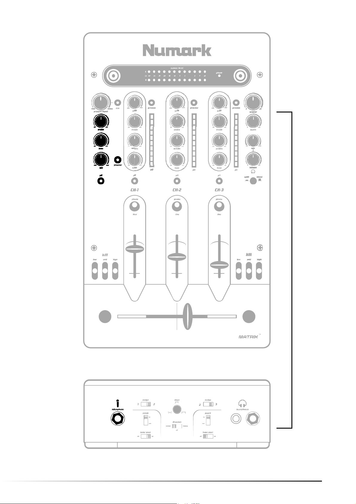
1. Microphone Controls
"Mic" (Microphone Trim)
This knob adjusts the volume of the main microphone. When turned all the way to the left, the volume is
at -8dB. When turned to the right, the volume is at 0dB. The Microphone Trim should be set at -8dB when
connecting and disconnecting a microphone from the Quarter-Inch "Microphone" Input on the front panel
of the mixer
"Treble" (Microphone High EQ)
This knob adjusts the high-tone input sound of the microphone (1kHz). The center position for this control
is flat (0dB.) Turning this knob to the right increases the high-tone input sound of the microphone (to
+10dB at 1kHz.) Turning this knob to the left decreases the high-tone input sound of the microphone (to
-30dB at 1kHz.)
"Bass" (Microphone Low EQ)
This knob adjusts the low-tone input sound of the microphone (70Hz). The center position for this control
is flat (0dB.) Turning this knob to the right increases the low-tone input sound of the microphone (to
+10dB at 70Hz.) Turning this knob to the left decreases the low-tone input sound of the microphone (to
-30dB at 70Hz.)
"Microphone" (Quarter Inch Microphone Input)
One microphone can be connected to this Quarter Inch output terminal. The Microphone Trim should
always be at its lowest setting while connecting and disconnecting a microphone to prevent damage to
the mixer and/or your audience.
"Process" (Microphone FX Processing)
See Section 8 "Effects Processing Controls."
"PFL" (Microphone Pre Fade Level Cueing)
See Section 4 "Cueing Controls."
PAGE 5 MICROPHONE CONTROLS
Page 7
SECTION 1
PAGE 6MICROPHONE CONTROLS
Page 8

CONTROLS
2. Primary Mixing Input Controls for CH-1 to CH-3
"Gain" (Input Level Trim)
This rotary control adjusts the input signal levels of the inputs. Turning the knob completely to the right
(clockwise) increases the level to +8dB. Turning the knob completely to the left (counter clockwise)
decreases the level to -8dB.
"Process" (Input FX Processing)
See Section 8 "Effects Processing Controls."
"Treble" (Input Level High EQ)
This rotary control adjusts the high-tone sound of the inputs. Turning the knob completely to the right
increases the level (to +10dB at 15kHz.) Turning the knob completely to the left decreases the level (to
-28dB at 15kHz.)
"Middle" (Input Level Midrange EQ)
This rotary control adjusts the mid-tone sound of the inputs. Turning the knob completely to the right
increases the level (to +12dB at 1kHz.) Turning the knob completely to the left decreases the level (to
-32dB at 1kHz.)
"Bass" (Input Level Low EQ)
This rotary control adjusts the low-tone sound of the inputs. Turning the knob completely to the right
increases the level (to +12dB at 40Hz.) Turning the knob completely to the left decreases the level (to
-32dB at 40Hz.)
"PFL" (Input Level Meter and Cue Button)
These meters display the peak levels of the inputs. You can use the "Gain" and EQ controls to match the
levels of input signals while Cueing.
For additional information on Cueing, see Section 4 "Cueing Controls."
"Phono/Line Switch" (Input Selector Switch)
These two-position toggles select what input source is engaged among the connected units (see Section 9
"Inputs and Outputs" for details on connecting sources.)
CH-1, CH-2 and CH-3 switch between a line level input (typically a CD player) and a Phono Level Input
(Turntable.)
These toggles can be rotated to suit your mixing preferences by removing the top Mixer Panel. See
Section 10 "Customizing and Servicing Your Mixer" for details.
Input Level Faders
These slide faders adjust the level for CH-1, CH-2 or CH-3 respectively.
PAGE 7 PRIMARY MIXING INPUT CONTROLS
Page 9

SECTION 2
PAGE 8PRIMARY MIXING INPUT CONTROLS
Page 10

CONTROLS
3. Meters and Lighting
"Master Level" (Master Level Meter)
This meter displays the stereo output levels of the master signal. The display ranges from -40dB to
+10dB.
Dual BNC Style Light Connectors
Two BNC style lights can be connected simultaneously to these 12V receptacles.
4. Cueing Controls
"Volume" (Headphone Level)
This rotary control adjusts the levels of the headphones connected to the front panel input. Turning the
knob completely to the right increases the level and turning the knob completely to the left decreases the
level.
"Split/Blend" (Master/Split Style Headphone Cueing Switch)
The split cueing mode is engaged by depressing the button into the low position. The split mode means
that any selected source (CH-1 to CH-3 and Mic) will be sent to the left channel of the headphones and
the master output is sent to the right. If the blend cueing mode is engaged (the button will be in the up
position) then the cued or master source (dependent on "Mix") will be heard in both the left and right
channels of the headphones.
"Mix" (Master/Cue Blend Control)
This control blends between the cued source(s) and the master output. At the center position an even mix
of both the master output and the cued source are monitored. Turning the knob completely to the right
selects only the master output and turning the knob completely to the left monitors only the cued
source(s.)
"Headphones" (Quarter Inch and Eighth Inch Headphone Output Terminals)
Two headphones can be connected simultaneously to these Quarter Inch and Eighth Inch output
terminals. The Volume should always be set at its lowest setting while connecting and disconnecting
headphones to prevent damage to headphones and/or your hearing.
"PFL" (CH-1, CH-2, CH-3 and Mic Cue Buttons)
CH-1, CH-2, CH-3 and the Microphone can be sent to the headphones one at a time or simultaneously for
cueing. When depressed, the PFL button illuminates yellow indicating that the source is being cued. Use
the "Mix" control to get a balance of the cued PFL source(s) and the master output in the headphones.
PAGE 9 METERS+ LIGHTING, CUEING CONTROLS
Page 11

SECTION 3
SECTION 4
METERS+ LIGHTING, CUEING CONTROLS PAGE 10
Page 12

CONTROLS
5. Master Output Controls
"Master" (Main Output Level Control)
This rotary control adjusts the main output levels for any equipment connected to the Master Output on
the rear panel (Section 9 "Inputs and Outputs"). Turning the knob completely to the right increases the
level to +10dB and turning the knob completely to the left mutes the signal.
"Booth" (Master/Split Style Headphone Cueing Switch)
This rotary control adjusts the auxiliary (AKA booth) output levels for any equipment connected to the
Booth Output on the rear panel (Section 9 "Inputs and Outputs"). Turning the knob completely to the
right increases the level to +10dB and turning the knob completely to the left decreases the level.
Blue Power LED
The blue power LED will illuminate when the mixer has been connected to a power source and switched to
the "on" position (See Section 9 "Inputs and Outputs.")
6. Crossfader Controls
Crossfader with Tracking Light System
This slide fader blends between the assigned inputs set by the "Assign" switches on the front Panel. Its
action can be fine-tuned using the "Slope" control or it can be reversed or deactivated by the "Direction"
switch. A red light glows on either the right, left or both sides for the Crossfader indicating only the
position of the Crossfader, not the amount of signal being sent to the master output.
"Slope" (Crossfader Curve Style Control)
The position of this knob determines where the startup level of the assigned channel (see "Assign"
switches) will lie on the Crossfader. When turned to the left, the Crossfader will gradually fade the
assigned channel in to the master output signal as it is engaged. When it is turned all the way to the
right, a very sharp fade of the assigned channel will occur immediately when the fader is engaged. The
center position is a mix of each of these actions.
"Assign" (1/2 switch and 2/3 switch)
The position of these switches determines which input channel is assigned to the Crossfader. The left
switch assigns either Channel 1 (left switch setting) or Channel 2 (right switch setting) to the left side of
the Crossfader. The right switch assigns either Channel 2 (left switch setting) or Channel 3 (right switch
setting) to the right side of the Crossfader.
"Direction" (Crossfader Reverse and Deactivation Control)
The position of this switch can reverse or deactivate the assigned channels of the Crossfader. In the left
switch setting, the channels are assigned according to the "assign" switches. In the right switch setting,
the channels are reversed from their settings of the "assign" switches. In the center position, the
Crossfader is deactivated.
PAGE 11 MASTER OUTPUT, CROSSFADER CONTROLS
Page 13

SECTION 5
SECTION 6
MASTER OUTPUT, CROSSFADER CONTROLS PAGE 12
Page 14

CONTROLS
7. Special Crossfader Related Features
"Kill" (Flash/Eliminate EQ Toggles)
These toggles eliminate the signal level for their respective frequency (low range, midrange and high.) In
the upward position, the switch will lock in position. In the downward position, the switch eliminates the
frequency until it is released. The left set of kill switches is used to control the sound of the input assigned
to the left side of the Crossfader. The right set of kill switches is used to control the sound of the input
assigned to the right side of the Crossfader.
Punch In/Out Transform Buttons
The punch buttons are used to instantly switch or eliminate the output of the mixer depending on the
Crossfader position. See "Punch" In/Out Switches for details on the settings and action of this control.
"Punch" (Punch In/Out switches)
The position of these switches determines whether the output sound will be eliminated or replaced with
the output assigned to the opposite channel. When the switch is in the upward position and the Punch
button is held then the output will be replaced with the signal assigned to the opposite to the mixer until
the button is released. This Punch "In" function will only swap the output signals when the Crossfader is
either completely to the left or completely to the right. When the position of the In/Out switch is in the
downward position then pressing the punch button will eliminate the output for that side until the button
is released. The Punch "Out" function works independently of the Crossfader position.
"Fader Start" (Fader Start On/Off switches)
When engaged the fader start can be used to instantly start a fader-start compatible device (See "Inputs
and Outputs" Section 9) by moving the Crossfader away from the endpoints. The behavior of this control
is largely dependent on the settings of your fader start compatible device.
NOTE: If the Fader Start function is on, then the Punch "In" Function may be deactivated depending on
the Fader Start mode that is selected on your compatible device. Consult your connected Fader Start
device manual for details on how this function interacts with the connected device.
8. Effects Processing Controls
"Process" (FX Processing Switch)
When engaged, this button illuminates red in color and routes the signal for that channel (CH1, CH2, CH3
or Microphone) to the Send Output on the Rear of the Mixer (See "Inputs and Outputs" Section 9.) When
processing a signal on more than one channel (CH1 and CH2 for example) then the signals will be blended
together because they are both being routed to the same destination via the Send Output. For optimum
performance, it is recommended that only one channel be processed at a time.
"Process Blend" (FX/Master Signal Blend)
This rotary control continuously blends the master output signal and the effect. Turning the knob
completely to the right maximizes only the return signal from the effects processor and turning the knob
completely to the left maximizes only the master output signal. In the center position a 50% blend of the
master and the return signal are sent to the master output. Use the "cue" button to preview the blend of
FX and the master signal in the headphones.
PAGE 13 SPECIAL CROSSFADER RELATED FEATURES, EFFECTS
Page 15

SECTION 8
SPECIAL CROSSFADER RELATED FEATURES, EFFECTS
SECTION 7
PAGE 14
Page 16

CONTROLS
9. Inputs and Outputs
CH-1, CH-2 and CH-3 Phono/Line Stereo Inputs
Each channel has a selectable phono level input (phonograph level/line level) and a line level input. The
line level input is used to connect CD players and other line level devices. When connecting a turntable to
the phono input, the switch must be set to "PHONO" instead of "AUX." When this switch is set to "AUX"
you can connect a line level device to the mixer (CD player, etc.) Please note that many turntables need
to be grounded to the mixer with a ground wire to prevent hum and excessive noise (see "GND.") It is
also recommended that the mixer be turned off before connecting and disconnecting any sources to the
inputs of the mixer.
"Effects" (Stereo Send Output/Stereo Return Input)
The RCA "Send" output will send a stereo Post Fader Level Signal (a signal that is effected by the
Equalizer) to the "Input" of an external effects processor (not included.) The RCA "Return" output is for
receiving a processed stereo signal from the connected external effects processor. These outputs are to be
used in conjunction with the "Process" and "Process Blend Controls" (See Section 8 "Effects Processing
Controls.")
"PFL Presend" (Stereo Pre Fade Level Output)
The RCA "PFL Presend" output will send a stereo Pre Fader Level Signal (a signal that is unaffected by the
Equalizer) to the "Input" of an external effects processor (not included.) The RCA "Return" output can
then be connected to receive a processed pre fader stereo signal from the connected external effects
processor. These outputs are also to be used in conjunction with the "Process" and "Process Blend
Controls" (See Section 8 "Effects Processing Controls.")
"Master" (Main Stereo Output)
This RCA output is for connecting an external monitoring device such as a PA system, powered monitors
or a home stereo. The level of the master stereo output signal increases as the "master" volume control is
increased.
"Booth" (Auxiliary Stereo Output)
This RCA output is for connecting a secondary external monitoring device such as a booth monitor or
second stereo output. The level of the booth output signal will increase as the "Booth" volume control is
increased.
"Rec" (Recording Level Stereo Output)
This RCA output is for connecting an external recording device such as a CD Recorder, MD Recorder or a
Tape Deck. The level of this signal is not affected by "master" volume or "booth" adjustments but is
affected by all other controls.
"GND" (Grounding Lug)
This screw connector should be used to secure any devices connected to the mixer that need to be
grounded. Most turntables that are connected to the mixer will need to have a ground wire that is
designed to connect to the mixer to eliminate hum and noise.
PAGE 15 INPUTS AND OUTPUTS
Page 17

"Balance Output" (Balanced Quarter Inch Stereo Output)
These Quarter Inch outputs are for sending a balanced level signal to a PA system or recording device.
The level of the balanced output signal will also increase with the "master" volume control. These outputs
are durable and offer a better output signal than the "master" or "booth" outputs.
"Player A/B" (Fader Start Eighth Inch Terminals)
These two eighth inch terminals allow Fader/Remote Start Compatible devices (CD Players, Turntables,
etc) to be connected to the unit using eighth inch fader start cables (not included.) Any connected device
can then be remotely started using the Crossfader (Section 7 "Special Crossfader Related Features.)
"Fader Start" must be switched to the on position for this feature to work properly.
AC In and Power Switch
This mixer will only work with the power supply assembly that comes with the unit. Make sure that the
arrow on the multi-pin power connection is facing upward before inserting the power cable into the mixer
(See illustration below.) The mixer should be switched on after all devices are already connected to
prevent damage to your equipment. A Blue Power LED indicates that the unit has been switched on (See
Section 3 "Meters and Lighting.")
INPUTS AND OUTPUTS
PAGE 16
Page 18

CONTROLS
10. Customizing and Servicing Your Mixer
Replacing the Crossfader
This mixer features a replaceable Crossfader. The Crossfader can be
removed from the mixer by loosening the two screws at the endpoints of the fader (See illustrations at
right.) Follow the steps below for removing the top panel to have access to the Crossfader.
Customizing the Direction of the Input Selector Switches
This mixer features multi directional Input Switches that can be removed and rotated to one of eight
positions (See illustrations at right.) Each Input Selector Switch is secured to the mixer by two adjacent
screws. Be sure to make note of the current switch position and the new switch positions before rotating
the switches to prevent any uncertainty before re-securing the top panel. Follow the steps below for
removing the top panel to have access to the Input Selector Switches.
Removing the Top Panel
CAUTION!
BEFORE REPLACING ANY PARTS, IT IS EXTREMELY
IMPORTANT TO UNPLUG THE MIXER FROM ITS
POWER SOURCE.
1. Unplug the mixer and set it on a flat surface. 2. Remove the Four Fader Knobs.
3. Remove the four screws that secure the
top panel using a #2 Philips Screwdriver.
4. Carefully remove the top panel.
PAGE 17 CUSTOMIZING + SERVICING YOUR MIXER
Page 19
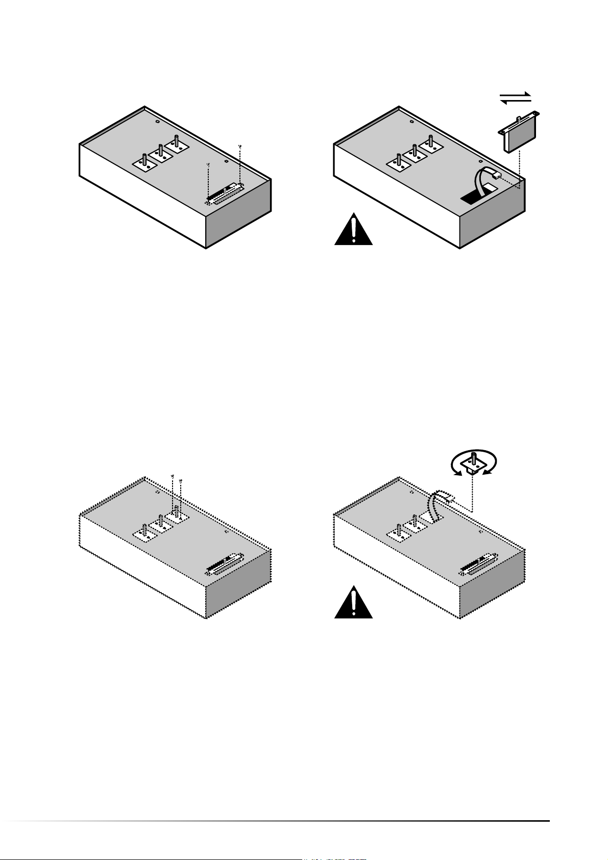
Replacing the Crossfader
1. After removing the top panel, remove the
two screws that secure the crossfader
using a #2 Philips Screwdriver.
Customizing the Direction of the Input Selector Switches
2. Carefully slide the crossfader out of the
mixer chassis, and unplug the harness
from the bottom of the part. Replace the
crossfader, refasten the two screws that
hold the crossfader in place.
3. Resecure the top panel, test the function,
and refasten the four screws that secure
the top panel.
1. After removing the top panel, remove the
two screws that secure the selector switch
you want to rotate using a #2 Philips
Screwdriver.
2. Carefully slide the switch out of the
mixer chassis, and unplug the harness
from the bottom of the part. Rotate and
replace the switch, refasten the two screws
that hold the switches in place.
3. Resecure the top panel, test the function,
and refasten the four screws that secure
the top panel.
PAGE 18CUSTOMIZING + SERVICING YOUR MIXER
Page 20

SPECIFICATIONS
Inputs:
Line: 10K ohm input impedance
80mV rms sensitivity for 1.22V output
Mic: 600 ohm input impedance unbalanced
0.85mV rms sensitivity for 1.22V output
57mV rms max input
Phono: 47Kohm input impedance
1.3mV rms sensitivity @ 1KHz for 1.22V output
Outputs:
Line: 9V rms max
Headphone: 0.5W into 47ohm
Distortion: less than 0.01%
Signal to Noise Ratio: (maximum output) JIS-A weighted
Line: Better than 92dB
Mic: Better than 82dB
Phono: Better than 85dB
Frequency response:
Line: 20Hz-20KHz +/-0.5dB
Mic: 20Hz-15KHz +/-0.5dB
Phono: +/-1dB except for controlled attenuation of -3dB
@ 20Hz to reduce rumble and feedback
Channel equalizer:
Bass: +12/-32dB @40Hz
Middle: +12/-32dB @1KHz
Treble: +10/-28dB @15KHz
Channel Kill:
Bass: Better than 80dB at 40Hz
Middle: Better than 80dB at 1KHz
Treble: Better than 80dB at 15KHz
Power consumption:
19.2 Watt typical
21.6 Watt with full headphone output
Dimensions:
220mm(W) by 370mm(D) by 90mm(H)
Weight: 4.8 kgs
PAGE 19 SPECIFICATIONS
Page 21

LIMITED PRODUCT WARRANTY
What is covered and for how long?
1. NUMARK INDUSTRIES LCC ("NUMARK") warrants to the original purchaser that NUMARK'S DJ mixers and amplifiers are free from
defects in material and workmanship under normal use and service for the period commencing upon the date of purchase from an
authorized NUMARK dealer and continuing for the following period of time after that date for (2) Years. The warranty is extended to (3)
Years with the completion of the warranty card provided that the warranty card is completed and returned within (30) days from the
date of purchase. All other NUMARK products are warranted for (1) Year including but not limited to CD players, CD Mix Stations,
turntables, preamplifiers, beatkeepers, equalizers, microphones, headphones, and all other accessories.
What is not covered? This Limited Warranty is conditioned upon proper use of the product by the purchaser.
2. This Limited Warranty does not cover: (a) defects or damage resulting from accident, misuse, abuse, neglect, unusual physical or
electrical stress, modification of any part of the product, or cosmetic damage; (b) equipment that has the serial number removed or
made illegible; (c) all plastic surfaces and other externally exposed parts that are scratched or damaged due to normal use; (d) defects
or damage from improper testing, operation, maintenance, installation, adjustment, or service of the mixers; (e) crossfaders.
3. What are NUMARK'S obligations? During the applicable warranty period, NUMARK will repair or replace, at NUMARK'S sole discretion,
without charge to the purchaser, any defective component part of the mixer. To obtain service under this Limited Warranty, purchaser
must first contact NUMARK and obtain a return authorization number ("RA#").
Purchaser must then return the mixer to NUMARK in an adequate container for shipping, accompanied by purchaser's sales receipt or
comparable proof of sale showing the date of purchase, the serial number of the product, and the seller's name and address. To obtain
an RA# and assistance on where to return the mixer, contact NUMARK customer service at 401-295 9000. Upon receipt, NUMARK will
repair or replace the defective products. NUMARK may, at NUMARK'S sole discretion, use rebuilt, reconditioned, or new parts or
components when repairing any product or replace a product with a rebuilt, reconditioned or new product. Repaired mixers will be
warranted for a period equal to the remainder of the original Limited Warranty on the original mixer or for (90) days, whichever is
longer. All replaced parts, components, boards and equipment become the property of NUMARK. If NUMARK determines that any mixer
is not covered by this Limited Warranty, purchaser must pay all parts, shipping, and labor charges for the repair or return of such mixer.
4. What are the limits on NUMARK'S liabilities?
THE WARRANTIES GIVEN IN THIS LIMITED WARRANTY, TOGETHER WITH ANY IMPLIED WARRANTIES COVERING NUMARK MIXERS,
INCLUDING WITHOUT LIMITATION ANY WARRANTIES OF MERCHANTABILITY OR FITNESS FOR A PARTICULAR PURPOSE, ARE LIMITED
TO THE DURATION OF THIS LIMITED WARRANTY. EXCEPT TO THE EXTENT PROHIBITED BY APPLICABLE LAW, NUMARK SHALL NOT BE
LIABLE FOR ANY SPECIAL, INCIDENTAL, CONSEQUENTIAL, INDIRECT OR SIMILAR DAMAGES, LOSS OF PROFITS, DAMAGES TO
PURCHASER'S PROPERTY, OR INJURY TO PURCHASER OR OTHERS ARISING OUT OF THE USE, MISUSE OR INABILITY TO USE ANY
NUMARK MIXER, BREACH OF WARRANTY, OR NEGLIGENCE, INCLUDING BUT NOT LIMITED TO NUMARK'S OWN NEGLIGENCE, EVEN IF
NUMARK OR ITS AGENT HAS BEEN ADVISED OF SUCH DAMAGES, OR FOR ANY CLAIM BROUGHT AGAINST PURCHASER BY ANY OTHER
PARTY. THIS LIMITED WARRANTY IS THE COMPLETE WARRANTY FOR NUMARK'S MIXERS, AND IS GIVEN IN LIEU OF ALL OTHER
EXPRESS WARRANTIES. THIS LIMITED WARRANTY SHALL NOT EXTEND TO ANYONE OTHER THAN THE ORIGINAL PURCHASER OF THIS
PRODUCT AND STATES PURCHASER'S EXCLUSIVE REMEDY. IF ANY PORTION OF THIS LIMITED WARRANTY IS ILLEGAL OR
UNENFORCEABLE BY REASON OF ANY LAW, SUCH PARTIAL ILLEGALITY OR UNENFORCEABILTY SHALL NOT AFFECT THE
ENFORCEABILITY OF THE REMAINDER OF THIS LIMITED WARRANTY WHICH PURCHASER ACKNOWLEDGES IS AND WILL ALWAYS BE
CONSTRUED TO BE LIMITED BY ITS TERMS OR AS LIMITED AS THE LAW PERMITS.
5. This Limited Warranty allocates risk of product failure between purchaser and NUMARK, and NUMARK'S product pricing reflects this
allocation of risk and the limitations of liability contained in this Limited Warranty. The agents, employees, distributors, and dealers of
NUMARK are not authorized to make modifications to this Limited Warranty, or ma ke additional warranties binding on NUMARK.
Accordingly, additional statements such as dealer advertising or presentation, whether oral or written, do not constitute warranties by
NUMARK and should not be relied upon.
6. How does state law apply to this warranty?
SOME STATES DO NOT ALLOW THE EXCLUSION OR LIMITATIONS OF INCIDENTAL OR CONSEQUENTIAL DAMAGES OR HOW LONG AN
IMPLIED WARRANTY LASTS, SO THE ABOVE LIMITATIONS OR EXCLUSIONS MAY NOT APPLY TO PURCHASER.
7. This Limited Warranty gives you specific legal rights. You may also have other rights, which vary from one jurisdiction to another.
RETURN INFORMATION (US ONLY)
a) A Return Authorization number must be obtained from Numark through the address or phone numbers
below.
b) A copy of the original sales receipt must also be included for the equipment to be repaired under
warranty.
c) The faulty equipment must be packed in its original packaging.
d) One additional outer layer of packaging must be included to ensure product safety. Failure to do so
may inadequately protect the equipment in transit and, therefore, jeopardize the customer's warranty.
e) Numark will not accept COD shipments and no call tags will be issued for merchandise return.
f) Numark will not return repaired merchandise to customers by priority service, unless by written request
at the customer's cost. Requests must be submitted in writing with merchandise returned.
g) The defective Numark equipment should be sent, FREIGHT PREPAID with Return Authorization number
clearly printed on the outer packaging and original sales receipt enclosed to:
NUMARK INDUSTRIES
Attention: Service Department
11 Helmsman Avenue
North Kingstown, RI 02852 USA
Phone: 1 (401) 295-9000
Fax: 1 (401) 295-5200 Web: www.numark.com
PAGE 20LIMITED PRODUCT WARRANTY
Page 22

Copyright Numark Industries, LLC 2001Matrix 3 Manual /English
 Loading...