


CONTENTS
Contents
Introduction........................................................... |
2 |
In the Package................................................................. |
2 |
Product Registration......................................................... |
2 |
Using This Manual........................................................ |
2 |
MIDI Controller Section Main Features......................... |
2 |
Audio Section Main Features........................................ |
2 |
Synthesizer Features....................................................... |
2 |
Quick Start Guide.................................................. |
3 |
Conventions used in this Manual.................................... |
3 |
Connecting Up To equipment......................................... |
3 |
Stand Alone Operation.................................................... |
3 |
Playing the Synthesizer.................................................... |
3 |
Windows XP USB Driver Installation............................. |
4 |
MAC OS X USB Driver Installation................................. |
4 |
About ASIO on Windows XP........................................... |
4 |
About Core Audio on MAC OS X..................................... |
4 |
Selecting The X-Station as the Audio Device................. |
5 |
Selecting The X-Station as the Audio Device in Cubase. ........ |
5 |
The X-Station Control Panel........................................... |
5 |
About Latency.................................................................. |
5 |
Selecting The X-Station as the MIDI Device in Cubase.......... |
6 |
Selecting The X-Station as the Audio Device in LOGIC.. ........ 6 |
|
Selecting The X-Station as the Audio Device in Reason.. ........ 7 |
|
Selecting The X-Station as the MIDI Device in Reason.. ........ 7 |
|
Controlling a VST Plug-In or Reason Instrument........................ |
7 |
Factory Supplied Templates........................................... |
7 |
Using The Programmable Template Controls................ |
8 |
Sending A Snapshot Of The Controls............................ |
10 |
Selecting A Sound On External MIDI Devices.............. |
10 |
Changing The Action Of The Pitch / Mod Joystick......... |
10 |
Audio Connection And Setup......................................... |
10 |
Setting Up The Microphone Or Instrument Inputs......... |
10 |
Monitoring...................................................................... |
10 |
Recording And Listening................................................ |
10 |
Recording And Listening With Effects............................ |
11 |
MIDI Tutorial......................................................... |
12 |
Introduction................................................................... |
12 |
How MIDI Ports Are Used............................................ |
12 |
MIDI Messages............................................................. |
12 |
Detailed Operation.............................................. |
15 |
Front Panel Layout....................................................... |
15 |
Modes And Menus....................................................... |
16 |
Using Menus................................................................ |
16 |
Entering Text................................................................ |
16 |
The Template Common Menu...................................... |
17 |
Template Edit Mode (Editing A Template).................... |
18 |
The Template Edit ‘CC’ Pages..................................... |
18 |
The Template Edit ‘NRPN’ & ‘RPN’ Pages.................. |
19 |
The Template Edit ‘MMC’ Pages.................................. |
19 |
The Template Edit ‘Note On/Off’ Pages....................... |
20 |
The Template Edit ‘SYSEX MESSAGE’ Pages............ |
20 |
The Template Edit ‘Program Change’ Pages............... |
21 |
Using The X / Y Touchpad........................................... |
21 |
Using The Footswitch Or Pedal................................... |
22 |
Saving A Template To Memory..................................... |
22 |
The Dual Multi Effects Processor................................. |
23 |
The Delay Effect........................................................... |
23 |
The Reverb Effect......................................................... |
24 |
The Chorus Effect......................................................... |
24 |
The Compressor........................................................... |
25 |
The Distortion Effect..................................................... |
26 |
The EQ Processor........................................................ |
26 |
Advanced Features............................................. |
27 |
Using The Transport Buttons....................................... |
27 |
The Global Mode Menu.............................................. |
27 |
Saving The Global Settings To Memory....................... |
29 |
Upgrading The Operating System From MIDI............. |
29 |
Synthesis Tutorial............................................... |
30 |
Elements Of A Sound.................................................. |
30 |
The Oscillators And Mixer............................................ |
31 |
The Filter....................................................................... |
32 |
Envelopes And Amplifier.............................................. |
33 |
LFOs............................................................................. |
35 |
Memories...................................................................... |
35 |
Summary...................................................................... |
35 |
The KS Synthesizer............................................. |
36 |
Introduction................................................................... |
36 |
Selecting KS Synth Patches........................................ |
36 |
Editing A Synth Patch (Sound)..................................... |
37 |
Saving A Synth Patch................................................... |
37 |
Using Menus................................................................ |
38 |
The Oscillator / Mixer Section..................................... |
38 |
The Filter Section......................................................... |
40 |
The LFOs Section........................................................ |
41 |
The Envelopes Section................................................ |
42 |
The Arpeggiator Section............................................... |
43 |
The Effects Section...................................................... |
44 |
The Oscillator Menu..................................................... |
44 |
The Mixer Menu........................................................... |
45 |
The Filter Menu............................................................ |
47 |
The LFO Menu............................................................. |
47 |
The Arpeggiator Menu.................................................. |
49 |
The Sync Menu............................................................ |
50 |
The Wheels Menu........................................................ |
51 |
The Aftertouch And Breath Menu................................. |
52 |
The Pan Menu.............................................................. |
53 |
The KS Synth Mode Global Menu................................ |
54 |
Routing MIDI To And From The KS Synthesizer.......... |
54 |
The KS Synth General Settings................................... |
55 |
Saving The KS Synth General Settings....................... |
55 |
Appendix.............................................................. |
56 |
Troubleshooting............................................................ |
56 |
Using The X-Station With Reason............................... |
57 |
Known Anomalies With Reason.................................. |
57 |
Preset Template Listings........................................... |
58-61 |
The KS Synth Patch Preset Listings............................ |
62 |
MIDI Implementation Chart........................................... |
64 |
Safety CE Notices And Approvals................................ |
65 |
• 1 •

INTRODUCTION
Using This Manual - Main Features - Conventions Used
Thank you for purchasing the X-Station controller keyboard and synthesizer. The X-Station is a state of the art product, it turns any computer into a complete, professional music & audio production workstation with hardware synthesizer, audio & MIDI interface, control surface and effects processor – all in one package with USB, PSU or battery power!
When used with a computer running a MIDI / Audio sequencer package it will provide a superb, compact recording setup.
It may be used to control sequencers, popular software virtual instruments on a computer or traditional hardware instruments via either a USB connection or a standard MIDI interface. In addition to the control features it contains two audio pre-amplifiers together with a twin multieffects processor that allows the recording and replay of mono or stereo audio signals to and from a computer.
The front panel provides a wealth of programmable controls arranged in the format of a traditional synthesizer, each of which can be configured to suit the needs of the instrument to be controlled. Each control can be stored within a Template memory for instant recall at a later time.
The X-Station is equally at home in a live performance or studio situation where it can be used as a stand-alone synthesizer, MIDI controller keyboard and recording device. Its comprehensive range of controls may be used to dynamically alter any sound parameters precisely and in real time whilst simultaneously recording and replaying stereo audio data.
In the package
The X-Station package contains the following list of items.
•Main Keyboard X-Station Unit
•Power Supply
•User Manual
•USB Cable
•Set of Template Overlays
•X-Station Driver and Resources CD-ROM
When opening the package, please make sure all of the items above are present, if not then please contact your local dealer.
www.novationmusic.com - Product Registration
Please take the time to register your new Novation X-Station. Point your browser to www.novationmusic.com and complete the registration form. We advise that you visit www.novationmusic.com from time to time to check for feature upgrades along with the appropriate documentation.
Using This Manual
MIDI Controller Section Main Features
X-Station features a superb two, four or five octave semi-weighted velocity-sensitive keyboard with combined Pitch bend and Modulation joystick. The keyboard is transposable up or down across the entire MIDI note range and can transmit Channel Aftertouch.
A programmable X/Y touch pad surface for simultaneous control of multiple parameters is provided.
MIDI or USB operation. USB and MIDI may be used simultaneously. A MIDI OUT port, a MIDI IN Port, a Foot pedal input socket and a
Footswitch input socket are available.
Power can be supplied by the USB port, Batteries or a 9V DC adapter.
A virtual synthesizer control panel layout comprising 28 buttons, 16 pots, 3 encoders and 9 sliders are assignable to each template. There is no need for template labels for control of most synthesizers
Any front panel control may be configured to transmit on any MIDI channel, to any destination utilising the comprehensive MIDI specification. Available options include Controller numbers, NRPNs, RPNS,
Bank Change, Program Change and definable System Exclusive
Strings. System Exclusive strings may be up to 20 bytes long. Control data may be inserted anywhere within the System Exclusive message.
40 Template editable memories are available. Each Template contains definitions for all front panel controls. Templates may be individually named for easy reference and saved to/from an external sequencer via MIDI Sysex bulk dumps
Audio Section Main Features
Two Novation high precision, low noise high bandwidth audio pre-ampli- fiers with phantom power and over 70 dB headroom deliver a warm, clear signal typical of Novation's commitment to sonic excellence.
Complete multi-effects processors are available per input channel featuring simultaneous Reverb / Chorus-Phaser / Delay / Compressor /
Distortion and EQ.
Integrated USB low latency Audio and MIDI - Requires just a single
USB connection a computer.
High power independent headphone output with separate stereo converter for zero latency monitoring of input signal with or without effects
44.1 / 48 Khz 24 bit simultaneous 2 channel Audio input and output operation
Driver software included to run on Windows XP or MAC OSX.
Synthesizer Features
This manual consists of seven sections; Introduction, Quick Start Guide, MIDI Tutorial, Detailed Operation, Advanced Features, Synthesis Tutorial and The KS Synthesizer. For easy reference, the section name is printed at the top of each page. An Appendix is also provided containing reference data.
It is assumed that the reader already has a basic knowledge of MIDI in order to configure user Templates. Those with limited MIDI experience may find the MIDI Tutorial useful. Although very little MIDI knowledge is required to use the the X-Station with the factory programmed Templates.
It is recommended that this manual is read in sequence chapter by chapter.
The main features of both its MIDI controller capability and Audio operation are listed below.
The X-Station includes a 3-oscillator virtual analog synthesizer model based on the renowned Novation KS-series and is 8-voice polyphonic.
The extensive control interface provides instant access to most parameters, making sound creation fast and intuitive. The synthesizer is totally integrated with computer recording setups: The stereo audio output is sent straight through the USB cable onto the track into any ASIO-com- patible sequencer.
There are 200 excellent factory sound programs which have been carefully crafted to cover most styles of music and programs can be easily imported and exported into a sysex librarian.
• 2 •

QUICK START GUIDE
Connecting Equipment - Stand Alone Operation - Playing the Synthesizer
Conventions Used In This Manual
The word ‘Template’ refers to a collection of knobs, encoders and button settings and the function of the footswitch, pedal and X-Y touchpad.
Each Template is numbered from 1 to 40 and can be saved in the X-
Station’s non-volatile memory.
The word ‘Template Label’ refers to a coloured or blank ‘overlay’ which sits neatly in the synthesizer control panel area.
The word ‘Preset’ refers to a Template configured at the factory to showcase some of the powerful control possibilities. Preset Templates may be over-written by new settings.
The word ‘Control’ refers to any of the front panel knobs, assignable buttons, encoders, footswitch, foot pedal, joystick or the X-Y touchpad.
Within a single Template. Each control may be individually configured to transmit various types of MIDI information addressed on any combination of the MIDI OUT / USB ports.
The word ‘Setting’ refers to any parameter which is edited from within a menu.
The word ‘Synth Patch’ refers to a synthesizer memory which is accessed while the X-Station is operating in the synthesizer mode.
Text in CAPITALS refers to a front panel Control or legend (even though the name of the Control may actually be in lower case on the front panel). It could be a knob, button, slider or rotary encoder.
Connecting Up To Equipment
In order to record or replay Audio or MIDI data it will be necessary to connect the X-Station to a desktop or laptop computer with the appropriate MIDI and Audio recoding software installed.
When connected to a computer, power will be supplied directly from the USB cable connection and it will not usually be necessary to fit batteries or plug into an external PSU.
Laptop Operation
When using a USB connection to power the X-Station from a Laptop computer, the X-Station may not power up successfully. This is due to the X-Station not being able to draw enough power from the Laptop computer.
The X-station requires approx 350mA of power to operate dependent on various conditions. Switching on the phantom power, turning up the monitor volume in the headphones and charging the batteries will add to the power consumption. Although the USB specification dictates that all computers should be able to supply 500mA of current which is ample, some Laptops are not able to supply as much as this.
The solution is to either :
1)Power the X-Station from the supplied AC:DC power adapter.
2)Insert Dry or rechargeable batteries (recommended) .
3)Connect the X-Station to a powered USB Hub.
The X-Station will run on all types of ‘C’ size dry or re-chargeable cells.
Nicad batteries are rechargeable and will last approx 6 hours.
Alkaline batteries are normal high power dry cells. They are not rechargeable and will last approx 12 hours.
Duracell batteries are extra high power, long life dry cells. They are not rechargeable and will last approx 24 hours.
The X-Station will automatically sense the battery type and calculate charging rate depending on the condition of the battery.
Fitting Batteries
Turn the X-Station upside down and unclip the battery compartment using two fingers to push on the clips. Observe the connection diagram imprinted on the plastic casing for 6 x ‘C’ cells to the right of the battery cover. Fit the cells as shown in the diagram.
Power Operation
The X-Station may be configured to charge or not charge the batteries
(if rechargeable's have been fitted) from either the USB port, the external power supply or both. - See page 26 in the Global Menu Section for details.
Stand Alone Operation
The X-Station may be used as a stand alone synthesizer, MIDI controller and/or a stand alone 2 channel Audio Mixer / Pre-amp with effects processors. In this case it is not necessary to connect to a computer system.
Novation PSU 6 |
Powered Monitor Loudspeakers |
Guitar |
Microphone |
|||||
Power Supply |
|
|
|
|
|
|
|
|
|
|
|
|
|
|
|
|
|
|
|
|
|
|
|
|
|
|
|
|
|
|
|
|
|
|
|
|
|
|
|
|
|
|
|
|
|
|
|
|
|
|
|
|
|
|
|
|
|
|
|
|
|
|
|
|
|
|
|
|
|
|
|
|
|
- |
+ |
|
|
|
|
MIDI |
|
|
X |
- |
STATION 25 |
|||||||||||
|
|
|
|
|
|
Power in |
|
Sustain |
Expression |
|
|
|
|
|
|
|
|
|
|
|
|
|
||
|
|
|
|
|
|
|
9V DC |
USB |
pedal |
pedal |
out 2 |
out 1 |
in |
SPDiff out |
Headphones Output 2 Output 1 |
Input 2 |
Input 1 |
|||||||
|
|
|
|
|
|
|
|
|
|
|
|
|
|
|
|
|
|
|
|
|
|
|
|
|
|
|
|
|
|
|
|
|
|
|
|
|
|
|
|
|
|
|
|
|
|
|
|
|
|
|
|
|
|
|
|
|
|
|
|
|
|
|
|
|
|
|
|
|
|
|
|
|
|
|
|
|
|
|
|
|
|
|
|
|
|
|
|
|
|
|
|
|
|
|
|
|
|
|
|
|
|
|
|
|
|
|
|
|
|
|
|
|
|
|
|
|
|
|
|
|
|
|
|
|
STAND ALONE AUDIO SETUP
If powered loudspeakers are not available then the outputs must be connected to an amplifier which in turn will power non active loudspeakers. If batteries are fitted - See previous page, then it is not necessary to use the external power supply.
Playing the Synthesizer
In stand alone operation the synthesizer may be used for live performance. To activate the synthesizer, press the PLAY / SYNTH button
SYNTH
Novation PSU 6 |
|
|
|
Sound Modules |
||||||||||
Power Supply |
|
|
|
|
|
|
|
|
|
|
||||
|
|
|
|
|
|
|
|
|
|
|
|
|
|
|
|
|
|
|
|
|
|
|
|
|
|
|
|
|
|
|
|
|
|
|
|
|
|
|
|
|
|
|
|
|
|
|
|
|
|
|
|
|
|
|
|
|
|
|
|
|
|
|
|
|
|
|
|
|
|
|
|
|
|
|
|
|
- |
+ |
|
|
|
|
MIDI |
|
|
X |
- |
STATION 25 |
|||||||||||
|
|
|
|
|
|
Power in |
|
Sustain |
Expression |
|
|
|
|
|
|
|
|
|
|
|
|
|
||
|
|
|
|
|
|
|
9V DC |
USB |
pedal |
pedal |
out 2 |
out 1 |
in |
SPDiff out |
Headphones Output 2 Output 1 |
Input 2 |
Input 1 |
|||||||
|
|
|
|
|
|
|
|
|
|
|
|
|
|
|
|
|
|
|
|
|
|
|
|
|
|
|
|
|
|
|
|
|
|
|
|
|
|
|
|
|
|
|
|
|
|
|
|
|
|
|
|
|
|
|
|
|
|
|
|
|
|
|
|
|
|
|
|
|
|
|
|
|
|
|
|
|
|
|
|
|
|
|
|
|
|
|
|
|
|
|
|
|
|
|
|
|
|
|
|
|
|
|
|
|
|
|
|
|
|
|
|
|
|
|
|
|
|
|
|
|
|
|
|
|
STAND ALONE MIDI SETUP
External sound modules may be directly connected to the MIDI output sockets. If batteries are fitted, then it is not necessary to use the external power supply.
• 3 •
QUICK START GUIDE
Driver Installation - Windows XP and MAC OS X
USB Driver Software Installation |
MAC OS X Driver Software Installation |
In order to use all of the features of the X-Station it must be connected to a computer system using the supplied USB cable. The USB connector is located on the rear panel. Before it can communicate with the computer’s USB connection port, a special piece of software known as a ‘USB driver’ must be installed.
The USB driver software converts information arriving at the computer’s
USB port into the correct format for use by the software Audio and MIDI interface used by the computers operating system. Most music application software (Cubase, Logic, Cakewalk, Sonar, Digital Performer etc) use this software Audio and MIDI interface to communicate with external hardware devices such as the X-Station or other keyboards and sound modules.
The USB driver software is located on the supplied driver and resource
CD ROM and must be used with the Windows XP Operating System. If using a PC with a different operating systems such as Linux, Windows
95, 98SE or 2000 USB support will not be available.
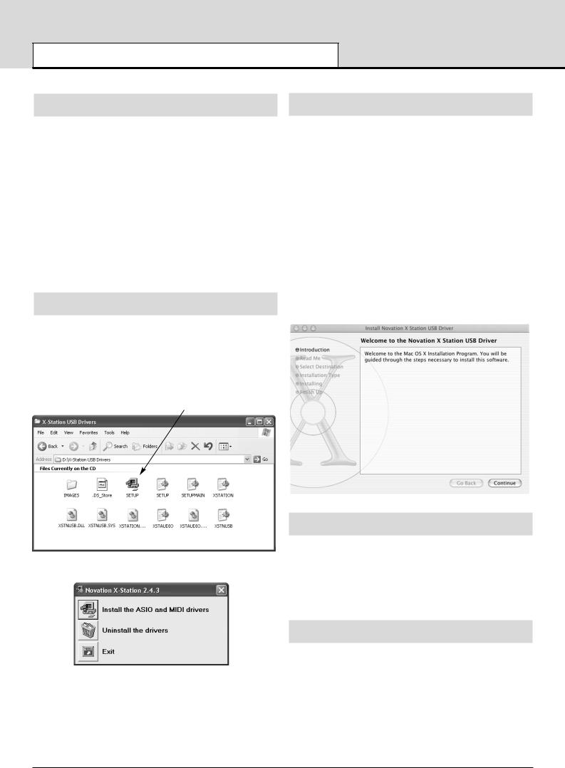
Windows XP USB Driver Software Installation
With the X-Station disconnected from the computer insert the X-Station driver and resource disc. If the computer does not automatically show an icon on the desktop for the CD, double click the 'my computer' icon. The X-Station driver disc is labeled as 'X-Station'. Double click this icon to show the contents of the disc.
Find and double click the directory 'X-Station USB Drivers'. Double click the icon 'Setup' for the setup application. Depending on the views set in Windows this icon may appear as ‘setup.exe’ in a list format.
The ASIO driver installation will begin.
With the X-Station disconnected from the computer, insert the CD labeled ‘X-Station USB Drivers Resources’ into the CD Rom drive.
Drag the X-Station.hqx file to the desktop and double click this icon to expand this. A file will appear on the desktop called 'X Station'. Open this folder to reveal the X-Station installer. Double click the 'X-Station
Installer' icon and follow the instructions that appear.
It will be necessary to enter the administrator password to complete the installation. At the end of the installation the computer will prompt to be rebooted. Accept this prompt.
Important Notice
The X-Station core audio driver cannot be loaded if the X-Station is turned on and connected to the computer when the computer is booting. Only connect the X-Station to the computer or turn on when the computer has booted fully.
The X-Station core audio driver is called 'Novation X-Station'. This should be selected as the core audio driver to be used from the appropriate Audio application, system preferences / sound or the application
'Audio MIDI setup'
About ASIO on Windows XP
Once the drivers are installed a special piece of software known as an ‘ASIO’ driver is available for use. This ASIO (Audio Stream Input Output) driver allows for very fast direct communication between the X-
Station and the music sequencer/audio recorder (such as Cubase,
LOGIC, Sonar, etc.) and keeps audio delays down to a minimum.
If using a Windows system, for optimum performance this ASIO driver must now be selected.
About Core Audio on MAC OS X
Click the icon 'install the ASIO and MIDI drivers' Follow the on screen prompts to install the X-Station drivers.
(if the X-Station or computer behaves erratically it may be necessary to power it from an external PSU or batteries - See page 3)
Similar to Windows systems, once the drivers are installed a special piece of software known as a ‘Core Audio driver’ is available for use.
This also allows for fast direct communication between the X-Station and the music sequencer/audio recorder (such as Cubase, LOGIC,
Sonar, etc.) and keeps audio delays down to a minimum.
If using a MAC system, for optimum performance the Core Audio driver must now be selected.
• 4 •

QUICK START GUIDE
Selecting the X-Station as the Audio Device
Selecting The X-Station as the Audio Device |
The X-Station Control Panel |
Open the music application such as Steinberg Cubase, Emagic Logic,
Cakewalk Sonar, MOTU Digital Performer or Propellerhead Reason and select the X-Station as the Audio and MIDI Device.
Certain audio settings may be changed by clicking on ‘Control Panel’ in the Device setup window. A panel will appear as illustrated below.
Selecting the X-Station as the Audio Device in Cubase SX or SX2
In Cubase SX or Cubase SX2 open the ‘Device setup’ window from the pull down menu under ‘Devices’
In the ‘Device setup’ window, click on ‘VST Multitrack’ A display similar to the following illustration will appear. There are drop down selection boxes titled ‘ASIO Driver’ and ‘Clock Source’ Click on the ‘ASIO Driver’ selection box and select ‘X-Station’.
Devices
The X-Station will be selected as the default device. No other device will be selectable.
Sample Rate
This will be set to 48kHz and cannot be altered. It confirms that the speed of data flowing backwards and forwards through the USB cable is 48kHz. This is not to be confused with Audio recording rates of 44.1 kHz and 48kHz.
Resolution
This will be set to 24bits and cannot be altered. It confirms that the size of data flowing backwards and forwards through the USB cable is up to
24bits. This is not to be confused with the Audio recording bit depth settings of 16bit or 24 bits.
Application Priority
This will be set to ‘High’. It will tell the Audio system to take priority over any other processes active in the PC. At ‘High’ priority it will allow an uninterrupted stream of audio to flow from the sequencer. Setting this to a lower priority will speed up other applications running on the computer but may cause clicks and glitches to occur in the audio stream
Use Dithering
Sound quality can be improved by adding a amount of ‘dither’. Leave this set to ‘checked’
About Latency
Latency is the amount of time it takes for the Audio Input Analogue signal to be converted to a digital signal, sent along the USB system, processed by the sequencer, then sent back along the USB system and converted back to a Analogue output signal. A latency time of anything more than approx 10mS will start to be noticeable.
• 5 •

QUICK START GUIDE
Selecting the X-Station in Cubase and LOGIC
The amount of latency can be set by changing ‘System Performance’ drop down box options. The higher the specification (speed of CPU and
RAM memory) of the computer being used, the lower the latency may be set. The choices are : Highspeed, Rapid, Fast, Normal and Relaxed. The default setting is ‘Medium’ however for the best performance the
‘Highspeed ‘ option should be selected.
After setting this option experiment with recording and replaying audio - see next few pages. If there are click and ‘pops’ appearing in the audio signal then try setting the performance to the next lowest setting.
Selecting the X-Station as the MIDI device Cubase SX or SX2
In order to receive MIDI information from the X-Station into Cubase, the
X-Station must be selected as a MIDI device.
In the project window click on the ‘In’ drop down box and select ‘X- Station’ (Emulated).
Now that the X-Station has been setup for Audio and MIDI turn to page
9 ‘Audio Connection and Setup’ for more information on using the Audio features. Refer to page 7 ‘Controlling a VST insturment’ for more information on using the MIDI control features.
Selecting the X-Station as the Audio device in LOGIC
In LOGIC open the ‘Audio Hardware & Drivers’ window from the pull down menu under ‘Audio as illustrated
In the ‘Audio Driver’ preferences window click on the small blue square box labeled ‘Core Audio’ and the window will open up similar to the illustration above. From the drop down box titled ‘Driver’ select
‘Novation X-Station’
NOTE : If just ‘X-Station’ is listed, turn the power off and then on again to the X-Station. The computer will then recognise that the unit is connected and will make available as a selection the correct ‘Novation X- Station’ driver.
Buffer Size Adjustment
The Core Audio driver temporarily stores input and output audio samples in buffers. Click on ‘I/O buffer size’ to adjust the buffer size. Larger buffer sizes provide ‘padding’ against system activities that may interrupt the audio stream causing click and pops. Setting a smaller buffer size will reduce audio latency. Experiment with this setting to optimise audio performance for the system.
Click on OK and the X-Station will now be selected as the default Audio device.
Selecting the X-Station as the MIDI device in LOGIC
In order to receive MIDI information from the X-Station into LOGIC, the
X-Station must be selected as a MIDI device. From the Main arrange page click on the ‘Windows’ drop down menu and select ‘Environment’.
A page similar to the illustration will appear. Click on the drop down arrow to select ‘MIDI Instrument’
Click on ‘New’ and select ‘Instrument’ from the drop down menu.
• 6 •

QUICK START GUIDE
Selecting the X-Station in LOGIC and Reason
The screen will display a new MIDI instrument Icon. Click the text at the top of the selection and enter ‘ X-Station’. An X-Station Icon appears.
example shown for Cubase by clicking on the ’ASIO control Panel’ button. Click the ‘X’ in the top right hand corner of the window to close the selection. The X-Station will now be selected as the default Audio device.
Selecting the X-Station as the MIDI device in Reason
Close the environment window. The X-Station may now be selected from the arrange page. Now that the X-Station has been setup for
Audio and MIDI turn to page 9 for more information on using the Audio features. Refer to ‘Controlling a VST insturment’ on this page for more information on using the MIDI control features.
Selecting the X-Station as the Audio device in REASON
From the Main Reason screen, open ‘Preferences’ window from the pull down menu under ‘Edit’
In the ‘Preferences’ window, click on the ‘Audio Card Driver’ drop down selection box and select ‘X-Station’ ASIO driver.
In order to receive MIDI information from the X-Station into Reason, the X-Station must be selected as a MIDI device. Open the
‘Preferences’ window as shown previously. In the ‘Page’ drop down selection click on the down arrow and select ‘MIDI’
Click the ‘X’ in the top right hand corner of the window to close the selection. The X-Station will now be selected as the default MIDI device.
Controlling a VST Plug-In Instrument or a Reason Instrument
The X-Station control panel is arranged in the format of a typical analogue subtractive synth design and Templates in the form of electronic memories that contain the specific control information for each instrument are preset in the X-Station.
Numerous software or hardware synthesizers may be played directly from the X-Station without the need for fitting a physical template overlay. For clarity, a few software synthesizers or real instrument emulations will benefit by placing one of the supplied labels over the front panel synthesizer area.
Factory Supplied Templates
Manufacturer |
Insturment |
Template Name |
Propellerheads |
Reason - Malstrom |
Malstrom |
Propellerheads |
Reason - ReDRUM |
Drum |
Propellerheads |
Reason - Mixer |
Mixer |
Native Instruments |
FM7 |
FM7 |
Native Instruments |
B4 |
B4 |
If precise Audio settings such as latency need to be adjusted, the X-
Station control panel may be selected and edited in a similar way to the
• 7 •
QUICK START GUIDE
Using The programmable Template Controls
In addition to the 5 preprinted labels there are a further 3 blanks which may be customised for any specific instrument. To fit a template label, simply place over the synthesizer control panel area.
.
ReMOTE audio template: blank
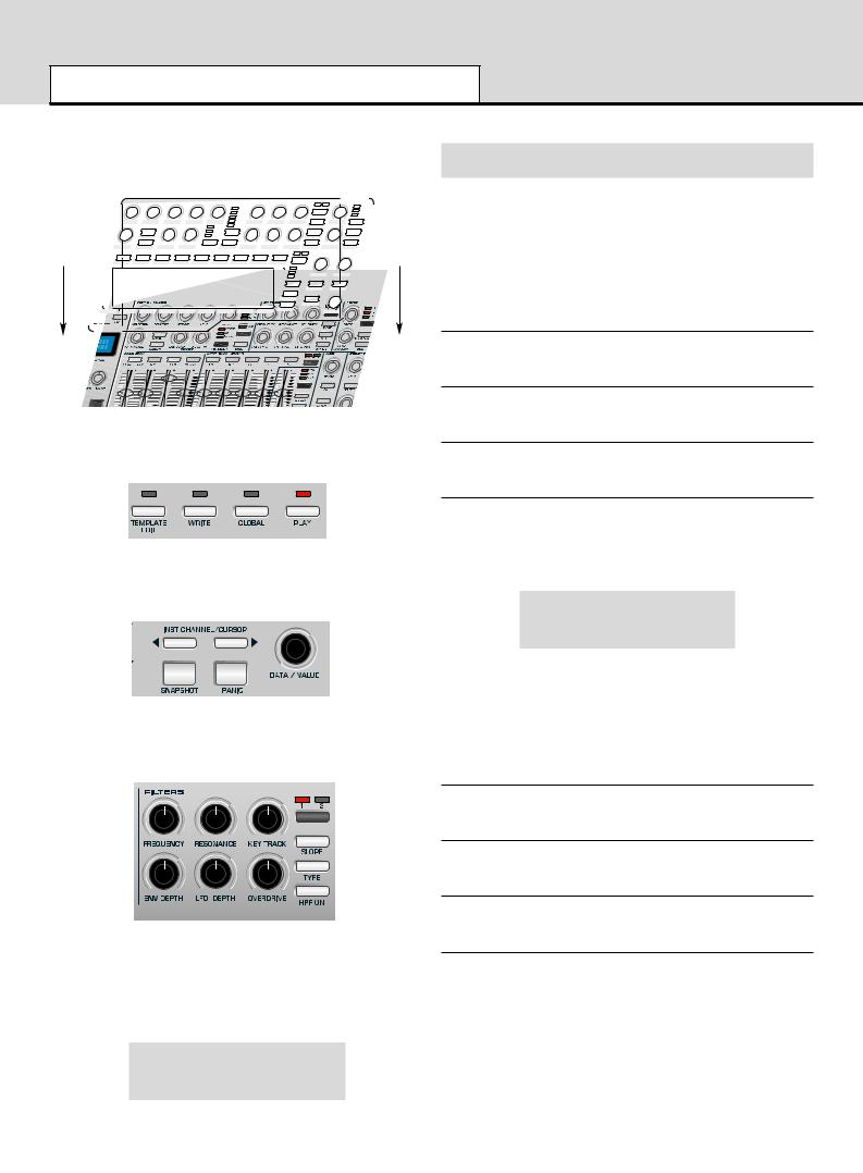
Check the front panel display area to see that PLAY mode is selected
(the LED above the button will be lit when in PLAY mode).
Rotate the encoder knob below the display to see the list of the electronic templates available. With each ‘click’ a new instrument electronic template will be selected. Continue to rotate until the desired instrument is selected.
Rotate the filter frequency control as shown in the illustration below notice how the real-time values of the controls are displayed.
The display will appear similar to illustration below and the filter frequency knob of the software instrument will rotate on the computers creen along with the corresponding change in sound.
Using The Programmable Template Controls
Every Template contains definitions of the type of MIDI information to be transmitted when any of the assignable encoders, knobs, sliders, buttons or X-Y touchpad are used. It is not mandatory that every control has to transmit MIDI information, so it is possible that controls in a
Template may be defined as ‘No Control’.
Data transmitted by a control is indicated on the bottom line of the display. When a control is moved, it will be one of the following :
Continuous Controller
This is indicated by CC followed by the controller number.
Non-Registered Parameter (NRPN)
This is indicated by NRPN. There is no controller number displayed.
Registered Parameter (RPN)
This is indicated by RPN. There is no controller number displayed.
MIDI Machine Control
The screen shows MMC. There is no controller number displayed.
The screen display when a control moved is slightly different for buttons using MMC :
Stop
1 MMC 1 U12
This is similar to the normal display shown when other types of MIDI information are transmitted, except that the top line displays the type of MMC command defined, while the bottom line at the left is the MMC number of the command defined for the button.
Only buttons can be assigned to send MMC. When MMC is used, there is no Control name used or displayed.
Note ON / Note OFF
The screen shows NOTE. There is no controller number displayed.
System Exclusive
The screen shows SYSEX. There is no controller number displayed.
Program Change
The screen shows PROGC. There is no controller number displayed.
Pitch Bend
The screen shows PBEND. There is no controller number displayed.
Filter Frequency
87 CC74 1 U12
• 8 •

QUICK START GUIDE
Sending Snapshots - Selecting External Sounds - Joystick - Audio Connection
Sending A Snapshot Of The Controls
It is possible to send a snapshot of current values to a connected MIDI device by pressing the SNAPSHOT button while in Play Mode.
The data values sent are the ones stored for each control in the
Template data, (except for where a control has been moved) since the
Template has been loaded. If a control has been moved, the new value represented by the position of the altered control is sent instead of the stored value.
Be aware that, when a snapshot is sent, the current position of a control might not bear any relation to the data value sent in the snapshot if that control has not been touched since the Template was selected.
For each control, the snapshot data is sent to the USB / MIDI port as assigned to the control in the within the template data. Any MMC functions assigned to buttons are not sent in a snapshot. It is possible for any Template to be set to automatically send a snapshot as soon as the
X-Station is placed into Play Mode. See page 15 for details.
Changing The Action Of The Pitch / Modulation Joystick
To suit different playing styles, the travel of the front to back movement of the modulation Joystick may be set to ‘Sprung’ or ‘Static’.
When shipped form the factory it is set to ‘Sprung’. Moving the joystick forward will always result in the stick returning to the forward position, therefore setting any data assigned to it back to an original value.
For example, if it is set to control the vibrato depth on a voice or oscillator, then letting go of the stick will remove any of the vibrato effect.
To set the stick to ‘Static’, turn the X-Station upside down. Push down on the plastic slider below the joystick assembly, and move the plastic switch to the opposite end of the cavity. To return to ‘Sprung’ mode, repeat the procedure in the opposite direction.
Setting to static allows the stick to be left in a position where modulation is applied without having to keep a finger pressed on the stick. This can be useful when the mod wheel is assigned to control the speed switch of an organ rotary speaker.
Audio Connection And Setup
Selecting A Sound On External MIDI Devices
In Play Mode, it is possible to select sounds on external MIDI devices directly by using the PROGRAM UP / DOWN buttons. When a
PROGRAM UP / DOWN button is pressed, the display shows :
MIDI Prog Chang:
104
and a Program Change message is immediately sent. If either PROGRAM UP / DOWN button is held down for about one second, the action auto-repeats, automatically incrementing or decrementing the value sent. Once the button is released, the display reverts back to showing the current Template’s name after about half a second.
Use the BANK UP / DOWN buttons to transmit a MIDI Bank Select message to a MIDI device. When pressed, the display shows :
MIDI Prog Bank:
05
and a Bank Select message is immediately sent. After about half a second the display reverts back to showing the current Template’s name.
Note that the X-Station always sends Bank Select messages using
CC32. This is used by most MIDI equipment, but some equipment may use CC0 messages. If this option appears not to change the Program bank on the MIDI device, it may be necessary to define another template control to transmit CC0 values. See pages 16-17 for details on assigning controller numbers to controls.
At this stage it is assumed that the X-Station is connected to a computer and both the computer and the X-Station are switched on.
Now that the software drivers have been installed, connect the X- Station to the other system devices. These could be as shown in the illustration.
Novation PSU 6 |
Powered Monitor Loudspeakers |
Guitar |
Microphone |
|||||
Power Supply |
|
|
|
|
|
|
|
|
|
|
|
|
|
|
|
|
|
|
|
|
|
|
|
|
|
|
|
|
|
|
|
|
|
|
|
|
|
|
|
|
|
|
|
|
|
|
|
|
|
|
|
|
|
|
|
|
|
|
|
|
|
|
|
|
- |
+ |
|
|
|
|
MIDI |
|
|
X |
- |
STATION 25 |
|||||||||||
|
|
|
|
|
|
Power in |
|
Sustain |
Expression |
|
|
|
|
|
|
|
|
|
|
|
|
|
||
|
|
|
|
|
|
|
9V DC |
USB |
pedal |
pedal |
out 2 |
out 1 |
in |
SPDiff out |
Headphones Output 2 Output 1 |
Input 2 |
Input 1 |
|||||||
|
|
|
|
|
|
|
|
|
|
|
|
|
|
|
|
|
|
|
|
|
|
|
|
|
|
|
|
|
|
|
|
|
|
|
|
|
|
|
|
|
|
|
|
|
|
|
|
|
|
|
|
|
|
|
|
|
|
|
|
|
|
|
|
|
|
|
|
|
|
|
|
|
|
|
|
|
|
|
|
|
|
|
|
|
|
|
|
|
|
|
|
|
|
|
|
|
|
|
|
|
|
|
|
|
|
|
|
|
|
|
|
|
|
|
|
|
|
|
|
|
|
|
|
|
|
|
|
|
|
|
|
|
|
|
|
|
|
|
|
|
|
|
|
|
|
|
|
|
|
This is a basic Audio connection. It will allow the recording of external signal sources such a those from a microphone or guitar and also allow the replay of Audio data from a sequencer to a pair of loudspeakers and headphones. (MIDI notes played from the keyboard and knob movements will also be sent to the sequencer).
If batteries are not fitted then an external power supply (Novation
PSU6) may need to be connected - See page 5. If this is the case, shut down the computer, turn off the X-Station and fit the batteries. Ensure the X-Station is still connected to the computer via the USB cable and switch both the X-Station and the computer on at the same time.
Connect any other devices such as sustain and expression pedals (if required) to the rear panel jacks. Finally, switch on the power to any other powered devices such as the loudspeakers.
Each of the two Audio Inputs provided can except a wide range of audio signals - from a low output level condenser microphone all the way up to a line level CD player. The line output jacks deliver an unbalanced audio signal which will directly drive an audio mixer, an audio power amplifier or powered loudspeakers.
• 9 •

QUICK START GUIDE
Setting Up Inputs - Monitoring - Recording And Listening
Setting Up The Microphone Or Instrument Inputs
Both of the audio inputs allow either 1/4” jack plugs or XLR type connectors to be plugged in and the input sensitivity of the high quality preamplifiers can be adjusted to accommodate different signal levels.
Adjusting the Input Gain
Select Input Channel 1 by pressing the INPUT button. With a microphone plugged into Channel 1, turn the GAIN knob until the GREEN
LED next to the GAIN knob is fully lit when speaking or singing into the
Microphone and the RED LED occasionally flashes.
This will set the gain of the preamplifier to the correct level for the Microphone such that it will not distort or be too quiet when recording.
Check that the Audio level that is being sent from the X-Station to the recording software is not too low or too high. To do this, look at the input meters within the recording software.
Adjust the LINE OUT LEVEL knob to ensure that the level on the input meters does not go too high (consult the recording software documentation for more information on this).
Using Phantom Power
If the Microphone being used is a ‘condenser’ type it will need to have a
DC voltage (normally 48V) sent to it before if will generate any audio output signal. Some microphones have their own power supply to do this but if not, the X-Station can supply the necessary voltage.
With the appropriate input channel selected (LED lit) press the PHANTOM button and the LED to the left of the button will light indicating that phantom power is being sent to the microphone on the selected channel.
WARNING : Some Ribbon, Dynamic and Electret type Microphones should NOT have phantom power delivered to them and if so may be damaged! - Check with the documentation supplied with the
Microphone so see if it requires phantom power.
Monitoring
The process whereby audio material already recorded into the audio sequencer is listened to by the artist or recording engineer while blended with any new material such as a voice or an instrument is known as
Monitoring.
In order that a Microphone used for recording a vocal does not pick up any of the already recorded sound tracks of, for example drums and bass back into the vocal track, headphones are usually used by the vocalist. A ‘mix’ is sent to the Headphones of the live Microphone sound with the previously recorded material.
In a typical setup a separate audio mixer would be required to mix the signal from the live Microphone with the one already recorded. Since the X-Station provides independent headphone level and monitor knobs an external audio mixer is not required.
Zero latency monitoring
The input signal from either microphone or instrument is converted to a digital signal and is sent to the computer via a USB connection. It then goes into the music software application and is sent back for listening.
Using the ASIO driver software installed earlier, the time delays this process causes are kept to a minimum. It may however be annoying to the artist when making a new recording since this slight delay is perceived as an ‘out of time’ feel, or as an echo if this delay time is long.
The X-Station has a zero latency monitoring feature whereby a knob is provided to balance the previously recorded material with the live sound to be recorded.
There is also a knob ‘LINE OUT LEVEL’ to control the level of the signal going to powered Loudspeakers. With control over the output level to the Loudspeakers, it is very quick to switch between listening back to a new recording (for example a new vocal take has been added) to reverting to a Headphones only monitoring situation for recording a further vocal.
Recording And Listening
Listening
Check that the Microphone(s), Headphones and Loudspeakers are
plugged in and setup as described on the previous page. If the session is
purely for listening then turn up the LINEOUT knob and press the PLAY button on the software music sequencer. Any audio information that has been previously recorded should be heard in the loudspeakers. Notice that the headphones level may also be individually controlled by the PHONES VOL knob.
Mono Recording
If the Microphone and Loudspeakers are in the same room turn the LINEOUT knob fully anti-clockwise to ensure no previously recorded audio information is being sent to the loudspeakers.
Rotate the MONITOR knob fully anti-clockwise to listen to the Microphone input signal only. Put on the Headphones and talk into the
Microphone. It should now be possible to hear the microphone in the
Headphones.
If not, check that the monitor button is pressed on the software music sequencers track (consult the music software documentation on how to do this) When recording a new track, in this example a vocal, press the record and play button (consult the music software documentation on how to do this) on the sequencer and begin to talk or sing into the microphone.
The balance between the previously recorded tracks and the new live vocal may be adjusted to suit by rotating the MONITOR input to output knob.
Using Channel 1 and with the BALANCE knob set fully anti-clockwise, the live vocal will be sent to the left output of the Headphones or
Loudspeakers. Rotate the BALANCE knob to position it anywhere in the stereo field. Once the recording is complete, the finished, updated recording can be played back and listened in either the Headphones or
Loudspeakers or both by adjusting the LINE OUT LEVEL and PHONES VOL knobs.
• 10 •
QUICK START GUIDE
Recording And Listening With Effects
Dual Mono Recording
If it is desired to record two different inputs simultaneously - for example a guitar and a vocal, repeat the setup process and set the input gain for both the microphone and the guitar independently. Use the INPUT button to switch between each input to set the signal level using the LED’s Begin recording and use the BALANCE knob to move the left to right position of either of the two inputs. Within the sequencer set one track to Input Channel 1 and the other track to Input Channel 2.
Stereo Recording
Plug in a Stereo source (such as a CD player) and press the STEREO button. Both input LED’s will light. Use the GAIN knob as previously described to set the appropriate input level.
The BALANCE knob behaves in a different way when recording a
Stereo device. Rotating it fully anti-clockwise will result in the signal being summed into a MONO signal. Rotating it fully clockwise will result in a WIDE Stereo signal As in the previous examples the balance between the previously recorded tracks and the new live stereo input may be adjusted to suit by rotating the MONITOR input to output knob.
ered as a very useful option when, for example, recording a voice the signal can be recorded 'dry' but the artist will be able to listen (monitor) his or her performance with effects applied.
Adding Reverb
In the effects section press the UP/DOWN buttons to select the Reverb effect - the corresponding LED will light. Adjust the LEVEL knob for the desired amount of Reverb effect. The effects processors are powerful multi effects type whereby one of each different effect may be applied simultaneously if desired
See section ‘ Detailed Operation - The Dual Effects Processor’ on page 21 for more information on audio control and using the effects processor on recordings.
Recording And Listening With Effects
Most modern software audio sequencers allow the input signal to be monitored with low latency but this is only a copy of whatever is plugged into the audio input(s).
An outstanding feature of the X-Station is the ability to record and / or monitor complete with effects, such as Reverb, without the need for an external hardware effects box or without the need to engage additional effects processors within the recording software.
This is particularly useful when recording vocals since the artist will normally prefer some amount of reverb in the headphones during a performance. It usually will help him/her to envisage a live situation with some ambience in the room.
There are three options with regard to monitoring and recording the effects:
1. Bypass
This option will disable the effects section and the computer system will record any audio data 'dry' - that is, an amplified version of the signal appearing at the audio inputs. Any monitoring of the signal by headphones or on the main left and right outputs will also be 'dry'
2. Listen - Record
This option will enable the effects section and the computer system will record any audio data 'wet' - that is, an amplified version of the signal appearing at the audio inputs together with any of the audio effects (such as reverb). Any monitoring of the signal by headphones or on the main left and right outputs will also be 'wet'
3. Listen - No Record (Listen wet and Record Dry)
This option will enable the effects section BUT the computer will record any audio data 'dry' - that is, an amplified version of the signal appearing at the audio inputs. Any monitoring of the signal by headphones or on the main left and right outputs will be 'wet'. This would be consid-
• 11 •

MIDI TUTORIAL
Introduction - MIDI Ports - MIDI Messages
Introduction
MIDI is an acronym for Musical Instrument Digital Interface. The MIDI standard was devised in the early 80’s as a means for allowing musical instruments to communicate with each other as well as with other devices such as sequencers and computers. Before the advent of MIDI, it was often very difficult (if not impossible) for instruments to effectively communicate with each other, especially if they had been made by different manufacturers. Nowadays, most types of electronic musical equipment are equipped with a MIDI interface fitted as standard, including synthesizers, drum machines, samplers, sequencers, computers and even some effects units.
The MIDI standard allows many different instruments to be controlled at once (say from a sequencer or a controller keyboard such as the X-
Station) using the same network of MIDI cables. Each instrument in the
MIDI chain is usually assigned its own unique MIDI channel and will only respond to information that it may receive on that particular channel. The MIDI standard allows for sixteen different channels to be assigned to the various instruments in a MIDI network. This means that it is normally possible to have up to sixteen instruments playing simultaneously within a MIDI system.
Some people may feel that being restricted to just sixteen MIDI channels might be a little limiting, especially if they are composing very complex pieces of music. However, most current sequencers, MIDI ports for computers and master keyboards offer a neat way around this problem.
They can offer several different MIDI outputs, each of which is treated as a separate MIDI system in its own right with its own set of sixteen MIDI channels. The X-Station may use any combination of its MIDI OUT & USB ports for this purpose.
How MIDI Ports Are Used
The X-Station has three MIDI ports, one labeled ‘In’ and two ‘Outs’.
Additionally, there is a USB port which acts in a manner similar to a combined MIDI IN / MIDI OUT. Each type of MIDI port has a specific purpose :
MIDI IN ports
These are used by the X-Station to receive incoming MIDI information. It is possible to configure the X-Station to immediately re-transmit this MIDI information to any of the X-Station MIDI Out ports or to the USB port. This is detailed on page 25. The X-Station can process incoming
MIDI from the MIDI IN port or the USB port simultaneously.
MIDI OUT Ports
These can transmit any MIDI information which might be generated by the X-Station. For example, if a note was played on the X-Station keyboard or one of the controls were moved on the front panel. This MIDI information is intelligently merged with any MIDI being re-transmitted after arriving at the MIDI IN / USB ports.
USB Port
This port is used to connect the X-Station to a computer that features a
USB port. It can be regarded as a special port that can send and receive MIDI information simultaneously. It is the most convenient way of connecting to a computer, avoiding the need to connect two sets of standard MIDI cables between the X-Station and a separate MIDI interface. The information which flows through the USB connection conforms to the same Message format as standard MIDI.
Since MIDI information flows in one direction only along a standard MIDI cable, it is not possible to have a MIDI In socket connected to another MIDI In socket. If this were done the MIDI network would simply not work! In fact, the only two routings allowed are MIDI Out to MIDI
In or MIDI Thru to MIDI In.
Keyboard Controllers such as the X-Station are used to generate MIDI data for controlling other instruments. Examples of other common MIDI controllers are drum percussion pads or footswitch controllers. Of course, the X-Station is capable of much more than just controller keyboard duties!
MIDI Messages
The X-Station is capable of transmitting various types of MIDI events.
These are as follows :
Note Messages
A note message is transmitted every time a key on the X-Station keyboard is pressed down or released. When a keyboard note is pressed down, the MIDI message also includes velocity information. This represents how hard the key was pressed down. This velocity value can be used to add dynamics to the sound, depending on how hard the note was played.
It is also possible to configure buttons on the front panel to transmit
Note messages such that a Note On message is sent when the button is pressed and the corresponding Note Off message sent when the button is released. This is detailed on page 18.
Control Change Messages
These messages are commonly used to alter synthesizer parameters by MIDI. In many of the Preset Templates, it is actually Control Change messages which are sent when the front panel controls are moved.
The MIDI specification allows for 128 different types of controller message. These are often referred to as Continuous Controllers (CC0 to CC127).
Some controllers are rigidly defined by the MIDI standard for specific functions. For example, CC1 is always used for the modulation wheel. Therefore, whenever the X-Stations modulation joystick is moved, it will transmit MIDI control change information using CC1. All makes of synthesizers will also use CC1 for modulation wheel data.
The Continuous Controller numbers rigidly defined include 0, 6, 32, 38, 96. 97, 98, 99, 100, 101 & 120 - 127. These are used for specialised specific purposes.
Many Control Change numbers have no set purpose within the MIDI specification. For example, whenever a Novation KS series Filter FRE-
QUENCY knob is moved, it will transmit using CC105. There is no guarantee however that other makes of synthesizer will use this control change number for the same purpose.
A CC MIDI message can contain a data value anywhere in the range 0 to 127.
Use of Control Change messages is detailed on page 16 .
Non-Registered Parameter Messages
Some synthesizers (such as the Novation KS series) actually have many more than 128 different parameters that can be transmitted by MIDI, but because the number of different types of control change message is limited to just 128, a more complicated arrangement for transmitting additional parameters is used. This arrangement is known as
Non-Registered Parameter Numbers (NRPNs for short).
NRPNs actually consist of three MIDI control change messages grouped together, rather than a single MIDI control change message which is normally used. The first two CC messages define the NRPN number of the message. CC98 is used to specify the least significant byte (LSB) of the NRPN number and CC99 is used to specify the most significant byte (MSB) of the NRPN number.
• 12 •

MIDI TUTORIAL
MIDI Messages
To calculate the MSB, divide the full NRPN number by 128. The remainder is the LSB value.
Once the LSB & MSB of the NRPN number have been sent, CC6 (known as Data Entry) immediately follows. This contains the actual data value to be sent in the NRPN.
As an example of how this works, consider sending a data value of 10 on NRPN number 260. The three grouped Continuous Controller messages would be :
CC98 (NRPN LSB) |
4 |
(260 modulus 128 = 4) |
CC99 (NRPN MSB) |
2 |
(260 / 128 = 2) |
CC6 (Data Entry) |
10 |
(data value) |
Many synthesizers do not use NRPNs. Consult your synthesizer manual for details of which NRPNs are recognised.
The use of NRPNs is detailed on page 17.
Registered Parameter Messages
These are known as RPNs and are similar in format to NRPN messages. CC100 is used to define the RPN LSB and CC101, the RPN
MSB (usually zero). As for NRPNs, CC6 contains the actual data value.
RPN numbers assigned by the MIDI specification are :
0Pitch Bend sensitivity
1Fine Tuning
2Coarse Tuning
3Tuning Program Select
4Tuning Bank Select
Many synthesizers do not use RPNs. Consult your synthesizer manual for details of which RPNs are recognised.
The use of RPNs is detailed on page 17.
Pitch Bend Messages
These messages are transmitted whenever the X-Station’s joystick is moved along the X axis. It is also possible to define the X - Y touchpad to transmit Pitch Bend.
As the name implies, pitch bend messages are used to move sounding notes up or down in pitch.
Aftertouch Messages
These messages are transmitted by some keyboards whenever already-held down keyboard notes are pushed further or wiggled. Aftertouch messages can be used to add extra expressiveness to a sound, for example introducing an extra vibrato effect.
The MIDI specification actually defines two different types of aftertouch message; Mono and Poly. The type transmitted by the X-Station is the
Mono type. This affects all sounding notes simultaneously.
Poly aftertouch includes information in the MIDI message about which keyboard note was used to trigger the aftertouch effect, allowing individual sounding notes to be affected. Poly aftertouch is actually very rarely found nowadays as only a very few synthesizers ever used it.
Program Change & Bank Select Messages
These messages are used to remotely select sounds on a synthesizer.
The MIDI Specification only allows a MIDI program change message to select one of 128 different sounds. When the MIDI specification was originally designed, this was rarely a problem since synthesizers seldom had more than 128 memories. Modern synthesizers such as the
Novation K-Station offer many more memories than this (the K-Station for example, actually has 400 memories divided into four ‘banks’ of 100 memories each), so it is often convenient to send a MIDI program change preceded by an additional MIDI message which specifies which
‘bank’ of sounds the following Program Change message will select from.
The Bank Select MIDI message used for this purpose is actually a MIDI
Control Change message. CC32 is the control change number used by
Novation and most manufacturers, but a few manufacturers may use CC0 instead. Consult the synthesizer manual for details on the Bank
Select Continuous Controller number used.
For example to select Program A100 on the Novation Supernova, the following MIDI messages would be needed :
CC32 |
5 (5 selects Program Bank A on the Supernova) |
Prog Change |
100 |
Synthesizers which implement Bank Select usually require that the appropriate Bank Select message is sent before a following Program Change message. Synthesizers not implementing Bank Select need only receive a Program Change message.
Warning : Many synthesizers will only accept a Program Change message if a Bank Select message has been received first !
Bank Select Messages may be sent from the X-Station by either using the DATA / VALUE encoder from from within Play Mode (CC32 is always sent) or by defining a control within a Template to transmit CC0 or CC32 as appropriate.
Program Change messages may be sent from the X-Station by either using the PROG / PAGE UP / DOWN buttons from within Play Mode or by defining a control within a Template to transmit Program Change.
Channel Messages
All of the different types of MIDI messages outlined so far include information detailing which MIDI channel was used when the message was transmitted. MIDI channel messages will only affect receiving devices using the same MIDI channel. For example, a Pitch Bend message sent using MIDI channel 1 would have no effect at all if it were received on a synthesizer set to respond on MIDI channel 2.
Some MIDI messages do not include any MIDI channel information defined in them. Some examples of these are :
System Exclusive Messages
This is special type of MIDI message, often referred to as ‘Sysex’.
System Exclusive messages can actually contain any type of data, depending what the synthesizer manufacturer decides to put in it! The only constraint with system exclusive messages is that they always contain certain header information which is exclusively used by the manufacturer (and usually the relevant synth model as well). What this effectively means is that a MIDI device will only accept a system exclusive message designed especially for it. For example, If the Novation K-Station should receive a system exclusive message transmitted by a different make of synthesizer, the message would simply be ignored.
Similarly, other makes of synthesizer will ignore any system exclusive messages originally sent by a Novation K-Station.
Unlike other types of MIDI message, System Exclusive messages do not have a fixed length. The MIDI specification allows any number of data bytes (each with a value between 0 to 127) between a Sysex Start byte and a Sysex End byte. The first data bytes in a Sysex message always contain the manufacturer ID. This is unique to each Synthesizer manufacturer.
Some manufacturers (such as Yamaha) employ short Sysex messages for sound editing purposes rather than using Control Change messages. The X-Station can send short System Exclusive messages containing up to 20 bytes (including the manufacturer ID). See page 18 for details.
The X-Station employs system exclusive messages for two distinct purposes. Firstly, they can be used to back up all of the X-Station memories and global data. This feature is extremely useful in building up a Template library or a Synth program library on a computer or for making a safety copy of data in case the worst should happen. Data backup is discussed in detail on Page 25 in the Advanced Features chapter.
• 13 •

MIDI TUTORIAL
MIDI Messages
Secondly, Novation also use system exclusive messages to enable an
X-Station to update its entire operating system via MIDI. The latest operating system for the X-Station is always available at the Novation web site. From there, it can be downloaded and installed with a proprietary installation utility. See page 27 for details.
MIDI Machine Control (MMC) Messages
These are are a range of messages designed to communicate with sequencers and recording devices. In reality, MMC commands are actually specialised forms of System Exclusive messages (termed
‘Universal’) which are designed to be recognised by any manufacturer supporting MMC.
When MMC commands are assigned to X-Station controls, only the
MMC command need be specified. The remainder of the MMC Universal System Exclusive message is automatically constructed by the X-Station. See page 17 for details on assigning MMC.
A MIDI Implementation Chart provides a concise way of telling at a glance which MIDI messages an instrument will transmit and respond to. A MIDI Implementation Chart for the X-Station can be found on page
57.
• 14 •

DETAILED OPERATION |
|
|
|
|
|
|
|
|
|
|
|
|
|
|
|
|
|
|
|
|||||||
|
|
|
|
|
|
|
|
|
|
|
|
|
|
|
|
|
|
|
|
Front Panel Layout |
||||||
1 |
|
|
|
|
|
2 |
|
|
|
|
|
|
3 |
4 |
|
|
|
|
|
5 |
|
|
|
|
|
6 |
|
|
|
|
|
|
|
|
|
OSCS - MIXER |
|
|
|
|
|
|
FILTERS |
|
|
|
|
|
LFOS |
|
|||
|
Input 1 |
|
|
|
|
|
|
|
|
|
|
|
|
|
|
Osc 1 |
|
|
|
|
|
|
1 |
2 |
|
1 |
|
Input 2 |
|
|
|
|
|
|
|
|
|
|
|
|
|
|
|
|
|
|
|
|
|
|
|
2 |
|
|
INPUT |
STEREO |
|
|
|
|
|
|
|
|
|
|
|
|
Osc 2 |
|
|
|
|
|
|
|
|
|
||
|
|
|
|
|
|
|
|
|
|
|
|
|
|
|
|
|
|
|
|
|
|
|
3 |
|||
|
|
|
|
|
|
|
|
|
|
|
|
|
|
Osc 3 |
|
|
|
|
|
|
|
|
|
|||
|
|
|
|
|
|
|
|
|
|
|
|
|
|
|
|
|
|
|
|
|
|
|
|
|
|
|
AUDIO IN |
EFFECTS |
|
|
TEMPLATE |
TEMPLATE |
WRITE |
GLOBAL |
PLAY |
|
|
|
|
|
|
Noise |
|
|
|
|
|
KEY TRACK |
|
|
SPEED |
|
|
|
|
Bypass |
|
|
COMMON |
EDIT |
|
|
WAVEFORM |
SEMITONE |
DETUNE |
LEVEL |
PWM |
|
X mod |
FREQUENCY |
RESONANCE |
SLOPE |
|
|||||||
|
|
Listen - Record |
|
|
|
|
|
|
|
|
|
|
Position |
|
|
|
|
|
|
|
|
|
||||
|
|
|
|
|
|
|
|
|
|
|
|
Lfo |
|
|
|
|
|
|
|
|
|
|
|
|
||
|
PHANTOM |
Listen - No Record |
|
MODE |
|
|
|
|
|
|
|
|
|
|
|
|
|
|
|
|
|
|
|
|
||
|
|
|
|
|
|
|
|
|
|
Env mod |
|
|
|
|
|
|
|
|
|
|
||||||
|
|
|
|
|
|
|
|
|
OCTAVE |
|
|
|
|
|
|
|
|
TYPE |
|
WAVEFORM |
||||||
|
|
Delay |
|
|
|
|
|
|
|
|
|
|
|
|
|
|
|
|
|
|
|
|
||||
|
|
|
|
|
|
|
|
|
|
|
|
|
|
|
|
|
|
|
|
|
|
|
|
|
|
|
|
|
Reverb |
|
|
BANK/PAGE |
|
|
|
PORTAMENTO |
|
|
ENV DEPTH |
LFO DEPTH |
|
|
|
|
ENV DEPTH |
LFO |
DEPTH |
OVERDRIVE |
|
|
DELAY |
|
|
|
|
Chorus |
|
|
|
|
|
|
|
UNISON |
PW SELECT |
|
SYNC |
|
HPF ON |
DEST |
||||||||||
Input 1 |
|
|
|
|
|
|
|
|
|
modulation |
|
|
|
|
|
|
|
/AMOUNT |
||||||||
|
|
Compress |
|
|
|
|
|
AMP ENV |
|
|
|
|
MOD ENV / ENV 3 |
|
|
|
|
|
|
|
ARP |
EFFECTS |
||||
|
|
Distortion |
|
|
VALUE |
CC# |
MIDI CHAN MIDI PORT |
|
|
|
|
|
|
|
|
|
|
|
|
Mod Env 3 |
|
|
|
|||
Input 2 |
GAIN |
EQ |
|
|
TOP LINE |
|
|
|
|
|
|
|
|
|
|
|
|
|
|
|
|
|
||||
|
|
|
|
|
MONO / POLY |
GATE |
HOLD |
ON / OFF |
DEST |
|
GATE |
|
F1 |
|
F2 |
|
F3 |
|
|
|
|
|||||
|
|
|
|
|
|
|
|
|
|
|
|
|
|
|
|
|
||||||||||
|
|
|
|
|
|
INST CHANNEL/CURSOR |
|
|
|
|
|
|
|
|
|
|
|
|
|
|
Amp |
|
|
|
||
|
|
|
|
|
PROGRAM |
|
|
|
|
|
|
|
|
|
|
|
|
|
|
|
|
|
Mod |
|
TEMPO |
LEVEL |
|
|
|
|
|
|
|
|
|
|
|
|
|
|
|
|
|
|
|
|
|
|
Env 3 |
|
|||
|
|
|
|
|
|
|
|
|
|
|
|
|
|
|
|
|
|
|
|
|
|
|
|
|||
|
BALANCE |
MENU |
LEVEL |
BOTTOM LINE |
|
|
DATA / VALUE |
|
|
|
|
|
|
|
|
|
|
|
|
|
|
|
|
|
||
|
|
|
|
|
|
|
|
|
|
|
|
|
|
|
|
|
|
|
|
|
|
|
ON |
SELECT |
||
|
|
|
|
|
|
|
|
|
|
|
|
|
|
|
|
|
|
|
|
|
|
|
|
|
||
|
|
|
|
|
|
SNAPSHOT |
PANIC |
|
|
|
|
|
|
|
|
|
|
|
|
|
|
|
|
|
|
|
|
|
|
|
|
|
|
|
|
|
|
|
|
|
|
|
|
|
|
|
|
|
TRIGGER |
|
|
|
|
|
|
|
|
|
|
|
|
|
|
|
|
|
|
|
|
|
|
|
|
|
|
|
|
|
LATCH |
|
|
|
|
input |
output |
|
|
|
|
|
|
|
|
|
|
|
|
|
|
|
|
REPEAT |
|
|
|
||
OCTAVE |
LINE OUT LEVEL MONITOR |
PHONES VOL |
|
|
|
ATTACK |
|
DECAY |
SUSTAIN |
RELEASE |
ATTACK |
DECAY |
SUSTAIN |
RELEASE |
VELOCITY |
|
|
|
CONTROL |
|||||||
X STATION 25
MOD
 PITCH
PITCH
7 |
8 |
9 |
10 |
1. Audio Input and Effects Section
Audio input channel and gain selection. Effects control editing and selection.
2. Main control and Display Section
Mode control, template selection and transport controls. Menu selections and display cursor control.
3. Synth control - Oscillator Section
Osc selection, Osc waveform, Osc Pitch and Modulation controls. Voice Portamento and Unison controls.
4. Synth control - Envelopes Section
Sliders assignable to Amplifier, Filter and Modulation envelopes. Assignable envelope control buttons.
5. Synth control - Filter Section
Filter Cutoff,Resonance, Key tracking, Env and LFO modulation, type and mode selection
6. Synth control - Lfo Section
LFO selection, Waveform, Speed and delay controls
7. Octave select and Monitor Section
Keyboard Octave transpose buttons. Output Level volume, Headphone monitor volume and Input / 0output mix control.
12 13
8.Combined Modulation / Pitch Bend Joystick
Selectable sprung / non sprung modulation
9.Programmable X / Y Touchpad
Up to 4 programmable parameters -
2 for the X axis (horizontal) and 2 for the Y axis (vertical).
10. Aftertouch Sensitive Semi-Weighted Keyboard
X-Station 25 has a 25 note keyboard (2 octaves), X-Station 49 has a 49 note keyboard (4 octaves), X-Station 61 has a 61 note keyboard (5 octaves).
12.Synth control - Arpeggiator Section
Arp speed and mode controls
13.Synth control - Effects control Section
Effects send level and additional control.
• 15 •

DETAILED OPERATION
Modes And Menus - Using Menus - Entering Text
Modes And Menus
The X-Station has five modes of operation. Each mode is selected by pressing a button in the Main display of the front panel. The LED above each button indicates which mode is currently active.
Template Common Mode
Template common mode is used when editing settings which apply to the Template as a whole such as the Keyboard MIDI channel. This mode is selected by pressing the TEMPLATE COMMON button. See page 15 for details.
Template Edit Mode
Template Edit Mode is used to edit / change how each individual programmable control functions within a Template. This mode is selected by pressing the TEMPLATE EDIT button. See page 16 for details.
Global Mode
Global mode is used to edit the various settings which apply across all Templates. This mode is selected by pressing the GLOBAL button. A second press of the global button will display the KS synth specific global features. See pages 26 -27 and page 52 for details.
Play Mode
Play mode is used for used for normal performance. All control values will be seen when any controls are moved in Play Mode. This mode is selected by pressing the PLAY button. Play Mode is also automatically selected when the X-Station is switched on.
KS Synth Mode
In this mode, the X-Station can be used as a Novation KS Synthesizer. This mode is selected by pressing the PLAY button once more while already in Play Mode. Pressing the PLAY button once more toggles back to Template Play Mode. KS Synth Mode is discussed in detail in
The KS Synthesizer chapter on pages 34 to 53.
Using Menus
All operational modes except Play Mode allow various settings to be altered from within menus. There is only one menu available in each mode and they are all accessed in the same way using the controls shown above.
When Play Mode is initially accessed, the standard Template display shows the Template’s name and location. For example :
Novation 1
V-Station
In all modes, the first menu page is automatically selected when the mode is activated. In Template Edit Mode for example, the first menu page would be :
Control Type:
CC
In menus, the current value of a setting is always shown on the bottom line of the display, justified to the right. The value of a setting is always edited by turning the DATA / VALUE encoder.
Sometimes, a menu page will have several settings shown together on the bottom display line. For example, in the sysex editing menu :
SYSEX MESSAGE:
F0 30 2A 20 4D
Here there are five settings shown simultaneously. A cursor indicates which one is currently selected for editing with the DATA / VALUE encoder. The CURSOR LEFT / RIGHT buttons are used to move the cursor and select a different setting for editing.
Entering Text
When entering text, a cursor indicates the character in a name currently selected for editing. For example, when naming a control :
Control Name:
Filter Cutoff
The DATA / VALUE encoder alters the character at the current cursor position. The CURSOR LEFT / RIGHT buttons select a different character in the name for editing.
While editing text, the five TRANSPORT buttons provide the following useful functions :
REWIND button |
: |
Upper Case Alphas |
FAST FORWARD button |
: |
Lower Case Alphas |
STOP button |
: |
0 - 9 Numbers |
START button |
: |
Special Chars |
RECORD button |
: |
Replaces current character |
|
|
with a space character |
A further press of the BANK / PAGE UP button allows the next menu page to be selected. In the Template Select & Global menus, once the last menu page has been reached, the BANK / PAGE UP button will have no further action. Similarly, the BANK / PAGE DOWN button reselects the previous menu page.
In the Template Edit menu, once the last menu page has been reached, pressing BANK / PAGE UP loops the menu around to the first page again.
Note : The content of some menu pages will vary according to a setting’s value elsewhere. This particularly applies to the Template Edit Mode menu where the types of pages available will vary according to the current value of the Control Type setting found on the first menu page.
Each of the menu pages for the various operational modes will now be described in detail.
• 16 •

DETAILED OPERATION
The Template Common Menu
The menu in Template Common Mode is used to alter settings which apply to the Template as a whole and are not specific to a single programmable control.
The menu pages available are :
Template Common Menu
Page |
Function |
Display |
Value |
1 |
Keyboard Velocity Curve |
Velocity Curve: |
1…8 |
2 |
Keyboard MIDI channel |
Keyb MIDI Chan: |
1…16 |
3 |
Keyboard MIDI Port |
Keyb MIDI Port: |
---…U12 |
4 |
Overide MIDI Channel |
Overide MIDI Ch: |
Off, 1…16 |
5 |
Touchpad X Type |
Touchpad X Type |
No Spring..Spring Centre |
6 |
Touchpad Y Type |
Touchpad Y Type |
No Spring..Spring Bottom |
7 |
Auto Snapshot Send |
Auto Snapshot |
On, Off |
8 |
Not Synth Type Template |
Not Synth: |
On, Off |
Keyboard Velocity Curve (Menu Page 1)
Selects one of eight velocity tables governing the velocity response when playing the keyboard. The velocity curves available are :
Velocity
Force
Curve selection No. 3 is the default setting for the factory pre-pro- grammed templates and should be acceptable for most playing styles. If a softer touch is required (lighter key strokes give the same velocity output) then curve No.2 or even No.1 would be suitable. If a harder response if required, then selecting No. 4, 5 or 6 would give the desired result.
1 |
|
5 |
|||
2 |
|
|
|
||
|
|
6 |
|||
|
|||||
|
|
|
|
|
|
3 |
|
7 |
|||
|
|||||
|
|
|
|
|
|
4 |
|
|
|
|
|
|
|||||
|
8 |
||||
|
|
|
|
|
|
Keyboard MIDI Channel (Menu Page 2)
Sets the MIDI channel used for transmission when the keyboard is played. Note: The MIDI channel used for the Pitch and Modulation joystick is programmable within the template.
This channel value is over-ridden if the Override MIDI Channel setting on page 4 of this menu or in Play Mode is used.
The Template Common Menu
Keyboard MIDI Port (Menu Page 3)
Determines which MIDI / USB port is used to send the MIDI information generated by playing the keyboard.
Eight different combinations of output ports can be selected, with any multiple combination possible. A ‘U’ shown on the display indicates the
MIDI will be sent to the USB port, a ‘1’ that the MIDI OUT (1) port will be used and a ‘2’ indicates that the MIDI OUT (2) port will be used.
Override MIDI Channel (Menu Page 4)
This setting provides an override MIDI channel that is used instead of the channel defined for each of the programmable front controls. The override channel also affects the X-Station keyboard and Modulation /
Pitch Bend joystick.
When this is set to Off, the channel override feature is disabled and each control will transmit using its own MIDI channel settings.
Note that the MIDI Inst Chan setting in Play Mode always has a higher priority than the value of this setting as defined here.
Touchpad X Type (Menu Page 5)
Sets how the touchpad behaves when a finger is placed on the pad. The X type defines the horizontal plain.The data / value encoder scrolls through three types of 'Spring' modes.
No Spring - As soon as a finger is released from the touchpad, the value of the touchpad will remain. A subsequent touch to the pad will result in a slew to the new touch value.
Spring Left - As soon as a finger is released from the touchpad, the value of the touchpad will slew back to the Start position ie to the ‘Low
Value’ (see page 16 for details).
Spring Center - As soon as a finger is released from the touchpad, the value of the touchpad will slew back to the center position. ie the mean value of the low and high values. (this can be found by adding the low and high values together and then dividing by two).
Touchpad Y Type (Menu Page 6)
This display is identical to touchpad X type above except that the Y type defines the behavior in the vertical plain with the appropriate display messages.
Auto Snapshot Send (Menu Page 7)
Specifies whether a snapshot of all control data values are transmitted as soon as Play Mode is activated.
For each control, the snapshot data is sent to whatever USB or MIDI port that is defined for the control in the Template data. Any MMC functions assigned to buttons are not sent in a snapshot.
Note that when the X-Station is turned on, it always automatically starts up in Play Mode. However, at this time, an auto snapshot is not transmitted, even if this setting is On.
Not Synth Type Template (Menu Page 8)
With certain templates such as a Mixer and Drum machine type it is more convenient to have a configuration where the four buttons above the AMP ENV sliders and the five buttons above the MOD ENV sliders are all switched to a second function by pressing the MOD / ENV button.
For example, with any Drum type templates, pressing this button (Renamed SOLO/MUTE) re-assigns all nine buttons to SOLO’s or MUTE’s for each channel. When creating a ‘Not synthesizer’ type template, set this to ‘On’ for this alternative function to be active.
• 17 •

DETAILED OPERATION
Template Edit Mode - The Template Edit ‘CC’ Pages
Template Edit Mode (Editing A Template)
The menu in Template Edit Mode is used to define the settings of each of the programmable front panel controls which comprise a
Template. The pages which make up the menu are different according to the type of MIDI information to be transmitted by the control. For example if a CC type of control is chosen, the menu path will be different for that of a SYSEX type control
It is always the last touched control which is edited. If no control has been touched since the X-Station was turned on, the default control selected for editing will be Pot one (the knob at the top left corner). The controls which can be edited are any of the programmable knobs, buttons or sliders to the right of the display, the pedals, the joystick, the X / Y touchpad or any of the Transport buttons.
Because the displayed menu pages are always in context according to the type of MIDI message used by the currently selected control (and in some cases, the type of control itself), the information shown on the display may change if a new control is touched during the editing process.
The first page of the Template Edit Menu is always displays / prompts for the type of control. In the example below it is a ‘CC’ type.
Control Type:
CC
The type of MIDI information that will be transmitted for the control is specified in this page. The options available depend upon the type of control selected for editing. These are :
CC
Continuous Controller. Any controller number can be used, however the MIDI standard defines controller numbers 0, 6, 32, 38, 96, 97, 98,
99, 100, 101 & 120-127 for specific specialised purposes. These values should not be used unless the consequences upon the connected MIDI device are appreciated.
NRPN
Non-registered Parameter Number.
RPN
Registered Parameter Number.
MMC
MIDI Machine Control. This can only be selected for buttons.
Note On/Off
Note On / Note Off message. This can only be selected for buttons.
SYSEX MESSAGE
System Exclusive string. This can contain a value altered by the control. A string of up to 20 bytes can be defined for each control.
Program Change
Program Change message. This can only be selected for buttons.
Pitch Bend
Pitch Bend. This can only be selected for the X / Y Touchpad.
No Control
The control will transmit no MIDI when touched. There are no further menu pages available if this option is selected.
The Template Edit ‘CC’ Pages
The following Menu pages are available if Control Type on menu page
1 is set to ‘CC’ :
Template Edit 'CC' Pages
Page |
Function |
Display |
Value |
|
2 |
Controller Number |
Controller Num: |
0…127 |
|
3 |
Value Display Type |
Display Type: |
0 |
- 127, -64 to +63 |
4 |
Low Value |
Low Value: |
0 |
- 127 or -64 to +63 |
5 |
High Value |
High Value: |
0 |
- 127 or -64 to +63 |
6 |
Button Action Type |
Button Type: |
Normal…Step |
|
7 |
Pot / Slider Control Type |
Pot/Slider Ctrl: |
Jump, Pickup |
|
8 |
MIDI Channel |
MIDI Channel: |
1…16 |
|
9 |
MIDI Ports |
MIDI Ports: |
---…U12 |
|
10 |
Control Name |
Control Name: |
Text string |
|
Controller Number (Menu Page 2)
Sets the MIDI continuous controller number assigned to the control. Any controller number from 0 to 127 can be assigned, however the
MIDI standard defines controller numbers 0, 6, 32, 38, 96, 97, 98, 99,
100, 101 & 120-127 for specific specialised purposes. These values should not be used unless the consequences upon the connected MIDI device are appreciated.
Value Display Type (Menu Page 3)
Determines whether values for the control are displayed in a signed (-
64 to +63) or unsigned (0 to 127) format. Internally, values are always stored within the Template data as 0 - 127. This setting only determines how the values are displayed on-screen.
A value of 0 unsigned is exactly the same as -64 signed, 60 unsigned is the same as -4 signed, 68 unsigned is the same as +4 signed and so on.
For example a display type of 0 - 127 would be used for a control that is altering a volume setting and a type -64 to +63 would be used for a pan left and right control.
Low Value (Menu Page 4)
Sets the lowest data value which can be transmitted by the control. This would normally be 0 however it might be desirable to set a range between 20 and 30 for the whole range of a slider. In this case the lower value would be set to 20. It may be desired to reverse the action of a particular control. This can be done by swapping high and low values, eg a normal control could have a low value of 0 and a high value of 127. To reverse the action of this control, set the low value to 127 and the high value to 0.
High Value (Menu Page 5)
Sets the highest data value which can be transmitted by the control.This would normally be 127 (or +63) however it might be desirable to set a range between 20 and 30 for the whole range of a slider.
In this case the higher value would be set to 30.
Button Action Type (Menu Page 6)
This menu page is only accessible if a button has been selected as the control for editing. Otherwise, pressing PAGE UP from menu page 5 will bypass this page.
This setting determines how the button will behave. There are four available options :
Normal
The High data (as on Menu page 5) value will be transmitted when the button is pressed. Data is only sent when the button is pressed, not when it is released.
• 18 •

DETAILED OPERATION
The Template EDit ‘NRPN’ Pages - The Template Edit ‘MMC’ Pages
Momentary
The High data (as on Menu page 5) value will be transmitted when the button is pressed. The Low data value will be transmitted when the button is released.
Toggle
Pressing the button alternates between transmitting the High data value and the Low data value. The high value is sent on the first button press.
Data is only sent when the button is pressed, not when it is released.
Step
On the first button press, the Low data value is transmitted. Each subsequent button press increments the data value until the High data value is transmitted. The next button press after this results in the Low data value being sent and so on. Data is only sent when the button is pressed, not when it is released.
These button options allow a range of applications to be easily controlled. For example if there is a button on a software synthesizer that has three options, then it may respond to a MIDI continuous controller number with a range of 0 - 2 (This gives 3 states, 0,1 & 2). When programming a button to control the software, the low value would be set to 0 (Menu page 4 - detailed above) and the high value would be set to
2 (Menu page 5 - detailed above). The step option would then be selected.
Pot / Slider Control Type (Menu Page 7)
This menu page is only accessible if a knob or slider has been selected as the control for editing. Otherwise, pressing PAGE UP from menu page 6 will bypass this page.
This setting determines how the knob or slider behaves. There are two possible options :
Jump
The knob or slider will immediately transmit MIDI when moved.
Pickup
The knob or slider will only transmit MIDI once it has passed through the position represented by the control’s data value as stored in the Template.
Note: All the controls in the factory preset templates are set to ‘Jump’ mode.
MIDI Channel (Menu Page 8)
Sets the MIDI channel which the control will use for transmission.
MIDI Port (Menu Page 9)
Determines which MIDI / USB port is used to send the MIDI information generated by touching the control.
Eight different combinations of output ports can be selected, with any multiple combination possible. A ‘U’ shown on the display indicates the
MIDI will be sent from the USB port, a ‘1’ that the MIDI OUT (1) port will be used and a ‘2’ indicates that the MIDI OUT (2) port will be used.
Control Name (Menu Page 10)
Here, a name is given to the control for easy reference. This is the name displayed on the screen when a Template control is moved (see page 5).
Control Name :
Amp Env Attack
A cursor indicates which character in the name can be altered. Use the CURSOR buttons to select a different character position and the DATA /
VALUE encoder to alter the character in the name.
While a name is being edited, the five TRANSPORT provide the following useful functions :
REWIND button |
Upper Case Alphas |
FAST FORWARD button |
Lower Case Alphas |
STOP button |
0 - 9 Numbers |
START button |
Special Chars |
RECORD button |
Replaces current character with a space |
|
character |
The Template Edit ‘NRPN’ & ‘RPN’ Pages
The following Menu pages are available if Control Type on menu page
1 is set to ‘NRPN’ or ‘RPN’
Template Edit 'NRPN' Pages
Page |
Function |
Display |
Value |
|
2 |
NRPN LSB Number |
NRPN LSBank Num 0…127 |
||
3 |
NRPN MSB Number |
NRPN MSBank Num 0…127 |
||
4 |
Value Display Type |
Display Type: |
0 |
- 127, -64 to +63 |
5 |
Low Value |
Low Value: |
0 |
- 127 or -64 to +63 |
6 |
High Value |
High Value: |
0 |
- 127 or -64 to +63 |
7 |
Button Action Type |
Button Type: |
Normal…Step |
|
8 |
Pot / Slider Control Type |
Pot/Slider Ctrl: |
Jump, Pickup |
|
9 |
MIDI Channel |
MIDI Channel: |
1…16 |
|
10 |
MIDI Ports |
MIDI Ports: |
---…U12 |
|
11 |
Control Name |
Control Name: |
Text string |
|
LSB Number (Menu Page 2)
Sets the LSB (Least significant byte) of the NRPN / RPN number.
MSB Number (Menu Page 3)
Sets the MSB (Most significant byte) of the NRPN / RPN number. For
NRPN numbers less than 128 (such as those used by the Novation
Supernova 1 Rack and Nova Laptop), ensure that this setting is zero.
The remaining menu pages are exactly the same in operation as those already described for the Template Edit ‘CC’ menu pages. These are described in detail on pages 16 & 17.
The Template Edit ‘MMC’ Pages
The following Menu pages are available if Control Type on menu page
1 is set to ‘MMC’. These are only available if the control being edited is a button and would typically be used to control a sequencer or recording device :
Template Edit 'MMC' Pages
Page |
Function |
Display |
Value |
2 |
Device ID |
Device ID: |
0…127 |
3 |
MMC Command |
MMC Command: |
Play…Stop |
4 |
MIDI Ports |
MIDI Ports: |
---…U12 |
Device ID (Menu Page 2)
Sets the Device ID number for the MMC message.
MMC Command (Menu Page 3)
Defines the type of MMC message transmitted. The available types are
Stop, Play, F Fwd, Rewind & Record (Record Strobe).
When a TRANSPORT button sends a MMC message, the following display is shown on-screen while the button is held down :
Stop
1 MMC 1 U12
• 19 •

DETAILED OPERATION
The Template Edit ‘Note On/Off’ Pages - The Template Edit ‘SYSEX’ Pages
This is similar to the display shown when other types of MIDI information are transmitted by a control (see page 5). Shown on the top line is the type of MMC command defined, while on the bottom line at the left is the MMC number of the command, followed by the usual MIDI message type, MIDI channel and port routing displays.
MIDI Ports (Menu Page 4)
Determines which MIDI / USB port is used to send the MIDI information generated by touching the control.
Eight different combinations of output ports can be selected, with any multiple combination possible. A ‘U’ shown on the display indicates the
MIDI will be sent from the USB port, a ‘1’ that the MIDI OUT (1) port will be used and a ‘2’ indicates that the MIDI OUT (2) port will be used.
Note : MMC commands are not transmitted when a ‘snapshot’ is activated.
The Template Edit ‘Note On/Off’ Pages
The following Menu pages are available if Control Type on menu page
1 is set to ‘Note On/Off’. These are only available if the control being edited is a button :
Template Edit 'Note On/Off' Pages
Page |
Function |
Display |
Value |
2 |
Note Value |
Note Value: |
C-2…G8 |
3 |
Button Action Type |
Button Type: |
Normal…Toggle |
4 |
Note Velocity Value |
Velocity Value: |
1…127 |
5 |
MIDI Channel |
MIDI Channel: |
1…16 |
6 |
MIDI Ports |
MIDI Ports: |
---…U12 |
7 |
Control Name |
Control Name: |
Text string |
Note Value (Menu Page 2)
Sets the note to be played when the button is pressed. Any note value in the MIDI note range can be defined.
Button Action Type (Menu Page 3)
This setting determines how the button will behave. For flexibility, there are three available options :
Normal - The velocity value (See below) will be transmitted when the button is pressed. Data is only sent when the button is pressed, not when released.
NOTE: Caution is required when using this option since a ‘permanent’
Note On message would be received by a device and there would be no corresponding Note Off command to silence an increasing number of Notes!
Momentary - The velocity value will be transmitted when the button is pressed and a Note Off command (Note On with zero velocity value) will be transmitted when the button is released. This would be the most commonly used option.
Toggle - Pressing the button alternates between transmitting the velocity value data value and a Note off message. The velocity value is sent on the first button press. Data is only sent when the button is pressed and not when it is released.
It is clear to see that when a button is defined as a Momentary type, it can become a reasonable trigger device for Drum type sounds or a
‘one shot’ sample, although the note velocity is fixed (see below) not dynamic.
Note Velocity Value (Menu Page 3)
Defines the fixed velocity value used in the MIDI Note On message, transmitted when the button is pressed.
The remaining menu pages are exactly the same in operation as those settings already described for the Template Edit ‘CC’ menu pages.
These are described in detail on pages 16 & 17.
The Template Edit ‘SYSEX MESSAGE’ Pages
The following Menu pages are available if Control Type on menu page
1 is set to ‘SYSEX MESSAGE’ :
Template Edit 'SYSEX MESSAGE' Pages
Page |
Function |
Display |
Value |
|
2 |
Value Display Type |
Display Type: |
0 |
- 127, -64 to +63 |
3 |
Low Value |
Low Value: |
0 |
- 127 or -64 to +63 |
4 |
High Value |
High Value: |
0 |
- 127 or -64 to +63 |
5 |
Button Action Type |
Button Type: |
Normal…Step |
|
6 |
Pot / Slider Control Type |
Pot/Slider Ctrl: |
Jump, Pickup |
|
7 |
MIDI Channel |
MIDI Channel: |
1…16 |
|
8 |
MIDI Ports |
MIDI Ports: |
---…U12 |
|
9 |
Sysex Byte Edit |
SYSEX MESSAGE: |
0..7F, EM, DV |
|
10 |
Control Name |
Control Name: |
Text string |
|
Value Display Type (Menu Page 2)
Low Value (Menu Page 3)
High Value (Menu Page 4)
Button Action Type (Menu Page 5)
Pot / Slider Control Type (Menu Page 6)
MIDI Channel (Menu Page 7)
MIDI Ports (Menu Page 8)
These menu pages are exactly the same in operation as those settings already described for the Template Edit ‘CC’ menu pages. These are described in detail on pages 16 to 17.
Sysex Byte Edit (Menu Page 9)
Here the individual bytes of the System Exclusive message are defined.
Up to 20 data bytes can be defined on this menu page
SYSEX MESSAGE:
F0 2B 3C 4D 5E
All data bytes are displayed in hexadecimal format. A cursor indicates the byte currently being edited. Use the DATA / VALUE encoder to define the byte’s value.
Any value in the range 0 to 7F, DV or F7 can be selected. DV ( Data
Value ) indicates where the value that is going to altered by the control will be inserted. F7 is an ‘End of Message’ marker representing the last byte of the message. This indicates where the End Of Exclusive MIDI byte will be placed. All bytes following the 7F will not be transmitted. If all 18 bytes of the System Exclusive message are used the F7 end of message value will be automatically inserted.
Use the CURSOR LEFT / RIGHT buttons to select a different System Exclusive byte for editing. Once the last data byte has been selected, the lower line of the display will scroll two characters and a space to the left such that the next set of data values are in view.
Control Name (Menu Page 10)
Here, a name is given to the control for easy reference. This is the name displayed on the screen when a Template control is moved (see page 5).
Control Name :
Amp Env Attack
A cursor indicates which character in the name can be altered. Use the
CURSOR buttons to select a different character position and the DATA /
VALUE encoder to alter the character in the name.
• 20 •
 Loading...