


MiniNova

1
Novation
A division of Focusrite Audio Engineering Ltd.
Windsor House,
Turnpike Road,
Cressex Business Park,
High Wycombe,
Bucks,
HP 12 3FX .
United Kingdom
Tel: +44 1494 462246
Fax: +44 1494 459920
e-mail: sales@novationmusic.com
Web: http://www.novationmusic.com
Trademarks
The Novation trademark is owned by Focusrite Audio Engineering Ltd. All other br and,
product and company names and any other registered names or trademarks mentioned in
this manual belong to their respective owners.
Disclaimer
Novation has taken all possible steps to ensure that the information given here is both
corre ct and complete. I n no event can Novation accept a ny liability or re sponsibility for
any loss or damage to the owner of the equipment, any third party, or any equipment
which may result from use of this manu al or the equipment which it describes. The
information provided in this document may be modified at any time without prior warning.
Specifications and appearance may differ from those listed and illustrated.
IMPORTANT SAFETY
INSTRUCTIONS
1. Read these instructions.
2. Keep these instructions.
3. Heed all warnings.
4. Follow all instructions.
5. Clean only with dry cloth.
6. Do not install near any heat sources such as r adiator s, heat register s, stoves, or other
apparatus (including amplifiers) that produce heat.
7. Do not defeat the safet y purpose of the polarized or grounding-type plug. A p olarized
plug has two blad es with one wider than the other. A grounding type plug has t wo blades
and a third grounding prong. The wide blade or the third prong are p rovided for your safety.
If the provided plug does not fit into your outlet, consult an electrician for replacement of
the obsolete outlet.
8. Protect the power cord from being walked on or pinched particularly at plugs,
convenience receptacles, and the point where they exit from the apparatus.
9. Only use attachments /accessories specified by the manufacturer.
10. Use only w ith the ca rt, stand, tripod, bracket, or table specified by the manufacturer, or
sold with the apparatus. When a cart is used, use caution whe n moving the cart /apparatus
combination to avoid injury from tip-over.
11. Unplug this apparatus during lightning storms or when unused for long periods of time.
12. Refer all servicing to qualified service personnel. Servicing is required when the
appar atus has been damaged in any way, such as power-supply cord or plug is damaged,
liquid has been spilled or objects have fallen into the a pparatus, the apparatus has been
exposed to rain or moisture, does not operate normally, or has been dropped.
No naked flames, such as lighted candles, should be placed on the apparatus.
WARNING: Excessive sound pressure levels from e arphones and headphones can cause
hearing loss.
WARNING: This equipment must only be connected to USB 1.1 or 2.0 type ports.
ENVIRONMENTAL
D E C L A RAT IO N
This device complies with part 15 of the FCC Rules. Operation is subject to the foll owing
two conditions: (1) This device may not cause harmful interference, a nd (2) this device
must accept any interference received, including inter ference that may cause undesired
operation.
For USA
To the User :
1. Do not modify this unit! This product, when installed as indicated in the instructions
contained in this manual, meets F CC requirements. Modificati ons not expressl y approve d
by Novation may void your authority, gra nted by the F CC, to use this product.
2. Important: This product satisfies FCC regulations when high quality shielded cables
are used to connect with other equipment. Fa ilure to use high qua lity shielded c ables or
to follow the installation instructions within this manual may cause magnetic interference
with applianc es such as radios and televisions and void your FCC authorizati on to use this
product in the USA.
3. Note : This equipment has been tested and found to comply with the limits for a Clas s
B digital device, pursu ant to par t 15 of the FCC Rules. These limits are designed to
provide reasonable protection against harmful interference in a residential installation.
This equipment generates, uses and can radiate radio frequency ene rgy and, if not
installed and used in accordance with the instructions, may cause harmful interference
to radio c ommuni cations. However, there is no guarantee that inte rfere nce will not occur
in a particular installation. If this equipment does cause harmful inter ference to radio
or television reception, which c an be determined by turning the equipment off and on,
the user is encouraged to tr y to correct the interference by one or more of the following
measures:
• Reorient or relocate the receivi ng antenna.
• Incre ase the separation between the equipment and receiver.
• Connect the equipment into an outl et on a circuit different from that to which the receiver
is connected.
• Consult the dealer or an experienced radio/ TV technician for help.
For Canada
To the User :
This Class B digital apparatus complie s with Canadian I CES- 003
Cet appareil numérique de la cla sse B est conforme à la norme N MB-003 du Canada.
CAUTION:
The nor mal operation of this product may be affected by a strong electrostatic discharge
(ESD). In the event of this happening, simply re set the unit by powering off and on again.
Normal operation should return.
COPYRIGHT AND LEGAL
NOTICES
Novation is a registered trademark of Focusrite Audio Engineering Limited.
MiniN ova is a trademark of Focusrite Audio Engineering Limited.
VST is a trademark of Steinberg Media Technologies GmbH.
Audio Units (AU ) is a trademark of A pple, Inc.
RTAS is a trademark of Avid, Inc.
2012 © Focusrite Audio Engineering Limited. All rights reserved.
Compliance Information Statement: Declaration of Compliance procedure
Product Identification: Novation MiniNova
Responsible party: American Music & Sound
Address: 4325 Executive Drive
Suite 300
Southhaven, MS 3 8672
Telephone: (800) 431-2609
RoHS Notice
Focusrite Audio Engine ering Limited has conformed and this product conforms, where
applicable, to the European Union’s Direc tive 2002 /95 /EC on Restrictions of Hazardous
Substances ( RoHS ) as well a s the following sec tions of C alifornia law which refer to
RoHS, namely sections 25214.10, 25214.10.2, and 58012, Health and Safet y Code;
Section 42475.2, Public Resources Code.
FA0743-02

2
CONTENTS
Important Safety Instructions ................................1
Environmental Declaration ...................................1
Copyright and Legal notices .................................1
Introduction ................................................ 3
Key Features: ...............................................3
About this manual ..........................................3
What’s in the box? .......................................... 3
Registering your MiniNova .................................................. 3
Power requirements ....................................................... 3
Hardware Overview ......................................... 4
Top view – controls ........................................................ 4
Rear view – connections ................................................... 5
Getting Started .............................................5
Standalone and computer operation – a foreword ..............................5
Standalone operation – audio and MIDI connections ........... 5
Using headphones ........................................................ 6
A word about Menu Navigation ...............................6
Scrolling through Patches ..................................................6
Searching through Types or Genres. . . . . . . . . . . . . . . . . . . . . . . . . . . . . . . . . . . . . . . . . . 6
Using the FAVORITE button to load Patches .................................. 6
Assigning a Patch to a Pad .................................................6
Loading a Patch from a Pad ................................................. 6
Demo Mode .............................................................. 6
Modifying Sounds - using the performance controls ...........6
Parameter Controls ........................................................ 6
Rows 1 and 2 – Tweak and (F X) Tweak controls ............................ 7
Rows 3 to 6 – Fixed Tweak controls ...................................... 7
The Filter knob ............................................................ 7
Using the Pads as performance controls ...................................... 7
The Arpeggiator ...........................................................7
The Vocoder ..............................................................7
Pitch and Mod wheels ..................................................... 7
Octave Shift ..............................................................8
Storing a Patch ........................................................... 8
Updating the MiniNova’s Operating System ................................... 8
Synthesis Tutorial ...........................................8
Synth Menus – Reference section ........................... 12
Top Menu: Audio In ....................................................... 12
Top Menu: Global ........................................................12
Top Menu: Arp ........................................................... 13
Top Menu: Chord .........................................................14
Top Menu: Edit ........................................................... 14
Edit menu - Submenu 1: Tweaks ........................................ 14
Edit menu - Submenu 2: Osc ........................................... 14
Per-Oscillator parameters ............................................14
Common Oscillator parameters .......................................15
Edit menu - Submenu 3: Mixer .......................................... 16
Edit menu - Submenu 4: Filter .......................................... 16
Per-Filter parameters ................................................ 17
Common Filter parameters ...........................................17
Edit menu - Submenu 5: Voice .........................................19
Edit menu - Submenu 6: Env ............................................ 20
Amplitude Envelope .................................................20
What is Legato? .................................................... 21
Common Envelope Parameter ........................................22
Filter Envelope ..................................................... 22
Envelopes 3 to 6 .................................................... 23
Edit menu - Submenu 7: LFO ..........................................24
Edit menu - Submenu 8: ModMatrx ......................................25
Edit menu - Submenu 9: Effects. . . . . . . . . . . . . . . . . . . . . . . . . . . . . . . . . . . . . . . . . 26
EQ Menu .......................................................... 28
Compressor Menu ..................................................28
Distortion Menu ....................................................29
Delay Menu ........................................................29
Reverb Menu .......................................................29
Chorus Menu ......................................................30
Gator Menu ........................................................30
Edit menu -Submenu 10: VoxTune .......................................31
Edit menu - Submenu 11: Vocoder ......................................32
Top Menu: Dump .........................................................33
Waveform Table ......................................................34
Sync Values Table ....................................................34
LFO Waveforms Table .................................................35
Modulation Matri x Source s Table ......................................35
Modulation Matrix Destinations Table ..................................36
Tweak Parameters Table ..............................................36
Filter Table ...........................................................38
Arp Mode Table ......................................................38
Gator Modes Table ...................................................38
Effects Type Table .................................................... 38
Firmware updates ..........................................39

3
INTRODUCTION
Thank you for purchasing the MiniNova synthesizer. The MiniNova is a power ful compact
digital synthesizer equally at home in live performance or a recording environment.
NOTE : The MiniNova is c apable of generating audio with a large dyna mic range, the
extremes of which can cause damage to loudspeakers or other components, and also to
your hearing!
KEY FEATURES:
• Full polyphony, with up to 18 voices
• Classic analogue synth waveforms
• 36 wavetables
• 14 filter types
• Built-in digital FX section with compression, panning, EQ, reverb, delay, distor-
tion, chorus and gator effects
• Four assignable rotary controls for immediate access to up to 24 primary sonic
parameters
• 8 performance pads for arpeggiator control and adding expression while playing
• 12-band Vocoder with dynamic gooseneck microphone (supplied)
• VocalTune processor
• 37-note velocity-sensitive keyboard
• MIDI input and output
• LCD display
The following features are available in conjunction with the appropriate MiniNova/Novation
software (downloadable):
• MiniNova Editor (VST™, AU™, RTAS™ plug-in) for DAW
• Mac/Windows-based librarian software for management of patches
ABOUT THIS MANUAL
We don’t know whether you’ve got years of experience with electronic keyboards, or i f this
is your very first synth. In all probability, you’re somewhere between the two. So we’ve tried
to make this manual as helpful as possible for a ll type s of user, and this inevitably means
that more experienced users will want to skip over cer tain parts of it, while relative novices
will want to avoid certain parts of it until they’re confident they ’ve maste red the basics.
However, there are a few general points that are useful to know a bout before you continue
reading this manual. We’ve adopted some graphical conventions within the text, which we
hope all types of user will find helpful in navigating through the information to find what they
need to know quickly:
Abbreviations, conventions, etc.
As the four rotar y controls in the PERFORM area of the control panel are referred to
repeatedly throughout the manual, we’ve abbreviated them to RCn, where n is a number
between 1 and 4, referring to the control in question.
Where top panel controls or rear panel connectors are referred to, we’ve used a number
thus: [x] to cross-reference to the top panel diagram, and thus: {x} to cross-refer ence to the
rear pa nel diagram. (See page 4 and page 5 )
We’ve used B OLD CAP S to name top panel controls or rear panel connectors. We’ve
used LCD dot-matrix text to denote text which appears on the LCD at the
beginning of each parameter description and within the parameter tables, but Bold to
indicate this tex t within the main manual paragraphs.
Tips
These do what it says on the tin : we include bits of advice, relevant to the topic
being discussed that should simplify setting up the MiniNova to do what you want.
It’s not m andatory that you follow the m, but generally they should make life easier.
Extra Info
These are additions to the text that will be of interest to the more advanced user
and can generally be avoided by the novice. They are intended to provide a
clarification or explanation of a particular area of operation.
Performance Parameter
P
MiniN ova has a fantastic degree of flexibility in tailoring sounds , as you will see in
the second part of this manual, wh ere each individual parameter available in the
menu sys tem is described. However, to avoid having to navigate m enus during live
performance, we have made the most useful and commonly-needed parameters
immediately available for adjustment by the four rota ry controls in the PERFORM area of
the control panel. We have cle arly indicated these par ameters within the parameter
descriptions.
WHAT’S IN THE BOX?
The MiniNova has been carefully packed in the factor y and the packaging was designed to
withstand rough handling. Should the uni t appear to have been damaged in transit, do not
disca rd any of the packing materia l and notify your music dealer.
Save all the packing materi als for future use if you ever need to ship the unit again.
Please check the list below against the contents of the packaging. If any items are missing
or damaged, contact the Novation dealer or distributor where you purchased the unit.
• MiniNova synthesizer
• Gooseneck microphone
• DC power supply unit (PSU)
• USB cable
• Software download card and Warranty Registration card
• This manual
Registering your MiniNova
It is important to register your MiniNova on-line using the Software download and warr anty
registration card. Apart from validating your manufacturer’s warranty, you will also then be
able to download the additional sof tware that you are entitled to as a MiniNova purchaser.
The card also contains codes you will need to enter in the on-line forms on our website to
download the sof tware , but before you attempt to do this, warra nty registrati on is required.
Power requirements
The MiniNova is shipped with a 9 V DC, 900 mA power supply. The centre pin of the
coaxial connector is the positive (+ve ) side of the supply. The MiniNova can ei ther be
powere d by this AC-to-DC ma ins adaptor, or by the US B connection to a computer. To
obtain the best possible audio performance from the MiniNova we recommend using the
supplied adaptor.
There a re two ver sions of the PSU, your MiniNova will be supplie d with the one appropriate
to your country. The PSU comes with detachable adaptors; use the one that fits your
country’s AC outl ets. When powering the MiniNova from the mains PSU, please ensure
that your local AC supply is within the range of voltages required by the adaptor – i.e., 100
to 240 VAC - BEFORE you plug it into the mains.
We strongly recommend that you only use the supplied PSU. Failure to do so will invalidate
your warranty. Power supplies for your Novation product can be purchased form your music
dealer if you have lost yours.
If powering the MiniNova via the USB connection you should be aware that
although the USB specification agreed by the IT industry states that a USB port
should be able to supply 0.5 A at 5 V, some computers - particularly laptops – are
unable to supply this current. Unreliable operation of the synth will result in s uch a case.
When powering th e MiniNova from a laptop’s USB port, it is strongly recommended that
the laptop is powered from AC mains rather than its interna l batter y.

4
HARDWARE OVERVIEW
12
3
45 6
7
8
9
10
15
16
17
18
21
22
23
24
11
12
13
14
20
19
Top view – controls
1. 37-note (3 octaves) keyboard with velocity sensing.
2. PITCH and MOD wheels: The PITCH wheel is mechanically biased to return
to the centre position when released.
SELECT/E DIT section
3. Custom 2-row x 8-character LCD dot matrix display for patch selection and
menu access. The LCD also incorporates a bargraph meter showing audio
input signal level, tempo indication in BP M and other status information.
4. TYPE/GENRE selector: Use this to select a subset of available patches.
5. SORT switch: allows you to order your set of patches by patch number or
alphabetically by name.
6. DATA detented rotar y control: Used in patch sel ection, and to alte r parameter
values within menus.
7. PAGE I and H buttons: these are used to step forwards and back wards
between menu pages.
8. MENU/BACK button : Press to enter menu system; within the menu system,
pressing agai n will jump back to the previous menu level. A ‘long’ press (> 1
sec) will exit the menu system entirely.
9. OK button: Used within the menu system for navigation (goes to next menu
level), and to confirm data entry.
10. SAVE but ton: Used to save alterations to patches.
11. Patch I and H: dedicated buttons to scroll through the currently available
patche s. Pres sing both buttons simultaneously for at lea st one second enters
DEMO mode.
PERFORM sec tion
12. Rotary controls: 4 rotary “Tweak” controls for parameter adjustment. The
function of each control i s determined by the setting of the PERFORM ROW
selector [13]. ( Use of a rotary control in the manual text is indicated by ‘RCn’,
where n is the number of the control; e .g., ‘RC1’ refers to rotary control 1).
13. Perform Row selec tor: This 6-way switch determines the functions of the
four rotary controls [12]. An LED indicates the currently selected row, and the
parameters then available for adjustment are printed on the MiniNova’s top
panel. Moving the switch allows you to select any row of the table printed on
the panel. The first two rows assign the Tweak controls to parameters which
have been factor y-selected by the N ovation programming team for each Patch,
giving you immediate access to the most useful and striking sonic variations.
14. FI LTE R: this is a large rotary control intended to aid more expressive
performanc e when playing live. It always adjusts Filter 1’s cut-off frequency.
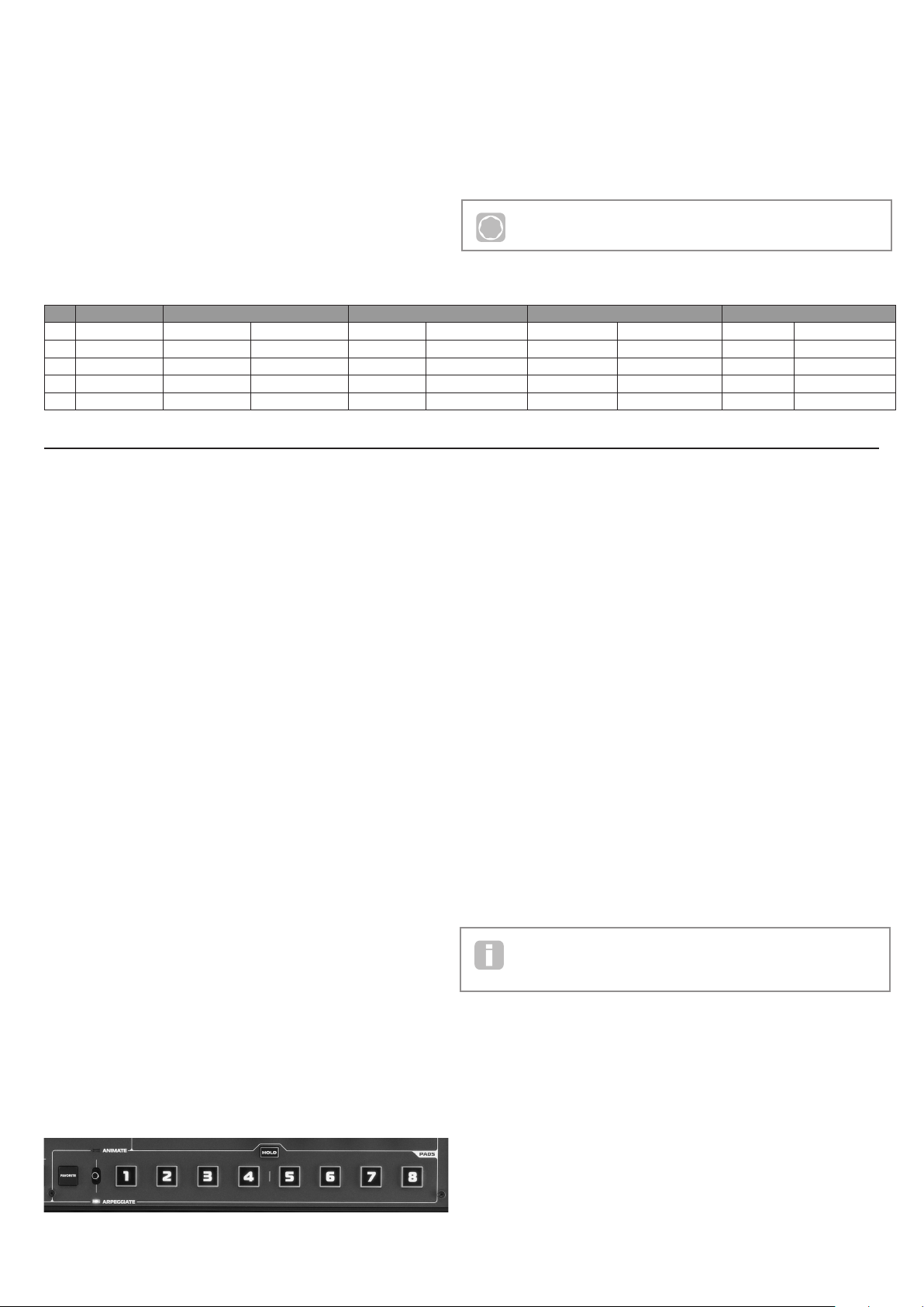
PAD section
15. PADS 1 to 8: a set of eight backlit, multicolour, pressure-sensitive pads,
which may be used in two prim ary ways – A nimate or Arpeggiate. Additionally,
in conjunction with the FAVOR ITE button [17], they may be used as “Quick
Load” buttons to recall preferred patches.
16. ANI MAT E/A RP EGGIAT E switch: A 2-position switch (spring-loaded to
return-to-centre), which assigns the pads [15] to act as Animate controls or
Arpeggiator pads.
17. FAVORITE button: used to store and recall preferred patches in conjunction
with the eight pads [15].
18. HOLD button: modifies the action of a pad [15] in Animate mode by “locking”
it in an “On” state.
ARP section
19. ON: backlit button to switch the Arpeggiator on and off. W hen selected ‘On’,
the eight pads [15] enter Arpeggiator mode and the Arpeggiator LED in the
Pads section illuminates.
20. LAT CH button: applies the Arpeg giator ef fect to the last note(s) played
continuously, until a subsequent key is pressed. LATCH can be pre -selected
so that it is effective as soon as the Arpeggiator is enabled.
21. TEMPO control : sets the tempo of the Arpeggiator pattern being played. An
adjacent LED blinks to give a v isual indicati on of the tempo, and the actual
BPM value is displayed on the LCD.
Misc
22. Dynamic M ic Input : an XLR socket for the connection of the supplied
gooseneck microphone, or alternative dynamic microphone (i.e., a mic not
requiring phantom power to operate ). The mic can be us ed with the MiniNova’s
vocoder and VocalTune features, or routed to the audio outputs. This input is
overridden when a jack plug is plugged in to EX T IN {8 } on the rear panel.
23. MASTER VOLUME: the level control for the main audio outputs and the
headphone output.
24. OC TAVE + and – buttons: these transpose the keyboard up or down one
octave each time they are pressed. A ssociated multi-colour LEDs co nfirm that
a transposition has been applied.
5
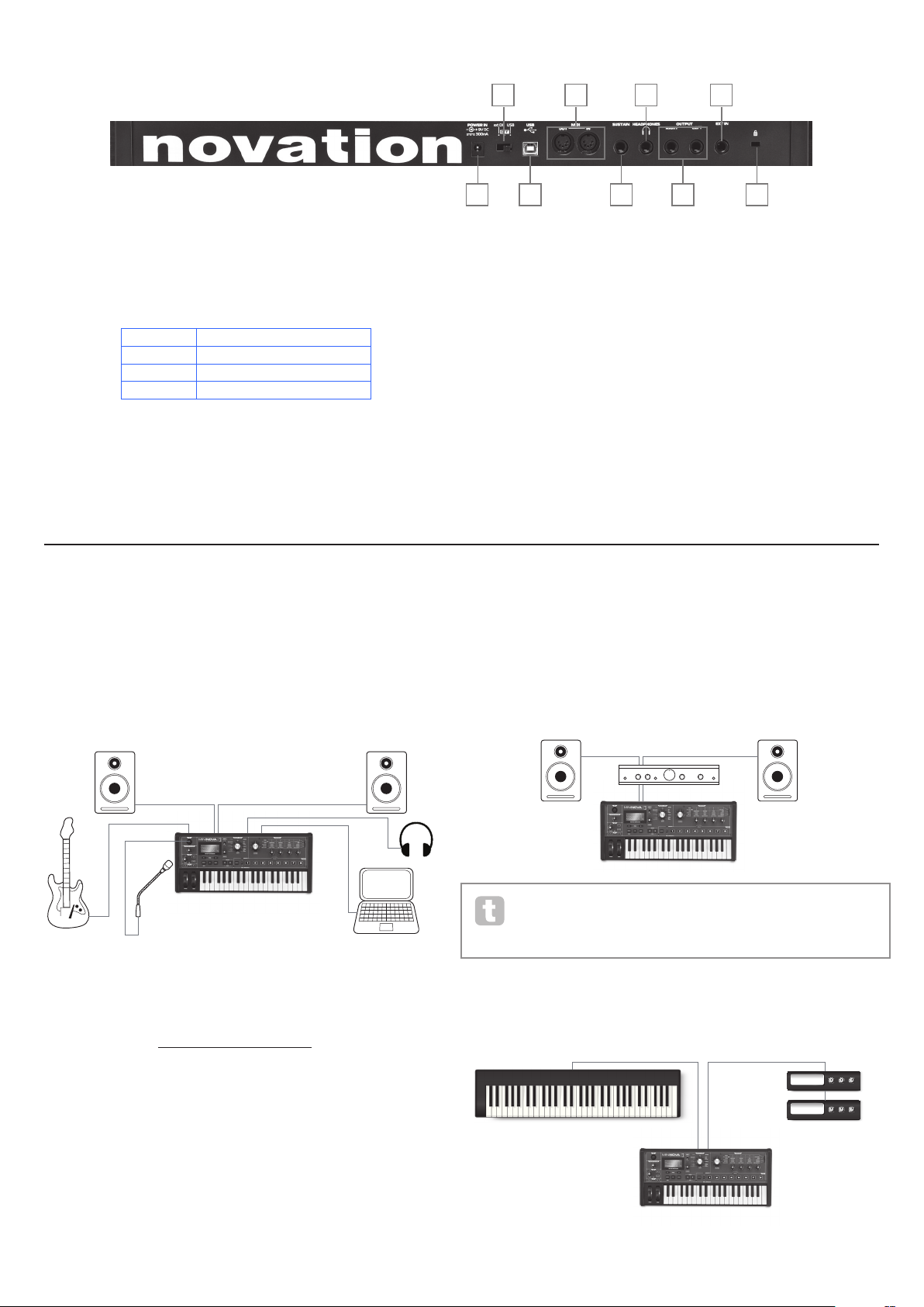
Rear view – connections
25. DC power connector: standard 2.2 mm socket for connecting the external
9 V DC PSU (supplied). See “Power requirements” on page 3.
26. On/off switch: 3-position switch:
POSITION ACTIO N
ext DC Enables external 9 V DC input
OFF Off
USB Enables power via USB port
27. USB port: Type B US B Type 1.1 (2.0-compatible) socket for connectio n to
PC or Mac
28. MIDI connectors: standard MIDI In/Out sockets (5-pin DINs)
29. Sustain pedal soc ket: 2-pole (mono) ¼” jac k socket for connection of a
sustain pedal. Both NO ( Normally Open) and NC (Normally Closed) pedal
types are comp atible ; if the pedal is connected when the MiniNova is p owered
on, the t ype will be automatically sensed during boot-up (provided your foot is
not on the pedal!). See “Parameter: Footswitch configuration” on page 13
for more information.
30. Headphones socket: 3-pole ¼” jack socket for stereo headphones. Phones
volume i s adjusted by the MASTER VOLU ME control [23 ].
31. OUTPUT LEFT and RIGHT: 2 x ¼” jack sockets carrying main stereo output.
Outputs are unbalance d, at +5 dBu maxi mum level .
32. EXT I N: ¼” jack socket for external instrument or line level audio inputs. This
input override s an XLR connector p lugged i nto the Dynamic Mic Input [22]
on the top panel. Input is balanced , and can accept a ma ximum input level of
0 dBu. The sensitivity of the input can be adjusted via the menu system (see
“Parameter: Input Gain” on page 12).
33. Kensing ton Lock Port: to secure your synthesizer.
G E T TI NG S TAR TE D
Standalone and computer operation – a foreword
The MiniNova may b e used as a standal one synthesizer, with or without MIDI connections
to/from other sound modules or keyboards. It may also be connected - via its USB port –
to a computer (Windows or Mac) running a DAW application. The MiniNova ca n then be
controlled entirely from the computer by using the MiniNova Editor plug-in. The MiniNova
Librarian is a separate software application, which greatly assists in the organising, saving
and rec all of patc hes.
Audio In
Audio Out
USB
MiniNova connected to a computer via USB.
USB transmits MIDI to and from the computer
The various ways of connecting the MiniNova to accommodate the various methods of
working are covered in the documentation supplied with the MiniNova Editor and M iniNova
Libra rian software packages. The Installers for this software, and the related USB drivers
may be dow nloaded from http://novationmusic.com/support.
When us ing the MiniNova with the MiniNova Editor, an EDITOR flag is disp layed on the
LCD to con firm the connection. Also note that a USB flag is displayed when M iniNova is
connected to a computer via USB, and valid data interchange has been est ablished.
STANDALONE OPERATION
– AUDIO AND MIDI
CONNECTIONS
The simplest and quickest way of get ting sta rted with the MiniNova is to connect the two
rear pa nel jack sockets marked OUTPUT LEFT and RIGHT {31} to the inputs of a stereo
amplifier, audio mixer, powered speakers, third-party computer sound card or other means
of monitoring the output.
Audio Out
If using the MiniNova with other sound modules, connect MIDI OUT {28} on the MiniNova
to MIDI IN on the first sound module, and daisy-chain fur ther modules in the usual way. If
using the MiniN ova with a master keyboard, connect the controller’s MIDI OUT to
MIDI IN on the MiniNova, and ensure that the master keyboard is set to M IDI channel 1
(the MiniNova’s default channel).
MIDI In
Controller Keyboard
MIDI Out
Sound Modules
Note: the MiniNova is not a computer MIDI inter face. M IDI can be trans mitted
between the MiniNova synth and com puter via the USB connection, but MIDI
cannot be transferred b etween the computer and ex ternal equipment via the
MiniN ova’s MIDI DIN ports.
25
27
28
29
30
31
32
33
26

6
With the amplifier or mixer off or muted, connect the AC adaptor to the MiniNova {25}, and
plug it into the AC mains. Turn the MiniNova on by moving the rear panel switc h {26} to
ext DC. After co mpleting its boot sequence, the LCD display will indicate the Patch which
has been loaded. If the TYPE/GENRE knob has not been moved since the last power-of f,
this will be the last Patch used. If the TYPE/GENRE knob has been moved, the Patch
loaded will be the lowest-numbered (or lowest alphabetically-sorted, depending on the
setting of the SORT switch) in the selected Type or Genre.
Turn on the mixer/amplifier/powered speakers, and turn up the Master Volume control
[23] until you have a healthy sound level from the speakers when you play the keyboard.
Using headphones
Instead of speakers via an amplifier and /or an audio mixer, you may wish to use a pair of
stereo headphones. These may be plugged into the rear panel headphone output socket
{30}. The main outputs are still active when headphones are plugged in. The MASTER
LEVEL control [23] also adjusts headphone level.
NOTE: The MiniNova headphone amp lifier is capable of outputting a high signa l level;
please take care when setting the volume.
A WORD ABOUT MENU
NAVIGATION
The MiniNova has been designed to give the player maximum control over sound character
and system operation with the minimum of hassle. The menu system is always entered by
pressing the MENU but ton [8 ]. The menu system consists of six individual menus :
Au dio In
Global
Arp
Chord
Ed it
Dump
Step bet ween the menus with the PAGE I and H buttons [7], and press OK [9 ] to enter the
desired menu. Use the PAGE buttons again to access the parameter you wish to change ;
use the D ATA control [6] to alter the parameter value.
The menu system can be exited by pressing the MENU/BACK button again; otherwise,
it will automatically time-out after a short period, and the screen will revert to display the
currently-loaded Patch information.
Scrolling through Patches
Your MiniNova comes pre-loaded with a set of facto ry Patches, which may be auditioned at
any time, providing you are not in the menu system. The Patches are arranged as 3 banks
(A to C), each with 128 patches ( 000 to 127). Ba nks A and B come pre-loaded with a full
set of fac tory Patches, while Bank C contains 128 copies of a n Initial Patch, which you can
either overwrite, or use as the basis for creating your own sounds. With the TYPE/GENRE
selector [4] set to ALL, either rotate the DATA control [6 ], or use the PATC H I and H
buttons [11] to step through the patches . The new sound is loaded as soon as the patch
data shows in the display.
The Patch set can be browsed in either bank and numerical order, or alphabetically by
name, according the set ting of the SORT switch [5].
Searching through Types or Genres
Apar t from being arranged in 3 banks, the patches are also categorised for you ac cording
to the type of sound; this ma kes finding suitable sounds much ea sier. Eac h patch
belongs to both a Genre and a Type; the Genre broadly indicates the musical area for
which the patch might be suitable, the Type alternatively arranges the patches by sonic
characteristics. Use the TYPE/GENRE control to select the Type or Genre in which you
are interested.
Once the Type or Genre has been specifi ed, the patch set can again be browsed either in
numerical or alphabetical order.
The Genres and Types are listed below:
TYPES GENRES
All
Vocoder/VocalTune Rock/ Pop
Bass R&B/Hip Hop
Keyboard/Lead Dubstep
Pad/Strings House/Techno
Arp/ Movement D&B/Breaks
Classic Synth
Using the FAVORITE button to load Patches
You can assign up to eight of your favourite Patches to the eight Per formance Pads, and
then quickly reload them without needing to search through the whole Patch list .
Assigning a Patch to a Pad
With the Patch already loaded, pre ss and hold the FAVORITE button [17], and
simultaneously pres s and hold a Pad button. The display will show A ss ig nIn , with
a 3 second countdown timer. Af ter 3 seconds, the display changes to Favorite
A ss ign e d, and the Patch i s now assigned to that Pad. Note that the Pad turns red to
confirm the assignment.
Loading a Patch from a Pad
Press and hold the FAVORITE button; all the Pads will flash blue (unless the currently-
loaded Patch is one that was previously assigned to a Pad, in which c ase, the Pad shows a
steady red). W hile they are flashing, press the Pad which has the Patch you want ass igned
to it, and that Patch will now be loaded. The LCD will confirm the new Patch by name.
Demo Mode
Press the two PAT CH I and H buttons [11] simultaneously, and the M iniNova will enter
Demo Mode. Using any control will cause a bri ef description its function to be dis played
on the LCD screen. Note that none of the controls ( except m aster volume) or keyboard are
active in Demo Mode.
MODIFYING SOUNDS -
USING THE PERFORMANCE
CONTROLS
The MiniNova is equipped with a set of controls specifically designed for use in live
performanc e. These allow you to modify the sound of the loade d patch in a variety of
interesting and sometimes startling ways!
These controls are found in the PERFORM, PADS and ARP areas of the control panel
(see items 12 - 21 on page 4 ).
Parameter Controls
While playing li ve, it is of ten desi rable to manually adjust some aspect or other of the sound
– i.e., “ tweak” a particular parameter. Although the MiniNova’s des ign allows you to access
all the parameters defining a particular sound, it is useful if the most important par ameters
that you need while playing live are readily available, on a convenient set of c ontrols. These
are the four rotar y controls to the ri ght of the control pa nel, see item 12 on page 4.
Use these four knobs in conjunction with the Perform Row Selec tor switch [13]. A n
LED will illuminate to show you which of the six banks of available parameters the knobs
are assigned to. Note that Rows 3 to 6 always c ontrol the same pa rameters, regardles s of
the patch you have loaded – though the actual effect of the control will quite likely sound
different! Rows 1 and 2 place the four knobs into “Tweak” mode, where the parameters
they control var y with the patch (see below).
Don’t worry too much at this stage what words like “Resonance” and “Sustain” mean – all
these ( and many other) terms are explained in much greater detail further on in the manual.
Just tr y to become familiar with the actual sonic effect you hear when you adjust each of the
parameters in turn, for di fferent catego ries of patch.
The four knobs used for “t weaking” will almost never be in the correct position
relative to the value of the parameter s they control which are stored as par t of the
currently-loaded Patch. For example, in the Patch A0 00 (“BassIsWet DC” ), the
value of the Filter Envelope Decay Time parameter is 27. If the Tweak control for this (RC2
in Row 4) is set to – say – 2 o’clock, the knob position implies a completely different value.
The LCD display includes two arrows which tell you which way to turn the knob to get the
knob position to “match” the stored parameter value. As long as Pot Pickup is set On (in
the Global Menu), the knob will have no effect until both arrows are off. If Pot Pickup is
Off, turning the knob will immediately alter the pa rameter, which may produce an audible
“jump”. Se e page 13 for more information on Pot Pickup.
Vocoder
Voc/MFX
T
u
r
n
T
u
r
n
T
u
r
n
Vocoder
Voc/MFX
7
Rows 1 and 2 – Tweak and (FX) Tweak controls
With either Rows 1 or 2 selected, the knobs will have a different ef fect dep ending on
the patch loaded. This is because the actual assignment of the controls forms part of the
Patch. You will find that all the factory Patches have some Tweak Controls pre-assigned,
but you can change their function or add others if you wish.
The best way of understanding the Tweak controls is to load a patch and play with them. Try
loading the Patch “Synchromatic 1 P S”, which can be found in the Arp /Movement T YPE*.
Select the TWEAK row with the Perform Row Selec tor switch [13]. As you play, adjust
each of the four TWEAK controls in turn to hear their ef fect. You will find that you can
introduce fur ther variations to the sound. Now select the ( FX) TWEAK row; you’ll find that
the TWEAK controls now do something different and the sound can be modified in other
ways – in this case, by altering the audio effects processing applied to the sound.
The imp ortant point to grasp here is that the effect of each TWEAK control on the sound
is spec ific to the patch. With different patches loaded, the TWEAK controls will alter
different sonic characteristics.
NOTE: RC4 is preset to control the level of FX level when Row 2 ((F X) TWEAK) is
selected. However, this can be changed in the T WEAK s ubmenu of the EDIT menu.
* You will be ab le to find thi s – or any Patch yo u know by nam e – more quickly by set ting SOR T to A-Z
and scrolling through the listed Patches alphabetically.
Rows 3 to 6 – Fixed Tweak contr ols
The function of the four rotary controls is predeter mined when any of Rows 3 to 6 is
selected. The table below lists the functions, and tells you where to look in the User Guide
to find out m ore information on the parameter controlled in each case.
P
Full details of the parameters each of the Tweak controls in Rows 3 to 6 are
available at the page number indicated in the table below.
Row Group RC1 RC2 RC3 RC4
Parameter More Info? Parameter More Info? Parameter More Info? Parameter More Info?
3
Filter Resonance
F1Re s pa ge 17
Trac kin g
F1Tra c k pag e 17
Type
F1Ty p e pa ge 17
Drive
F1Damnt pag e 17
4
Filter Envelope At tack
Flt At t pa ge 22
Decay
FltDec pag e 22
Sustain
FltSus page 22
Amount
F1Env2 p age 17
5
Amplitude Envelope Attack
Am pAtt pa ge 20
Decay
AmpDec pa ge 20
Sustain
AmpSus page 20
Release
Am p R el page 21
6
Oscillator Osc1 Vir tual Sync
O1V Sy n c p age 14
Osc 1 Density
O1Dense pa ge 15
Osc 2 Vir tual Sync
O2VSync pag e 14
Osc 2 Density
O2Dense page 15
The Filter knob
Adjusting the frequency of the synth’s primar y filter ( Filter 1) is probably the most
commonly-used method of sound modification. For this reason, Filter 1 Frequency has
its own dedicated control in the form of a large rotary control [14] next to the parameter
controls. Ex periment with di fferent types of patch to hear how changing the filter frequency
alters the characteristic of different types of sound.
Using the Pads as performance controls
The eight Pads below the parameter controls have a number of functions on the MiniNova. In
this section, we are concerned only with their use as perfor mance controls . To enable the Pads
for per formance use, set the AN IM ATE /AR PEGGI ATE switch [16] to A NI MATE .
Like the T WEAK controls, the precise ef fect that each Pad w ill have on the characteristic
of the sound is Patch-dependent. Again, the best way of understanding what they can
do is to load a Patch and p lay with them. Load the Patch “Cry4Moon DF” - which can be
found in the Keyboa rd/ Lead T YPE* - and lightly touch each of the pads in turn while playing
norma lly. You’ll find that when you touch a pad, something distinctive ha ppens to the
sound. Try loading different types of Patch to see what ef fect the Pads have in each. Note
that not all Patche s have all ei ght Pads assigned.
Later in the manual, you will discove r how to reassign the Pads to make specifi c parameter
changes to any given patch, and that the se assignments remain with the patch for your
future use.
* You will be ab le to find thi s – or any Patch yo u know by nam e – more quickly by set ting SOR T to A-Z
and scrolling through the listed Patches alphabetically.
The Arpeggiator
The MiniNova has a powerful Arpeggiator feature which allows arpeggios of varying
compl exity and rhythm to be played and manipulated in real-time. If a single key is pressed,
the note will be retriggered by the Arpeggiator. If you play a c hord, the Arpeggiator
identifies its notes and plays them individually in sequence (this is termed an arpeggio
pattern or ‘arp se quence’); thus if you play a C major triad, the selected notes will be C, E
and G.
The MiniNova Arpeggiator is enabled by pre ssing the ARP ON button [19]; its backlight
will confirm and the eight Pads will turn red. H olding a note down will repeat the note in
the sequence, a nd you will see the Pads’ illumination changing to purple a s the pattern
progresses. Initially all enabled beats in the sequenc e are sounded, but if you pres s a Pad,
the beat corres ponding to that Pad’s position will now be omitted from the sequence,
generating a rhy thmic pattern. The ‘deselected’ Pads will not illuminate. A ‘deselected’ Pad
may be re-enabled by tapping it a second time.
Arpeggiator operation in the MiniNova is controlled by the three ARP buttons [19], [20] &
[21]: ON, LAT CH and TEMPO. The ON button enable s or disables the Arpeggiator.
The L ATCH button plays the currently selecte d arp sequence repeatedly without the keys
being held. LATC H can also be pressed before the Arpeggiator is enabled. When the
Arpeggiator is enabled, the MiniNova will immediately play the arp sequence defined by the
last set of notes played, and will do so indefinitely. The tempo of the ar p sequence is set by
the TEMPO control; you can make the sequence play faster or slower by altering this. See
page 13 for further details.
The Vocoder
Your MiniNova comes with a Vocoder section, whic h allows you to create some really great
sounds by combining synth sounds with either a voice or another instrument such as a guitar.
To use the Vocoder, rst connect a microphone (one is supplied with your MiniNova) to the
MIC socket [22] on the top panel. A lternatively, you can plug a guitar or other instrument
into the E XT IN socket {8 } on the rear panel ( this will disconnect the mic socket). Nex t,
you need to set the audio gain of the mic or instrument. To do this, press MENU [8], select
Audio In using the DATA wheel [6] , then pre ss OK [9] . This will open the menu system,
and Audio In is the first menu displayed . The first menu item in the Audio Menu is Input
Gain (In pt Gain); ad just the input gain with the D ATA wheel [6] while noting the signal
level as displayed at the top of the LCD screen as a horizontal bargraph meter. Ensure that
the loudest audio level does not cause the OVER segment to illuminate.
Set the TYPE/GENRE control [4] to VOCODER/VOCALTUNE, and select a patch from
the available subset. Now hold one or more keys down and sing into the microphone (or
play the instrum ent connected at E XT IN ). You will hear the sound of the synth, modified by
the external audio input. As with a ny other patch, you can alter various parameter s with the
FI LTE R and four rotar y encoders in the PERFORM section, or use the Animate functions
as described above.
As with all the other performance controls, we recommend that there is no substitute for
experimentation to get an understanding of how the various controls interact.
Pitch and Mod wheels
The MiniNova is fitted with a standa rd pair of synthesizer control wheels adjac ent to the
keyboard, PITCH and MOD ( Modulation ). The PITCH control is spring-loaded and always
returns to the centre position.
Moving PITCH will always raise or lower the pitch of the note( s) being played. The range of
operation can b e set via the menu system, from a semitone to an octave, in semitone steps.
The MOD whee l’s precise function varies with the Patch loaded; it is used in general
to add expression or various elements to a synthesise d sound. A c ommon use is to add
vibrato to a sound; another is to control the speed of a “vir tual” rotary speaker.
It is possible to a ssign the MOD wheel to control any p arameter constituting the sound
– or a combination of parameters simultaneously. This topic is discussed in more detail
elsewhere in the manual. See “Wh at is Legato?” on page 21.
Note that two of the factor y Vocoder Patc hes, “Aaah 1” (B073) and “Aaa h 2” (B074),
do not make use of the built-in mi cropho ne. Although these use the M iniNova’s
Vocoder functions, they use xed formants which are stored with the Patches.
8
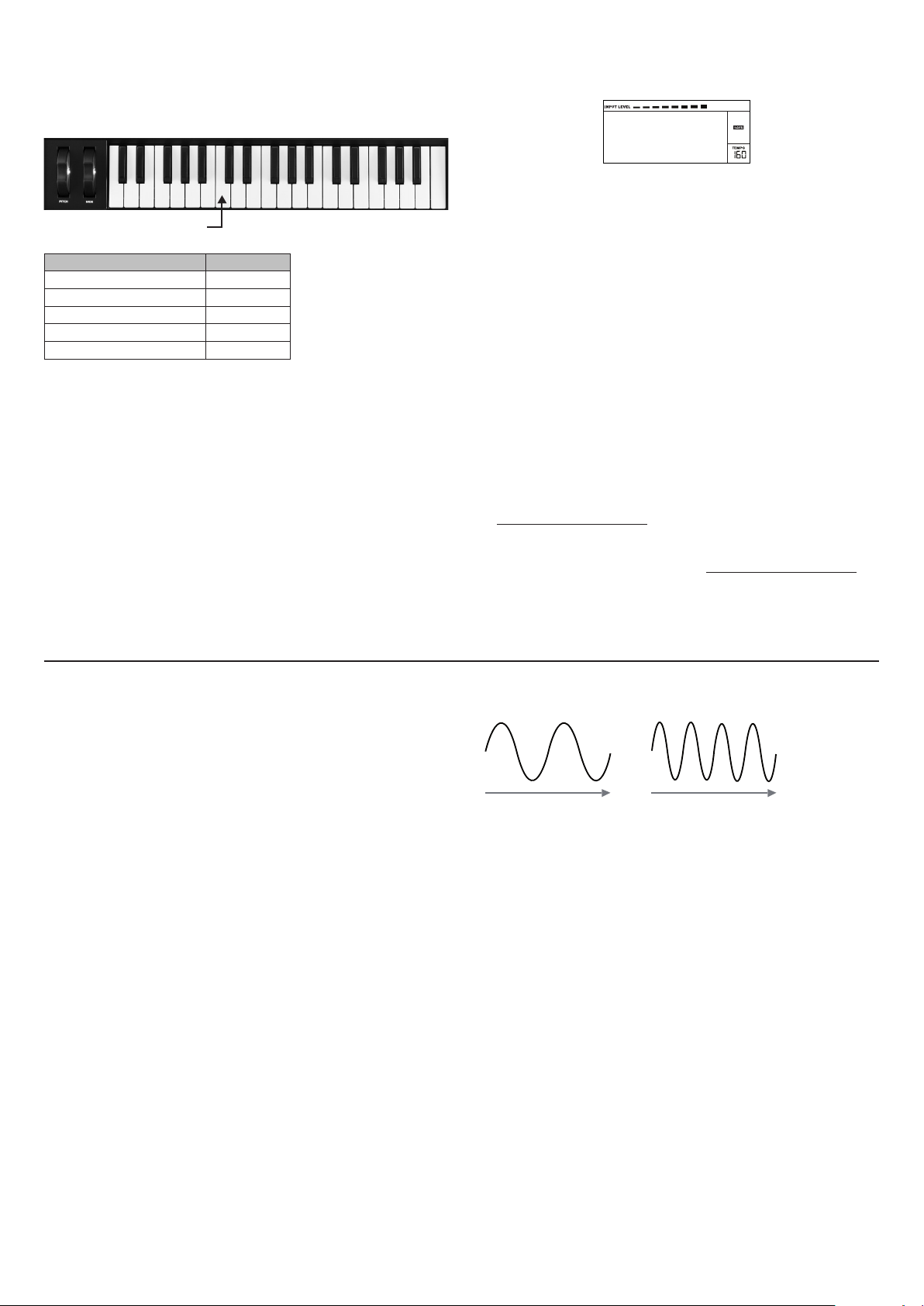
Octave Shift
These two backlit buttons [24] transpose the keyboard up or down one octave each time
they are pressed, to a maximum of four octaves . The colour displayed by the buttons
indicates the number of octaves shi fted: when both LEDs are off (the default state), the
lowest note on the keyboard is one octave b elow Mid dle C.
Middle C
SHIFT COLOUR
(no buttons pressed) LEDs off
± 1 octave Red
± 2 octaves Magenta
± 3 octaves Purple
± 4 octaves Blue
Normal keyboard pitch may be reinstated at any time by pressing both Octave buttons
together.
Storing a Patch
Novation have worked hard to create a really useful and great-sounding set of factory
Patches, and we are sure that many of them will meet your needs without further
modifi cation. However, the scope for altering – or creating comp letely new - sounds in the
MiniN ova is almost limitless, and when you have done so, you will probably want to save the
sounds for future use.
It is possible to store or write your own patches directly into the MiniNova without using
the MiniNova Editor and Librarian software applications. Once any of the pa rameters of a
Patch have been cha nged, the SAVE flag will illuminate in the LCD, to re mind you that you
are no longer working with an unmodified Patch. To save the modified Patch:
1. Press the SAVE button [10] , which will display the name that the Patch had
when it was first loaded.
NOTE: The Memory Protect function is active by default, so you are likely to see the words
Memory Protect ! flash on-screen. It will not be possible to save a modifie d version of the
current patch, without turning this option off. See “Parameter: Memory Protection” on
page 12.
Memory
Protect
Note that the screen will prompt you for a new name for the modified vers ion (Nam e?), and
that the current name will b e offered as a suggestion, with the first character flashing . Use
the DATA control [ 6] or the PATCH I and H but tons [11] to select a different alphanumeric
character.
• Use the PAG E I and H buttons [7] to move to the next character, and continue in this
manner until the new name ha s been entered.
• Press SAVE aga in. You will now be prompted to choose the location where the new
Patch is to be saved. The location of the original Patch will be offered as the default;
if you choose this , the original patch data will be overwritten. Use the D ATA control
[6], or PATCH I and H buttons [11] to select a different loc ation. N ote that Bank C
(128 locatio ns) has been lef t empty for you to save your own patches; thi s avoids
overwriting any of the original versions.
• Press SAVE aga in, and you will now be p rompted to choose the TYPE Category
that will allow MiniNova’s sorting system to retrieve it. Use the DATA control to select
the most appropriate one, and press SAVE again.
• You will finally be prompted to choose the GENRE for filing purposes. Use the DATA
control to select the most appropriate, and press SAVE again.
• The scr een will now confir m the new Patch with the message
Patch Saved. Note that whichever location is chosen for the new Patch, any
Patch data already saved to th at location will be lost.
NOTE: A faster method of managing patches (writing, loading, renaming, reordering etc.)
is by using the downloadable MiniNova Librarian. This can be downloaded free of charge
from www.novationmusic.com/support.
Updating the MiniNova’s Operating System
OS update files will be available from time to time at www.novationmusic.com/support in
the form of a MIDI SysEx file. The update proc edure requires the MiniNova to be connected
via USB to a computer which has first had the necessar y USB drivers installed . Full
instructions on performing the update will be supplied with the download.
SYNTHESIS TUTORIAL
This section covers the subject of sound generation in more detail and discusses the
various basic features available in the MiniNova’s sound generation and processing blocks.
It is recommended that this chapter is read carefully if analogue sound synthesis is an
unfamiliar subject. Users familiar with this subject can skip this chapte r and move on to the
next chapter.
To gain an understanding of how a synthes izer generates sound it is helpful to have an
appreciation of the components that make up a sound, both music al and non-musical.
The only way that a sound may be detected is by a ir vibrating the eardrum i n a regula r,
perio dic manner. The brain interprets these vibrations (very accurately ) into one of an
infinite number of different types of sound.
Remar kably, any sound may be described in ter ms of just three properti es, and all sounds
always have them. They are:
• Pitch
• Tone
• Volume
What makes one sound different from anothe r is the relative magnitudes of the three
properties a s initially present in the sound, and how the properties change over the
duration of the sound.
With a musical sy nthesizer, we deliberately set out to have precise control over these three
properties a nd, in particular, how they can be changed during the “li fetime” of the sound.
The properti es are of ten given different names: Volume may be refer red to as Amplitude,
Loudness or Level, Pitch as Frequency and Tone as Timbre.
Pitch
As state d, sound is perceived by air vibrating the ear drum. The pitch of the sound is
determined by how fast the vibratio ns are. For an adult human, the slowest vibration
perce ived as sound is about twent y times a second, w hich the b rain interprets as a bass
type sound; th e fastest is many thousands of times a second, w hich the b rain interprets as
an high treble type sound.
Time Time
A B
If the number of pe aks in the t wo waveforms (vibrations) are counted, it will be seen that
there are exactly twice as many peaks in Wave B as in Wave A. (Wave B is actually an
octave higher in pitch than Wave A). It is the number of vibrations in a given period that
determines the p itch of a sound. This is the reason that pitch is sometimes referred to as
frequency. It is the number of waveform peaks counted during a given period of time which
defines the pitch, or frequency.
Tone
Musical sounds consist of several different, related pitches occurring simultaneously. The
lowest is referred to as the ‘ fundamental’ pitch and c orresponds to the perceived note of
the sound. Other pitches making up the sound which are related to the fundamental in
simple mathematical r atios are called harmonics. The relative loudness of each h armonic
as compared to the loudness of the fundamental determines the overall tone or ‘timbre’ of
the sound.
Consider two instruments such as a harpsichord and a piano playing the same note on the
keyboard and at equal volume. Despite having the same vo lume and pitch, the instruments
still sound distinctly different. This is because the different note-ma king mechanisms of
the two instruments generate dif ferent sets of harmonics; the har monics present in a piano
sound are different to those found in a harpsichord sound.
Volume
Volume, w hich is of ten referred to as the amplitude or loudness of the sound is determined
by how large the vibrations are. Very s imply, listening to a piano fro m a metre away would
sound louder than if it were fifty metres away.
9
Volume
A B
Having shown that just three elements may defi ne any sound, these elements now have to
be related to a Musical synthesizer. It is logical that a different section of the Synthesizer
‘synthesizes’ (or creates) these different elements.
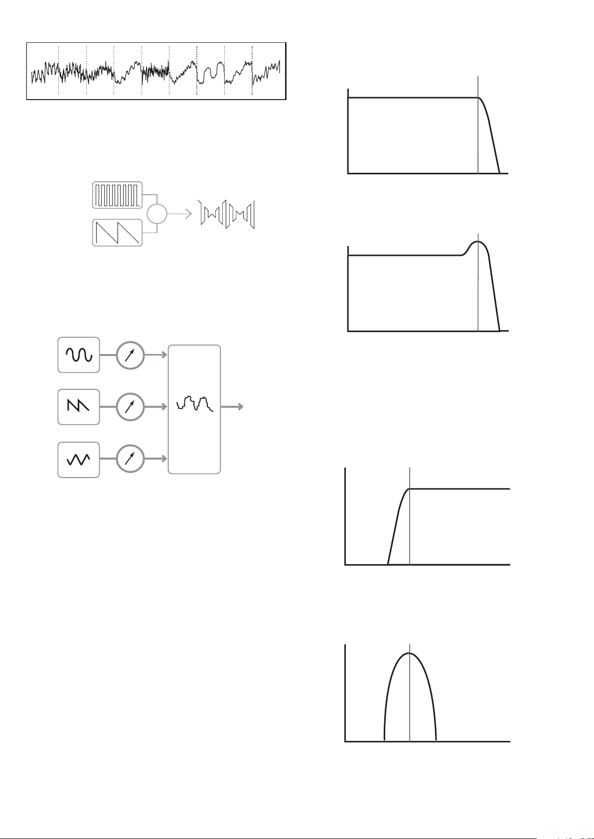
One sec tion of the synthesizer, the Oscillators, provide raw waveform signals whi ch
define the pitch of the sound along with its raw harmonic content (tone). These signals
are then mixed together in a section called the Mixer, and the resulting mixture is then fed
into a section called the Filter. This m akes fur ther alterations to the tone of the sound, by
removing (filtering) or enhancing cer tain of the harmonics. Lastly, the filtere d signal is fed
into the Amplifier, which determines the final volume of the sound.
Oscillators Mixer Filter Amplifier
Additional synthesizer sections - LFOs and Envelopes - provide further ways of altering the
pitch, tone and volume of a sound by interacting with the Oscillators, Filter and
Ampli fier, providing changes in the character of the sound which can evolve over time.
Because LFOs’ and Envelopes’ only purpose is to control (modulate) the other
synthesizer sections, they are commonly known as ‘modulators’.
These various synthesizer sections will now be covered in more detail.
The Oscillators And Mixer
The Oscillator is really the hear tbeat of the Synthesizer. It generate s an electronic wave
(which creates the vibrations when eventu ally fed to a loudspeaker). This Waveform is
produced at a controllable musical pitch, initially determined by the note played on the
keyboard or contained in a received MIDI note message. The initial distinctive tone or
timbre of the waveform is actually determined by the waveform’s shape.
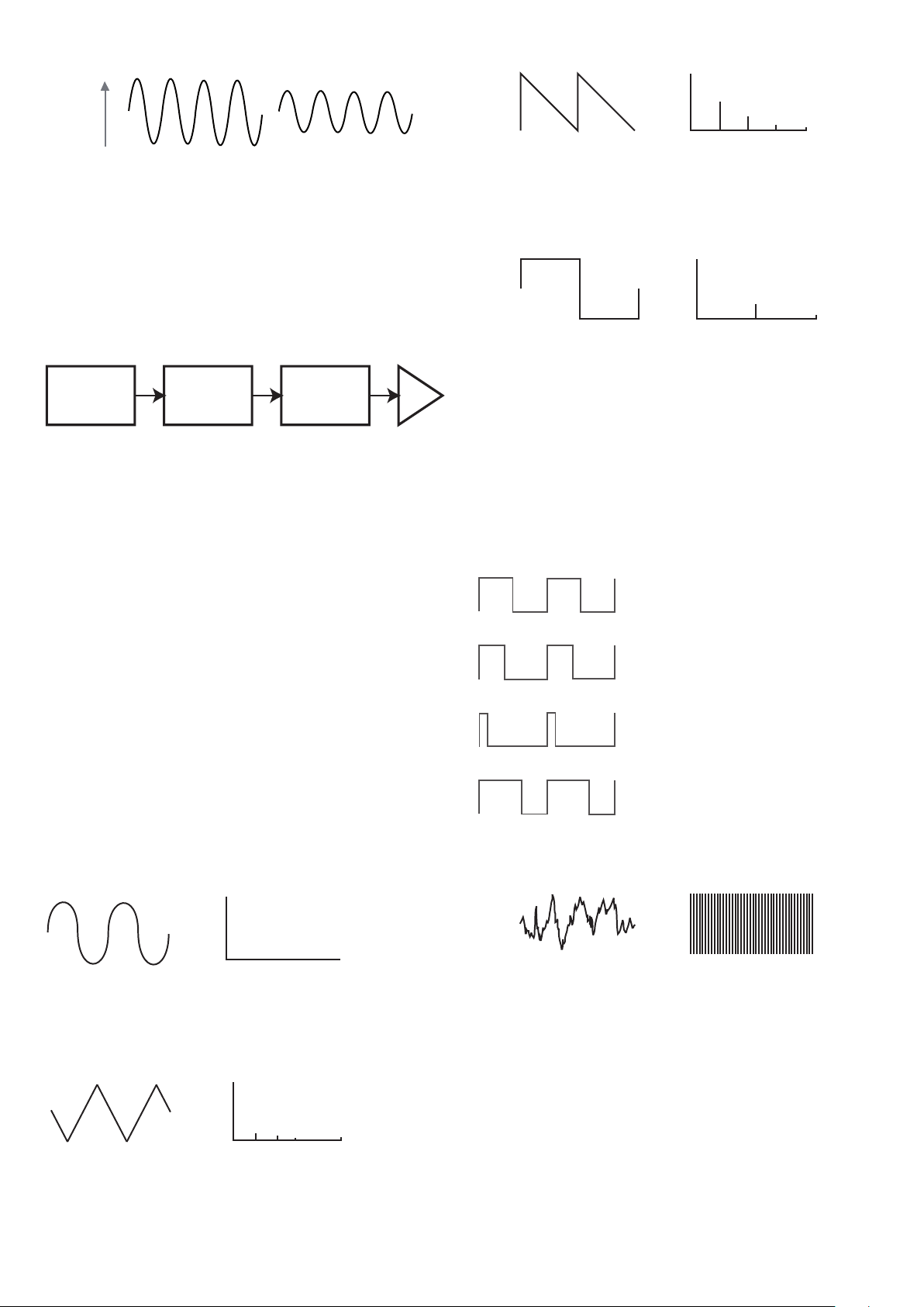
Many years ago, pioneer s of music al synthesis dis covered that just a few distinctive
waveforms contained many of the most useful harmonics for mak ing musi cal sounds. The
names of these waves reflec t their actual shape when viewed on an instrument called an
Oscilloscope, and the se are: Sine waves , Square waves, Saw tooth waves, Triangle waves
and Noise.
Each waveform shape (exc ept noise) has a specific set of musically-related harmonics
which can be manipulated by further sections of the synthesizer.
The diagrams below show how these waveforms look on an oscilloscope, and illustrate
the relative levels of their harmonics. Remember, it is the relative levels of the various
harmonics present in a waveform which deter mine the tone of the final sound .
Sine Waves
These possess just a single harmonic. A sine waveform produces the “purest” sound
because it only has its single pitch (frequency).
Triangle Waves
Volume
Harmonic
1 3 5 7
Triangle Wave
These contain only odd harmonics. The vo lume of each decre ases as the square of its
position in the harmonic series. For example, the 5th harmonic has a volume 1/25th of the
volume of the fundamental.
Sawtooth Waves
Volume
Harmonic
1
Sine Wave
Sawtooth Wave
Volume
Harmonic
Square Wave
Volume
Harmonic
1 2 3 4 5
Volume
Harmonic
1 3 5 7
Triangle Wave
1 2 3 4 5
These are rich in harmonics, and containing both even and odd harmonics of the
fundamental frequency. The volume of each is inversely proportional to its position in the
harmonic series.
Square / Pulse Waves
Square Wave
Volume
Harmonic
1 2 3 4 5
Volume
Harmonic
1 3 5 7
Triangle Wave
These only have odd harmonics, which are at the same volume as the odd harmonics in a
sawtooth wave.
It will b e noticed that the square waveform spends equal amounts of time in its ‘high’ state
and its ‘low’ state. This ratio is known as the ‘duty cycle’. A square wave always has a duty
cycle of 50% which means it is ‘high’ for half the cycle and ‘ low’ for the other ha lf.
In the MiniNova , it is possible to adjust the duty cycle of the basic square waveform to
produce a waveform which is more ‘rectangular’ in shape. The se are often known as Pulse
waveforms. As the waveform becomes more and more rectangular, more even harmonic s
are introduced and the waveform changes its character, becoming more ‘nasal’ sounding.
The width of the pulse waveform (the ‘Pulse Wi dth’) can be altered dynamically by a
modulator, which results in the harm onic content of the waveform co nstantly changing. Thi s
can give the waveform a very ‘ fat’ quality when the pulse width is altered at a moderate rate.
50%
40%
10%
60%
It does not make any difference to how
a pulse waveform sounds whether the
duty cycle is 40 % or 60%, since the
waveform is just “inverted” and the
harmonic content is exactly the same.
Noise Waves
Volume
Harmonic
1
Sine Wave
Sawtooth Wave
Volume
Volume
Harmonic
Square Wave
Volume
Harmonic
1 2 3 4 5
Volume
Harmonic
1 3 5 7
Triangle Wave
1 2 3 4 5
1 2 3 4 5
These are basically random signals, and have no one fundamental frequency (and therefore
no pitch proper ty). A ll frequencies are at the same volume. Because they possess no pitch,
noise signals are often useful for creating sound effects and percussion type sounds.
Digital Waveforms
In addition to the traditional types of Oscillator waveforms detailed above, the MiniNova
also offers a set of carefully selected, digitally-generated waveforms containing useful
harmonic elements normally difficult to produce using traditional Oscillators.
Wavetable s
A “wavetable” is es sentia lly a group of digital waveforms. The MiniNova’s 36 wavetables
each contain 9 separate di gital waveforms. The benefit of a wavetable is that consecutive
waveforms in the wavetable can be blended. Some of the MiniNova’s wavetables contain
waveforms with similar harmonic content, while others contain waveforms with greatly
differing harmonic content. Wavetables come ali ve when the ‘wavetable index’ – the
position within the wavetable - is mo dulated , resulting in a sound that continually changes
character, either smoothly or abruptly.
Volume
Harmonic
1
Sine Wave
Square Wave
Volume
Harmonic
1 2 3 4 5
Volume
Harmonic
1 3 5 7
Triangle Wave
10
9 Waves make up a wave table
Ring Modulation
A Ring Modulator is a sound generator that takes signals from two of the MiniNova’s
oscillators and effectively “multiplies” them together. The MiniN ova has 2 Ring Modulators,
one takes Osc 1 and Osc 3 as inputs, and th e other takes Osc 2 and Osc 3. The resulting
output depends on the various frequencies and harmonic content present in each of the
two oscillator signals , and will consist of a series of sum and difference frequencies as well
as the frequencies present in the original signals.
OSC 1
OSC 3
X
The Mixer
To extend the range of sounds that may be produced, t ypica l analogue synthesizers have
more than one Oscillator. By using multiple Oscillators to create a sound, it is possible
to achieve very interesting harmonic mixes. It is also possible to slightly detune individual
Oscillators against each other, which creates a very warm, ‘fat’ sound. The MiniNova’s
Mixer a llows mixing of three indep endent O scillators, a separate Noise Oscillator and two
Ring Modulator sources.
The Filter
The MiniNova is a subtractive music synthesizer. Subtractive implies that par t of the sound
is subtracted somewhere in the synthesis process.
The Oscillator s provide the raw waveforms with plenty of harmonic content and the F ilter
section subtracts some of the harmonics in a controlled manner.
14 types of Filter are availabl e on the MiniNova, though these are varieties of three basic
filter types: L ow Pass, Band Pass and High Pass. The type of Filter most commonly
found on synthesizers is the Low Pass type. With a Low Pass Filter, a cut-off point
(or cut-off frequency ) is chosen and any fr equencies below the point are passed, and
frequencies a bove are filtered out. The set ting of the Filter Frequency parameter dictates
the point below which frequencies are removed. This process of removing harmonics
from the waveforms has the ef fect of changing the sound’s character or timbre. When the
Frequency parameter is at maximum, the filter is completely “open” and no frequencies ar e
removed from the raw Oscillator waveforms.
In prac tice, there is a gradual (rather th an a sudden) reduction in the volume of the
harmonics above the cut-off point of a Low Pass Filter. How rapidly these harmonic s
reduce in volume as frequency increases a bove the cut-off point is determined by the
Filter’s slope. The slope is measured in ‘volume units per oct ave’. Since Volume is
measured in decibels , this slope is usually quoted as so many decibels per octave
(dB /oct) . Typical va lues are 12 dB/oct and 24 dB/oct. The hi gher the number, the g reater
the rejection of harmonics above the cut-of f point, and the more pronounced the filtering effect.
A further important parameter of the Filter is its Re sonance. Frequencies at the cut-off point
may be increased in volume by the Filter Resonance control. This is useful for emphasizing
cert ain harmonics of the sound.
As Resonance is increased, a whistling-like quality will be introduced to the sound passing
through the filter. When set to very high levels, Resonance actually causes the filter to
self-oscillate whenever a signal is being passed through it. The resulting whistling tone
being produced is actually a pure sine wave, the pitch of which depends on the setting of
the Frequency control (the filter’s cut-off point). This re sonance-produced sine wave can
actually be used for some sounds as an additional sound source i f wished.
The diagram below shows th e response of a typical low pass filte r. Frequencies above the
cut-off point are reduced in volume.
Volume
Frequency
Cut-off
Frequency
When re sonance is added, frequencies at the cut-off point a re boosted in volum e.
Volume
Volume
Frequency
Cut-off
Frequency
Frequency
Cut-off
Frequency
In addition to the traditional Low Pass Filter type, there are also High Pass and B and Pass
types. The ty pe of Filter used is selected with the Filter Type parameter.
A High Pa ss Filter is similar to a Low Pass Filter, but works in the “opposite sense”, so that
frequencies b elow the cut-off point are removed. Frequencies above the cut-off point a re
passed. When the Filter Frequency parameter is set to zero, the filter is completely open
and no frequencies are removed from the raw Oscillator waveforms.
Volume
Volume
Frequency
Cut-off
Frequency
Volume
Volume
Frequency
Cut-off
Frequency
Frequency
Cut-off
Frequency
Frequency
Cut-off
Frequency
When a Band Pass F ilter is used, only a narrow band of frequencies centered around the
cut- off point are p assed. Frequencies above and below the band are removed. It is not
possible to fully open this type of F ilter, and allow all frequencies to pas s.
Volume
Volume
Frequency
Cut-off
Frequency
Volume
Frequency
Cut-off
Frequency
Frequency
Cut-off
Frequency
Envelopes And Amplifier
In earlier paragraphs, the synthesis of the pitch a nd the timbre of a sound were described.
The nex t part of the Synthesis Tutorial describes how the volume of the sound is controlled.
The volume of a note created by a musical instrument often varies greatly ove r the duration
OSC 1
OSC 1 VOLUME
OSC 2 VOLUME
OSC 3 VOLUME
COMPLEX
WAVEFORM
MIX OF
OSC1, 2 AND 3
MIXER
INPUT TO
FILTER
OSC 2
OSC 3
11
of the note, according to the t ype of instrument.
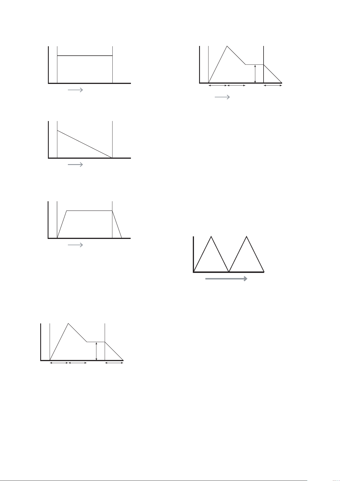
For example, a note played on a n Organ quickly attains full volume when a key is pressed.
It stays at full volume until the key is released, at which point the volume level falls instantly
to zero.
TIME
KEY "ON" KEY "OFF"
VOLUM E
A Piano note quick ly attains full volume after a key is pre ssed, and gradually falls in volume
to zero af ter several seconds, even if the key is held.
TIME
KEY "ON" KEY "OFF"
VOLUM E
TIME
KEY "ON" KEY "OFF"
VOLUM E
A String Section emulation only at tains full volume gradually when a key is pressed. It
remains at full volume while the key is held down, but once the key is released, the volume
falls zero fairly slowly.
TIME
KEY "ON" KEY "OFF"
VOLUM E
TIME
KEY "ON" KEY "OFF"
VOLUM E
TIME
KEY "ON" KEY "OFF"
VOLUM E
In an analogue synthesizer, changes to a sound’s character which occur over the duration
of a note are controlled by a section called an Envelope Generator. The MiniN ova has 6
Envelope Generators (called Env 1 to Env 6). Env 1 is always related to an Amplifier, which
controls the note’s amplitude – i.e., the volume of the sound - when the note is playe d.
Each envelope generator has four main controls which are used to adjust the shape of the
envelope.
Attack Time
Adjusts the time it takes af ter a key is pressed for the volume to climb from zero to full
volume . It can be u sed to create a sound with a slow fade-in.
TIME
KEY "ON" KEY "OFF"
VOLUM E
ATTACK DECAY RELEASE
SUSTAIN
TIME
KEY "ON" KEY "OFF"
VOLUM E
TIME
KEY "ON" KEY "OFF"
VOLUM E
KEY "ON" KEY "OFF"
VOLUM E
Decay Time
Adjusts the time it takes for the volume to fall from its initial full volume to the level set by the
Susta in control while a key is held down.
Sustain Level
This is unlike the other Envelope controls in that it sets a level rather than a period of tim e.
It sets the volume level that the envelope remains at while the key is hel d down, af ter the
Decay Time has ex pired.
Release Time
Adjusts the time it takes for the volume to fall from the Sust ain level to zero once the key is
relea sed. It c an be used to create sounds that have a “fade-out ” quality.
A typical synthesizer w ill have one or more envelopes . One envelope is always applied to
the amplifier to shape the volume of each note played. Additional envelopes can be used to
dynamically alter other sections of the synthesizer during the lifetime of each note.
The MiniNova’s second Envelope Generator ( Env 2) is used to modify the filter cut-off
frequency over the lifetime of a note.
In the MiniNova , Envelope Generators 3 to 6 can be used for special purposes, such as
modulating the Wavetable index or FX levels.
ATTACK DECAY RELEASE
SUSTAIN
TIME
KEY "ON" KEY "OFF"
VOLUM E
TIME
KEY "ON" KEY "OFF"
VOLUM E
ATTACK DECAY
RELEASE
SUSTAIN
SUSTAIN
RATE
TIME
KEY "ON" KEY "OFF"
VOLUM E
ATTACK DECAY
RELEASE
SUSTAIN
SUSTAIN TIME
TIME
KEY "ON" KEY "OFF"
VOLUM E
ATTACK DECAY RELEASE
SUSTAIN
TIME
KEY "ON" KEY "OFF"
VOLUM E
ATTACK DECAY RELEASE
SUSTAIN
TIME
KEY "ON" KEY "OFF"
FILTER
CUT-OFF
LFOs
Like the E nvelope G enerators, the LFO section of a synthesizer is a Modul ator. Thus
instead of being a part of the sound synthesis itself, it is used to change (or modulate)
other sections of the synthesizer. For example, an LFO c an be used to alter Oscillator pitch,
or Filter cut-off frequency.
Most musical instruments produce sounds that vary over time both in volume and in pitch
and timbre. Sometimes these variations can be quite subtle, but still contribute greatly
towards characterising the final sound.
Where as an Envelope is used to control a one-off modulation during the lifetime of a
single note, LFOs modulate by using a repeating cyclic waveform or pattern. As discussed
earli er, Oscillators produce a constant waveform which can take the shape of a repeating
sine wave, triangle wave etc. LFOs produce waveforms in a similar way, but norma lly at a
frequency which is too low to produce a sound that the human ear could perceive. (In fact,
LFO stands for Low Frequency Oscillator.)
As with an Envelope, the waveforms generated by the LFOs may be fed to other parts of
the synthesizer to create th e desired changes over time – or ‘movements’ - to the sound.
The MiniNova has three independent LFOs, which m ay be used to m odulate different
synthesizer sections and can run at different speeds.
A typical waveshape for an LFO would be a Triangle wave.
TIME
PITCH
Imagine this very low frequency wave being applied to an Oscillator’s pitch. The result is
that the pitch of the Oscillator slowly rises and falls above and below its original pitch. This
would si mulate, for example, a violinist moving a finge r up and down the string of the
instrument whilst it is being bowed. This subtle up and down movement of pitch is referred
to as the ‘Vibrato’ effect.
Alternatively, if the same LFO signal were to modulate the Filter cut-off frequency instead of
the Oscillator pitch, a familiar wobbling effect known as ‘wah- wah’ would be result.
As well as setting up various sections of the synthesizer to be modulated by LFOs,
additional Envelopes may also be used as modulators at the same time. Clearly, the more
Oscillators, Filters, Envelopes and LFOs there are in a synthesizer, the more powerful it is.
Summary
A synthe sizer can be broken down into five main sound generating or sound modifying
(modulating) blocks.
1. Oscillators that generate waveforms at a various pitches.
2. A Mixer that mixes the outputs from the Oscillators together.
3. Filters that remove certain harmonics, changing the character or timbre of the sound.
4. An Amplifier controlled by an Envelope generator, which alters the volum e of a sound
over time when a note is played.
5. LFOs and Envelopes that can be used to modulate a ny of the above.
Much of the enjoyment to be had with a Synthesizer is with experimenting with the factory
preset sounds and creating new ones. There is no substitute for ‘hands on‘ experience.
Expe riments with adjusting the MiniNova’s many parameter s will eventually lead to a fuller
under standing of how the various c ontrols alter and h elp shape new sounds.
Armed with the knowledge in this chapter, and an understanding of what is actually
happe ning in the machine when tweaks to the knobs and switches are made, the process
of creating new and exciting sounds will become easy - Have fun.
12
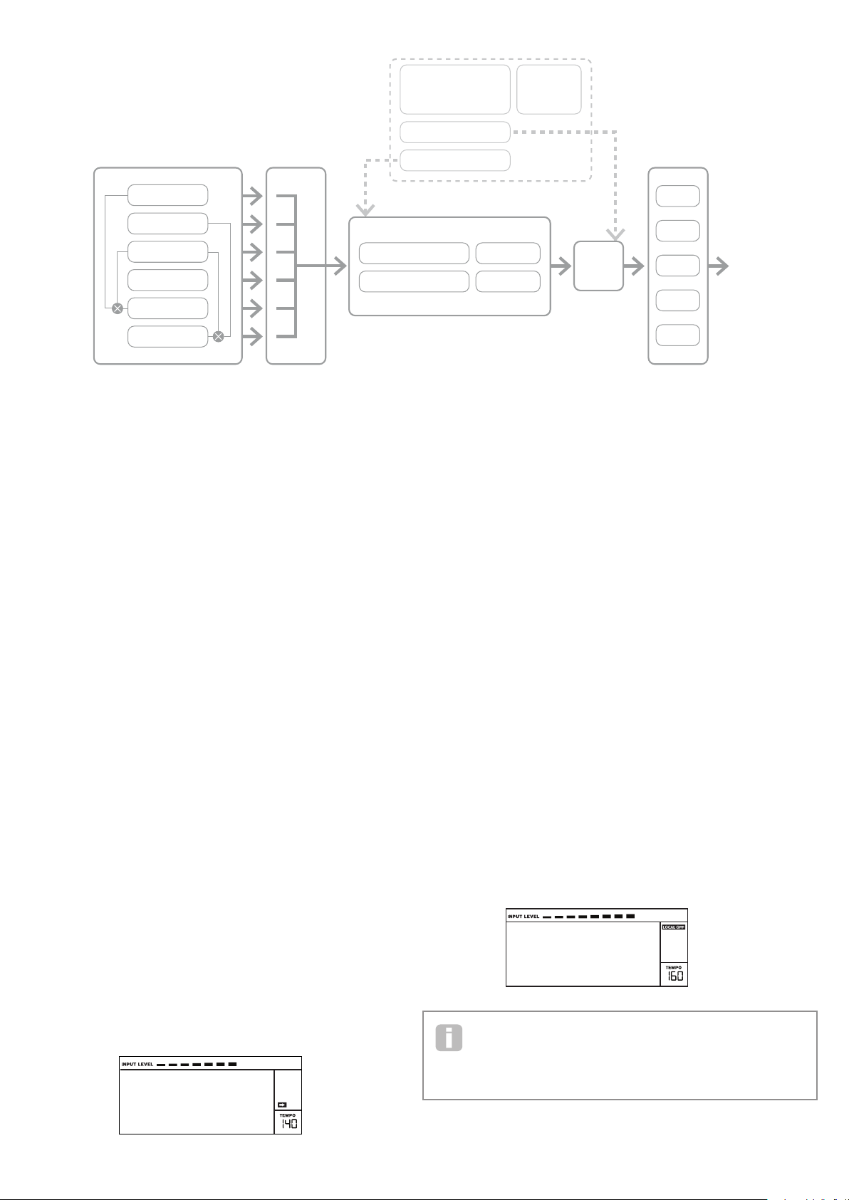
OSCILLATOR 1
FX 1
FX 2
FX 3
FX 4
FX 5
OSCILLATOR 2
OSCILLATOR 3
NOISE
AMP OUT
MIXE R
RING MOD 1*3
RING MOD 2*3
FILTER 1 DISTORTION
FILTER 2 DISTORTION
FILTER 1
FILTER 2
ENVELOPE 1
ENVELOPE 2
ENVELOPES 3 - 6 LFO 1 - 3
SYNTH MENUS –
REFERENCE SECTION
This part of the User Guide gives you a detailed description of every par ameter available
for adjustment in the Mini Nova. As previously explained, all adjustments to p atches – other
than those made via the controls in the Perform and Pads sec tions of the top panel – are
made via the MiniNova’s comprehensive menu structure. The menus also include “System”
or setup options, such as patch dumping, keyboard setup, and so on.
The structure is “context-sensitive” – this m eans that you will be offered a range of options
which is dependent on what it is you are trying to do.
The menu system is a lways ente red by pressing the MENU button [8]. The menu system
consists of six individual menus:
Au dio In
Global
Arp
Chord
Ed it
Dump
Step bet ween the menus with the PAGE I a nd H buttons [7], and press OK [9] to enter the
desired menu. Use the PAGE buttons again to access the parameter you wish to change ;
use the D ATA control [6] to alter the parameter value.
The menu system can be exited by pressing the MENU/BACK button again; otherwise,
it will automatically time-out after a short period, and the screen will revert to display the
currently-loaded Patch information.
NOTE: The Default value s shown for each parameter apply to Initial patche s; other
factor y Patche s will have different value s as part of the Patch definition.
Top Menu: Audio In
Parameter: Input Gain
Displayed as: Inp tGain
Default value: +20 dB
Range of adjustment: -10 dB to +65 dB, O ff
This control adjusts gain for the Audio input. The gain is displayed directly in dBs. As the
gain is increased, the signal at the input will be seen on the bargraph meter at the top of the
LCD display. The ga in should be adjusted so that the meter pe aks two or three segments
below the right-m ost on the loudest passages. The meter also i nclude s an OVER ag; aim
to set your s ignal level so that this never comes on ! Note that if InptGain is set to O ff, the
audio input is inoperative.
Vocoder
Voc/MFX
Parameter: Input FX level
Displayed as: InputFX
Default value: 0
Range of adjustment: 0 – 127
This parameter adjusts the amount of the input signal sent to the F X processor for the
currently selected Patch.
Top Menu: Global
Parameter: Operating System Version
Displayed As: OS Ver
Displays the firmware version cur rently installed in your MiniNova . You may need to
know this in the event of a technical issue arising, or to check whether a newer version is
available from the Novation website.
Parameter: Memory Protection
Displayed As: Protect
Default value: On
Range of adjustment: On, Of f
This is a s afety feature, used to prevent accidental erasure of memories and loss of data.
When set to On, writing Patches or Global data into memory will be prevented, and a
brief warning message ( Memory Protect!) shown on the MiniNova’s display. It
is recommended that Protect is left On unless Patches are being edite d for storing in
memor y, or a System Exclusive dump from a comp uter is to be received.
Parameter: Local Control On/Off
Displayed As: Local
Default value: On
Range of adjustment: On, Of f
This control determine s whether the Mini Nova is to be played from its own keyboard, or
to respond to MID I control from an ex ternal device, such as a MIDI sequencer or master
keyboard. Set Local to On to use the keyboard, and to Off if you are going to control the
synth ex ternally via MIDI or use the MiniNova’s keyboard as a master keyboard. When Off
is selected, a LOCAL OFF flag appears in the LC D display.
Vocoder
Voc/MFX
A primary use of Local C ontrol O n/O ff is to avoid unwante d MIDI loops through
external equipment. When set to Off, the MiniNova’s keyboard and all other controls
still transmit MIDI message s from the M IDI OUT port . If any external equipment is set
to re-transmit M IDI back to the MiniNova, then the synth will still oper ate. This will avoid notes
sounding twice, a reduction in polyphony or any other unpredictable effects.
SIMPLIFIED MININOVA
BLOCK DIAGRAM

13
Parameter: Assign MID I Channel
Displayed As: MIDI Ch
Default value: 1
Range of adjustment: 1-16
The MI DI protocol provides 16 channels allowing up to 16 devices to co- exist on a M IDI
network, if each is assigned to operate on a di fferent MIDI channel. MIDI Ch lets you set
the MiniNova to receive and transmit MIDI data on a particular channel, so that it can
interface correctly with external equipment.
Parameter: Master Fine Tuning
Displayed As: TuneCent
Default value: 0
Range of adjustment: -50 to +50
This control adjusts the frequencies of all the Oscillators by the same small amount,
allowing you to fine -tune the w hole synth to another instrument if necessary. The
increments are cents (1/100 of a se mitone ), and thus setting the value to ±50 tunes
the synth to a quarter-tone midway betwe en two semitones . A setting of zero tunes the
keyboard with the A above middle C at 440 Hz – i.e., st andard Concert Pitch.
Parameter: Key Transposition
Displayed As: Transpse
Default value: 0
Range of adjustment: -24 to +24
Transpose is a very useful global set ting whi ch “shif ts” the whole keyboard one se mitone
at a time up or down. It differs from oscillator tuning in that it modi fies the control data from
the keyboard rather than the actual o scillators. Thus setting Transpose to +4 means that
you can play with other instruments i n the actual key of E major, but only need to play white
notes, as if you were playing in C major.
Parameter: Pot Pickup (Rot ary Per form Cont rol value matching)
Displayed As: PotPckup
Default value: Off
Range of adjustment: On, Of f
Operates with the four rotary PERFORM controls and the F ILT ER knob to match the
parameter value stored in the Patch to the Tweak control’s position. If PotPckup is set On,
the rotary control will have no effect until its level matches that stored in the Patch, thus
avoiding sudden changes in parameter value. Also, the display shows -> Pickup until the
value is reached. With PotPckup set Off, the parameter value will change as soon as the
control is turned.
Parameter: Keyboard Velocity
Displayed As: VelCurve
Default value: Normal
Range of adjustment: Low, Normal, High, Switch, Fixed 4 to 127
Selec ts the MI DI NoteOn Velocit y value which relates the Velocity response of the keys to
the force applied to them as they are played. The values 4 to 127 correspond to the actual
Velocit y values. Normal is the default setting, and should be acceptable for most playing
styles.
Use Low if playing with heavy touch, and High if you have a lighter touch. Switch
is useful for accenting a change in tou ch where a lighter touch will output a velocity
value of 90 and a heavier touch will output a value of 127. Try different curves to
suit your individual playing style(s).
Parameter: Footswitch configuration
Displayed As: FootSwth
Default value: Auto
Range of adjustment: Auto, N /Open, N/ Closed
A sustain footswitch (pedal) c an be connected to the MiniNova via the S US TAIN pedal
socket { 29}. Ascert ain whether your sustain pedal is of the Normally-open or Normally-
closed type, and set this parameter to suit. If you are unsure which it is, connect the
footswitch with the MiniNova unpowered, and then powe r it on (without your foot on
the pedal!) Provided the default setting of Auto is still selected, the polarity will now be
correctly sensed.
Parameter: Clock Source
Displayed As: ClkSo urc
Default value: Internal
Range of adjustment: Internal, USB , MIDI, Auto
The MiniNova uses a master MIDI clock in order to set the tempo (rate) of the arpeggiator
and to provide a time base for synchronisation to an overall tempo. T his cloc k may be
derived internally or provided by an external devic e able to transmit M IDI clock. The
ClkSourc set ting dete rmines whether the MiniNova’s tempo -synchronised features
(Arpeggiator, Chorus Sync, Delay Sync, G ator Sync , LFO Delay Sync, LFO Rate Sync &
Pan Rate Sync) will follow the tempo of a n external MID I clock source or follow the tempo
set by the TEMPO knob [21].
• Internal – the MiniNova will synchronise to the internal MIDI clock irrespective of
what external MIDI clock sources may be present.
• USB – synchronisation will only be set to the external MIDI clock received via
the USB connection. If no clock is detected, the tempo “flywheels”
to the last-known clock rate.
• Midi – synchronisation will only be to an external MIDI clock connected to the
MIDI input socket. If no clock is detected, the tempo “flywheels” to the last-
known clock rate.
• Auto – when no external MIDI clock source is present the MiniNova will default
to the internal MIDI clock. Tempo (BPM) will be that set by the TEMPO knob. If
an external MIDI clock is present the MiniNova will synchronise to it.
When set to any of the ex ternal MIDI clock sources the tempo will be at the MI DI Clock rate
recei ved from the external source (e.g., a sequencer). Make sure the external sequencer i s
set to transmit MIDI Clock. If unsure of th e procedure, consult the sequencer manual for
details.
Most sequencers do not transmit MIDI C lock while they are stopped. Synchronisation of
the MiniNova to MIDI Clock will only be possible while the sequencer is actually recording
or playing. In the absence of an external clock, the tempo will flywheel and will assume the
last known incoming MIDI Clock value.
Parameter: Wheel Illumination
Displayed As: WhelLeds
Default value: On
Range of adjustment: On, Of f
The PITCH and MOD wheels [ 2] are internally illuminated; this setting allows them to be
turned on or off.
Parameter: MiniN ova Power Save
Displayed As: PwrSave
Default value: On
Range of adjustment: On, Of f, 10 mins
This is a n energy-saving option. S etting PwrSave to On will make the MiniNova turn off
(saving the cur rent set tings ) when the computer goes into s leep mode. This only applies if
it is powered via th e USB connection. If set to 10 mins, the keyboard will turn off after that
perio d regardless of how it is powered. In either case, pres sing any key will restore power.
If set to Off, the keyboard will remain on.
Top Menu: Arp
Parameter: Arpeggiator Rate Sync
Displayed As: ArpSync
Default value: 16th.
Ran ge of adju stm ent : See Sync Values table “Sync Values Table” on page 34
This parameter effectively determine s the beat of the arp se quence, based on the current
tempo. See “Parameter: Clock Source” o n page 13.
Parameter: Arpeggiator Gate Time
Displayed As: Arp Gate
Default value: 64
Range of adjustment: 1 to 127
This parameter sets the ba sic duration of the notes played by the Arpeggiator (though
this will be further amended by both the Arp Pttn and Arp Sync settings). The lower the
parameter value, the shorter the duration of the note played. At its maximum value , one
note in the sequence is imme diately followed by the next without a gap. At the default value
of 64, the note duration is exactly half the beat interval (base d on the current tempo), and
each note is followed by a rest of e qual length.
Parameter: Arpeggiator Mode
Displayed As: Arp Mode
Default value: Up
Range of adjustment: See Arp M ode table “Arp Mode Table” on page 38
When enabled, the Arpe ggiator will play all notes held down in a sequence which is
determined by the Arp Mode paramete r. The third column of the table describes the nature
of the sequence in each case.
Parameter: Arpeggiator Oc taves
Displayed As: Ar p Octv
Default value: 1
Range of adjustment: 1 to 4
This setting adds upper octaves to the arp sequence. If Arp Octv is set to 2, the sequence
is played as normal, then immediately played again an octave higher. Higher values of
Arp Octv extend this proc ess by adding additional higher octaves. Arp Octv values
greater than 1 have the effect of doubling, tripling, etc., the length of the sequence. The
additional notes added duplicate the complete original sequence, but octave-shif ted. Thus
a four-note sequence played with Arp Octv set to 1, will c onsist of eight notes when Arp
Octv is set to 2.
 Loading...