

Novation Super Bass Station User Manual
Owners
Manual
ENABLEPROTECT
MAN LFO 2ENV 2
12dB 24dB
OFF ON
1 2 1 2
LFO 1 AND 2 OSCILLATORS 1 AND 2 MIXER FILTER ENVELOPE 1 AMPLIFIER
ENVELOPE 2 FILTER
TRIGGERING SAVESAVE TYPE
WRITE
COMPARE
DATA ENTRY MODEAUDITIONWRITEHEADPHONES SHAPELFO SELECT WAVEFORMRANGE OSC SELECT SOURCE K'YBD TRACK ENV 2 DEPTHOSC 1 - 2 SYNC PWM SOURCE SUB OSC CUT-OFF
PORTAMENTOVOLUME DELAYSPEED SEMITONEDETUNE LFO 1 DEPTHENV 2 DEPTH FREQUENCYLEVEL LFO 2 DEPTHRESONANCEOSC LEVEL
PULSE WIDTH
DECAY SUSTAINATTACK RELEASE
16' 8' 4' 2'
TRI SAWSQRRDM
DEMO
RING EXTNOISE
VELOCITY
PITCH B/ MOD D
PANNING
CV / GATE CH
AT/ BTH MOD
MIDI CLOCK
CHORUS / DIST
ARPEGGIO
TUNING
OSC 1
010010 012
55
50 50
5555
010010010
55
010010010010
010010010010
010
55
010
OFF
1 & 2
OSC 2
010010
DATA
MIDI RX CH
MIDI TX CH
PROGRAM
EDIT WRITE
UTILITY
SAVE

Introduction 1
Front Panel Controls 2
Rear Panel Connections 3
Connections & Setting up 4
Applications - Basic 5
Applications - Advanced 6
Selecting Programs / Finder Mode 9
Editing & Writing Programs / Compare 10
Factory & Restoring Factory Programs 11
About Analogue Synthesis 12
Block Diagram 17
Master Volume Section 18
Data Entry / Program Section 20
Keypad 20
Audition - Auto Trigger Button 21
Mode Button - Program Banks 22
Midi TX & RX Channels 23
Utility Mode / Operation 24
Button 1 Pitch Bend / Mod 24
Button 2 Aftertouch / Breath 27
Button 3 Velocity 31
Button 3 Sound Category 32
Button 4 Chorus 34
Button 4 Distortion 36
Button 5 Arpeggiator 37
Button 6 Panning 42
Button 7 MIDI Clock 44
Button 8 CV / Gate Channel 54
Button 9 Tuning 56
Button 0 Triggering 56
Factory Demo 61
Saving System Exclusive Data Dumps 62
Loading System Exclusive Data Dumps 63
LFO 1 and 2 Section 65
Oscillator 1 and 2 Section 68
Mixer Section 73
Filter Section 75
Envelope 1 and 2 Section 78
MIDI Implementation 80
Controller Map 81
Troubleshooting Guide 82
Specification 83
Ident Map O.B.C.
Table of
Contents

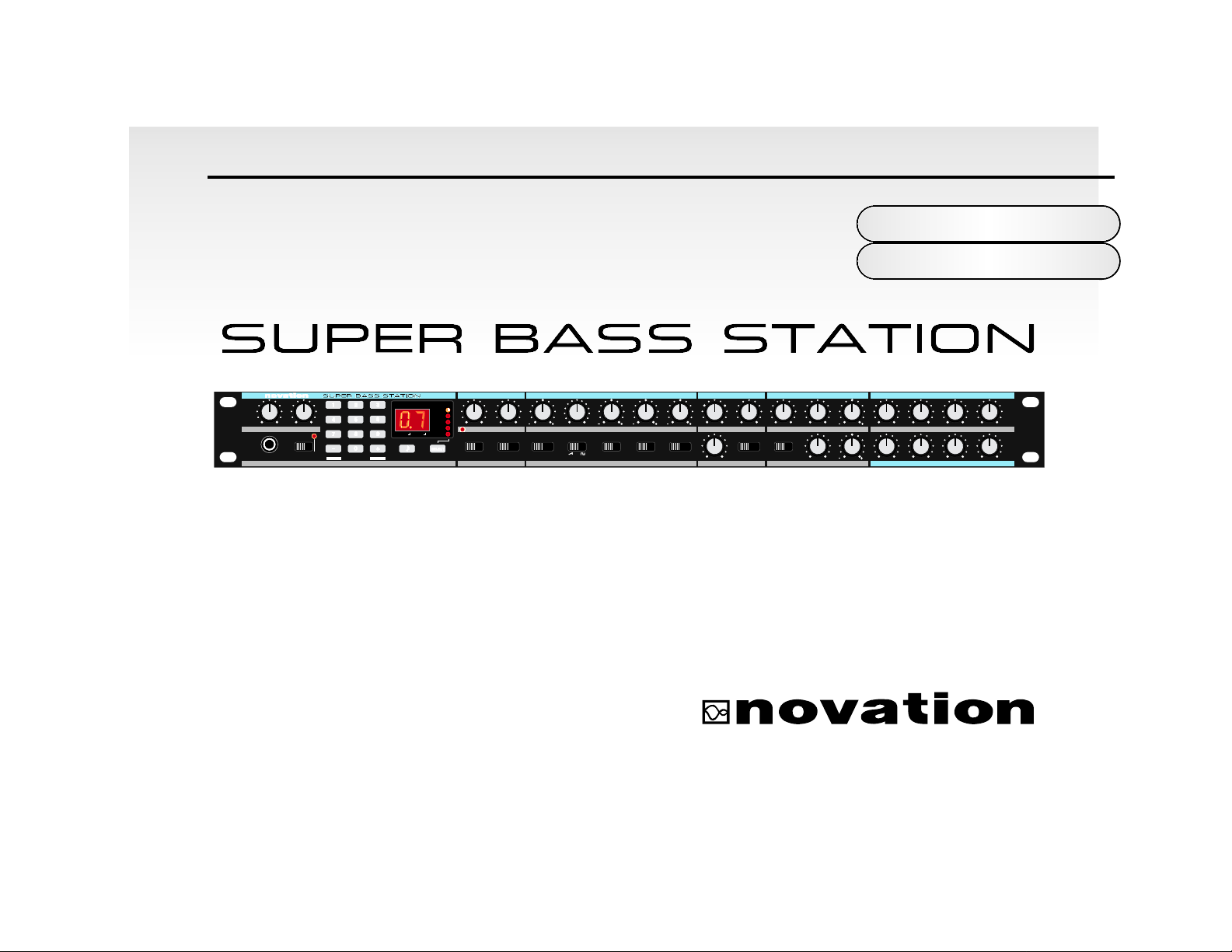
Thank you for buying the Novation Super Bass Station Analogue Synthesiser. The module
you have purchased is ideal for producing the kind of classic synthesised sounds which
have returned to popularity in recent years and features all the Classic methods of Analogue
Subtractive Synthesis.
Based on the award winning BassStation Keyboard and BassStation Rack, the Super Bass Station features Two Main
Oscillators with selectable waveforms plus a new Sub Oscillator that generates deep bottom end and a fatter sound. Like
the BassStation Rack the Super Bass Station also offers Oscillator Sync that allows creation of metallic timbres. ARing
Modulator has been added and there is also a new White Noise Source as well as an External Audio Input for greater tonal
flexibility. The new Mixer Section makes it easy to combine these sources together allowing for the creation of complex timbres. The filters in the Super Bass Station deliver the liquid Sound of Analogue Filters because they are Analogue. They
have been carefully engineered so they retain the character and warmth of classic analogue synthesisers. Selectable, 12db
or 24db, cut-off curves make it easy to faithfully recreate anything from a TB303* to a more traditional synthesiser sound
featuring that liquid resonance that can only be created using analogue technology. With the Super Bass Station the front
panel is self explanatory with every Parameter that is needed having its own knob. All the knobs transmit MIDI Controllers
for easy recording of any movements in real-time on a sequencer and as they are controllers they are easy to edit. Once
“that sound” has been created the Super Bass Station has 150 RAM Program locations to store them in. These plus the 50
ROM programs can be recalled with MIDI Program Change messages.
The Super Bass Station features a built in Analogue Distortion Effect. This can add the edge to harder sounds or at high
levels of drive, can really make a sound scream. Additionally there is a Stereo Analogue Chorus that not only fattens up the
sound but also provides boost to the bottom end. The Super Bass Station also features a Stereo Panner that can be
assigned to LFO’s and Envelopes allowing enhanced dynamic control of the stereo image.
The Super Bass Station is one of the most versatile and creative Analogue Synthesisers available today, with the degree of
MIDI control and accessibility it will deliver “that sound” quickly and easily.
Super Bass Station...Analogue, you are about to hear the difference.
Introduction
Section
1
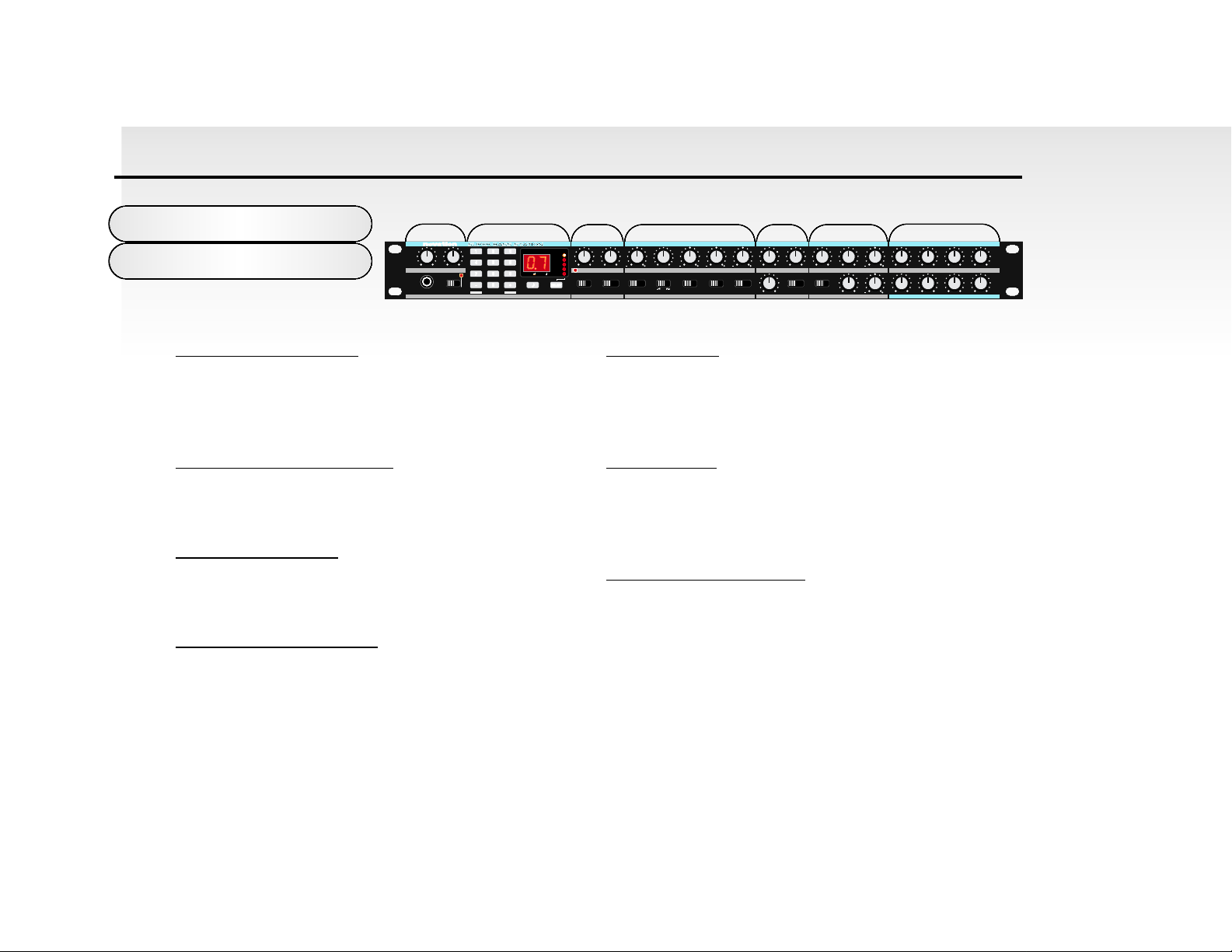
Controls
123 4 56 7
Front Panel
2
1 Master Volume Section
This section contains the Master Volume control,
Portamento / Data Entry control, Headphone output socket
and the Program write switch.
2 Data Entry/Program Section
This section contains the 12 Data Entry buttons, Display
and Menu LED’s, Audition / Demo and Mode select buttons.
3 LFO 1 and 2 Section
This section contains the Speed and Delay controls and the
Shape and LFO select switches.
4 Oscillator 1 and 2 Section
This section contains the Detune, Semitone, ENV2 Depth,
LFO 1 Depth and Pulse Width controls and the Range,
Waveform, Osc Select, Osc 1 - 2 Sync and PWM Source
switches.
5 Mixer Section
This section contains the Osc Level, Noise /
Ring Modulation / External Audio Input Level, Sub Osc
Level controls and the Source switch.
6 Filter Section
This section contains the Frequency, Resonance, LFO 2
Depth, ENV 2 Depth and K’YBD Track controls and the CutOff switch.
7 Envelope 1 and 2 Section
This section contains the Attack, Decay, Sustain and
Release controls for Envelopes 1 and 2.
010010
AT/ BTH MOD
DATA
CHORUS / DIST
ARPEGGIO
PORTAMENTOVOLUME DELAYSPEED SEMITONEDETUNE LFO 1 DEPTHENV 2 DEPTH FREQUENCYLEVEL LFO 2 DEPTHRESONANCEOSC LEVEL
CV / GATE CH
MIDI CLOCK
ENABLEPROTECT
TRIGGERING SAVESAVE TYPE
COMPARE
DATA ENTRY MODEAUDITIONWRITEHEADPHONES SHAPELFO SELECT WAVEFORMRANGE OSC SELECT SOURCE K'YBD TRACK ENV 2 DEPTHOSC 1 - 2 SYNC PWM SOURCE SUB OSC CUT-OFF
MIDI RX CH
MIDI TX CH
PANNING
EDIT WRITE
TUNING
WRITE
010010 012
UTILITY
SAVE
DEMO
1 2 1 2
50 50
16' 8' 4' 2'
TRI SAWSQRRDM
55
5555
LFO 1 AND 2 OSCILLATORS 1 AND 2 MIXER FILTER ENVELOPE 1 AMPLIFIER
PROGRAM
VELOCITY
PITCH B/ MOD D
OFF ON
PULSE WIDTH
MAN LFO 2ENV 2
OSC 1
1 & 2
OSC 2
OFF
010010010
RING EXTNOISE
010
12dB 24dB
010
55
010010010010
DECAY SUSTAINATTACK RELEASE
010010010010
55
ENVELOPE 2 FILTER

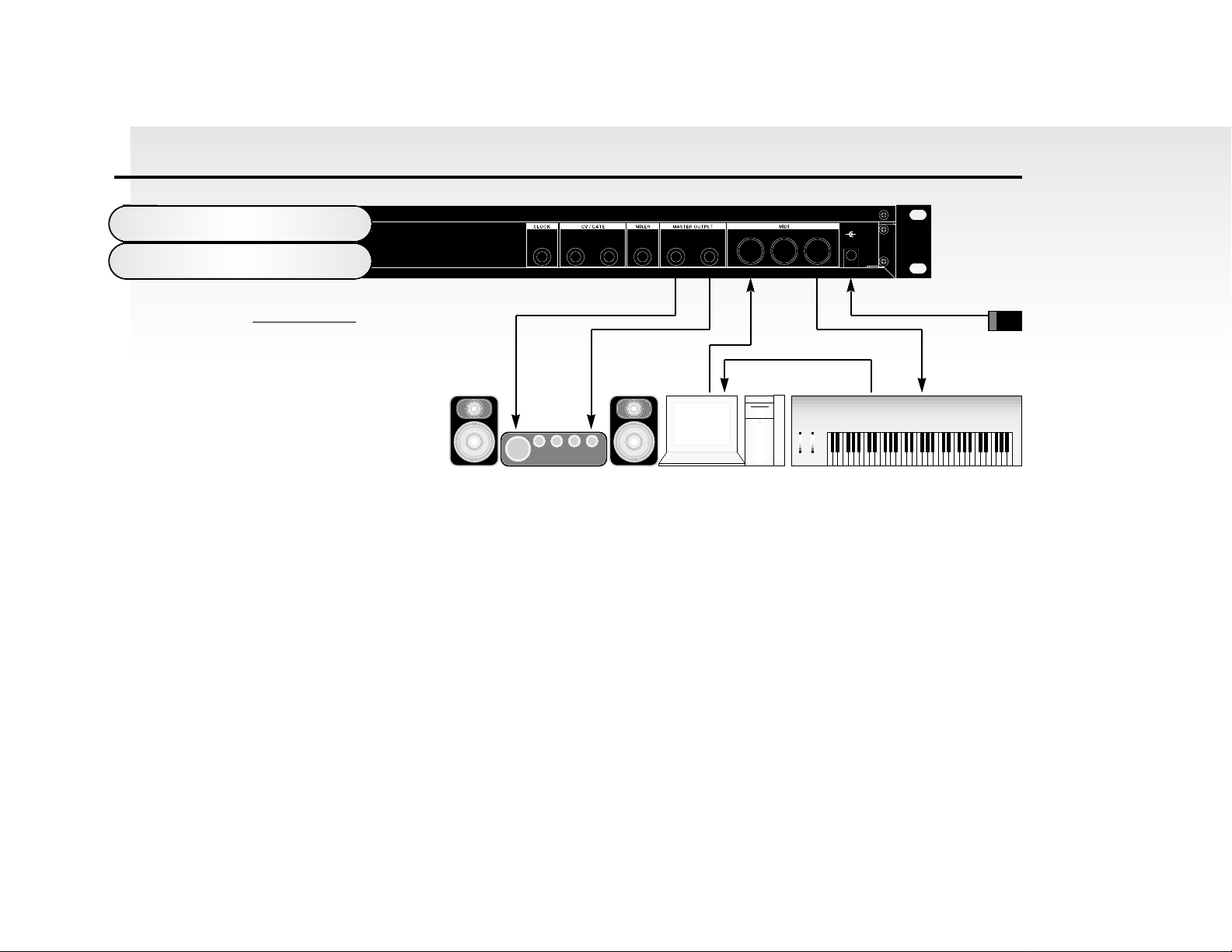
Rear Panel
Connections
3
1 Clock Out
This connector is used to control the Tempo of vintage analogue equipment that utilises analogue trigger pulses. MIDI
Clock, LFO’s or the Arpeggiator can be selected as the master.
2 CV / Gate Outputs
These two connectors are used to interface vintage analogue
equipment that utilise Control Voltage for pitch control and
Gate Pulses for envelope control. MIDI note messages are
converted to CV /Gate and output from these connectors.
3 Mixer External Audio Input
This connector allows external signals to be processed by the
Super Bass Station’s filters and envelopes. External signals
can also be used as triggers for the envelopes.
4 Master Outputs
These connections deliver a stereo line level output signal
for connection to a mixing desk or amplifier.
5 MIDI Connections
IN - This connector is used to receive MIDI Data from an
external device.
OUT - This connector is used to Transmit MIDI Data to an
external device.
THRU - This connector re-transmits MIDI Data received by
the MIDI IN socket to an external device.
6 9V DC Input
Connect the output plug of the AC Adaptor supplied ( PSU-4 )
with the Super Bass Station to this socket.
POWER IN
9V DC
LEFTEXTERNAL
AUDIO INPUT
CV OUT GATE OUT
IN OUT THRU
-
+
RIGHTOUT
BASS SYNTHESISER MODULE
CAUTION: DO NOT OPEN CASE. NO USER SERVICEABLE PARTS INSIDE. REFER TO
QUALIFIED SERVICE PERSONNEL.
This device complies with Part 15 of the FCC Rules. Operation is subject to the following
two conditions: 1.This device may not cause harmful interference. 2.This device must accept
any interference received, including interference that may cause undesired operation.
MADE IN ENGLAND
1234 5 6
POWER IN
9V DC
LEFTEXTERNAL
AUDIO INPUT
CV OUT GATE OUT
IN OUT THRU
-
+
RIGHTOUT
BASS SYNTHESISER MODULE
CAUTION: DO NOT OPEN CASE. NO USER SERVICEABLE PARTS INSIDE. REFER TO
QUALIFIED SERVICE PERSONNEL.
This device complies with Part 15 of the FCC Rules. Operation is subject to the following
two conditions: 1.This device may not cause harmful interference. 2.This device must accept
any interference received, including interference that may cause undesired operation.
MADE IN ENGLAND
Connect the Left and Right sockets of the Super Bass Station to a suitable amplifier or mixing desk’s stereo inputs and
set the “Volume” control on the front panel to a reasonably high output level (9-10). This will maintain a good signal to
noise ratio. Make sure that the input volume setting on your amplifier or mixer is initially set to zero.
Connect the MIDI Out from your master keyboard or sequencer to the MIDI In on the Super Bass Station and check that
the “Write” switch is in the “Protect” position. Now, connect the power supply ( Novation PSU-4 ) to the socket marked
“Power In 9VDC” and plug into a suitable AC power outlet. Switch on the power to the Super Bass Station and the display should now illuminate showing the last selected program number. Now switch on your amplifier and adjust the volume accordingly.
The master keyboard or sequencer will play the currently selected program ( the Super Bass Station is initially set at the
factory to receive on MIDI channel 1). To listen to all the factory preset sounds, first make sure the “Program” LED is on
( if not, use the “Mode” button to re-select ) and then use the “Data Entry” keypad to call up sounds. See page 9
Connections
& Setting up
4
BASIC SETUP
Master Keyboard / Workstation
Novation PSU4
Power Supply
MIDI INMIDI OUT
MIDI INMIDI OUT
Computer / SequencerAmplifer / Mixer and Monitors
Audio Inputs
If you wish to use the Super Bass
Station in MONO, simply use the
left channel output only.

“Selecting Programs / Finder Mode” for more information on selecting sounds. You can also
use the “Audition” button on the front panel to trigger the sounds.
On page 4 is a diagram of the basic way to set up the Super Bass Station .
Normally the setup should be as follows: If the Master Keyboard is a “Workstation” i.e. it has a Synthesiser built in, turn
“Local Off” or the equivalent in its MIDI setup. ( Refer to the manufacturers Owners Manual for details on how to do this. )
Turn the Computer Software / Sequencer’s ‘soft Thru” (or sometimes called “Echo Back”) to the “ON” or “Enabled” position.
Now when selecting a “Track” in the Computer Software/Sequencer that is assigned to the MIDI RX channel of the Super
Bass Station, (Refer: Page 23) playing the keyboard should play the Super Bass Station through the Headphones /
Monitors. Similarly “Tracks” in the Computer Software/Sequencer that are assigned to the MIDI channel(s) of the
“Workstation” should make it produce sound. If not please refer to the Keyboard & Computer Software / Sequencer manufacturers Owners Manuals for details on how to do this.
NOTE: This setup does not allow the recording of knob movements on the Computer Software/Sequencer. This is because
the MIDI output of the Super Bass Station is not connected to the input of the Sequencer/Computer. To record Knob movements in real-time refer Advanced Setup on page 6.
NOTE: If there are additional Keyboards/Modules connected via MIDI as shown, this diagram does not include audio for the
Keyboard/Module. The audio outputs of these devices must also be connected to the mixer.
5
Applications
Basic
POWER IN
9V DC
LEFTEXTERNAL
AUDIO INPUT
CV OUT GATE OUT
IN OUT THRU
-
+
RIGHTOUT
BASS SYNTHESISER MODULE
CAUTION: DO NOT OPEN CASE. NO USER SERVICEABLE PARTS INSIDE. REFER TO
QUALIFIED SERVICE PERSONNEL.
This device complies with Part 15 of the FCC Rules. Operation is subject to the following
two conditions: 1.This device may not cause harmful interference. 2.This device must accept
any interference received, including interference that may cause undesired operation.
MADE IN ENGLAND
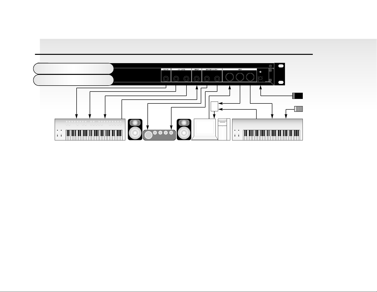
Applications
Advanced
6
This is the advanced way to setup the Super Bass Station and utilises all of the rear panel features. This setup allows realtime recording of knob movements onto the Computer Software/Sequencer as both the MIDI output of the keyboard and
the MIDI output of the Super Bass Station are merged with an external (not supplied) MIDI Merge box. If the Master
Keyboard is a “Workstation” i.e. it has a Synthesiser built in, turn “Local Off” or the equivalent in its MIDI setup. ( Refer to
the manufacturers Owners Manual for details on how to do this. )
Turn the Computer Software/Sequencer’s ‘soft Thru” (or sometimes called “Echo Back”) to the “ON” or “Enabled” position.
Now when selecting a “Track” in the Computer Software / Sequencer that is assigned to the MIDI RX channel of the Super
Bass Station, (Refer: Page 23) playing the keyboard should play the Super Bass Station through the Headphones /
Monitors. Similarly “Tracks” in the Computer Software / Sequencer that are assigned to the MIDI channel(s) of the
“Workstation” should make it produce sound. If not please refer to the Keyboard & Computer Software/Sequencer manufacturers Owners Manuals for details on how to do this.
Master Keyboard / Workstation
Sustain Pedal
Novation PSU4
Power Supply
MIDI INMIDI OUT
MIDI Merge Box
MIDI INMIDI OUT
Computer / SequencerAmplifer / Mixer and Monitors
Audio Inputs
Vintage Analogue Synthesizer
Arp Trigger Input CV IN Gate IN Audio OUT

To use the Super Bass Station’s CV and Gate outputs with older analogue equipment establish which type of interface your vintage equipment has. There are several differing types of
CV and Gate and so you should check in the vintage equipments owners manuals for
details of what standard your equipment is. If this is not available, set as shown in the table
below. This covers most types of CV and Gate variations however there are sometimes slight variation between different
models made by the same manufacturer. You will have to set the MIDI Channel you want the analogue equipment to
respond to and the “type” of CV Gate should also be specified. To do this refer to page 54 “CV / Gate Channel” and page
55 “CV / Gate Type” for details.
Identfor CV / Gate type parameter Manufacturer CV Type Gate Type Range
“00” = Ronald / Arp / Sequential Volts Per Octave +Gate Pulse C0 to C5
“01” = Yamaha / Korg Hertz Per Octave - S/Trig C-1 to C5
“02” = Moog Volts Per Octave +S/Trig C0 to C5
“03” = Ronald / Arp / Sequential Volts Per Octave +Gate Pulse C-1 to C4
“04” = Yamaha / Korg Hertz Per Octave - S/Trig C-2 to C4
“05” = Moog Volts Per Octave +S/Trig C-1 to C4
The Super Bass Station can also have it’s Arpeggiator Latch parameter switched on and off via MIDI. To do so connect a
sustain pedal to the master keyboard. The Super Bass Station reads sustain information as Arpeggiator latch “on” / “off” so
depressing the sustain pedal will switch the Arpeggiator latch “on” and releasing the sustain pedal will switch Arpeggiator
latch “off”. For this to work properly the master keyboard should be transmitting on the same MIDI channel as the RX channel of the Super Bass Station. Additionally this parameter may work in the reverse manner as described if the incorrect
footswitch is connected to the master keyboard. Some master keyboards have the ability to reverse this, refer to the master
keyboards owners manual for details.
7
Applications
Advanced

Alternatively you can control this feature from a sequencer. To do so simply transmit controller 64 with a value of 127 to turn the Arpeggiator latch “on” and transmit controller 64
with a value of 0 to turn the Arpeggiator latch “off” on the same MIDI channel as the RX
channel of the Super Bass Station.
The Super Bass Station can also be used as an effects processor. Feed and external signal into the External Audio Input
and adjust the “Level” rotary in the “Mixer Section” with the “Select Switch” set to “External” and you should hear the external signal from the outputs of the Super Bass Station. If not check the Filter and the “External Auto Trigger Level” and
“Triggering” parameter settings. (refer page 59 and 56 respectively for details ) The Filter allows not only tonal changes to
be made to the sound but resonance can also be applied. Additionally the external signal can be processed by the
Analogue Distortion, Analogue Chorus and the Panner Effects. The Super Bass Station can be set to generate triggers to
run its envelopes from external signals. This is great for making Synthbasses from real Bass signals or Triggering the
envelopes from an external Drum Machine for instance. To do this set the “Level” parameter in Page 3 of Utilities, button 0,
“External Auto Trigger Level” ( refer page 59 for details ) and switch the “Triggering” parameter to “EA”in Utilities, button 0. (
refer page 56 for details ) The “External Auto Trigger Level” parameter controls how loud an external signal has to be
before the external signal will trigger the envelopes. The range is to “01” to “99”. The number indicates the “Trigger
Threshold Level”, the higher the value the louder the external signal has to be before triggers are generated. The
“Triggering” controls how the envelopes are triggered. In the most of the range the envelopes are triggered by incoming
MIDI note data. If this parameter is set “EA” then incoming MIDI note data does not trigger the envelopes, the external signal does.
NOTE: This function works independently from the “Level” control in the mixer section.
NOTE: If you have the “Triggering” set to “EA” no sound will be heard when MIDI notes are sent to the Super Bass Station
until an external signal connected to the external signal input goes past the trigger level set with this parameter. If no external signal is present or connected and this parameter is set to “On” no sound will be heard when MIDI notes are sent to the
Super Bass Station.
Applications
Advanced
8

There are three ways to select a program. First make sure you are in the “Program Mode”.
The “Program Mode” is selected if the “Program LED” is lit or flashing. If it is not press the
MODE button until it is. There are 2 “Banks” of 100 sounds in the Super Bass Station. They
are divided up as follows: You cannot store programs in the ROM area (“A” Bank 000 - 049)
only in the RAM area.( “A” Bank 050 - 099 and “B” Bank 100 - 199) If you edit a ROM program, you can save it in one of
the 150 RAM user program locations. There are three methods in which you can select a Program :
1. DIGIT INPUT Using the buttons 0 to 9. NOTE: this must always be a three digit entry, for example :
To select Bank A sound 8, press the “0” and “0” and “8” buttons and the display reads “08” and the “Program” LED is
continuously lit
indicating that you are in Abank.
To select Bank B sound 17, press the “1” and “1” and “7” buttons and display reads “17” and the “Program” LED is flashing
indicating that you are in B bank.
2. INCREMENT/DECREMENT Using the “-” and “+” buttons.
Press the “+” button to move up to the next program. Press the “-” button to move down to the next program. You will notice
that if program Abank 99 is selected and press the “+” button the program will change to B bank 00.
You can also use MIDI Program Change and Bank Change commands from a sequencer or other external MIDI device to
call up programs.
3. FINDER MODE Performing a search for similar sounds.
Pressing the “Audition / Demo” will not only activate the Demo for the category of the sound currently selected but also will
engage “Finder Mode”. As an indication that the Super Bass Station is in “Finder Mode” both the Decimal points in the display flash. Pressing the “+” and “-” buttons while in “Finder Mode” will not move up or down to the next program but up or
down to the next program in the same category. This makes it easy to audition similar sounds without having to remember
all the sounds locations. i.e if a”Bass” category sound is selected then pushing “+” will advance to the next “Bass” category
sound. To return to normal operation press the Audition / Demo button again. See Utilities / Sound Category on page 32 for
more information on categories and the separate sheet for more information on the Factory sounds.
Selecting Programs
9
“Finder” Mode

Editing a Program
To change or “Edit” a program, simply adjust the parameters you wish to alter. The Edit LED on
the display will flash to show that you are no longer listening to the stored program. If you do not
store this new edit before calling up another program it will be lost.
Writing a Program into Memory
The program memory on the Super Bass Station is divided up as follows: You cannot store programs in the ROM area (“A”
Bank 000 - 049) only in the RAM area.( “A” Bank 050 - 099 and “B” Bank 100 - 199) If you edit a factory program, you can
save it in one of the 150 user program locations. To store a new or edited program, move the “Write” switch to the “Enable”
position and the “Enable LED” flashes. Now, using the “Data Entry” buttons ( “0” to “9” only ) select the program number
where you want to store the program. Remember this is a three digit entry, “050” to “199” ( “000” to “049” are ROM ) To
store the program in the same location simply press the “WRITE” button. If you want to listen to a program before overwriting it use the Compare function.
Using the Compare Function
When you have edited a program, move the “Write” switch to the “Enable” position and the “Enable LED” flashes. Press the
“COMPARE” button once and the “Edit” LED will flash at a faster rate to indicate “Compare” mode is active. You can now
listen to the original program before deciding whether you want to overwrite it or not. Check the program using an external
keyboard / computer or the “Audition” button on the front panel. Pressing the “COMPARE” button again will bring back the
edited program. If you do want to save the program in this location, press the “WRITE” button and the “Write” LED on display panel flashes momentarily. If you don”t want to save the program in this location you can choose another by simply
10
About Editing/
Writing/Compare

entering any program number from “050” to “099” in the “A” Bank and “100” to “199” in the
“B” Bank using the “Data Entry” keypad buttons “0” to “9”.
NOTE: In this mode the “-” and “+” Buttons cannot be used.
Once again, you can check the programs using the “COMPARE” feature and then, when you have found a suitable loca-
tion, press the “WRITE” button. The program is now saved.
Note 1: Always return the “WRITE” switch to the “Protect” position after completing a save operation. This will avoid any
accidental erasure of programs. The “Write” LED will flash to warn you of the “Enabled” state.
Note 2: Programs can only be saved in the User locations (“050” to “099” in the “A” Bank and “100” to “199” in the “B”
Bank). If you attempt to save a program into any of the Factory ROM locations ( “000” to “049” in the “A” Bank ) the display
digits will flash rapidly to warn that this operation cannot be competed.
Factory Programs
The Super Bass Station comes pre loaded with 200 sounds. The first 50 in the “A” bank are ROM sounds ( Read Only
Memory ) and these cannot be erased. All the other sounds in banks “A”and “B” are in RAM and can be overwritten or
erased. The Super Bass Station can “Recall” all these sounds, reloading the factory sounds into the RAM. You can do this
at any time simply by switching the power off and pressing the “Save” and the “Write” buttons simultaneously and while
holding them down switch the power to the Super Bass Station back on. This will reload all the factory sounds.
NOTE: Doing this will erase permanently any sounds that are in the Super Bass Station and replace them with the factory
sounds. To “Save” any special sounds you might have made refer to Mode 5 - Save System Exclusive Data Dumps on
page 62.
About Compare/
Factory Programs
11
To understand synthesis of sound it is necessary to have some understanding about sound
itself. Sound is a vibration or Oscillation. These vibrations create changes in air pressure
that is picked up by our ears and perceived as sound. When dealing with musical sounds
the vibrations or oscillations occur at regular intervals and are perceived as the “Pitch” or
“Frequency” of a sound. The simplest musical sound is a sine wave because it contains only one “Pitch” and is perceived
as a very “Pure” tone, similar to a whistle. Most musical sounds consist of several different “Pitches” or “Frequencies” The
loudest is referred to as the “Fundamental Harmonic” and determines the perceived “Pitch” of the note. The other frequencies present are called “Harmonics” and in musical sounds usually occur in multiples of the fundamental harmonic’s frequency, i.e. If the fundamental note is 440Hz then a musical harmonic series would be, 2nd Harmonic = 880Hz, 3rd
Harmonic = 1320Hz, 4th Harmonic - 1760Hz, 5th Harmonic = 2200Hz etc. etc. The number and loudness of these
“Harmonics” determine the “Timbre” of a sound. This gives a sound character and is why a violin sounds different from a
guitar and a piano sounds different again. In an Analogue synthesiser you have the choice of several different waveforms.
Each waveform has different amounts of harmonics and so the “Timbre” of each one is quite different. Below are descriptions of some of the waveforms and indications on what they can best be used for.
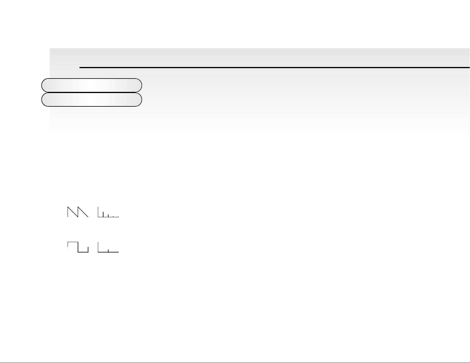
Sawtooth waves have all the harmonics of the fundamental frequency. As you can see every harmonic has half the amptitude of the previous one. This waveform is pleasing to the ear and is useful
for Basses, leads and synthesising stringed instruments.
Square waves have only the odd harmonics present. These are at the same amptitude as the odd
harmonics in a saw wave. Square waves have a hollow / metallic sound to them and so are useful
for creating unusual synthesiser sounds and oboe like sounds.
12
About Analogue
Synthesis
Sawtooth Wave
Volume
Harmonic
12345
Square Wave
Volume
Harmonic
12345
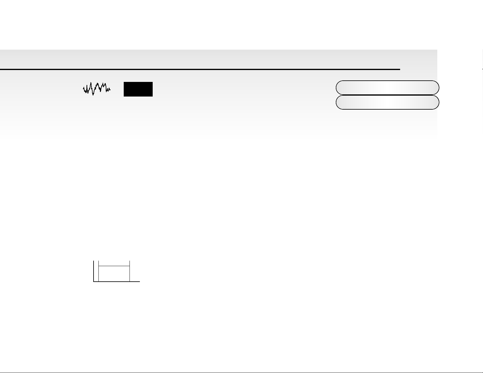
White noise has no fundamental and all frequencies are at the
same level. This waveform can be used by itself to synthesise
explosions or wind and when used in conjunction with other
waveforms can be used to create the illusion of “Breath” in an instrument.
The choice of waveform is important because it determines the basic “Timbre” of the sound you are making. Once the
waveform has been selected you can then “fine tune” the harmonic content of a sound by passing it through a “Filter” to
remove any unwanted harmonics. The filter in an Analogue synthesiser is a very powerful “Tone Control”. Like the tone controls on a stereo, the filter can alter how things sound but cannot change the style of music being played on the CD, and so
the filter in a synthesiser can alter the “tone” of a sound but is restricted by the basic “Timbre” of the waveform. For this reason in most Analogue synthesiser's, several waveforms are available at once and it is possible to “mix” them together to
provide more harmonically rich waveforms.
The last major feature that is important when synthesising sound is “Volume”. The “Volume” of sounds vary as time goes by
and so an Organ has a very different volume characteristic than that of a Piano or a String section. See the diagrams below
for details.
An “Organ” can be seen to go to full volume instantly when a key is pressed and then stays at full volume until the key is
released, at which point the volume drops instantly to zero.
13
About Analogue
Synthesis
Noise
Volume
Harmonic
12345
Key "On" Key "Off"
Time
Volume
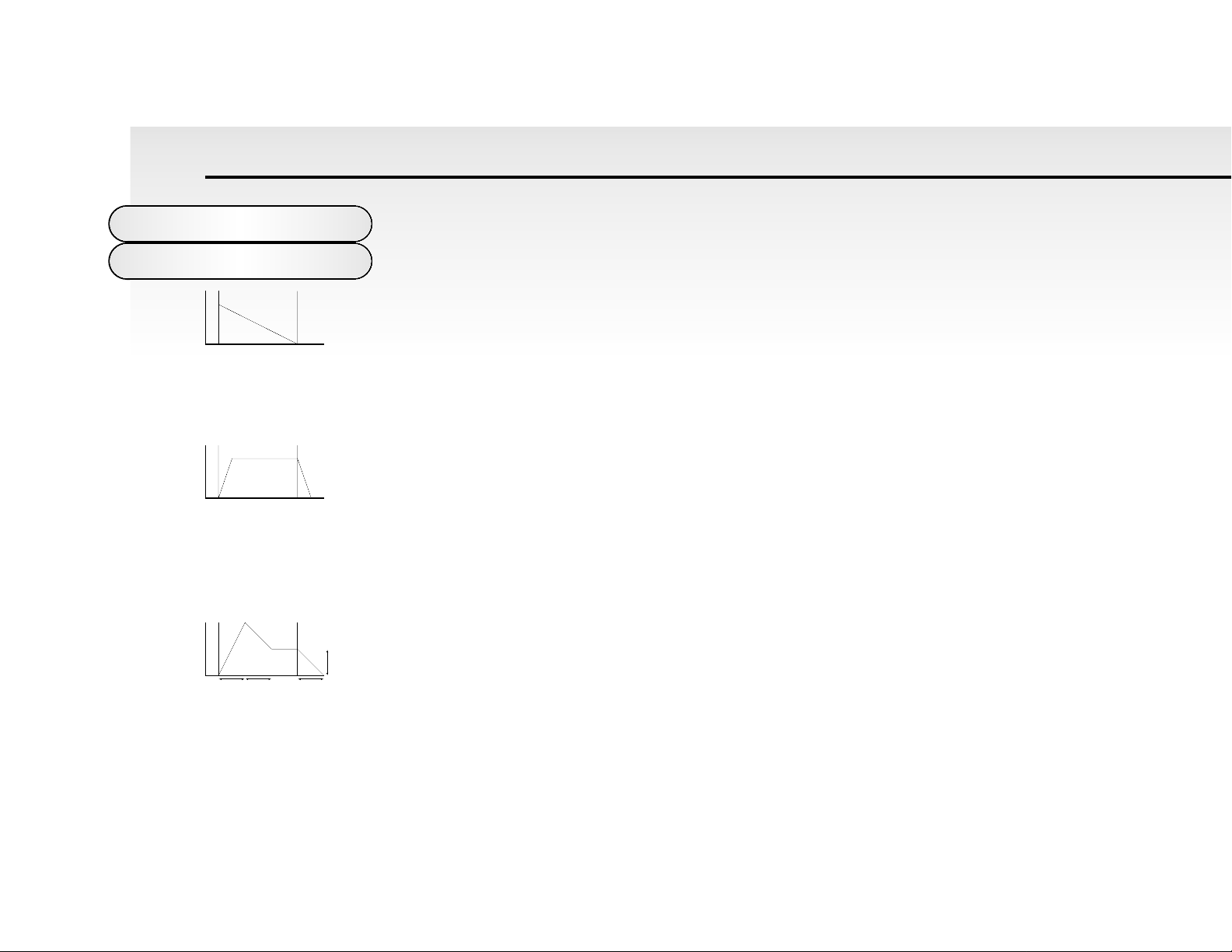
A“Piano” can be seen to go to full volume instantly when a key is pressed and then gradual-
ly falls back down to zero after several seconds.
A“String Section” can be seen to go to full volume gradually over several seconds when a key is pressed and then stays
there until the key is released when gradually over a couple of seconds the volume drops to zero.
These curves are called “Envelopes” and in an Analogue synthesiser “Envelope Generators” are used to recreate them.
The “Envelope Generators” are connected to an amplifier, which controls the “Volume” of the sound.
Envelope Generators have 4 parameters that are used to adjust the shape of the envelope. Refer to the diagram below.
14
About Analogue
Synthesis
Key "On" Key "Off"
Time
Volume
Key "On" Key "Off"
Time
Volume
Attack
Decay Release
Sustain
Key "On" Key "Off"
Time
Volume

A= Attack time. This is used to adjust the time it takes when a key is pressed for the envelope to go from zero to full value and can be used to create “Fade in’s”.
D = Decay time. This is used to adjust the time it takes for the envelope to go from full value
to the value set by the Sustain level.
S = Sustain level. This is used to set the level that the envelope remains at while the key is held down.
R = Release time. This is used to adjust the time it takes when key is released from the Sustain level to zero and can be
used to create “Fade out’s”.
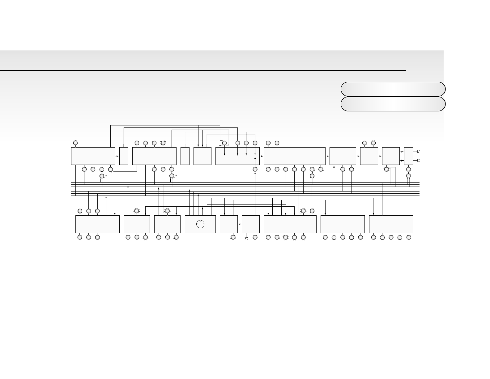
An Analogue synthesiser can be broken down into three main elements.
1 The Oscillator generates “Waveforms” at a certain “Pitch”.
2 The type of “Waveform” selected and the settings of the “Filter” determines the sounds “Tone”
3 The sound is then passed through an “Amplifier” that is controlled by an “Envelope Generator”. These alter the
“Volume” of a sound over time.
All of these main elements can be further manipulated by various methods. For example:
The “Pitch” of a note can of course be played on a keyboard on a synthesiser but additionally it can be manipulated in real
time using the “Pitch Bend Wheel” to create “Slides” and “Bends” in pitch.
“LFO’s” ( Low Frequency Oscillators ) can be used to “Wobble” the pitch of a note at a specific rate creating a “Vibrato”
effect.
The “Filter” can be manipulated by “LFO’s” to vary the “Tone” of a sound at a specific rate creating a “Wah Wah” type of
15
About Analogue
Synthesis

effect. An “Envelope Generator” can also be used on the filter so that the “Tone” of a sound
varies over time. AFeature called “Keyboard Tracking” can also be used on the filter so that
the “Tone” of a sound changes depending on the note being played.
The Amplifier can be manipulated by “Envelope Generators” so that changes in the “Volume” of a sound over time can
make a sound short and percussive or more like a piano or organ. Additionally the “Velocity” at which you hit the keys can
also be used to manipulate the “Volume” of a sound making the sound more “expressive”.
Parameters that manipulate these three main elements are called “Modulators”
The best thing to do is to just get in there and tweak the knobs, after all that’s what we put them there for. Experiment and
you will soon be creating your own sounds. Do not worry about erasing the Factory sounds in the memory, if you want the
factory sounds can be recalled at any time. Refer to page 11 for details.
16
About Analogue
Synthesis
Saw Sq
Saw Sq
Detune Semi
Range
Osc 1&2 Mix
Sub
Noise Ring
External Audio
Cutoff
Reso
Drive On Off
LFO 1 ENV 2
PWM
PWM Source
Oscillator Sync On/Off
LFO 1 ENV 2
PWM
PWM Source
ENV 2 LFO 2 CC1 AT Breath
24/12db
Tracking
AT Breath Chorus Mod Source
Depth
Pan Mod Source
Line Output
Panner
Stereo Analogue
Chorus
Analogue Distortion
Voltage Controlled Amplifier
Voltage Controlled FilterMixer Section
Ring Modulator
Noise
Source
Oscillator 2Sub OscOscillator 1
CC1
AT
Breath
Pitch Controller
Porta
PB Range
Tune
Sync
Speed Delay Waveform
Sync
Speed Delay Waveform
MIDI Clock IN
MIDI Clock IN
MIDI
LFO 2
LFO 1
CC1
Clock
Pitch
Gate
Trigger Controller
Trigger Type
External Audio
Level Sensor
External
Audio IN
Threshold
Arpeggiator
Sync On Off
Speed Latch
Keysync
Range Pattern
ENV 1
Attack Decay Sustain Release Velocity
ENV 1
Attack Decay Sustain Release Velocity
÷ 2
Pitch IN
MIDI Clock IN
AT
Breath
Pitch
Gate Gate Gate IN
Gate IN
Block
Diagram
17
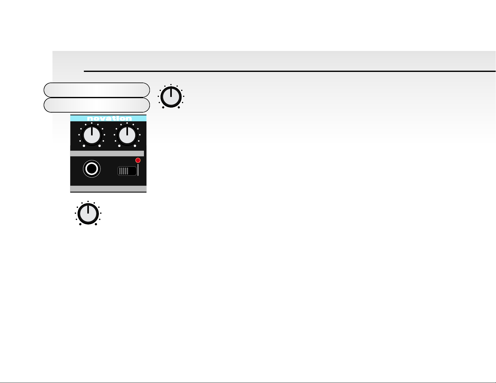
Volume - Rotary
This knob adjusts the overall output volume of the Super Bass Station on both the Main L/R
and Headphone outputs.
NOTE: This control can be overridden by MIDI Volume data. If a MIDI Volume of “0” has been
received by the Super Bass Station, no output will be heard regardless of the position of this
knob. To reset the volume either transmit the relevant MIDI Volume level or move the Volume
knob - this automatically overrides the MIDI setting.
Portamento / Data - Rotary
This knob adjusts the Portamento effect in the Program mode and functions as a data entry knob in the Utility mode. In the
Program mode notes jump instantly from one pitch to another when this knob is set to 0. Turning the knob clockwise brings
in the Portamento effect and notes will smoothly glide from one pitch to the next. In the Utility mode values of parameters
are set with this knob.
Master Volume
Section
18
ENABLEPROTECT
WRITEHEADPHONES
PORTAMENTOVOLUME
010010
DATA
VOLUME
010
PORTAMENTO
010
DATA
Write - Switch
This switch protects your programs from accidental erasure. During normal operation it should be left in it’s “Protect” position however, when you have edited or created a new program that you want to save, moving it to the “Enable” position will
allow you to “write” over an existing program. Refer: “Writing a Program Into Memory” on page 10.
Headphone - Socket
Use this 1/4 jack socket to monitor the output of your Super Bass Station via headphones. This output will drive any type of
headphones.
Master Volume
Section
19
ENABLEPROTECT
WRITE
HEADPHONES

This is where you select the programs on the Super Bass Station, set the MIDI transmit and
receive channels, set the various utility functions and store newly edited programs.
Data Entry Keypad - Buttons
The 12 buttons of the calculator style “Data Entry” keypad are used to
call up and set the various operating parameters of each “Mode”. In
the, “MIDI RX Channel”, MIDI TX Channel”, “Utility” and “Save” Modes
the operation of these buttons are different from the “Program Mode”.
In these modes they work as follows :
You can use two methods to enter a number :
1. DIGIT INPUT - using the buttons 0 to 9.
NOTE: In the MIDI RX, MIDI TX, Utility and save modes this must always be a two digit entry, for example :
To select a value of 8 —— press the “0” and “8” buttons - display reads “08”.
To select a value of 17 —- press the “1” and “7” buttons - display reads “17”.
2. INCREMENT/DECREMENT - using the “-” and “+” buttons.
Press the “+” button to move up to the next value.
Press the “-” button to move down to the next value.
These buttons can also be used to “scroll” through values by pressing and holding down until the desired value is reached.
Data Entry/Program
Keypad
20
TRIGGERING SAVESAVE TYPE
WRITE
COMPARE
DATA ENTRY MODEAUDITION
DEMO
VELOCITY
PITCH B/ MOD D
PANNING
CV / GATE CH
AT/ BTH MOD
MIDI CLOCK
CHORUS / DIST
ARPEGGIO
TUNING
MIDI RX CH
MIDI TX CH
PROGRAM
EDIT WRITE
UTILITY
SAVE

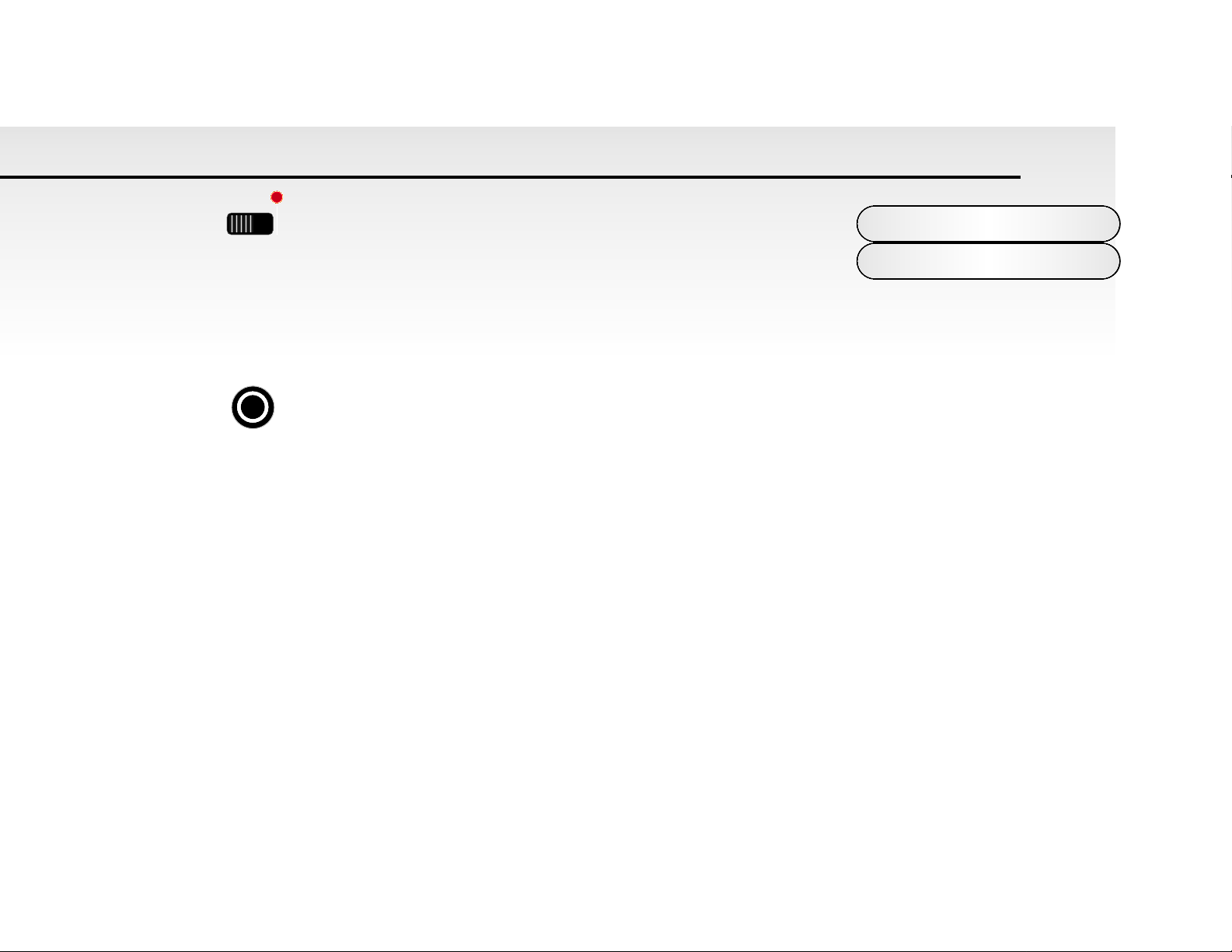
Audition / Demo - Button
This button is used to trigger the currently selected program. It provides a convenient way of monitoring a sound whilst
working at the control panel.
AUDITION
When in Program mode press the Audition / Demo button to start a small demo of the currently selected sound.
There is a different demo for each sound category. For more information on categories refer to page 32.
FINDER MODE Performing a search for similar sounds.
Pressing the “Audition / Demo” will not only activate the Demo for the category of the sound currently selected but will also
engage “Finder Mode”. As an indication that the Super Bass Station is in “Finder Mode” both the decimal points in the display flash. Pressing the “+” and “-” buttons while in “Finder Mode” will not move up or down to the next program but up or
down to the next program in the same category. This makes it easy to audition similar sounds without having to remember
all the sounds locations. i.e if a”Bass” category sound is selected then pushing “+” will advance to the next “Bass” category
sound. To return to normal operation press the Audition / Demo button again. See Utilities / Sound Category on page 32 for
more information on categories and the separate sheet for more information on the Factory sounds.
DEMO
When in the Utility mode press the Audition / Demo button to start the Factory Demonstration. This is a montage of all the
sound categories individual demo’s strung together. Once started this demo will run in a loop continuously. Pressing this
button again will stop the demonstration.
Data Entry/Program
Audition/Demo
21
AUDITION
DEMO

MODE - Button
This button is used to select which of the five main parameter “Modes” are accessed by the
“Data Entry” keypad. The current mode is indicated by one of five LED’s on the right hand side of the display panel.
NOTE: When the Super Bass Station is switched on, “Program” mode is automatically selected. Each time the Mode button
is pressed the next “Mode” in the menu will be selected i.e. “Program”, “MIDI RX Channel”, “MIDI TX Channel”, “Utility” and
“Save”. From “SAVE”, the next press will loop the menu back to the Program Bank Amode.
MODE 1 - Program Bank A & B.
There are 2 “Banks” of 100 sounds in the Super Bass Station. They are divided up as follows: You cannot store programs in
the ROM area (“A” Bank 000 - 049) only in the RAM area.( “A” Bank 050 - 099 and “B” Bank 100 - 199) If you edit a ROM
program, you can save it in one of the 150 RAM user program locations. The “Program Mode” is selected if the “Program
LED” is lit or flashing. If it is not press the MODE button until it is. The “Data Entry Keypad” works differently in this mode.
There are two methods to enter a number :
1. DIGIT INPUT Using the buttons 0 to 9. NOTE: this must always be a three digit entry, for example :
To select Bank A sound 8, press the “0” and “0” and “8” buttons and the display reads “08” and the “Program” LED is
continuously lit
indicating that you are in Abank.
To select Bank B sound 17,press the “1” and “1” and “7” buttons and display reads “17” and the “Program” LED is flashing
indicating that you are in B bank.
2. INCREMENT/DECREMENT Using the “-” and “+” buttons.
Press the “+” button to move up to the next program. Press the “-” button to move down to the next program. You will notice
that if program Abank 99 is selected and press the “+” button the program will change to B bank 00.
You can also use MIDI Program Change and Bank Change commands from a sequencer or other external MIDI device to
call up programs.
Data Entry/Program
Mode/Banks
22
MODE
SELECT

NOTE : Because the Super Bass Station’s program numbers start at “000” the next higher
number must be used via MIDI program change to call up the correct sound. i.e. 019 on the
Super Bass Station = MIDI program change 20.
MODE 2 - MIDI Receive Channel
This is where you set the MIDI receive channel for the Super Bass Station . Use the “Mode” button to select the “MIDI RX
Ch.” mode - LED on, and then the “Data Entry” keypad to enter your selection. The recognised numbers in this mode are
from “01” to “16”. NOTE: the “MIDI RX CH.” LED will flash when MIDI data is received on this channel.
MODE 3 - MIDI Transmit Channel
This is where you set the MIDI transmit channel for the Super Bass Station . Use the “Mode” button to select the “MIDI TX
Ch.” mode - LED on, and then the “Data Entry” keypad to enter your selection. The recognised numbers in this mode are
from “01” to “16”. NOTE: The MIDI TX and RX channel settings are memorised when the power is turned off.
MODE 4 - Utility
This is the section were Global and some Sound Parameters are edited.
The various Parameter groups are selected by pressing the appropriate button on the twelve key pad when in the utilities
mode. Pages exist within these Buttons and they are selected by pressing the appropriate button again. Once the desired
page is selected the ident flashes between the ident of the parameter selected and it’s value. To change the value of any
parameter use the “Data Entry / Portamento” Rotary control. Fine increments of parameters values can be set using the
“-” and the “+” Buttons.
Data Entry/Program
MIDI/Utilities
23
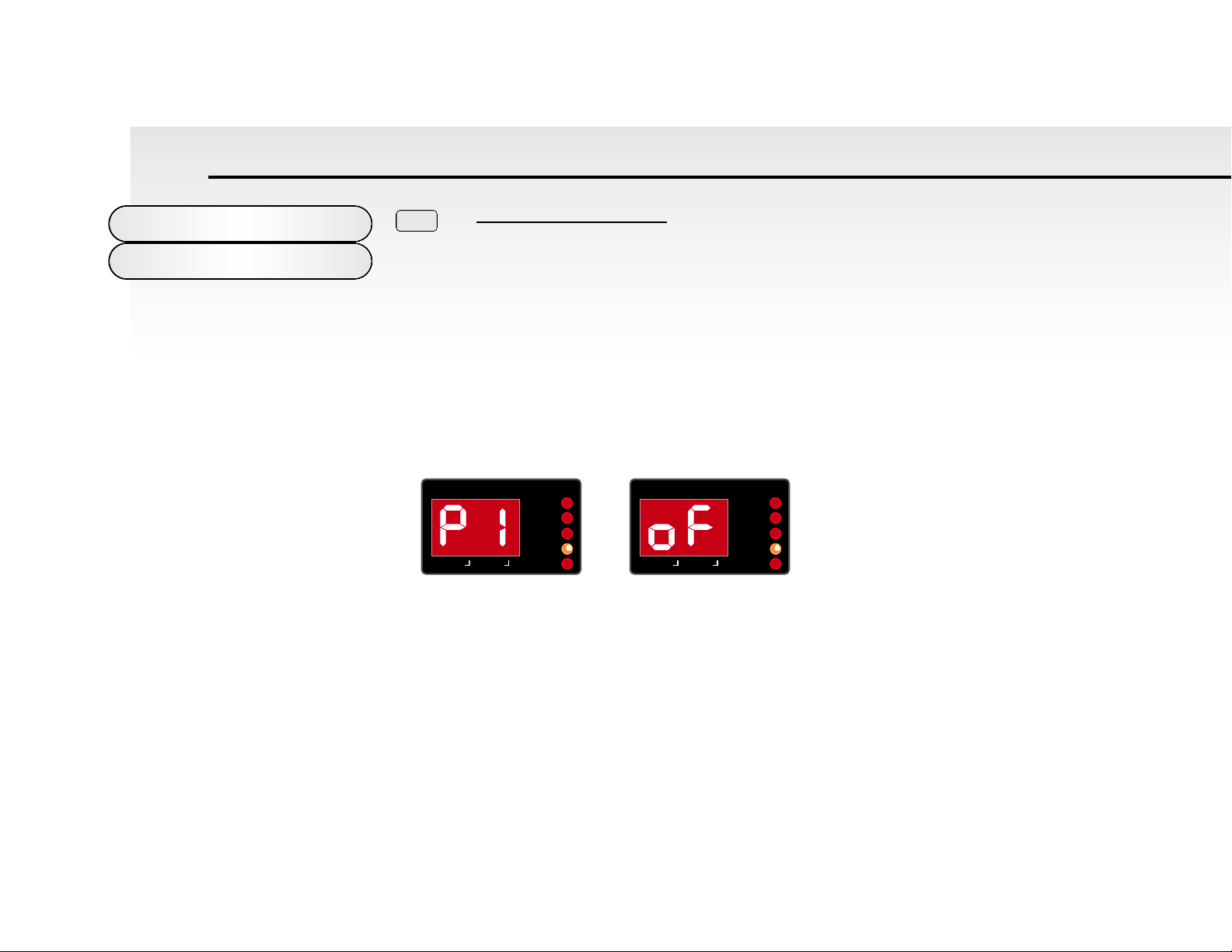
Button 1 - Pitch B / Mod D
Related groups of parameters are in “Pages” within each button. This buttons parameters are used to determine how the
Pitch Bend Joystick / Wheel on your controller keyboard effects the pitch of the oscillators.
Pages exist within this button and they are selected by pressing button 1 again. Refer to the Ident Map on the outside back
cover of this manual for more details. To change the value of any parameter use the “Data Entry / Portamento” Rotary control. Fine increments of parameters values can be set using the “-” and the “+” Buttons.
Page 1 - Oscillator 1 Pitch Bend Range
Ident Value
This display will alternate between “P1” ident ( Oscillator 1 Pitch Bend Range ) and it’s value. Use the Data Entry /
Portamento Rotary control to adjust the value of this parameter. This parameter controls the pitch bend range of oscillator 1
with the Joystick/Wheel on your controller keyboard for the current program selected. The range is “oF” to “12”. This is in
semitones. “oF” = no change and “12” = twelve semitone range for oscillator 1.
This parameter is memorised with the program.
DataEntry/Program
Utilities/Pitch/Mod
24
PITCH B/ MOD D
1
MIDI RX CH
MIDI TX CH
PROGRAM
EDIT WRITE
UTILITY
SAVE
MIDI RX CH
MIDI TX CH
PROGRAM
EDIT WRITE
UTILITY
SAVE

Page 2 - Oscillator 2 Pitch Bend Range
Ident Value
This display will alternate between “P2” ident ( Oscillator 2 Pitch Bend Range ) and it’s value. Use the Data Entry /
Portamento Rotary control to adjust the value of this parameter. This parameter controls the pitch bend range of oscillator 2
with the Joystick/Wheel on your controller keyboard for the current program selected. The range is “oF” to “12”. This is in
semitones. “oF” = no change and “12” = twelve semitone range for oscillator 2.
This parameter is memorised with the program. Having independent control over the pitchbend range on each oscillator
means that you have greater control over sync sounds and allows interesting effects to be produced when using the pitchbend Joystick/Wheel. For normal operation you must set both oscillators to the same range.
Page 3 - Oscillator 1 and 2 Pitch Mod Depth
Ident Value
This display will alternate between “Pd” ident ( Oscillator 1 and 2 Pitch Mod Depth ) and it’s value.
Data Entry/Program
Utilities/Pitch/Mod
25
MIDI RX CH
MIDI TX CH
PROGRAM
EDIT WRITE
UTILITY
SAVE
MIDI RX CH
MIDI TX CH
PROGRAM
EDIT WRITE
UTILITY
SAVE
MIDI RX CH
MIDI TX CH
PROGRAM
EDIT WRITE
UTILITY
SAVE
MIDI RX CH
MIDI TX CH
PROGRAM
EDIT WRITE
UTILITY
SAVE
 Loading...