

Novation Nova II User Manual
levelsolo
copy
menu
mix
pitch
width
sync
lfo 1
lfo 2
env 2
env 3
menu
square saw special
osc 1 osc 2 osc 3 noise1*3 2*3
fm fm fm
menu
constant
gate
pan
config
level/balance
vocoder
reverb chorus
copy distort/eq
delaymenu bypass
23456
menu
multi trigger
env 3
env 1
(amp) env 2
overload
(poly limit)
lfo 1 lfo 2menu
square saw tri s/h
menu 12db
low
18db 24db
band
high
freq
lfo 1
lfo 2
env 2
env 3
master volume
octave
bank
page
1 octon latch 2 oct 3 oct 4 oct
up down u/d 1 u/d 2mutemenu
trans
zone
speed
gate time
90 100 110 1200 1020304050607080
9012345678
1 solo
modhardness wheelportamentocentsoct/semi part levelvel/out externalmidi polyphony rangetunedecay delay
(env 2/3) attack sustain release prog leveldelay speedoverdriveresonancefrequency reso/width wheel mute
compare writefind global
performance
program
favourites
assign
favourites
data
demo tracks
special
Arpeggiator
Inputs
Effects
Part Edit
LFOs
destination source
modulation
Oscillators
voice controltune
sources
Envelopes
Filters
modulation
polyphonic synthesiser keyboard
global
pitch mod
OWNERS MANUAL

FOREWORD
FOREWORD
Thank you for buying the Novation Nova II keyboard Analogue Modelling Synthesiser. The module you have purchased is ideal for
producing analogue style sounds which have returned to popularity in recent years. The award winning ASM (Analogue Sound
Modelling ) Synthesis Engine first developed by Novation for the Award winning Novation DrumStation allows the Nova II keyboard
to recreate authentic analogue sounds & a lot more sounds that would not be possible on vintage analogue equipment. Whilst
every effort is made to make sure the Nova II keyboard behaves in the way described in this manual, there may be differences in
operation as described depending of the version of Operating System installed in the unit. Updates to the Operating System & the
manual are available on the internet free. Please go to http://www.novationuk.com or http://www.novationusa.com for the latest
information & Operating System for your product.
DESIGN TEAM
Chris Huggett, Ian Jannaway, Colin Jordan, Phill Macdonald (assisted by Pops ) & Derek Roberts.
MANUAL
Phill Macdoanld

CONTENTS . . . . . . . . . . . . . . . . . . . . . . . . . . . . . . . . . . . . . . . . . . . . . . . . . . . . . . . . . . . . . . . . . . . . . . . . . . . . . . . . . . . .1
FRONT PANEL . . . . . . . . . . . . . . . . . . . . . . . . . . . . . . . . . . . . . . . . . . . . . . . . . . . . . . . . . . . . . . . . . . . . . . . . . . . . . . . . .2
BACK PANEL . . . . . . . . . . . . . . . . . . . . . . . . . . . . . . . . . . . . . . . . . . . . . . . . . . . . . . . . . . . . . . . . . . . . . . . . . . . . . . . . . . .3
SETTING UP - BASIC SETUP . . . . . . . . . . . . . . . . . . . . . . . . . . . . . . . . . . . . . . . . . . . . . . . . . . . . . . . . . . . . . . . . . . . . . .4
ADVANCED SETUP . . . . . . . . . . . . . . . . . . . . . . . . . . . . . . . . . . . . . . . . . . . . . . . . . . . . . . . . . . . . . . . . . . . . . . . . . . . . . .5
ABOUTANALOGUE SYNTHESIS . . . . . . . . . . . . . . . . . . . . . . . . . . . . . . . . . . . . . . . . . . . . . . . . . . . . . . . . . . . . . . . . . . .6
ABOUT FM SYNTHESIS . . . . . . . . . . . . . . . . . . . . . . . . . . . . . . . . . . . . . . . . . . . . . . . . . . . . . . . . . . . . . . . . . . . . . . . . .15
ABOUT EFFECTS . . . . . . . . . . . . . . . . . . . . . . . . . . . . . . . . . . . . . . . . . . . . . . . . . . . . . . . . . . . . . . . . . . . . . . . . . . . . . .18
NOVATIONISH - NOVATION JARGON . . . . . . . . . . . . . . . . . . . . . . . . . . . . . . . . . . . . . . . . . . . . . . . . . . . . . . . . . . . . . . .22
ABOUT PROGRAMS . . . . . . . . . . . . . . . . . . . . . . . . . . . . . . . . . . . . . . . . . . . . . . . . . . . . . . . . . . . . . . . . . . . . . . . . . . . .23
ABOUT DRUM MAPS . . . . . . . . . . . . . . . . . . . . . . . . . . . . . . . . . . . . . . . . . . . . . . . . . . . . . . . . . . . . . . . . . . . . . . . . . . .24
ABOUT PERFORMANCES . . . . . . . . . . . . . . . . . . . . . . . . . . . . . . . . . . . . . . . . . . . . . . . . . . . . . . . . . . . . . . . . . . . . . . .25
ABOUT FAVOURITES . . . . . . . . . . . . . . . . . . . . . . . . . . . . . . . . . . . . . . . . . . . . . . . . . . . . . . . . . . . . . . . . . . . . . . . . . . .27
ASSIGNING FAVOURITES . . . . . . . . . . . . . . . . . . . . . . . . . . . . . . . . . . . . . . . . . . . . . . . . . . . . . . . . . . . . . . . . . . . . . . . .28
INSERTING AFAVOURITE INTO AN EXISTING FAVOURITES MAP . . . . . . . . . . . . . . . . . . . . . . . . . . . . . . . . . . . . . . . .29
DELETING AFAVOURITE FROM AN EXISTING FAVOURITES MAP . . . . . . . . . . . . . . . . . . . . . . . . . . . . . . . . . . . . . . . .30
MULTITIMBRALUSE . . . . . . . . . . . . . . . . . . . . . . . . . . . . . . . . . . . . . . . . . . . . . . . . . . . . . . . . . . . . . . . . . . . . . . . . . . . .31
SELECTING PROGRAMS, PERFORMANCES & FAVOURITES . . . . . . . . . . . . . . . . . . . . . . . . . . . . . . . . . . . . . . . . . . . .33
SELECTING DRUM MAPS & DRUM MAP PROGRAMS . . . . . . . . . . . . . . . . . . . . . . . . . . . . . . . . . . . . . . . . . . . . . . . . . .34
EDITING & WRITING ARPEGGIATOR PATTERNS . . . . . . . . . . . . . . . . . . . . . . . . . . . . . . . . . . . . . . . . . . . . . . . . . . . . . .35
EDITING & WRITING PROGRAMS . . . . . . . . . . . . . . . . . . . . . . . . . . . . . . . . . . . . . . . . . . . . . . . . . . . . . . . . . . . . . . . . .38
EDITING & WRITING PERFORMANCES . . . . . . . . . . . . . . . . . . . . . . . . . . . . . . . . . . . . . . . . . . . . . . . . . . . . . . . . . . . . .41
MASTER VOL SECTION . . . . . . . . . . . . . . . . . . . . . . . . . . . . . . . . . . . . . . . . . . . . . . . . . . . . . . . . . . . . . . . . . . . . . . . . .46
MODE SECTION . . . . . . . . . . . . . . . . . . . . . . . . . . . . . . . . . . . . . . . . . . . . . . . . . . . . . . . . . . . . . . . . . . . . . . . . . . . . . . .47
DISPLAYSECTION . . . . . . . . . . . . . . . . . . . . . . . . . . . . . . . . . . . . . . . . . . . . . . . . . . . . . . . . . . . . . . . . . . . . . . . . . . . . .58
KEYPAD SECTION . . . . . . . . . . . . . . . . . . . . . . . . . . . . . . . . . . . . . . . . . . . . . . . . . . . . . . . . . . . . . . . . . . . . . . . . . . . . .59
ARPEGGIATOR SECTION . . . . . . . . . . . . . . . . . . . . . . . . . . . . . . . . . . . . . . . . . . . . . . . . . . . . . . . . . . . . . . . . . . . . . . . .61
OSCILLATOR SECTION . . . . . . . . . . . . . . . . . . . . . . . . . . . . . . . . . . . . . . . . . . . . . . . . . . . . . . . . . . . . . . . . . . . . . . . . .69
FILTER SECTION . . . . . . . . . . . . . . . . . . . . . . . . . . . . . . . . . . . . . . . . . . . . . . . . . . . . . . . . . . . . . . . . . . . . . . . . . . . . . .84
LFO SECTION . . . . . . . . . . . . . . . . . . . . . . . . . . . . . . . . . . . . . . . . . . . . . . . . . . . . . . . . . . . . . . . . . . . . . . . . . . . . . . . . .91
INPUTS SECTION . . . . . . . . . . . . . . . . . . . . . . . . . . . . . . . . . . . . . . . . . . . . . . . . . . . . . . . . . . . . . . . . . . . . . . . . . . . . . .95
VOCODER SECTION . . . . . . . . . . . . . . . . . . . . . . . . . . . . . . . . . . . . . . . . . . . . . . . . . . . . . . . . . . . . . . . . . . . . . . . . . . . .98
ENVELOPES SECTION . . . . . . . . . . . . . . . . . . . . . . . . . . . . . . . . . . . . . . . . . . . . . . . . . . . . . . . . . . . . . . . . . . . . . . . . .100
EFFECTS SECTION . . . . . . . . . . . . . . . . . . . . . . . . . . . . . . . . . . . . . . . . . . . . . . . . . . . . . . . . . . . . . . . . . . . . . . . . . . .105
PART EDIT SECTION . . . . . . . . . . . . . . . . . . . . . . . . . . . . . . . . . . . . . . . . . . . . . . . . . . . . . . . . . . . . . . . . . . . . . . . . . .120
MASTER KEYBOARD FUNCTIONS - PARTEDIT SECTION . . . . . . . . . . . . . . . . . . . . . . . . . . . . . . . . . . . . . . . . . . . . .127
TROUBLESHOOTING . . . . . . . . . . . . . . . . . . . . . . . . . . . . . . . . . . . . . . . . . . . . . . . . . . . . . . . . . . . . . . . . . . . . . . . . . .132
SPECIFICATION . . . . . . . . . . . . . . . . . . . . . . . . . . . . . . . . . . . . . . . . . . . . . . . . . . . . . . . . . . . . . . . . . . . . . . . . . . . . . .136
BANK MESSAGES . . . . . . . . . . . . . . . . . . . . . . . . . . . . . . . . . . . . . . . . . . . . . . . . . . . . . . . . . . . . . . . . . . . . . . . . . . . . .137
MIDI CONTROLLER / NRPN TABLES . . . . . . . . . . . . . . . . . . . . . . . . . . . . . . . . . . . . . . . . . . . . . . . . . . . . . . . . . . . . . .138
PROGRAM BANK A . . . . . . . . . . . . . . . . . . . . . . . . . . . . . . . . . . . . . . . . . . . . . . . . . . . . . . . . . . . . . . . . . . . . . . . . . . . .140
PROGRAM BANK B . . . . . . . . . . . . . . . . . . . . . . . . . . . . . . . . . . . . . . . . . . . . . . . . . . . . . . . . . . . . . . . . . . . . . . . . . . . .141
PROGRAM BANK C . . . . . . . . . . . . . . . . . . . . . . . . . . . . . . . . . . . . . . . . . . . . . . . . . . . . . . . . . . . . . . . . . . . . . . . . . . . .142
PROGRAM BANK D . . . . . . . . . . . . . . . . . . . . . . . . . . . . . . . . . . . . . . . . . . . . . . . . . . . . . . . . . . . . . . . . . . . . . . . . . . . .143
DRUM MAPA . . . . . . . . . . . . . . . . . . . . . . . . . . . . . . . . . . . . . . . . . . . . . . . . . . . . . . . . . . . . . . . . . . . . . . . . . . . . . . . .144
DRUM MAP B . . . . . . . . . . . . . . . . . . . . . . . . . . . . . . . . . . . . . . . . . . . . . . . . . . . . . . . . . . . . . . . . . . . . . . . . . . . . . . . .145
DRUM MAP C . . . . . . . . . . . . . . . . . . . . . . . . . . . . . . . . . . . . . . . . . . . . . . . . . . . . . . . . . . . . . . . . . . . . . . . . . . . . . . . .146
DRUM MAP D . . . . . . . . . . . . . . . . . . . . . . . . . . . . . . . . . . . . . . . . . . . . . . . . . . . . . . . . . . . . . . . . . . . . . . . . . . . . . . . .147
PERFORMANCE BANK A . . . . . . . . . . . . . . . . . . . . . . . . . . . . . . . . . . . . . . . . . . . . . . . . . . . . . . . . . . . . . . . . . . . . . . .148
PERFORMANCE BANK B . . . . . . . . . . . . . . . . . . . . . . . . . . . . . . . . . . . . . . . . . . . . . . . . . . . . . . . . . . . . . . . . . . . . . . .149
MONOPHONIC PRESET PATTERNS . . . . . . . . . . . . . . . . . . . . . . . . . . . . . . . . . . . . . . . . . . . . . . . . . . . . . . . . . . . . . . .150
POLYPHONIC PRESETPATTERNS . . . . . . . . . . . . . . . . . . . . . . . . . . . . . . . . . . . . . . . . . . . . . . . . . . . . . . . . . . . . . . . .151
DISTRIBUTORS . . . . . . . . . . . . . . . . . . . . . . . . . . . . . . . . . . . . . . . . . . . . . . . . . . . . . . . . . . . . . . . . . . . . . . . . . . . . . . .152
INDEX . . . . . . . . . . . . . . . . . . . . . . . . . . . . . . . . . . . . . . . . . . . . . . . . . . . . . . . . . . . . . . . . . . . . . . . . . . . . . . . . . . . . . .153
CONTENTS
1
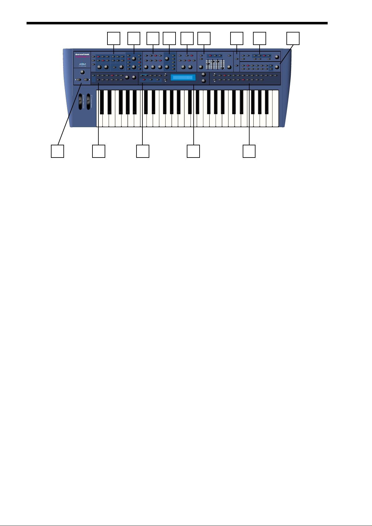
FRONT PANEL
1 - Master Volume Section
This section contains the Master Volume knob & the Octave up & down buttons.
2 - Oscillator Section
This section contains all the Knobs & buttons associated with the Oscillators.
3 - Arpeggiator Section
This section contains all the Knobs & buttons associated with the Arpeggiator.
4 - Oscillator Modulation Matrix Section
This section contains all the Knobs & buttons associated with the Oscillators Modulation Matrix.
5 - Filter Section
This section contains all the Knobs & buttons associated with the Filter.
6 - Mode Section
This section contains all the buttons used to select various modes.
7 - Filter Modulation Matrix Section
This section contains all the Knobs & buttons associated with the Filter Modulation Matrix.
8 - LFO Section
This section contains all the Knobs & buttons associated with the 2 LFOs.
9 - Display Section
This section contains the Display, the Data Knobs & Page buttons.
10 - Envelopes Section
This section contains all the knobs, sliders & buttons associated with the 3 Envelopes.
11 - Input Section
This section contains all the buttons associated with the 2 Inputs.
12 - Keypad Section
This section contains all the buttons used to select sounds.
13 - Effects Section
This section contains all the knobs & buttons associated with the Effects section.
14 - Part Edit Section
This section contains all the knobs & buttons associated with Parts of a Performance.
2
1 3 6 9 12
2 4 5 7 8 10 11 13 14
polyphonic synthesiser keyboard
master volume
octave
pitch mod
Oscillators
sources
osc 1 osc 2 osc 3 noise1*3 2*3
menu
square saw special
copy
Arpeggiator
trans
zone
fm fm fm
voice controltune
menu
up down u/d 1 u/d 2mutemenu
1 octon latch 2 oct 3 oct 4 oct
modulation
Filters
destination source
speed
menu 12db
lfo 1
mix
pitch
lfo 2
levelsolo
special
width
env 2
sync
env 3
modhardness wheelportamentocentsoct/semi part levelvel/out externalmidi polyphony rangetunedecay delay
demo tracks
gate time
program
compare writefind global
performance
modulation
18db 24db
low
band
assign
favourites
favourites
LFOs
lfo 1
lfo 2
square saw tri s/h
freq
high
env 2
env 3
global
page
Envelopes
menu
lfo 1 lfo 2menu
multi trigger
(env 2/3) attack sustain release prog leveldelay speedoverdriveresonancefrequency reso/width wheel mute
data
Inputs
Effects
overload
env 3
env 1
(amp) env 2
(poly limit)
copy distort/eq
menu
Part Edit
constant
23456
1 solo
gate
bank
config
reverb chorus
delaymenu bypass
level/balance
pan
vocoder
90 100 110 12001020304050607080
9012345678
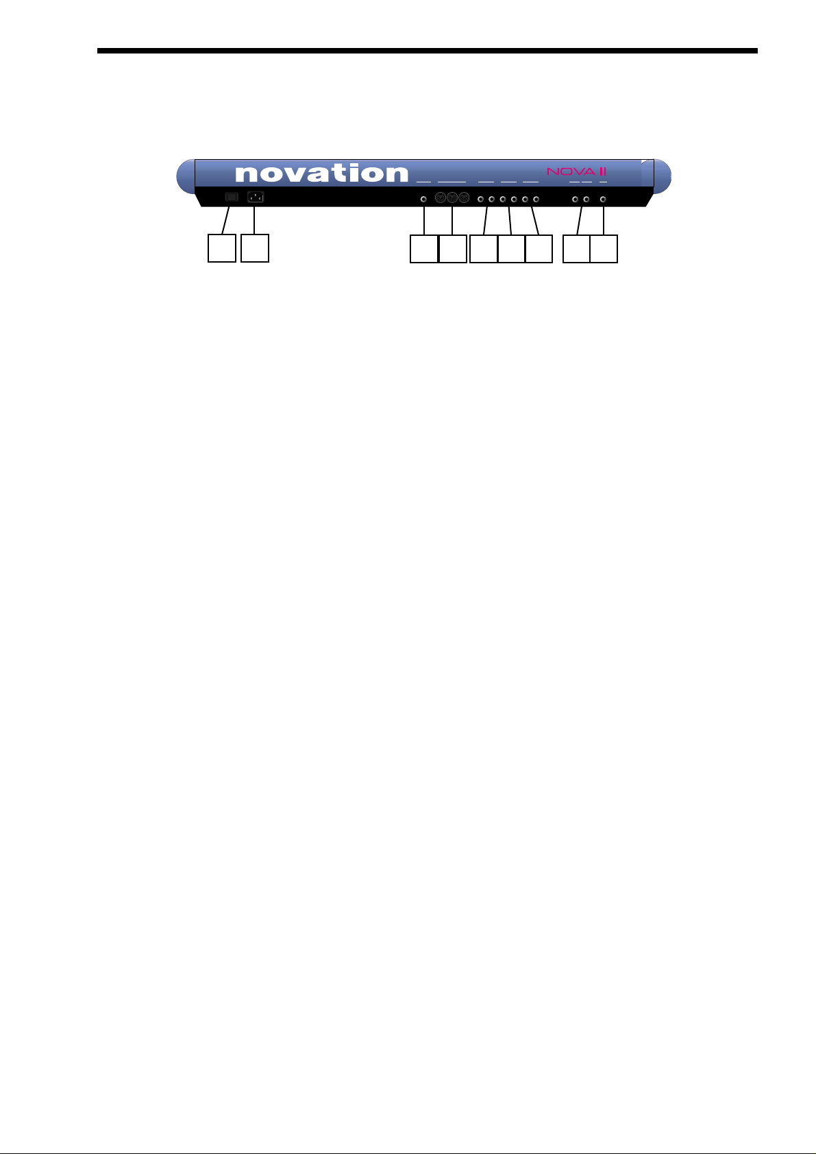
1 - Power On/Off - Switch.
This switch turns the mains power supply in the Nova II keyboard on & off. Edited & newly created Programs & Performances that
have not been saved will be lost if the Nova II keyboard is switched off. Be sure to save edited Programs & Performances to memory before switching Nova II keyboard off. Refer to page 38 & 41 for details of writing Programs & Performances into memory.
2 - IEC Mains Connector.
This socket is for the supplied Mains lead. This socket accepts 110V, 220V & 240V mains supplies at 50 or 60 Hz. In other words
the Nova II keyboard will work on any county’s mains supply.
3 - SPDIF Phono In & Out Connectors.
These phono sockets provide SPDIF format digital inputs & outputs supplied when the optional SPDIF/ADATcard is installed.
4 - ADAT Optical In & Out Connectors.
These optical connectors provide ADAT format digital inputs & outputs supplied when the optional SPDIF/ADAT card is installed.
5 - Pedal / Switch 3 Socket.
This 1/4 inch jack socket allows the connection of either a optional footswitch or expression pedal to be connected. The function is
user defined in the Global mode.
6 - MIDI IN / MIDI OUT / MIDI THRU Connectors.
The MIDI IN connector is used to receive MIDI Data from an external device.
The MIDI OUT connector is used to transmit MIDI Data to an external device.
The MIDI THRU connector re-transmits MIDI Data received by the MIDI IN socket to an external device.
7 - Master Left & Right / Aux 1 / Aux 2 & Aux 3 Audio Outputs.
The Master Left & Right 1/4 inch Jack sockets deliver a Stereo Line Level output signal for connection to a mixing desk or amplifier. The level of these outputs is controlled by the Master Volume Knob on the front panel.
The Aux 1 1/4 inch Jack sockets deliver a Stereo Line Level output signal for connection to a mixing desk or amplifier. These outputs can be used in addition with the Master Audio Outputs for more flexibility in live & studio applications.
The Aux 2 1/4 inch Jack sockets deliver a Stereo Line Level output signal for connection to a mixing desk or amplifier. These outputs can be used in addition with the Master Audio & the Aux. 1 Outputs for even more flexibility in live & studio applications.
The Aux 3 1/4 inch Jack sockets deliver a Stereo Line Level output signal for connection to a mixing desk or amplifier. These outputs can be used in addition with the Master Audio & the Aux. 1 & 2 Outputs for even more flexibility in live & studio applications.
8 - Input/SW2 & input/SW1 Connectors.
These 1/4 inch Jack sockets provide 2 audio inputs for synthesis, filtering or effect processing or as footswitch inputs. The function
of these sockets is user defined in the Global mode. When used as audio inputs the sensitivity is user defined in the inputs menu.
9 - Headphones - Socket.
Use this 1/4 inch Jack Socket to monitor the Left & Right output of the Nova II keyboard via headphones. This output will drive any
type of headphones. The Nova II keyboard’s headphone amplifier will deliver a louder signal if low impedance headphones are
used. i.e. 8 ohms impedance. Be aware that the sound pressure level obtainable with low impedance headphones could damage
hearing.
BACK PANEL
3
1 2
3 4 5 6 7 8 9
O I
pedal/switch3 aux 1aux 2midi
master
4365thru out in
21
phones
input/sw1input/sw2
(sustain)
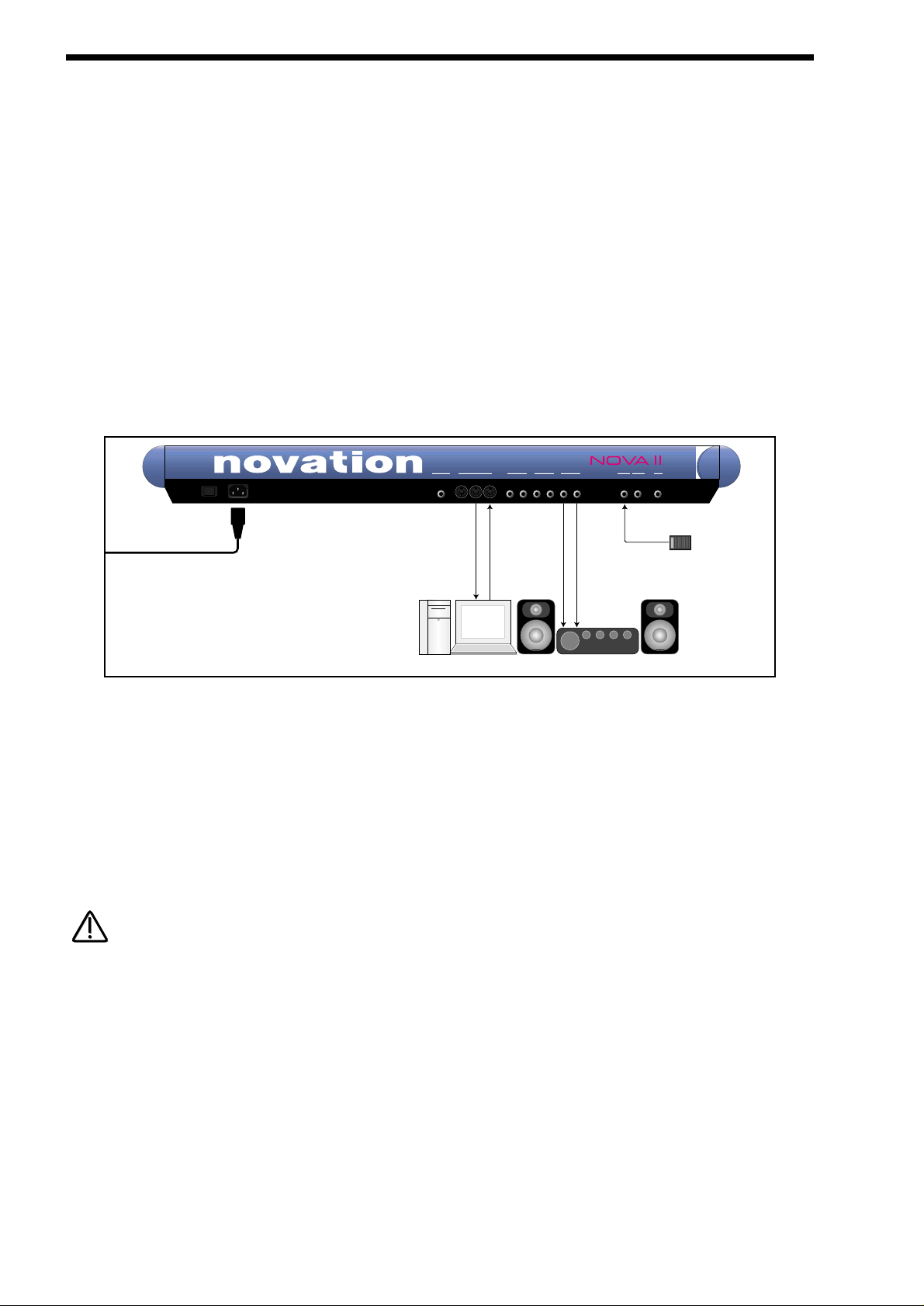
SETTING UP - BASIC SETUP
Setting up
Connect the Master left & Right Audio Outputs ( & the Aux. 1, Aux. 2 & Aux. 3 Audio Outputs if required ) of the Nova II keyboard to
a suitable amplifier or mixing desk’s stereo inputs & set the Master Volume control on the Nova II keyboard to a reasonably high
output level ( 9 - 10 ). This will maintain a good signal to noise ratio. Make sure the input volume on your amplifier or mixing desk
is initially set to zero.
Make sure that the Nova II keyboard’s mains switch is in the “OFF” position. Connect the Mains supply with the supplied lead to
the Mains Socket on the Nova II keyboard. Connect the other end to the mains supply & switch the supply on. The display should
now illuminate showing the Performance, Program or Favourite that was selected the last time global data was written into memory. Refer to page 48 for details on this function. Now switch on your amplifier & adjust the volume accordingly whilst playing the
keyboard.
The keyboard will be playing the currently selected Performance, Program or Favourite. To listen to all of the Factory sounds, make
sure you are in the Performance, Program or Favourite Mode by pressing the Performance, Program or Favourite Button & use the
Keypad section to call up the different sounds. For details on how to select the different Performances & Programs & what they are
refer to page 33.
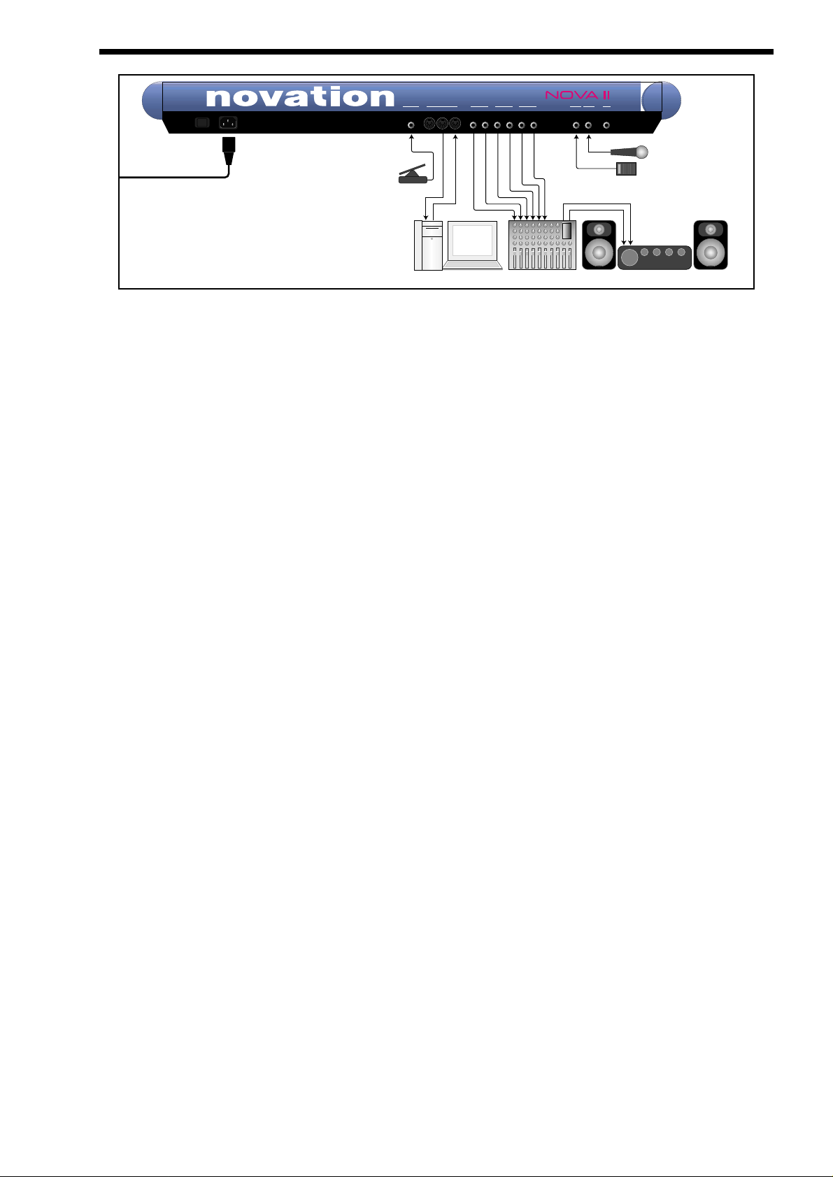
Basic setup
Above is a diagram of the basic way to set-up the Nova II keyboard. Normally the set-up would be as follows: Connect the Nova II
keyboard as shown above. Set the “Local On/Off” parameter on page 7 of the Global mode to OFF. Turn the Computer Software /
Sequencer’s “Soft Thru” ( or sometimes called “Echo Back” ) to the “ON” or “Enabled” position. Now when selecting a “Track” in the
computer Software / Sequencer that is assigned to the same channel as the Nova II keyboard is set to receive on ( If this is a
Performance you can set the receive channels individually for each “Part”. Refer to page 123 for details, If this is a Program,
Programs are played on the “Global MIDI Channel. Refer to page 48 for details.) playing the keyboard should should produce
sounds through the Headphones / Monitors.
The Nova II keyboard can have virtually any parameter controlled via MIDI. The movement of any knob, the pressing of any button
or change to any parameter can be recorded with this setup. These recordings can then be easily edited on a sequencer. Details
on all the controllers & NRPNs used by the Nova II keyboard can be found on page 138 to page 139.
If there are additional keyboards / Modules connected via MIDI, this diagram does not include audio for the keyboards / Modules.
The audio outputs of these devices must also be connected to the mixer.
To listen to the Factory Demo
Once the Nova II keyboard is connected as shown you can listen to the Factory Demonstration. To do this press the Find & Global
buttons at the same time.
4
To Mains Supply
pedal/switch3 aux 1aux 2midi
O I
MIDI IN
Computer / Sequencer
MIDI OUT
master
4365thru out in
21
Amplifer / Mixer and Monitors
Audio Inputs
phones
input/sw1input/sw2
(sustain)
Sustain Pedal
NOTE:
NOTE:
This is the one of the more advanced ways to set up the Nova II keyboard. Connect the Nova II keyboard as shown above. Set the
“Local On/Off” parameter on page 7 of the Global mode to OFF. Turn the Computer Software / Sequencer’s “Soft Thru” ( or sometimes called “Echo Back” ) to the “ON” or “Enabled” position. Now when selecting a “Track” in the computer Software / Sequencer
that is assigned to the same channel as the Nova II keyboard is set to receive on ( If this is a Performance you can set the receive
channels individually for each “Part”. Refer to page 123 for details, If this is a Program, Programs are played on the “Global MIDI
Channel. Refer to page 48 for details.) playing the keyboard should should produce sounds through the Headphones / Monitors.
The Nova II keyboard can have virtually any parameter controlled via MIDI. The movement of any knob, the pressing of any button
or change to any parameter can be recorded with this setup. These recordings can then be easily edited on a sequencer. Details
on all the controllers & NRPNs used by the Nova II keyboard can be found on page 138 to page 139.
There are 4 stereo pairs of Outputs connected to the mixer. This allows individual sounds to be processed externally by the mixer
& other outboard equipment. To direct “Parts” of a “Performance” to these separate outputs Refer to page 122 for details.
Additionally, the Nova II keyboard automatically redirects the effects outputs for the selected part to go to the same outputs as the
part, so even if separate outputs are assigned the associated effects follow automatically.
Additionally a microphone is connected to Input/SW1 & this allows external signals to be processed by the synthesis engine (
including filtering ) and/or effects processors & Vocoder of the Nova II keyboard. In fact virtually any type of signal can be used by
the Nova II keyboard, as the gain of the 2 inputs can be adjusted from Microphone level through to Studio levels. (+4dBm ) Refer
to page 95 for details on how to use the inputs. The inputs can also double as Footswitch inputs & a footswitch is connected to
Input/SW2. The function of this can be user determined in the Global mode. Refer to page 52 for details.
An expression pedal input is also provided allowing a optional pedal to be connected. This allows the volume of the keyboard to be
controlled from the expression pedal. This to can be a footswitch input. The function of this Pedal/Switch input can be user determined in the Global mode. Refer to page 53 for details.
pedal/switch3 aux 1aux 2midi
4365thru out in
master
21
phones
input/sw1input/sw2
(sustain)
O I
Sustain Pedal
Microphone
Amplifer / Mixer and Monitors
Audio Inputs
Mixing Console
MIDI IN
Pedal
MIDI OUT
Computer / Sequencer
To Mains Supply
ADVANCED SETUP
5
ABOUT ANALOGUE SYNTHESIS
OSCILLATORS -
pitch
To understand synthesis, it is necessary to have some understanding about sound itself. Sound is a vibration or oscillation. These
vibrations create changes in air pressure which is picked up by your ears & is perceived as sound. When dealing with musical
sounds the vibrations or oscillations occur at regular intervals & are perceived as the “Pitch” or “Frequency” of a sound. The simplest musical sound is a sine wave because it contains only one “Pitch” & is perceived as a very “Pure” tone similar to a whistle.
Most musical sounds consist of several different “Pitches” or “Frequencies”. The loudest is referred to as the “Fundamental” &
determines the perceived “Pitch” of the note. The other frequencies present are called “Harmonics” & in musical sounds usually
occur in multiples of the fundamental frequency. i.e. if the fundamental note is 440Hz then a musical harmonic series would be 2nd
harmonic = 880Hz, 3rd harmonic = 1320Hz, 4th harmonic = 1760Hz, 5th harmonic = 2200hz etc. The number & loudness of these
“Harmonics” determines the “Timbre” of a sound. This gives a sound character & is why a violin sounds different from a guitar & a
piano sounds different again. In an Analogue synthesiser, you have the choice of several different waveforms. Each waveform has
different amounts of harmonics & so the “Timbre” of each one is quite different. Below are descriptions of some of the waveforms &
indications on what they can be best used for.
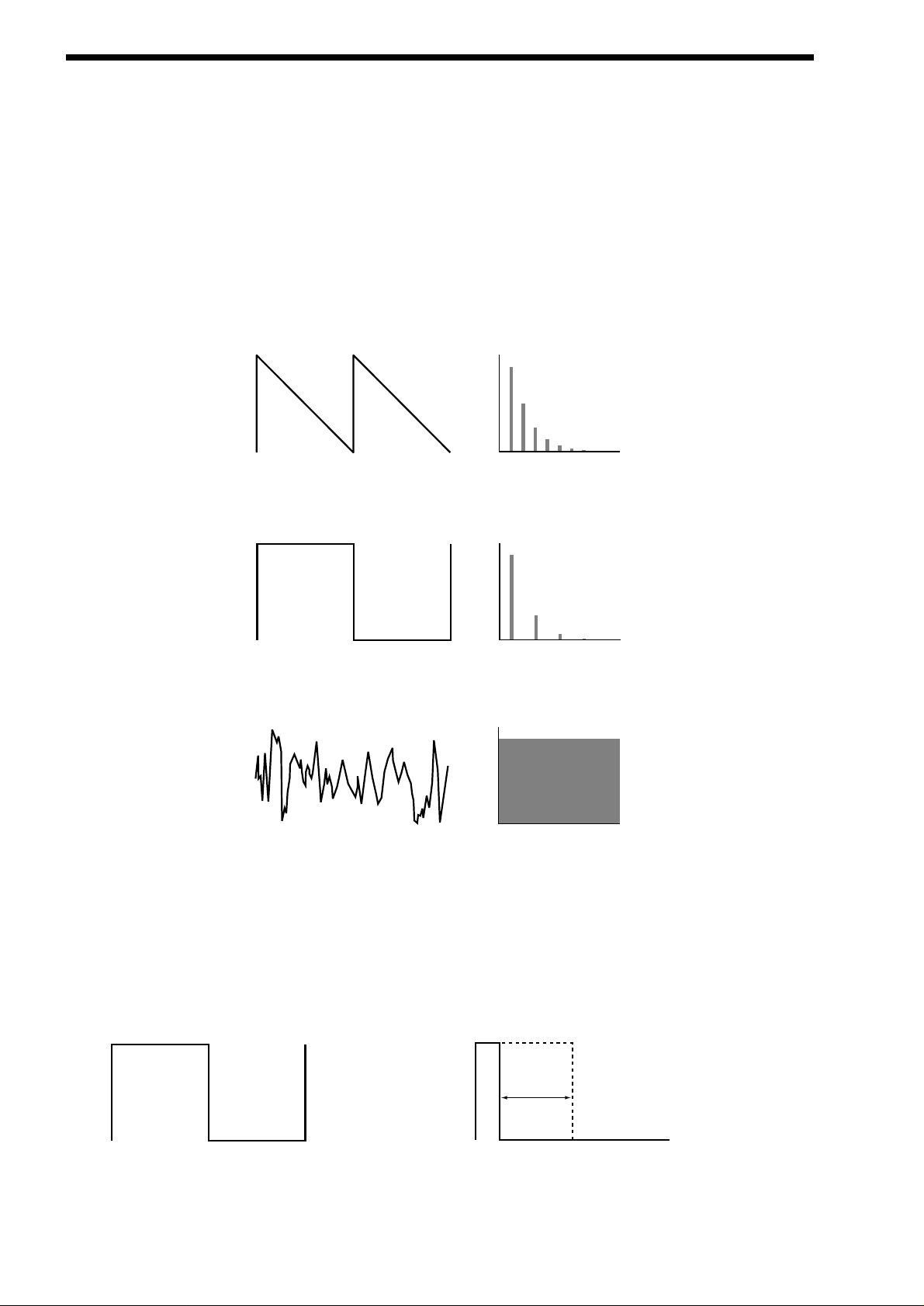
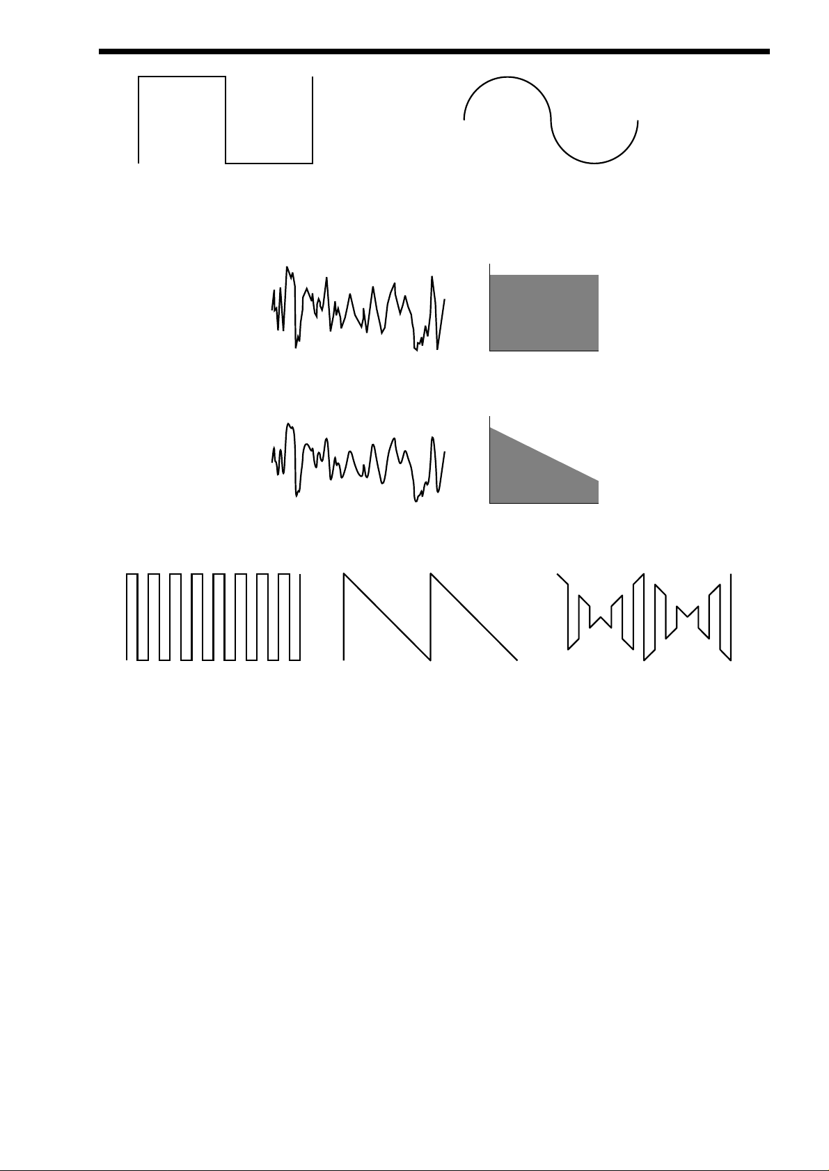
Sawtooth waves have all the harmonics of the fundamental frequency. As you can see, every harmonic has half the amplitude of
the previous one. This sound is pleasing to the ear & is useful for basses, leads, & synthesising stringed instruments.
Square waves have only the odd harmonics present. These are at the same amplitudes as the odd harmonics in a saw wave.
Square waves have a hollow / metallic sound to them & so are useful in creating unusual synthesiser sounds & oboe like sounds.
White noise has no fundamental & all harmonics are the same value. This wave can be used by itself to synthesise explosions or
wind & when used in conjunction with other waveforms can be used to create the illusion of “Breath” in an instrument.
PWM ( PULSE WIDTH MODULATION )
The choice of waveform is important as it determines the basic “Timbre” of the sound you are making. There are additional methods of synthesis that allow more harmonics to be generated. The First of these is Pulse Width Modulation. ( PWM for short ).
Essentially the duty cycle of the normally symmetrical square wave is varied. This means the wave form goes from a Square wave
to a Pulse wave like so:
This has a very pleasant “thickening” chorus like effect & is often used in Pad type & String section type sounds.
Additionally there is a synthesis method called Oscillator sync. This takes two oscillators & uses one ( the Master ) to reset the
6
Level
Saw Waveform
1234567
Harmonics
Level
Square Waveform
1234567
Harmonics
Level
Noise Waveform
1234567
Harmonics
Variable Width
Square Waveform
Pulse Waveform
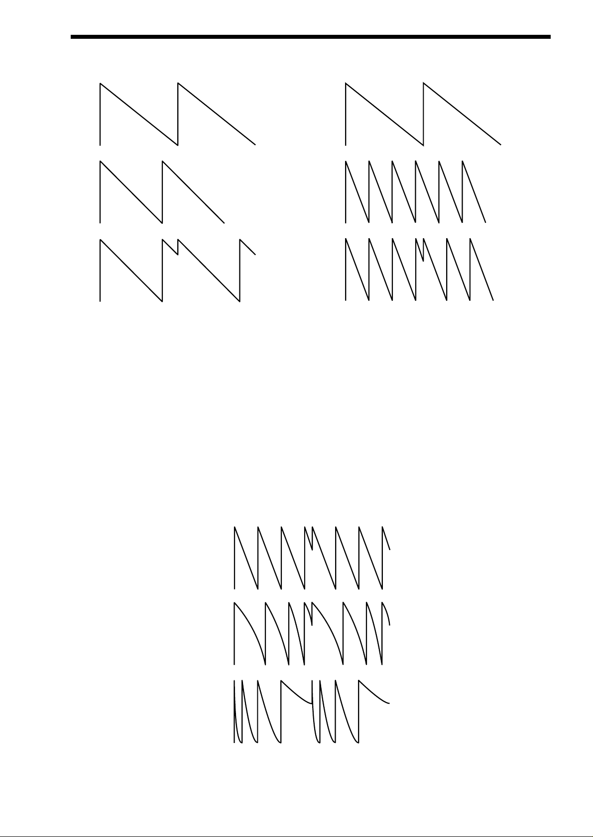
other ( The Slave ) each time it starts a new cycle. The effect is most noticeable when the two oscillators are out of tune as shown
below.
This Sync Effect creates very piercing & metallic sounds & are used a lot as lead sounds. It is worth noting that the Nova II keyboard does not require 2 oscillators to create this effect. The Sync “Effect” is created by the Analogue Sound Modelling process
without the need for a Sync Oscillator, there is merely a “Sync” parameter that creates the classic Sync Effect. This means that
each of the 3 oscillators in one Nova II keyboard “voice” can be independently Sync’ed as if there were 3 Master & 3 Slave oscillators.
Analogue Sound Modelling technology also enables the creation of some new “Sync” related parameters that are not found on
analogue synthesisers. These are “Key Sync”, “Sync Skew” & “Formant Width”
Normally on an analogue synthesiser, even though the Master & Slave oscillators are detuned relative to each other, they both
track keyboard pitch equally. i.e. if you play notes one octave apart, both the Master & the Slave oscillator will be transposed one
octave. “Key Sync” allows the slave oscillator to have its pitch tracking adjusted independently. This means that the “Sync Effect”
will change as you play different notes up & down the keyboard.
Sync Skew manipulates the frequency of the “virtual” slave oscillator within one cycle of the master oscillator. The result is that the Sync
Effect seems to have a higher frequency at the end of each cycle with positive modulation & at the start of the cycle with negative modulation. This parameter makes the sync waveform sound even harsher. This is particularly good for aggressive lead sounds.
ABOUT ANALOGUE SYNTHESIS
7
Osc1( Master )
Osc2 ( Slave )
Sync Waveform
Osc1( Master )
Osc2 ( Slave )
Sync Waveform
Normal Saw Sync Waveform
Positive Skew on a Saw Sync Wave
Negative Skew on a Saw Sync Wave
ABOUT ANALOGUE SYNTHESIS
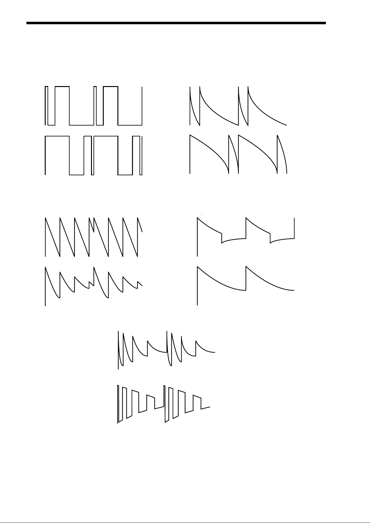
Sync Skew also effects the standard Square & Saw waveforms. The effect is to “swash” the waveform at the end of its cycle with
positive modulation & swashing the waveform at the beginning of the cycle. On a square wave, moderate amounts of this effect
produce similar effects to Pulse width modulation except width modulation over 100% can be achieved allowing may cycles to be
“swashed” into one original one. This can also be described as Frequency Modulation within the cycle & so mimics classic “Cross
Modulation” with a Saw wave. This can produce effects similar to Sync but when this parameter is used in conjunction with
Formant Width the results can be very different. Below are examples of Sync Skew on standard Square & Saw waveforms. Note
how the wave is swashed at one end & more than one cycle has been swashed into the original cycle.
Formant width is a parameter that controls the level of the cycles of the “virtual” slave oscillator. This can be used to simulate resonance within the oscillator itself by using the “Harden” parameter to smooth out the sharp edges of this wave form. The effect is to
reduce the level of every successive slave cycle. Additionally this parameter has an effect on the normal Saw & Square waveforms.
The effect is to boost the treble content of these waves.
Both Sync Skew & Formant Width can be used in conjunction to create yet even more waveforms. Below are examples.
Analogue Sound Modelling technology allows even more control over the waveform. Once you have selected you basic oscillator
waveforms you can further modify then using a “Hardening” process. This “Hardening” rounds off all the “Sharp” edges of the
waveform, thereby reducing its harmonic content. Below is an example of the “Harden” parameter on a Square wave.
y
8
Negative Skew on a Square Wave
Positive Skew on a Square Wave
Negative Skew on a Saw Wave
Postive Skew on a Saw Wave
Sync Waveform
Sync Formant Width Waveform
Formant Width on a Square Wave
Formant Width on a Saw Wave
Negative Skew & Formant Width on a Saw Wave
Negative Skew & Formant Width on a Saw Wave
The Harden parameter is completely variable & can reduce a square wave to only one harmonic producing a Sine wave. The
Harden process can also be applied to the noise generator providing control over the harmonic content of the noise. Below is an
example of the “Harden” parameter on Pink Noise.
Finally there is Ring modulation. This uses two oscillators but instead of adding them together like in a mixer they are multiplied
together. This is very similar to FM & produces the kind of effect shown below:
The Ring Modulation effect creates metallic & bell like sounds & is used generally for lead sounds, but if used subtly can produce
Electric Pianos etc & if used radically can produce unusual sound effects.
All these methods further enhance the basic Oscillator waveforms to include many more or a useful mix of harmonics. Once the
waveforms have been selected you can then “fine tune” the harmonic content of the mixture of different waveforms by passing
them through a “Filter” to remove unwanted harmonics. The filter in an Analogue synthesiser is a very powerful “Tone Control”. Like
the tone control on a stereo, the filter can alter how things sound but it cannot change the style of music being played on the
record, & so the filter in a synthesiser can alter the “tone” of a sound but is restricted by the basic “Timbre” of the waveforms. For
this reason, several waveforms are available at once & you can “Mix” them together to provide more harmonically rich waveforms.
Below is a diagram showing the signal path in the Nova II keyboard & all the waveforms at various locations.
ABOUT ANALOGUE SYNTHESIS
9
Square Waveform
Softened Square Waveform
Level
Noise Waveform
Softened Noise Waveform
1234567
Harmonics
Level
1234567
Harmonics
Osc1
X
Osc2
=
Ring Modulated Waveform
Osc1 x Osc2
ABOUT ANALOGUE SYNTHESIS
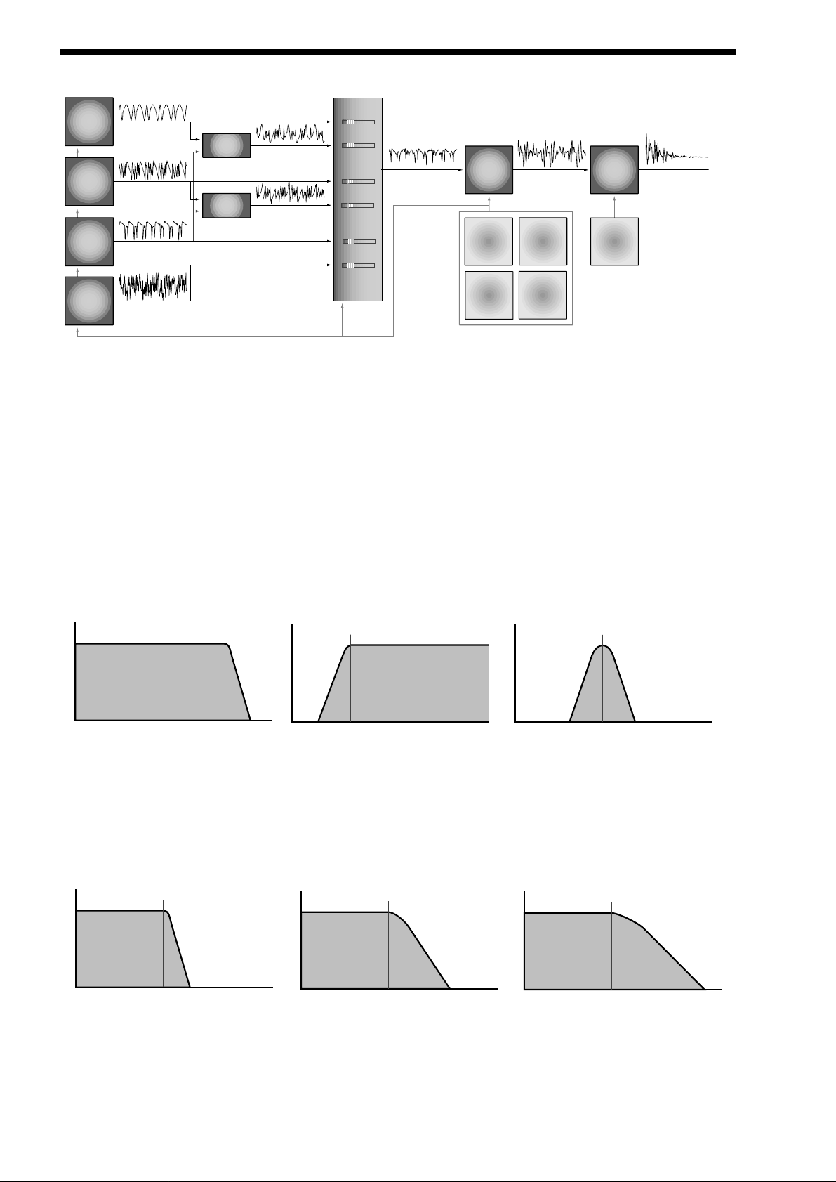
Different waveforms are being produced by different oscillators using different techniques. The Oscillators, Ring Modulators & the
Noise Generator all being Mixed together & feed to the filter. The signal is then in turn fed to the Amplifier. Oscillator 1 is using a
Square wave modulated by Sync Skew & then Hardened to create a sine-like wave except it has an extra bump in it. This produces a Whistle like sound. Oscillator 2 is using a Saw wave modulated by Sync Skew & Sync producing a Harsh sound &
Oscillator 3 is using a Square wave modulated by Sync Skew & Formant Width to produce a bright PWM like waveform. The 1*3
Ring modulator & the 2*3 Ring modulator are producing complex waveforms & these along with all the Oscillators & the Noise generator are fed to the Mixer.
FILTER -
tone
There are several different types of filter. These are Low Pass Filter, High Pass Filter & Band Pass Filter.
The Low Pass Filter allows harmonics below a set frequency to pass through the filter. Hence the name Low Pass Filter.
The High Pass Filter allows harmonics above a set frequency to pass through the filter. Hence the name High Pass Filter. The
Band Pass Filter allows harmonics at a set frequency to pass through the filter, the harmonics above & below the set frequency do
not pass through the filter. Hence the name Band Pass Filter. Below are the frequency response curves of the three types of filters.
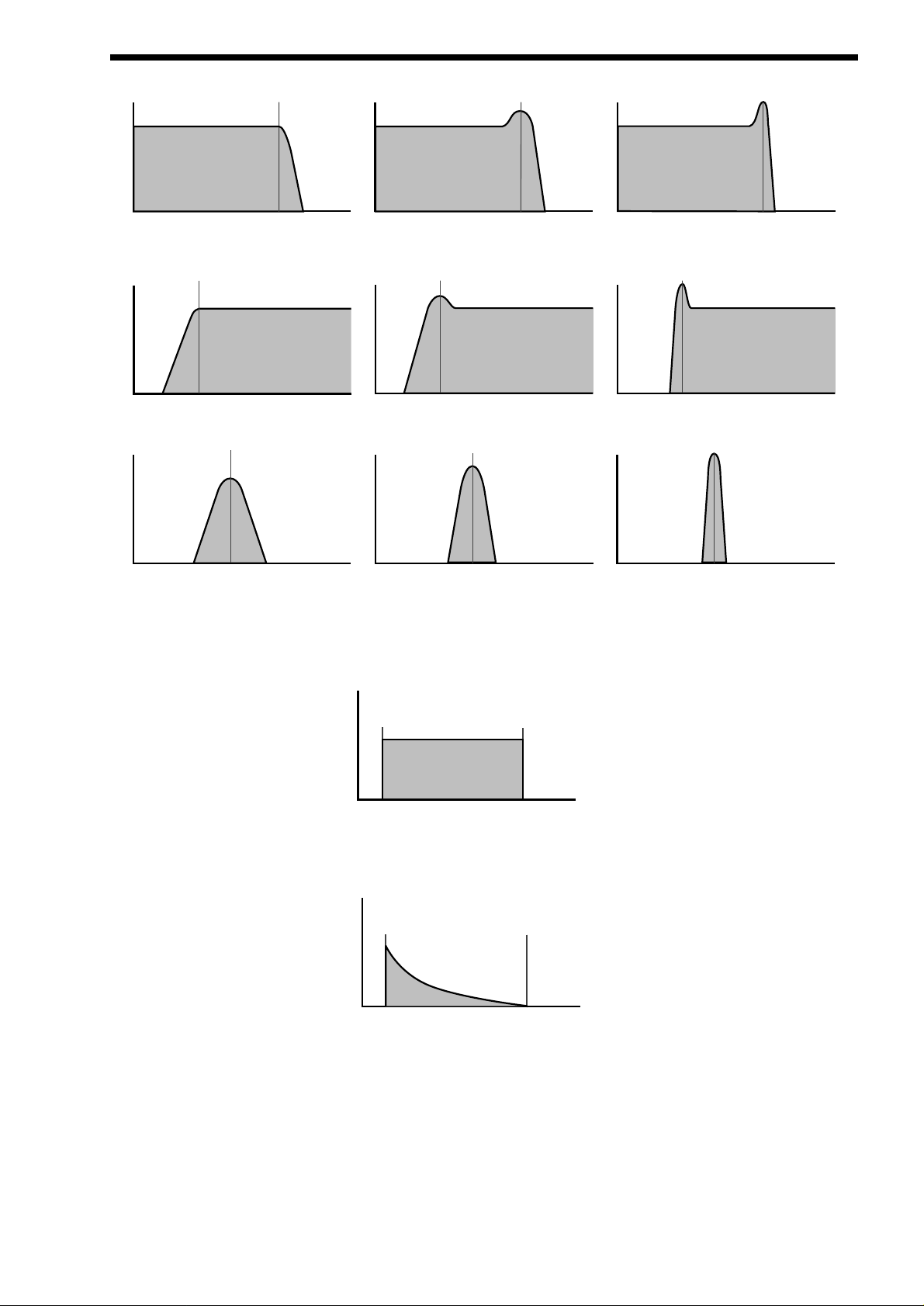
Additionally the slope of the curve at which the filter rejects unwanted harmonics can be altered. The effect is similar to a “Q” control on a parametric EQ. In the 12db position the Cutoff Frequency slope is less steep so the higher frequencies are not attenuated
as much as they are in the 24 or 18db positions. This makes the resulting filtering in the 12db position more subtle than the 24 or
18db positions which you should select if you want the Cutoff Frequency to be more obvious. The slope is measured in db per
Octave & below are the response curves of a Low Pass Filter with 24, 18 & 12 db per Octave slopes.
All these filters have a Resonance parameter. This has the effect of emphasising harmonics at the cutoff frequency of the filter.
This is very useful for creating large tonal differences to a basic waveform. The effect is shown below as both frequency response
curves when resonance is applied in a the Filter.
10
Signal Path Diagram
Osc 1
Osc 2
Osc 3
Noise
Gen
Osc 1 output
( Sq wave Softened with
+ve Skew )
Osc 2 output
( Saw wave Synced with
+ve Skew )
Osc 3 output
( Sq wave Synced with
+ve Skew & Formant width )
Pink noise output
Osc 1*3
Ring Mod
Osc 2*3
Ring Mod
Ring Mod output
Ring Mod output
MIXER
Osc 1 level
Osc 1*3 level
Osc 2 level
Osc 2*3 level
Osc 3 level
Noise level
Mixer output Filter output Amp output
Filter Amp
Env 2
LFO 1
Env 3
LFO 2
Env 1
Cutoff
Volume
Frequency
Frequency
Low Pass Filter Responce Curve
Volume
High Pass Filter Responce Curve
Cutoff
Frequency
Frequency
Cutoff
Volume
Frequency
Frequency
Band Pass Filter Responce Curve
Volume
Cutoff
Frequency
Volume
Cutoff
Frequency
Volume
Cutoff
Frequency
Frequency
24db/oct LPF Responce Curve
18db/oct LPF Responce Curve
Frequency
Frequency
12db/oct LPF Responce Curve
AMPLIFIER -
volume
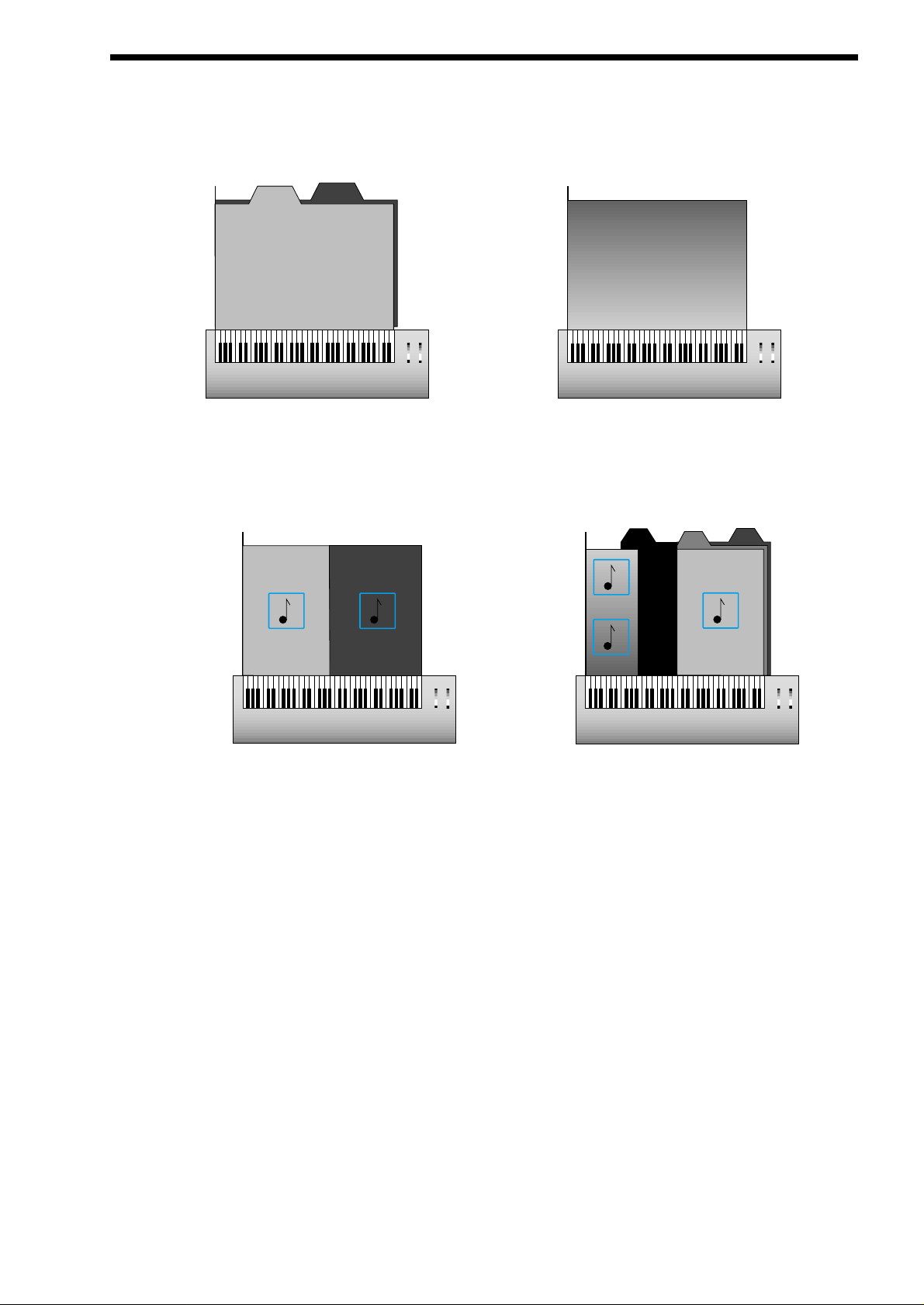
The last major process that makes up a sound is its “Volume”. The “Volume” of sounds vary as time goes by & so an Organ has
very different volume characteristics than that of a Piano or String section. See the following diagrams for details.
The “Organ” can be seen to go to full volume instantly when a key is pressed & then stay there until the key is released at which
point the volume drops instantly to zero.
The “Piano” can be seen to go to full volume instantly when a key is pressed & then gradually fall back down to zero over several
seconds.
ABOUT ANALOGUE SYNTHESIS
11
Cutoff
Frequency
Volume
No Resonance Mid Resonance High Resonance
Volume
Frequency
Cutoff
Frequency
Frequency
Volume
Low Pass Filter with Resonance Responce Curves
Cutoff
Frequency
Volume
No Resonance Mid Resonance High Resonance
Volume
Frequency
High Pass Filter with Resonance Responce Curves
Volume
Cutoff
Frequency
Volume
No Resonance
Cutoff
Frequency
Frequency
Cutoff
Frequency
Volume
Volume
Mid Resonance
Cutoff
Frequency
Frequency
Frequency
Cutoff
Frequency
Cutoff
Frequency
Frequency
Frequency
Frequency
Band Pass Filter with Resonance Responce Curves
Volume
Key "On"
Key "Off"
Time
"Organ" Type Volume Response Curve
Volume
Key "On"
Time
"Piano" Type Volume Response Curve
Key "Off"
ABOUT ANALOGUE SYNTHESIS
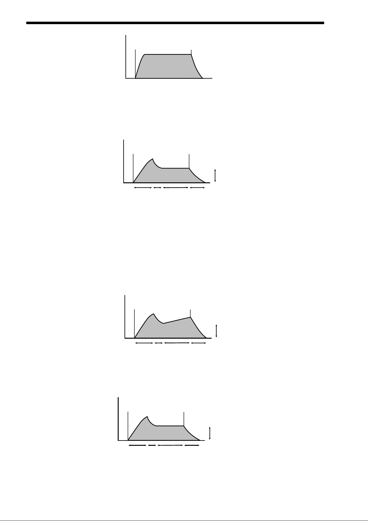
The “String section” can be seen to go to full volume gradually over several seconds when a key is pressed & then stay there until
the key is released when gradually over a couple of seconds the volume drops to zero.
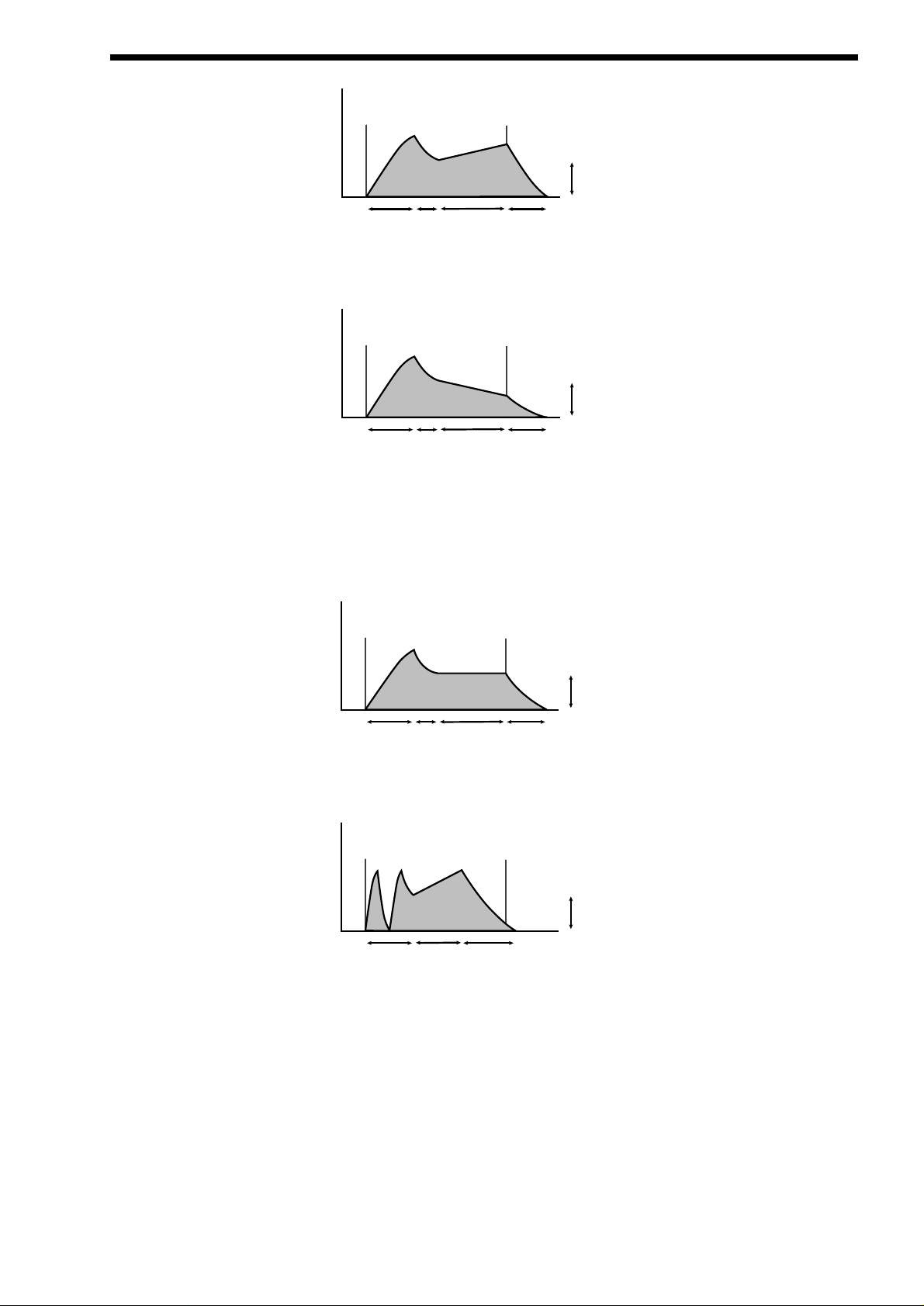
These curves are called “Envelopes” & in an Analogue synthesiser “Envelope Generators” are used to recreate them. Envelope
Generators have 4 parameters which are used to adjust the shape of the envelope, see the diagram below:
Attack time is used to adjust the time it takes when the key is pressed for the envelope to go from zero to full value. ( Fade in )
Decay time is used to adjust the time it takes for the envelope to go from full value to the value set by the Sustain level. ( Piano
like decay of volume )
Sustain level is used to set the level that the envelope remains at while the key is held down.
Release time is used to adjust the time it takes when the key is released for the level to go from the sustain value to zero. ( Fade out )
The Nova II keyboard also offers additional envelope features to the classic ADSR types allowing even more flexibility, see the diagram below:
In addition to the Attack, Decay, Sustain & Release parameters there is also 3 new parameters. These are:
Sustain Rate which is used to control the slope of the “Sustain” phase of the envelope. When this parameter is set to 0 the curve
is normal like so:
When this parameter has a +ve value, during the “Sustain” phase of the envelope the Sustain value will rise to full at a “Rate”
determined by this parameter as can be seen below:
12
Volume
Key "On"
Key "Off"
Time
"String Section" Type Volume Response Curve
Volume
Key "On"
Decay
Time
Infinite Sustain
Time with
no Sustain Rate
Attack
Time
ADSR Type Volume Response Curve
Key "Off"
Sustain level
Release Time
Volume
Key "On"
Attack
Time
Decay
Time
Infinite Sustain
Time with
+ve Sustain Rate
Key "Off"
Sustain level
Release Time
ADSR Type Volume Response Curve
Volume
Key "On"
Key "Off"
Sustain level
Decay
Time
Infinite Sustain
Time with
no Sustain Rate
Release Time
Attack
Time
Low values like +01 will produce a very slow rise & high values will produce a quick rise to full intensity. When this parameter has a
-ve value, during the “Sustain” phase of the envelope the Sustain value will fall to zero at a “Rate” determined by this parameter as
can be seen below:
Low values like -01 will produce a very slow fall & high values will produce a quick fall to zero intensity.
A-D Repeat allows the Attack & Decay phases of the envelope to be looped, producing repeated cycles of Attack & Decay curves.
This is fully adjustable from Off ( normal ADSR operation ) to 126 repeats & Infinity.
Sustain Time which is used to control how long the “Sustain” phase of the envelope will last. When this parameter is set to 127 (
infinite ) the curve is normal like so:
When this parameter is set to anything less than 127 the “Sustain” phase has a defined time duration & can be adjusted from very
long to very short, so that the “Sustain” phase may end before the key played is released at which point the “Release” phase will
start automatically. Below is an example of all 3 new parameters working together:
Summary
An Analogue Synthesiser can be broken down into three main elements.
1 - The Oscillator is the part of a synthesiser that generates “Waveforms” at a certain “Pitch”.
2 - The type of “Waveform” selected in the Oscillator & the settings of the “Filter” determine the “Tone” of the sound.
3 - The sound is then passed through an “Amplifier” which is controlled by an “Envelope Generator”. These alter the
“Volume” of a sound over time.
ABOUT ANALOGUE SYNTHESIS
13
Volume
Key "On"
Attack
Time
Decay
Time
Infinite Sustain
Time with
+ve Sustain Rate
Key "Off"
Sustain level
Release Time
Volume
Key "On"
Attack
Time
Decay
Time
Infinite Sustain
Time with
-ve Sustain Rate
Key "Off"
Sustain level
Release Time
Volume
Key "On"
Attack
Time
Decay
Time
Infinite Sustain
Time with
no Sustain Rate
Key "Off"
Sustain level
Release Time
Volume
Key "On"
A/D Repeat
set to 1
Short Sustain
Time with
+ve Sustain Rate
Key "Off"
Sustain level
Release Time
ABOUT ANALOGUE SYNTHESIS
All of these three main elements can be controlled by various methods for example:
The “Pitch” of a note can be played on a keyboard or a synthesiser & additionally it can be manipulated in real time using the
“Pitch Bend Wheel” to create “Slides” & “Bends” in pitch. LFOs ( low frequency oscillators ) can be used to “Wobble” the pitch of a
note at a specific rate creating a “Vibrato” effect. An Envelope Generator can also be used to “Slide” the pitch in an automatic way.
The Filter can be manipulated by LFOs to vary the “Tone” of a sound at a specific rate creating a “Wah Wah” type of effect. An
Envelope Generator can also be used on the Filter so that the “Tone” of a sound changes over time. Afeature called “Keyboard
Tracking” can also be used on the Filter so that the “Tone” of a sound changes depending on the note being played.
The Amplifier can be manipulated by Envelope Generators so that changes in the “Volume” of a sound over time can make the
sound short & percussive, or more like a piano or even like an organ. Additionally the “Velocity” at which you hit the keys can also
be used to manipulate volume making a sound more “expressive”.
The elements that manipulate these three main synthesis elements are called “Modulation Sources”.
The Nova II keyboard features 3 Envelope generators & 2 LFOs ( Low Frequency Oscillators ) as Modulation “Sources”. In addition
to this Velocity, ( The dynamics of your keyboard playing. i.e. ppp to fff ) Aftertouch (Pressure on the keyboard while note(s) are
held ) & the Modulation Wheel are included in a as additional “Sources” of modulation signals in a “Modulation Matrix”. This allows
almost any “Source” to modulate a given parameter. It is even possible to have combinations of different “Sources” modulating one
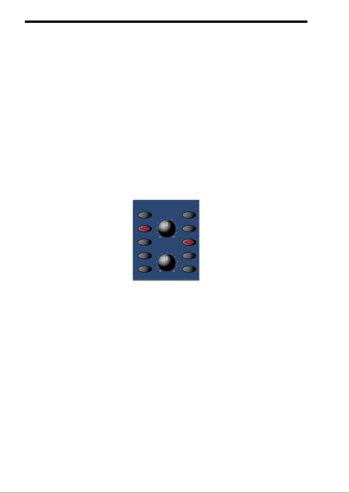
parameter. In the Nova II keyboard this has been neatly arranged on the front panel so that accessing all the possible combinations of modulation is quick & easy. Below is the Modulation Matrix for the Oscillator section.
Oscillator Modulation Matrix
Simply by pressing the desired “Source” ( the row of buttons on the right ) & the desired “Destination” ( the row of buttons on the
left ) & adjusting the “Level” or “Mod Depth” knobs allows the creation of complex modulation setups easily. On older modular
Analogue Synthesisers this was done with “Patch” leads that physically connected the “Sources” & “Destinations” together.
This allows some very powerful performance features to be implemented. i.e. It is possible to sweep the “Sync” effect, “Harden”
effect, Pulse Width Modulation & alter the Mix of all three oscillators independently plus open the Filter Cutoff Frequency, Reduce
the Filter Resonance, add lots more Distortion & Delay & reduce the Chorus & Reverb, all by simply moving the Mod Wheel forward! With the Modulation Matrix relationships like this are quick to set up & will transform a “static” sound into one with real
“hands on” control & flexibility.
This is where most synthesisers end. However, the Nova II keyboard features a very powerful Effects section. It could be said that
effects are as much “part” of a sound as the raw sound itself. Some of the larger old Analogue systems had built in spring reverb, &
with the development of DSP technology, digital effects have become available in modern synthesisers. However when in a
“Multimbral” application, all the sounds are generally passed through one set of effects.
In the Nova II keyboard, a block of 7 effects is part of the “Program” & can be considered to be part of the synthesis engine. These
include Distortion, EQ, Reverb, Rotary Speaker/Ensemble/Chorus/Flanger/Phaser, Delay, Panning & Comb Filter effects. These
can simulate “Real World” effects like Echo & Room Reverberation etc. Or they can be used to just do really weird things to your
sound! For details on what each effect does & how best to use them refer to the about Effects section part of this manual on page
18 for details.
The best thing to do is just get in there & tweak those knobs, after all that’s why we put them there! Experiment & you’ll soon be
creating your own sounds. Don’t worry about erasing the factory sounds in the memory. If you want, the factory sounds can be
recalled. To do this Refer to page 52 for details.
level
mix
pitch
width
sync
lfo 1
lfo 2
env 2
env 3
modhardness wheel
destination source
modulation
14
Basic Theory
Earlier in this manual we were introduced to the basics of subtractive synthesis & became familiar with terms such as harmonics,
timbre, waveforms & oscillators. FM Synthesis is the technique of using one waveform ( Oscillator ) to Frequency Modulate - FM another to produce a resultant more harmonically complex waveform.
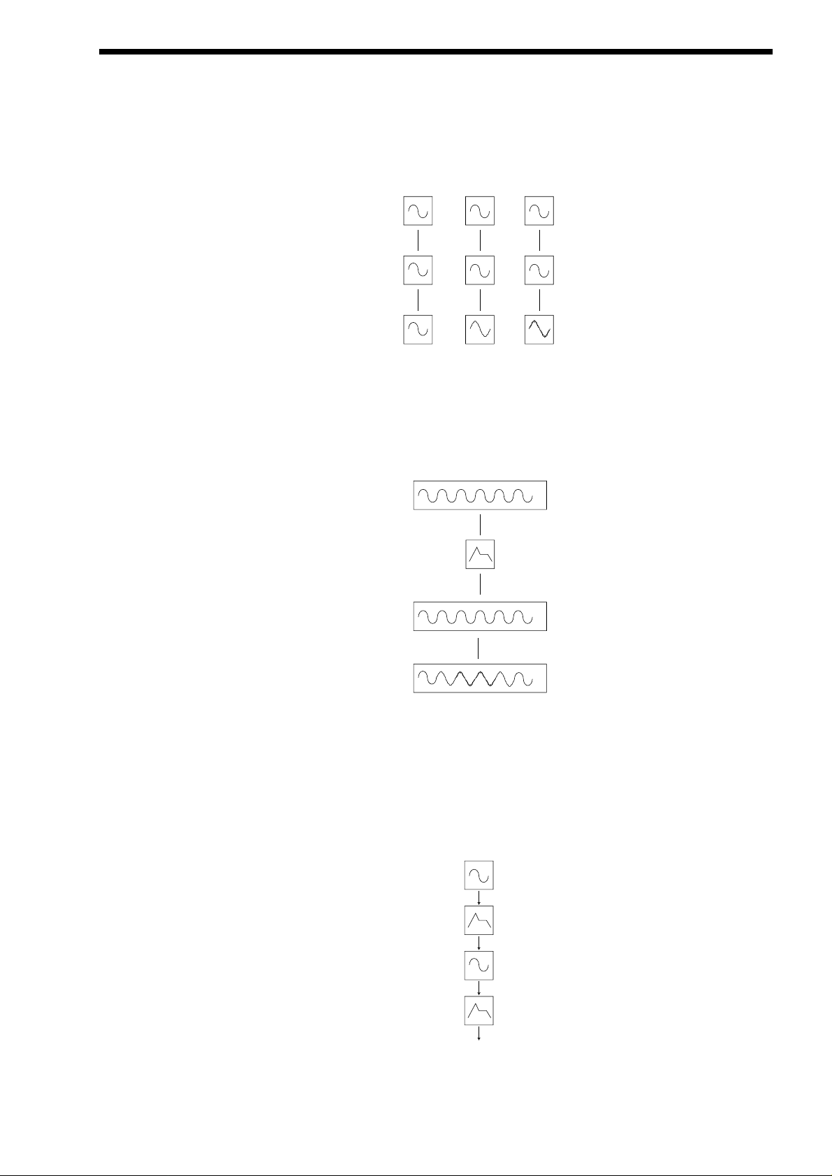
For purposes of illustration we will assume that the oscillators are producing sine waves.
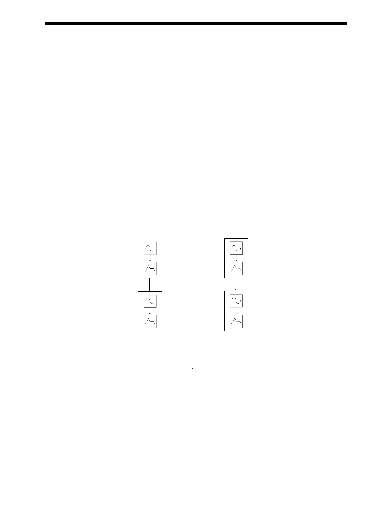
As we have already discovered it is the CHANGE in harmonics over time that starts to make a sound interesting to our ears. In FM
synthesis an envelope generator is inserted between the modulator & carrier waveforms so we have control over of how much
Frequency modulation is taking place with respect to time.
Adding this envelope makes the basic FM building block look like this
We can see that the output waveform starts off as the same as the carrier, becomes more complex (HARMONICS ARE ADDED)
as the amount of FM modulation increases via the envelope, & then returns to a simple wave again as the envelope decays. THE
TIMBRE OF THE WAVEFORM IS CHANGING WITH TIME. This is the opposite of subtractive synthesis where often a LOW PASS
FILTER is used to REMOVE HARMONICS.
To complete this simple synthesizer we need to add one further envelope to control the volume of what we are hearing. The complete building block will now look like this.
ABOUT FM SYNTHESIS
15
Osc 1- Modulator
Modulation level = 0 = 30
Osc 3- Carrier
Output Waveform
= 90
Osc 1- Modulator
Envelope
modulation
level = 20
Osc 3- Carrier
Output Waveform
Modulator
Env - used to
control FM
modulation
amount
Carrier
Env - used to
control amplitude
of sound over
time
Output
ABOUT FM SYNTHESIS
Yamaha popularised FM synthesis in the 1980’s with the famous DX7 synthesiser.The basic building block of the original Yamaha
machine was referred to as an OPERATOR. An operator is just one oscillator with one envelope generator that can control the output level of the Oscillator.
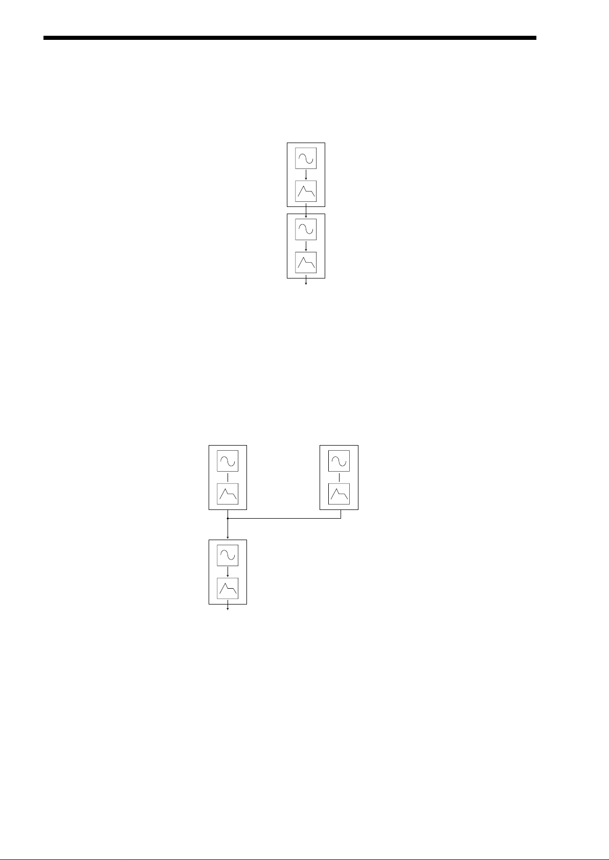
Referring to our simple synthesiser in the diagram above we can outline the different sections & see that it comprises of two
blocks, each one containing one oscillator & one envelope. This is known as a 2 OPERATOR SYSTEM in DX7 Language
The DX7 had six operators & they were presented to the user in preset combinations referred to as ALGORITHMS. This terminology of OPERATORS & ALGORITHMS immediately presented users of this new digital technology with a mystifying machine interface, thus creating original sounds was very often left to professional programmers. We will to make things clearer with the
SUPERNOVAII so you may gain the knowledge to create your own FM sounds.
Programming of your own FM sounds using the Nova II keyboard.
In any one PROGRAM of the Nova II keyboard we can make up to 3 OPERATORS using the oscillators & envelopes available. We
can also add a noise waveform for special effects & Drum/Percussion sounds. For simplicity most of the factory presets use the
same structure as in the diagram below.
ANoise waveform maybe substituted for Osc1 or Osc2
Many musical instruments contain much of the detailed sonic information during the first few moments that the instrument is
plucked, struck or blown. For example when a Xylophone is struck, during the small amount of time after the beater has made contact with the wood it will resonate & contain many harmonics. The sound will then settle down to a more periodic waveform.
The easiest way to learn & understand FM is to study a few of the factory presets. So lets start with the Xylophone
Select the FM sound Program D115"FMpt Xylo Lo".
When manipulating FM sounds most of the "tweaking" will be done in the using the envelope section & oscillator section.
Because we are now using an additive form of synthesis it is not really necessary to use the filter section. However it may be used
to enhance the sound further if required.
16
Operator 1
Operator 2
Output
Osc1
Env3
Osc3
Env1
Amplifier
Operator 1
Operator 3
Output
Osc2
Env2
Operator 2
When using the Nova II keyboard for FM synthesis it is important to note that it is ALWAYS Oscillator 3 that is heard as an output
to the mixer section. If you are creating sounds from scratch we recommend using the program D126 “FM Init Program” as a starting point as all the oscillators are set to sine waves & only oscillator 3 has its mix level turned up.
Referring to the graphic above we have Oscillator 3 doing the "Body" of the sound. We then have Oscillator 1 via env3 Modulating
Oscillator 1 for a small amount of time to simulate the effect of the beater. To hear just the body of the sound, press "osc3" in the
Oscillator Section & press "solo". - Make sure that the button "fm" under the 1*3 is NOT LIT. Play the keyboard & listen to the
sound. You are hearing a softened square wave that is in fact a sine wave. Whilst playing the keyboard press the "hardness" button & slowly rotate the "Level" knob. Notice how the sound becomes harder. Turn the knob back to so that the soften level is zero.
Now press the "fm" button. You can hear the FM effect of Oscillator 1 coming in via envelope 3. The extra harmonics are now audible at the start of the sound & it resembles a real Xylophone.
The amount of time that this FM is taking place is controlled by env3. env3 is allowing an amount of Oscillator 1 to FM Oscillator 3.
Experiment by selecting env3 in the Envelopes section & varying the decay time. Also Experiment with changing the pitch of Osc1.
To do this press the "osc1" button & turn the "oct/semi" or "cents" knob.
Ageneral rule in FM synthesis is that the HIGHER THE FM MODULATION AMOUNT, THE HARDER OR BRIGHTER THE SOUND
BECOMES.
The real power of FM in the Nova II keyboard is the ability to "stack" programs into performances.
The Performance "FM Xylophone" in B025 is actually made from 2 programs. The program as described above (FMpt Xylo Lo) &
FMpt Xylo Hi. From the names you can work out which program is doing what part of the sound !!!!!
To hear the 2 programs together select Performance B025. This is a layer of the 2 programs.
In terms of Operators this sound will now look like this in block diagram form.
ABOUT FM SYNTHESIS
17
Osc1
Env3
Osc3
Env1
Amplifier
Operator 1
Operator 2
ProgA
Fmpt Xylo Lo
Output
Osc1
Env3
Osc3
Env1
Amplifier
Operator 1
Operator 2
ProgB
Fmpt Xylo Hi
ABOUT EFFECTS
The Nova II keyboard’s effect section is arguably one of the most powerful in a synthesiser of this type today. With all this power it
is possible to obtain a level of production that was previously unattainable.
Effects can be “Effects” or they can be “Acoustic Simulations”. Both are useful in the production of modern music, in fact they are
almost essential. Clever use of effects can enhance a track beyond compare. However, slapping loads of effect on everything can
do the reverse.
In the Nova II keyboard there are 7 effects units per Program. They are: Distortion, EQ ( Equalisation ), Comb Filter, Reverb,
Rotary Speaker/Ensemble/Chorus/Flanger/Phaser ( This is one effect that can be a Rotary Speaker or an Ensemble or a Chorus or
a Flanger or a Phaser ), Delay & Panner/Tremolo. Let’s look at all of these effects one by one.
Distortion.
This is usually an effect reserved for Guitar players. As the name suggests, this has the effect of distorting the incoming signal as
can be seen in the diagram below.
This effect not only gives the sound a hard edge & a dirty kind of quality, it also has several other characteristics that are worthy of
note. Firstly, low level harmonics within the waveform are exaggerated. “Resonant” waveforms & indeed any resonance or additional harmonics will jump out if this effect is used. Secondly, the maximum level that comes out of the distortion effect is relatively constant so there is a definite compression effect as well. This can be useful for mixing, as the level of the sound is the same. The
Distortion parameter as its name implies introduces Distortion.
EQ.
This effect is not normally found on most synthesisers, but is found on mixing desks & is very useful for fine tweaking the individual
sounds to make them “fit” together in a mix. Very often a sound may be too “muffled” sounding or a bass too “twangy” sounding.
This is where EQ comes in. Muffled sounds have insufficient treble, so adjusting the Treble EQ will either boost or reduce the treble. Similarly, the Bass EQ will either boost or reduce the bass. In the Nova II keyboard there is a Treble EQ control & a Bass EQ
control.
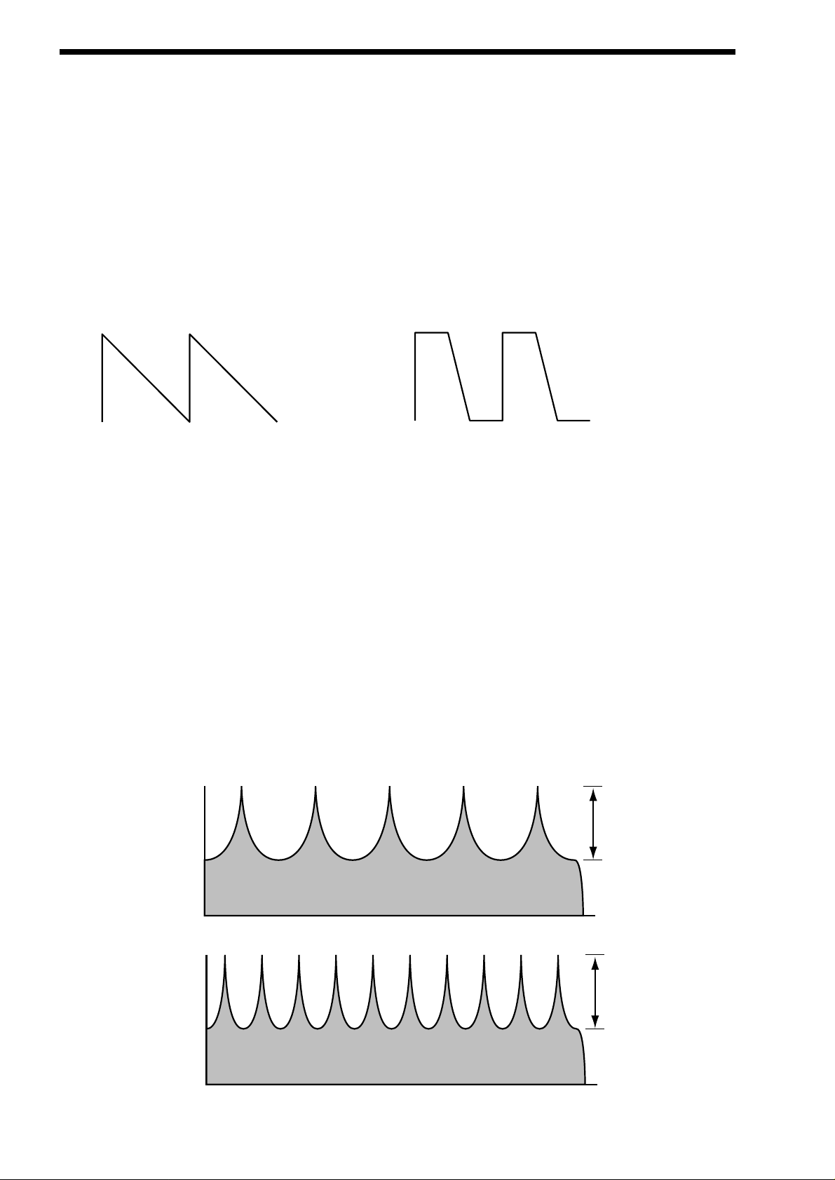
Comb Filter.
This effect is a filter that generates many peaks in the frequency response of the signal. This can be seen in the frequency
Response curve below.
18
Saw Waveform
Distorted Saw Waveform
Boost
Level
Level
Comb Filter Frequency Responce at a low "Freqency" setting
Boost
Comb Filter Frequency Responce at a high "Freqency" setting
There are many peaks & they look like a “comb” hence the name Comb Filter. There are two parameters associated with this
effect. Comb frequency controls the “frequencies” at which the peaks occur & Comb boost controls how high the peaks are. The
effect is to alter the timbre of the sound. Although similar to EQ, this effect can produce effects not possible using a standard EQ.
The resulting sound tends to be quite “Metallic” sounding especially when large “Boosts” are applied.
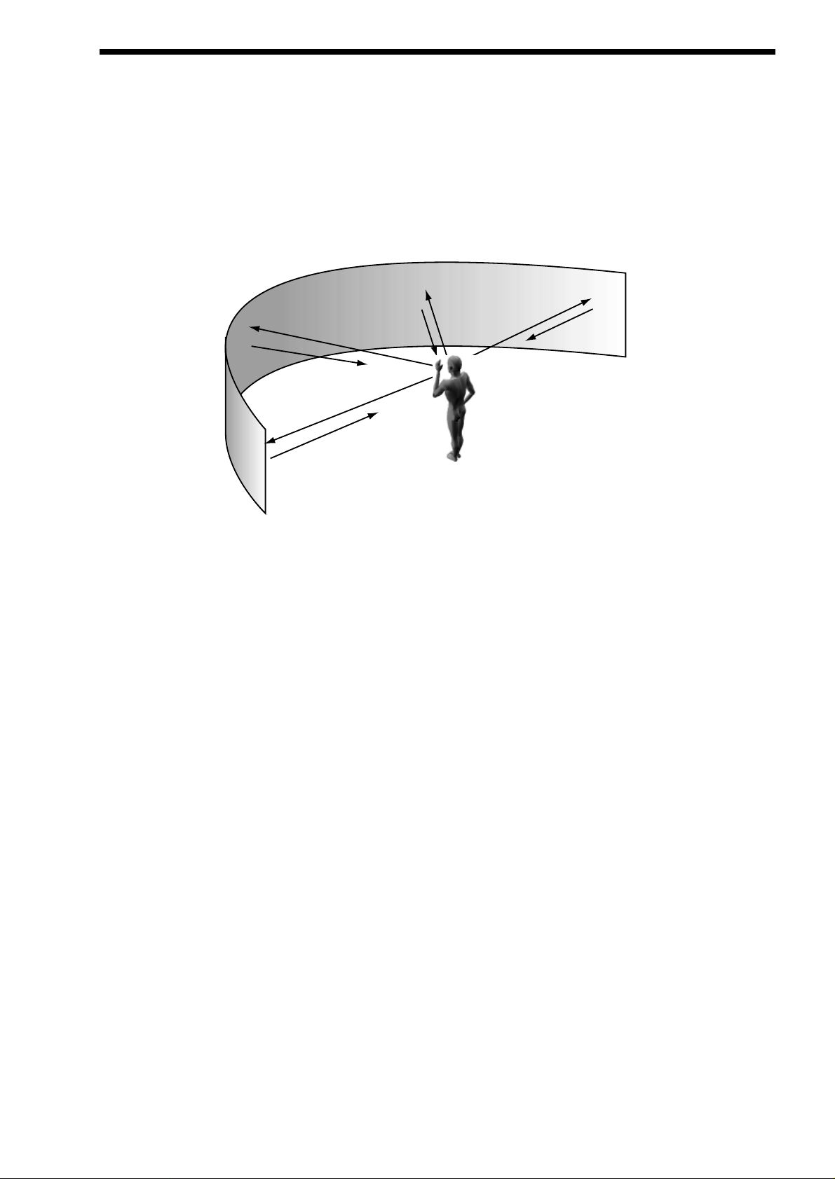
Reverb.
This is an “Acoustic Simulation of a room. Why does singing sound good in the toilet? Reverb that’s why. The Reverb Effect is a
computer model of the acoustics of a room. The type of room is up to you, anywhere from the toilet to the local Concert hall is possible. Below is a simplified diagram of the reflections of sound in a room. Note there are many reflections from all directions.
When the Reverb button is pressed, the knob in the effect section controls how much Reverb there is. Anticlockwise there is little
effect This can be thought of as being very close to the sound source within the hall. Fully clockwise there is lots & this can be
thought of as being at the other end of the hall from the sound source. Basically one way of looking at this parameter is “where you
are & where the sound source is in the hall”.
Different types of rooms & halls have different acoustics. For this reason, Nova II keyboard features several different Reverb types.
These range from very, very small rooms like the “Dry Chamber” setting to the very large hall like the “Large type 2” setting.
Additionally, “special” types have been included. These are “Gated” types & are an artificial type of reverberation that sustains for a
period & typically dies away suddenly rather than smoothly decaying away as reverb does naturally. These types can be used as a
special effect, especially on drums.
Most rooms have dominant large reflective surfaces ( Larger walls typically ) & these create dominant echoes in the reverberated
signal. Early ref ( reflection ) level simulates these reflections. Large amounts of Early ref level will produce strong signal at the
beginning of the reverb.
Decay Time is the time it takes for the Reverb to die away after the sound has stopped. This can be thought of a “what the hall is
made of”. Very acoustically reflective rooms tend to have long decay times & very non reflective rooms have short ones.
HF damp is short for High Frequency Damping. This controls the “tone” of the decaying Reverb. This can be thought of as the
amount of carpet & drapes in the hall. Carpet & drapes tend to absorb high frequencies so as a sound “bounces” around the hall ,
giving you your Reverb effect. With each bounce the sound looses a little treble. No HF Damping is a little unusual in the “real”
world but can be used to emphasise sibilant or trebly sounds. Normally a little HF Damping is applied to give the Reverb a natural
kind of sound.
Rotary Speaker/Ensemble/Chorus/Flanger/Phaser.
This is one effect that can be a Rotary Speaker, Ensemble, Quad Chorus, Chorus / Flanger or a Phaser.
Rotary Speaker - an overview.
This effect is designed to simulate the effect created by a “Leslie” cabinet often used in conjunction with an Organ such as a
Hammond B3. The effect was created by 2 separate speakers in the Leslie cabinet that are spun around independently with 2
motors. Hence the name of this effect, “Rotary Speaker”. One of the speakers in the Leslie cabinet is a “Horn” ( Tweeter ) & the
other is a “Rotor”. ( Woofer ) The effect has 2 settings, a “Fast” setting, ( where the speakers are rotating fast ) a “Slow” setting (
ABOUT EFFECTS
19

ABOUT EFFECTS
where the speakers are rotating slowly ) & a “Stopped setting”. ( where the speakers have stopped moving ) The speakers are
quite heavy so when changing from one setting to another the speed change is not instant but gradual due to the speakers inertia.
Ensemble - an overview.
This effect is designed to simulate the “Ensemble” effects found in classic “String Ensemble” keyboards like the Solina or the
Roland SE101. This is similar to Chorus in the sense that Ensemble provides an effect that fattens up sounds & provides a stereo
image but without the swirling sensation. It could in actual fact be thought of as 4 independent Choruses all running at different
speeds, thus masking the “wobbly” sensation that Chorus can produce. This is particularly suitable for string sounds as it sounds
smoother than Chorus for this purpose.
Chorus - an overview.
This is an effect originally designed to simulate the effect when many people sing together as opposed to one person or the sound
of a 12 string guitar as opposed to a 6 string guitar. Chorus is an effect that is produced by detuning the signal slightly & mixing it
back together with the original signal. The characteristic Chorus swirling effect is produced by an LFO that controls the amount of
detuning the chorus performs.
Quad Chorus.
This is a effectively 4 Choruses running at once from one LFO but in different phases. This creates a particularly “thick” Chorus
effect suitable for String Ensemble & other “Lush” sounds.
Chorus/Flanger.
.
Normal Chorus & Flanger effects are quite similar. Using this effect as a Chorus provides a Stereo effect with a smooth swirling
sensation that fattens up sounds & provides a stereo image. This type of Chorus differs from the Quad Chorus in the sense that
although not as “thick” sounding, this Chorus retains the “definition” of the effected sound making it more suitable for basses,
organs & percussive sounds. The Flanger effect is similar to a chorus but tends to use more detuning & feedback to produce an
effect with a pronounced swirling sensation that emphasises the harmonics in the sound as it sweeps through them.
Phaser.
This effect is almost the reverse of a Flanger. Asmall amount of phase shift is applied to the signal via an LFO. When this is added
back together with the original signal, a pronounced swirling effect is produced that cancels out harmonics in a sound as it sweeps
through them.
Chorus Speed. This parameter controls how fast the LFO for this effect is going. Generally a fairly slow speed is used. Higher
speeds tend to induce a vibrato like quality to the sound.
Mod Depth controls the amount of detuning or phase shift that the effects LFO produces. Again large amounts of modulation from
this parameter will produce a more noticeable effect. Generally moderate amounts are used but you will find that bass sounds benefit with more Mod Depth than normal. Feedback controls how much of the treated signal is fed back into the input. Subtle effects
like chorus benefit from low levels of feedback. Flangers & Phasers on the other hand sound better with more feedback. Feedback
emphasises the harmonics in a Flanger & emphasises the cancellation of harmonics in a Phaser.
The Type parameter determines if this effect is going to be a Chorus or a Flanger or a Phaser. Select the one you want.
The effects LFO should not be confused with the front panel Program LFOs.
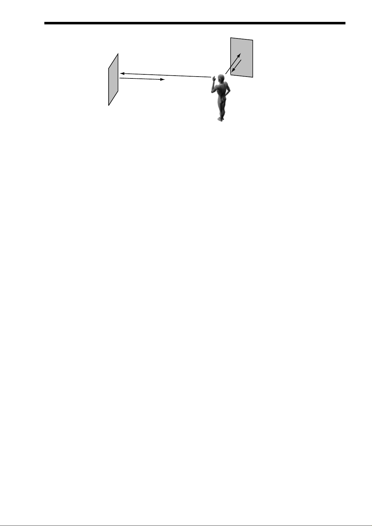
Delay.
This effect is normally a single acoustic reflection of a sound. This is commonly called Echo. This effect can be heard naturally anywhere where there is a large flat surface, like a concrete wall. A“Stereo” version can be considered to be two concrete walls & this
is the type that the Nova II keyboard uses. The distance from the walls determines the delay time & in the example below the distance between the left wall & left ear of the listener is different to the distance between the right wall & the right ear of the listener.
This creates a Stereo “staggering” effect of the echoes & is normally referred to as “Multi Tap Delay” or “Tap Delay”.
20
NOTE:
NOTE:
Delay Time. This parameter controls the amount of time it takes for the delayed signal to be heard after the original signal. In the
example given above this is the same effect as the distance you are from the wall. Alarge distance produces a long delay & a
short distance produces a short delay. In the Nova II keyboard, the Delay time is the time of the Longest delay. The shorter delay
will be a percentage of this value.
See “Ratio” below.
Feedback. This parameter controls how much of the delayed signal is fed back into the delay’s input. No feedback produces a
“Slapback Echo” effect, that is just one delayed signal with no repeats. Small amounts of feedback produce “repeated” signals giving the “Echo” effect. This can be thought of as standing in-between two parallel concrete walls. The sound bounces back & forth
between them. In this case the Decay Time represents the distance between the walls.
HF Damping. HF Damping is short for High Frequency Damping. This controls the “tone” of the decaying Echo. This can be
thought of as the amount of drapes on the walls. Drapes tend to absorb high frequencies so as a sound “bounces” from wall to wall
, giving you your Echo effect, with each bounce the sound looses a little treble. No HF Damping is a little unusual in the “real” world
but can be used to emphasise sibilant or trebly sounds. This characteristic was found in older “Tape” based echo units. Higher values of this parameter simulates the effect of worn out tape or heads in a tape echo. Normally a little HF Damping is applied to give
the Echo a natural kind of sound.
Delay Ratio. The Ratio parameter automatically adjusts the “Ratio” of the Longest Delay time & the shorter Delay time into timings
that are useful for Musical use. This parameter does not effect the Delay Time parameter but does alter the shorter Delay time so
that it works well with the Delay Time setting.
Width is the Stereo spread between the long & shorter Delay times. At a width of 0, both delays appear in the middle of the stereo
field. (Mono) At a width of 127, the long delay will appear on one output & the shorter delay on the other producing a dramatic
stereo effect.
Pan.
This effect controls where the sound “sits” in the stereo field. In the Nova II keyboard this performs exactly the same function as
Pan does on a Mixing console. It can be used to statically position a sound anywhere from Left to Right in the stereo field. This (
as everything else on Nova II keyboard ) can be controlled via MIDI controllers.
Pan Typedetermines if the Pan is set to Pan automatically. If set to “Autopan” the sound will swing from side to side of the stereo
field at a rate determined by the Speed parameter. If set to “Tremolo” the sound goes up & down in volume at a rate determined by
the Speed parameter.
Pan Speed determines the speed of the Autopan & Tremolo effects.
Pan Depth determines how much the Autopan & Tremolo effects control the Volume of the sound, small amounts produces subtle
movements & full amount produces change from no sound to full volume.
ABOUT EFFECTS
21

NOVATIONISH - NOVATION JARGON
ATranslation of terms used throughout this manual.
In this manual there are several terms used that may lead to confusion if not fully understood. Below is an explanation of all the
Novationish used in this manual
Program
This is the simplest type of sound Nova II keyboard can create. These are accessed by pressing the Program button.
Other Manufacturers sometimes call these Patches or Partials.
Drum Map
This is the special arrangement where many Programs are arranged across the keyboard ( one for each note ) & are all accessed
simultaneously. The Drum Maps are accessed by pressing the Program button & the Bank buttons. Other Manufacturers sometimes call these Drumkits.
Performance
This is the most complex type of sound Nova II keyboard can create. It is made up of 6 different sounds called Parts. These Parts
can be layered or set up as splits to form the Performance. Performances are accessed by pressing the Performance button. Other
Manufacturers sometimes call these Multis, Multisetups or Combinations.
Part
This is one of the 6 sounds or Parts of a Performance. The sound assigned to a Part is called a Program.
Other Manufacturers sometimes call these Timbres.
Favourites
This is a special set of memories storing all your “Favourite” Programs & Performances These are accessed by pressing the
Favourites button.
Voice
This is a measurement of polyphony. One voice is the equivalent of one note being played. One voice in the Nova II keyboard uses
three Oscillators, two Ring Modulators & a Noise generator as sound sources. All these sound sources can be used simultaneously
in one Voice.
Oscillator
This is the basic waveform generator in the Nova II keyboard. As described above there are three Oscillators per Voice.
Sync Effect
This is a parameter of one oscillator that simulates the “Sync Effect” generated by 2 Analogue oscillators in a “Oscillator Sync” configuration. For more details refer to page 7 - About Analogue Synthesis.
Hardness Effect
This is a parameter that controls the harmonic content of any waveform. Full Hardness Effect on a waveform produces a normal
wave. Minimum Hardness produces an near sine wave. This is similar to having a separate LPF for each oscillator. For more
details refer page 9 - About Analogue Synthesis.
Analogue Sound Modelling™
This is the Synthesis System the Nova II keyboard uses to create sound. Created by Novation, this new method of synthesis was
first used in the Award winning Novation Drum Station.
When this symbol appears in the manual this indicates an important feature, or a destructive function such as Writing data to memory etc.
22
NOTE:
NOTE:

There are 3 types of “Sounds” you can select in the Nova II keyboard. These are Programs, Drum Maps & Performances.
When the Program Button is selected a single Program is recalled from memory. AProgram is the most basic type of sound in the
Nova II keyboard. This sound is made up of the 3 oscillators, the 2 ring modulators & the noise generator. These are Mixed together & are fed through the Filter, Amplifier & effects processors. The sound produced by a Program in Program Mode comes out of
outputs 1 & 2. AProgram uses the “Global MIDI Channel” to receive MIDI Data. A Program covers the entire range of notes on a
keyboard & has the standard velocity curve. On other synthesisers, a “Program” is sometimes referred to as a “Patch” or “Partial”.
This is fairly standard amongst synthesisers except the Nova II keyboard differs in 2 areas.
Firstly, the Effects Section is memorised with the Program. Although this may seem standard in comparison to other equipment, the
real difference happens when a Performance is selected. Because the Nova II keyboard can run 42 Effects at once, all 6 “Parts” of
a Performance have their own Effects Section. This allows all the “Parts” of a Performance to sound exactly the same in
Performance mode as they do in Program mode. This is unique to the Nova II keyboard & is literally like having the equivalent of 6
separate synthesisers with 6 sets of effects sections allowing a very high level of production to be achieved with just one box.
Secondly, the Arpeggiator Sections parameters are also memorised with a Program. Similarly because the Nova II keyboard can
run 6 Arpeggiators at once, all 6 “Parts” of a Performance have their own Arpeggiation.
Below is a simplified block diagram of a “Program” in the Nova II keyboard.
In a Program, incoming MIDI messages get processed by the Arpeggiator ( If it is “On” ) & control the Oscillators. The signals produced are mixed together in the Mixer section & the resulting signal is passed on to the Filter. The signal then is passed to the
Amplifier which then sends the signal into the effects section. This signal path is refected on the front panel of the Nova II keyboard
allowing easy understanding of the synthesis process. All the essential controls of this process are on the front panel & in Program
mode, adjusting the controls will directly effect the sound produced. For a deeper understanding of the creation of sounds refer to
the section “About Analogue Synthesis” on page 6 for details.
Arpeggiator Oscillators
and Ring
Modulators
Mixer Filter Amplifier
Dist EQ
Pan
Reverb
Chorus
Delay
LFO 2
Envelope 2
Envelope 1LFO 1
Envelope 3
MIDI
Program
Comb
Effect Section
( Shown in Normal
Configuration, D + R + C )
ABOUT PROGRAMS
23

ABOUT DRUM MAPS
ADrum Map is a special way of playing Programs. Normally a Program is transposed & is played over the entire range of the keyboard. In a Drum Map each program is assigned to a single note on the keyboard & every note from C1 ( bottom C on the keyboard ) to B4 plays a different program. Basically a separate “Program” is assigned to each note in a Drum Map. This allows the
keyboard to access different Drum sounds on each key. This is particularly useful when using the Nova II keyboard with a
sequencer as a Drum Map can be assigned to a single “Part” of a Performance allowing many different drums to be played on one
MIDI channel. Each Drum Map contains 50 Programs. Below is a block diagram of a Nova II keyboard Drum Map.
The incoming note data is split up & fed to one of the 50 Programs in the Drum Map. These programs are 000 to 49. Drum Map
Programs 000 to 048 are for storing sound data. The output of all these programs is mixed together & fed through one effects section. The effects sections parameters are stored in Drum Map Program 049, however adjusting the effects section of any Program
within a particular Drum Map will alter the effects on Drum Map Program 049 & hence the whole Drum Map. When a Drum Map
program is saved the sound data is stored in the desired location & any edits to the effects data is stored in Drum Map Program
049. Effects settings from other programs can be imported into a Drum Map by saving the Program that has the desired effects in
Drum Map Program 49.
In the Nova II keyboard there are 4 Drum Maps.
Adjusting the effects of any Drum Map Program will affect all the sounds in the entire Drum Map.
Any Program written into Drum Map location 049 will not make a sound but will write the source Programs effects on the entire
Drum Map.
It is possible to write a “normal” type of Program into a Drum Map & write a Drum Map Program into a “normal” Programs location
using write procedure.
24
Drum Bank Program a000
Drum Bank Program a048
Dist EQ
Comb
Pan
Reverb
Chorus
MIDI
Drum Bank Program a049
Effects section
Effect Section
( Shown in Normal
Configuration, D + R + C )
Drum Bank
Delay
NOTE:
NOTE:
NOTE:
NOTE:
NOTE:
NOTE:
APerformance is a more complex arrangement where several Programs can be used at once. This allows the creation of much
more complex sounds that are either layered together to create a “Fatter” sound or a Split of 2 or more sounds on the keyboard. In
fact a Performance consists of up to 6 “Parts”. Each one of the parts can have its own Program & as explained before this means
each “Part” has its own Effects Section & Arpeggiator. This means it is possible to layer up to 6 Programs or create a 6 way split of
different sounds across the keyboard or any combination of the two. Below are some examples.
In the Performance Layer example there are 2 Pad Programs layered together over the entire range of the keyboard. Playing any
one note will play both the sounds on that note. In the Velocity Crossfadeexample playing the keyboard softly will mean Pad 1 is
heard, playing the keyboard hard & Pad 2 will be heard, playing the keyboard with medium feel will produce a mixture of Pad 1 &
Pad 2.
In the Performance Split example, play the higher end of the keyboard & Pad 1 will be heard. Play the low end & Pad 2 will be
heard. Additionally to this, it can be seen that different Arpeggiators are assigned to the Lower & Upper parts of the keyboard. Both
of these can be played at the same time. The Performance Multiple example is much more complex, a Performance can have 6
“Parts”, in this case 7 have been used. The lower half of the keyboard is a 3 way layer of Programs. There is a Pad, a Bass & an
Arpeggiated 303 sound. These all sound at the same time when a note is pressed within their range. Alittle further up the keyboard
a Brass sound has been assigned & when the keyboard is struck hard a Ring mod FX is added. Further up the keyboard still there
are 2 Arpeggiated sounds assigned. They are arranged in a Velocity crossfade so that playing the keyboard in this range softly produces a Spike sound with an Arpeggiation & playing it heavily produces a Bell sound with a different Arpeggiation. To set the split
points use the “Range” Parameter to specify over which “Range” of notes the selected “Part” will sound. To set the velocity crossfades use the “Velocity Curve” Parameter to specify how the selected “Part” will respond to velocity.
Performance mode is also the mode in which you can use Nova II keyboard “Multitimbrally”. This allows Nova II keyboard to play
up to 6 different sounds simultaneously on 6 different MIDIChannels. Each “Part” of a Performance can have a separate MIDI
channel setting. This is how you use the Nova II keyboard Multitimbrally.
Bell
Arpeggiator
Brass
Ring FX
Arpeggiator
Spike
Master Keyboard / Workstation
Keyboard Range
Velocity = 127
Velocity = 1
PERFORMANCE SPLIT EXAMPLE
Pad 1
Pad 2
Arpeggiator
Arpeggiator
Master Keyboard / Workstation
Keyboard Range
Velocity = 127
Velocity = 1
PERFORMANCE MULTIPLE EXAMPLE
303
Arpeggiator
Pad
Bass
Master Keyboard / Workstation
Keyboard Range
Velocity = 127
Velocity = 1
Pad
Pad 1
Pad 2
PERFORMANCE LAYER EXAMPLE
Master Keyboard / Workstation
Keyboard Range
Velocity = 127
Velocity = 1
PERFORMANCE VELOCITY CROSSFADE EXAMPLE
Pad 1
Pad 2
ABOUT PERFORMANCES
25
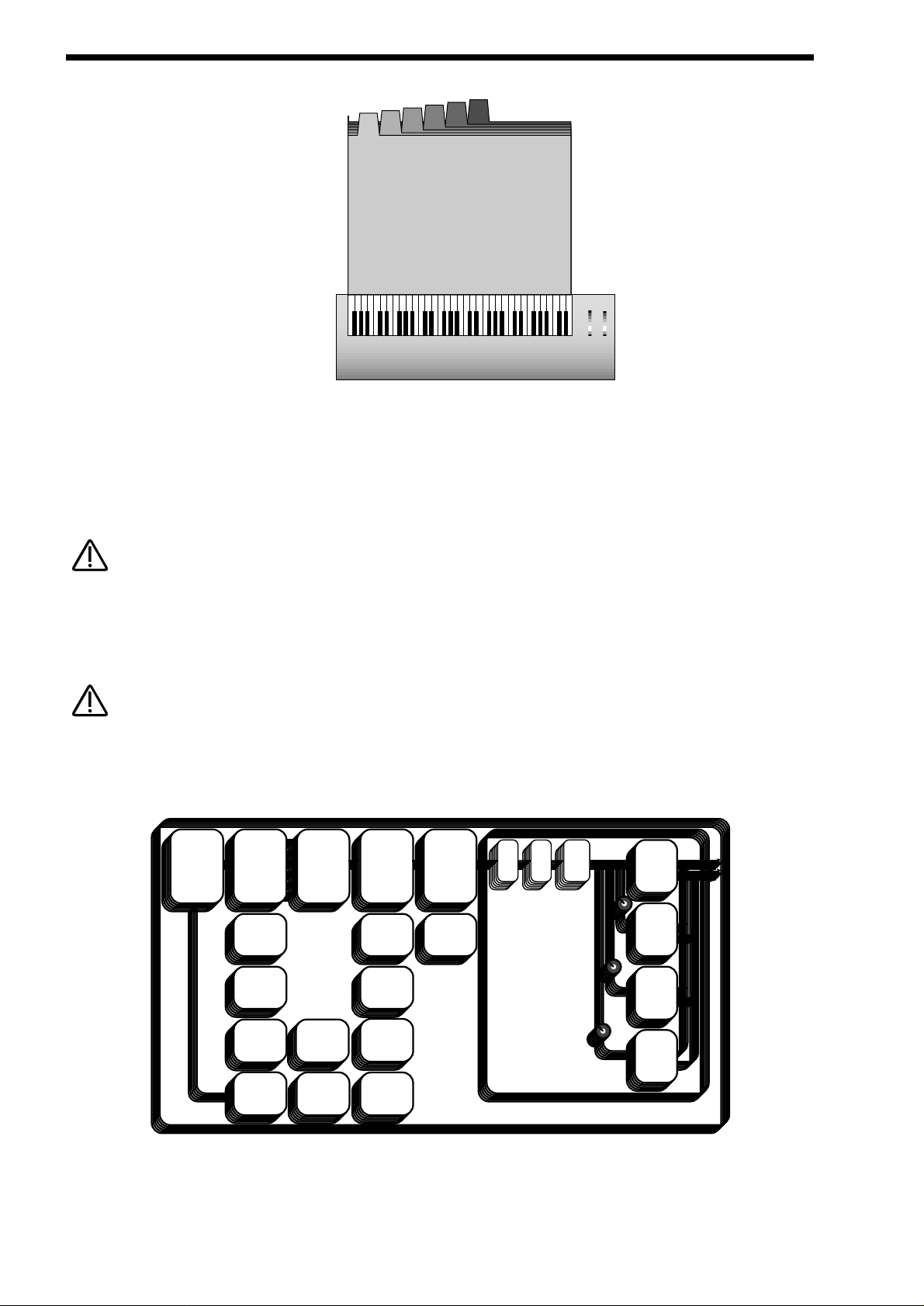
ABOUT PERFORMANCES
Above is an example of 6 different sounds assigned to 6 different MIDIChannels. Set the individual “Parts” to the required MIDI
channels & make sure the “Part” Ranges are set to cover the full range of the keyboard & Velocities are set to the normal setting
otherwise unexpected results may occur. Also it can be seen that combinations of Multitimbral & Split/Layered Performances can
be made, for example a performance could be set up so that parts 1 to 4 were assigned to MIDI Channels 1 to 4 & part 5 & 6
assigned to MIDI channel 5 with key ranges set for parts 5 & 6 so that a split is created.
When a Program change message is received on the Global MIDI channel it will change the selected Program or Performance. If a
Program change is received on a Part MIDI Channel that is not the Global one it will change the assigned Program for that Part.
When it does so the effects settings stored in the Program will be loaded into the Parts Effects section if the Effects used parameter in the Output menu is set to “Program” . If this parameter is set to “Performance” the Program will change but the effects setting
for that part will not be altered. Additionally the Arpeggiator Parameters from the Program will be loaded into the Part’s Arpeggiator.
There is only oneArpeggiator Speed control in a Performance. Adjusting the speed of any Parts Arpeggiator will control all 6
Arpeggiators.
Below is a simplified block diagram of a “Performance” in the Nova II keyboard.
APerformance is literally a duplication of 6 Programs, including the Effects Sections & the Arpeggiators.
Arpeggiator Oscillators
and Ring
Modulators
Mixer Filter Amplifier
Dist EQ
Pan
Reverb
Chorus
Delay
LFO 2
Envelope 2
Envelope 1LFO 1
Envelope 3
MIDI
Tune
Velocity
Output
Range
Polyphony
Performance
Comb
Effect Section
( Shown in Normal
Configuration, D + R + C )
26
Velocity = 127
M Ch1
Part 6
M Ch6
Part 5
M Ch5
Part 4
M Ch4
Part 3
M Ch3
Part 2
M Ch2
Part 1
Part 1
M Ch1
Velocity = 1
Master Keyboard / Workstation
Keyboard Range
MULTI TIMBRAL PERFORMANCE EXAMPLE
NOTE:
NOTE:
NOTE:
NOTE:
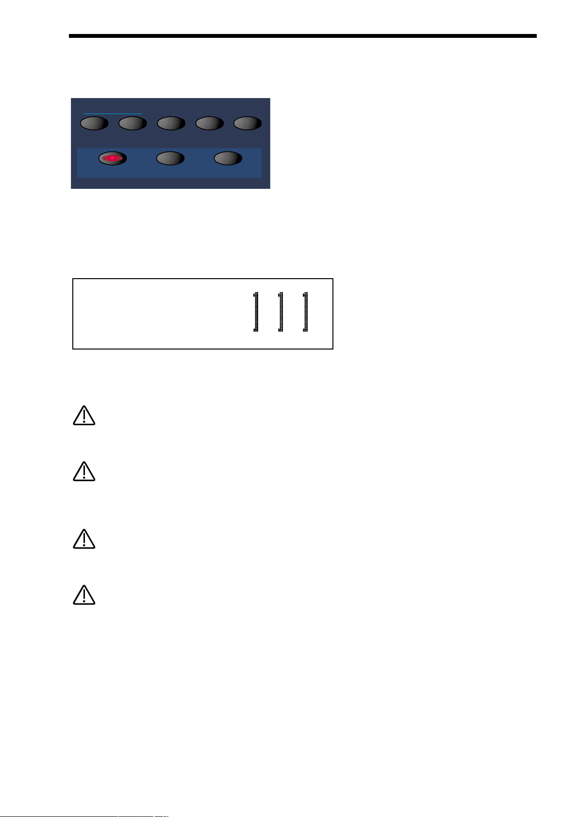
The Nova II keyboard features a “Favourites Section” that allows any 2 button selection made on the Keypad section or any incoming MIDI Program Change command to call up any Program or Performance from any Bank, or select a new Arpeggiator Pattern
for the currently selected program. The Favourites Section is user programmable & is Memorised as Global.
To select the Favourites Section simply press the Favourites button in the Mode section or send a MIDI Bank Message of 0 (
Controller 32 with a value of 0 ).
To select a Favourite requires a maximum of only 2 button presses, even if the number has 3 digits. For example to select
Favourite 111, make sure the Nova II keyboard in in the Favourites mode (the Favourites button is lit ), & simply press the 110 button & the 1 button in the Keypad section & the display shows:
To select Favourite 001, make sure the Nova II keyboard in in the Favourites mode ( the Favourites button is lit ), & simply press
the 0 button on the top row of the Keypad section & the 1 button on the bottom row of the Keypad section. In some cases only one
button press is required, for example if Favourite 111 is currently selected, to select 112 only requires the 2 button to be pressed.
The Favourites map can be made active via MIDI at all times by setting the “Incoming program change” parameter on page 13 of
the Global mode to “Favourites”.
The Favourites mode can be memorised as the power up default made by saving the Global data when this mode is selected. This
allows Master Keyboards trying to control the Nova II keyboard which do not transmit Bank Select Messages to be able to call up
any Program or Performance in any Bank.
When a Program/Part receives a valid Bank Select Message (Controller 32) via MIDI IN, the bank will continue to remain selected
for the Program/Part until another Bank Select Message is received via MIDI IN.
This “Favourites” mode is assigned to MIDI Bank 0( Controller 32 with a value of 0 ). If this message is received the Nova II keyboard will switch from normal operation to the Favourites mode. Any Program changes received after that will be re-mapped
according to the Favourites map. This can be disabled by sending another MIDI Bank Message calling up either one of the
Program or Performance Banks. See page 137 for details on the Bank Messages received by Nova II keyboard.
ABOUT FAVOURITES
27
demo tracks
program
compare writefind global
performance
assign
favourites
favourites
Pianola M-wh
Prog A111 Fave
NOTE:
NOTE:
NOTE:
NOTE:
NOTE:
NOTE:
NOTE:
NOTE:
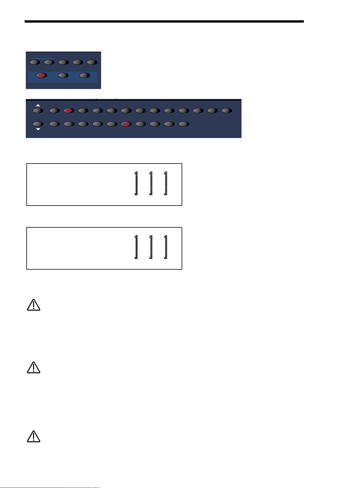
ASSIGNING FAVOURITES
To assign a Program or performance to a specific Favourites location is easy. Simply select the desired Program or performance
using the Program or Performance buttons in the Mode section, the Bank buttons & keypad section.
Now press the Assign (favourites ) button in the Mode section & it will light to show it is active. Select the Destination “Favourite”
while in this mode by pressing the appropriate flashing buttons on the keypad. The display will show:
Press the Assign (favourites) button again & the display shows this message momentarily:
Indicating that the program has been assigned to Favourite 111. It is possible to assign all your “Favourites” in this way but the
assignments are not actually written to Flash memory until a write procedure has been done. Now to write this into flash press the
Favourites button to enter the Favourites mode & press the Write button.
If the Write button is not pressed while in Favourites mode the Flash memory will not be written & all assignments will be lost on
power off.
It is also possible to assign Arp Patternchanges to Favourites. To do this enter the Arp menu & go to page 1 where the display
shows the Pattern bank & Pattern Number parameters. Select the Bank & Pattern to be assigned. Press the Assign Favourites button & set the Favourites location for the Pattern assignment using the Keypad buttons. Press the Assign button again to confirm
the assignment. Press the Write button to write the assignment to Flash memory.
If the Write button is not pressed while in Favourites mode the Flash memory will not be written & all assignments will be lost on
power off.
It is also possible to assign “Current” program changes to Favourites. “Current” means a program or performance will be selected
at a specified location within the “Currently” selected bank. You could think of this as Favourite that is just a program change without the bank change data. To do this enter the Favourites mode. Select the desired “Current” value with the keypad section. Press
the Assign Favourites button & set the Favourites location for the Current assignment using the Keypad buttons. Press the Assign
button again to confirm the assignment. Press the Write button to write the assignment to Flash memory.
If the Write button is not pressed while in Favourites mode the Flash memory will not be written & all assignments will be lost on
power off.
28
demo tracks
program
bank
compare writefind global
performance
assign
favourites
favourites
90 100 110 1200 1020304050607080
9012345678
Assign
program to :
Program
assigned to :
NOTE:
NOTE:
NOTE:
NOTE:
NOTE:
NOTE:
 Loading...