

NorthStar LITE Applications Manual
NorthStar LITE Battery
Application Manual

Lithium Ion
Page
Section
Title
3
1
Introduction
4
2
Operation
7
3
Useful Life
8
4
Installation and Handling
13
5
Maintenance
13
6
Transport
13
7
Technical Specifications
14
8
Contacts
3
1 Introduction
1.1 LITE Lithium Battery Technology
The LITE Battery Unit has been specifically designed for
demanding applications such as telecom, energy storage,
renewable energy and hybrid power solutions. NorthStar
LITE delivers high energy density and excellent cyclic
endurance without compromising safety. Each Battery Unit
consists of lithium-ion cells and a battery management
system, BMS, encased in an outer housing.
The LITE Battery Units are designed to fit in a 19” rack.
Up to ten (10) Battery Units can be connected in parallel to
increase the available energy. The LITE Battery Units can
operate in combination with lead acid batteries, even
when the charge voltage is low and no boost voltage
functionality is available. The system is also designed for
re-use of existing site cabling and accommodates dual M8
cable lugs (commonly available for AGM batteries).
1.1.1 Battery Cell
The LITE Battery Unit is based on a Li-ion cell with the
lithium iron phosphate (LFP) chemistry. LFP offers
exceptional lifetime, high specific power and cyclic
endurance in combination with good safety characteristics.
The battery cells utilized in the Battery Unit are of
prismatic type with laser-welded aluminum casings. Each
cell has a safety vent, which enables the release of overpressures in case of a thermal runaway situation.
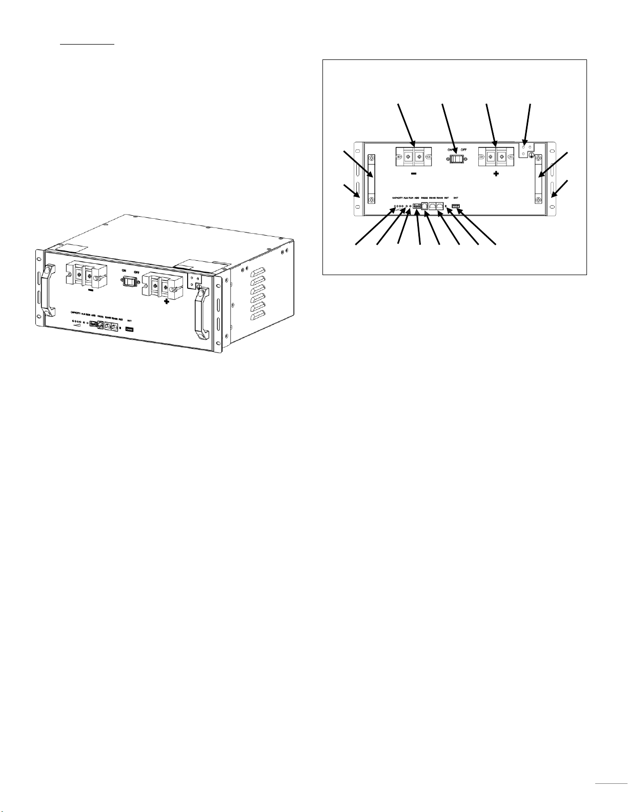
1.1.2 Front Panel
1 Negative terminal
2 Circuit Breaker, CB
3 Positive terminal
4 Grounding point.
5 Handles
6 Fastening bracket for 19”-racks
7 Capacity, see chapter 2.4 for more information on
behavior.
8 Alarm, see chapter 4.5 for more information on
behavior.
9 Run, see chapter 4.5 for more information on
behavior.
10 ADD, Address extension Dip switch, see chapter 4.4.2
for more information.
11 RS232. RS232 communication port is used to upload
data from BMS to a monitoring system.
12 RS485. RS485 communication port is used for
communication between batteries and to upper host.
For more information see 4.5
13 Reset, RST. The reset button can be used to recover
the Battery unit.
14 Dry contact
1.2 Definitions
The definition for each of the following terms or
abbreviations describes the context employed throughout
this document.
Battery unit: Functional unit for storage of electrical power
with a nominal voltage of 48 V.
BMS: Battery management system.
2 1 14
13 4 5 7 8 9 12
10
11 3 5 6 6
4
C-Rate: Current normalized to the rated capacity of a
battery.
Cut-off temperature: Temperature where the BMS will
terminate the usage of the Battery Unit
Cut-off voltage: Voltage where the BMS will no longer
allow usage of the Battery Unit.
EOL: End-of-Life, as definition it states when less than
80 % of the initial capacity remain. Li-ion can be used for
lower remaining capacity.
LFP: Lithium iron phosphate, electrode material used in the
LITE Battery Unit.
SoC: State-of-charge, fraction of rated capacity, 0-100 %.
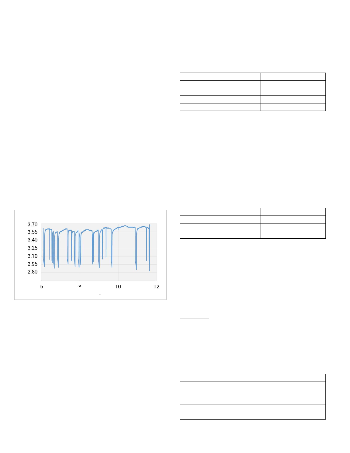
1.3 Unstable Mains Service
Where the main electrical supply is of poor quality, the
batteries are used to provide service when the mains is off.
Common to the poor grid operation are frequent
interruptions. Often the time between the interruptions is
short which means that the battery will not be fully
charged. This is not a problem for lithium-ion batteries, as
they have a stable performance, independent of SoC. The
figure below shows the voltage of battery units in unstable
mains.
2 Operation
2.1 GENERAL PRECAUTIONS
Only operate within specified temperature, current and
voltage. All data from battery shall be stored in an upper
host computer for future reference.
2.2 BMS
The NorthStar LITE Battery Unit is equipped with an
internal BMS in every unit. The BMS will protect the
battery from operating outside of its safe operating
window by monitoring cell voltages, currents, SoC, capacity
and temperatures. The BMS also include cell balancing
functionality, reverse polarity protection, charge control,
high/low temperature cut off, regulated slow charge, and
the optional heater on/off.
2.2.1 Protection functions
Overvoltage
Overvoltage
System
Cell
Rated charging voltage
52.5V
Overcharge alarm
54.0±0.5V
3.6±0.02V
Overcharge protection
54.6±0.5V
3.65±0.02V
Overcharge recovery
50.2±0.5V
3.4±0.02V
If the system voltage or cell voltage becomes higher than
the overcharge protection voltage for more than 2 seconds,
the BMS enters overcharge protection state and inhibits
charging.
The overcharge protection delay is 1 ± 0.5 s and the
overcharge protection release conditions are one of the
following:
The voltage is below the recovery voltage or
Switch to discharge mode.
Undervoltage
Undervoltage
System
Cell
Overdischarge alarm
39.0±0.5V
2.6±0.02V
Overdischarge protection
37.5±0.5V
2.5±0.02V
Overdischarge recovery
43.5±0.5V
2.9±0.02V
If the system or cell voltage becomes lower than
overdischarge protection voltage and stays at that voltage
longer than 2 seconds, the BMS enters overdischarge
protection state and inhibits discharging.
The overdischarge protection delay is 1 ± 0.5 s and the
overdischarge protection release condition is:
Start charge mode.
Sleep mode: If undervoltage protection on system level or
cell level is detected, the BMS goes into sleep mode.
Release conditions are one of the following:
Put in charge or
Activated via RS232 communication or
Reset button pressed
Overcurrent
Overcurrent
System
Charging Overcurrent alarm
102±3A
Charging Overcurrent protection
105±4A
Discharging Overcurrent alarm
102±3A
Discharging Overcurrent protection
105±4A
Short circuit current protection
210±10A
Voltage of battery in unstable mains
Time [Days]
Cell]
5
If the charging current becomes more than the charge
overcurrent protection current is limited to 10A.
Overcurrent protection:
The overcurrent protection delay is 4±1 s.
Charge overcurrent protection is released
immediately, no delay, when discharge is started.
Short-circuit protection:
The short circuit protection delay is 300 µs or
faster.
The short circuit protection state can be released by
pressing the button to reset the system. It is then
necessary to remove the load first.
Over temperature
Over temperature
System
Cell
Charge, Over temperature alarm
55±2°C
55±2°C
Charge, Over temperature protection
60±2°C
60±2°C
Charge, Over temperature recovery
45±2°C
45±2°C
Discharge, Over temperature alarm
55±2°C
55±2°C
Discharge, Over temperature
protection
60±2°C
60±2°C
Disharge, Over temperature recovery
45±2°C
45±2°C
If the maximum cell temperature becomes higher than cell
overtemperature protection threshold, BMS enters cell
overtemperature protection state and inhibits charging
and discharging.
If the cell temperatures return to the normal temperature
range, the temperature protection is released, then the
system restores charge and discharge respectively.
Under temperature
Under temperature
System
Cell
Charge, Under temperature
alarm
5±2°C
5±2°C
Charge, Under temperature
protection
0±2°C
0±2°C
Charge, Under temperature
recovery
8±2°C
8±2°C
Discharge, Under temperature
alarm
5±2°C
5±2°C
Discharge, Under temperature
protection
-20±2°C
-20±2°C
Discharge, Under temperature
recovery
-10±2°C
-10±2°C
If the minimum cell temperature becomes lower than cell
under temperature protection threshold, BMS enters cell
under temperature protection state and inhibits charging
and discharging.
If all of the cell temperatures return to the normal
temperature range, the cell temperature protection is
released, and then the system restores charge and
discharge respectively.
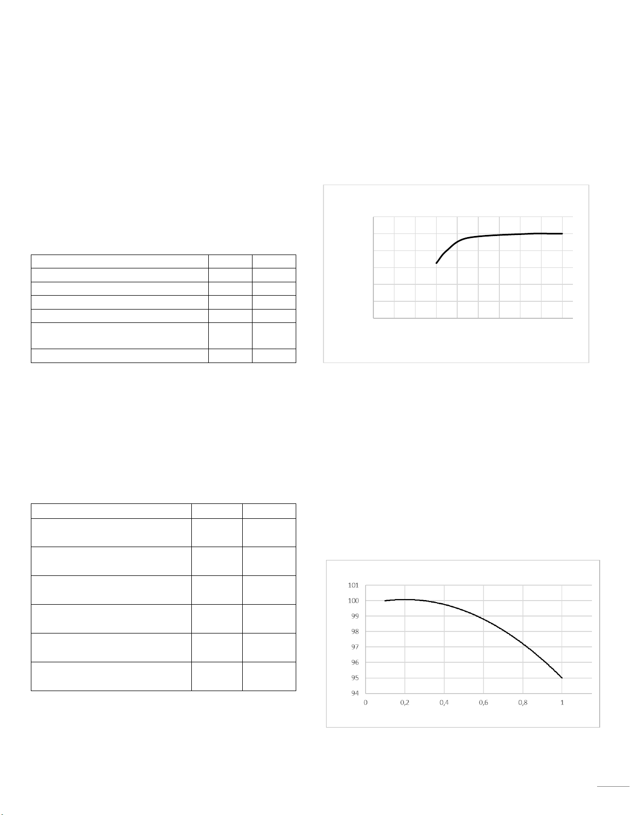
2.3 Capacity
The rated capacity of Battery Unit is stated in the datasheet.
The available capacity of the system will be dependent on
the battery temperature and the current, see example
below.
2.3.1 C-Rate
In this document, charge and discharge rates are expressed
as C-rates. C-rate is the current normalized to the rated
capacity of a battery.
Example: 1C represents the current required to discharge a
battery in one (1) hour. 0.1C (which can also be written as
C/10) is the current required to discharge a battery in ten
(10) hours.
Example of available capacity in different C rates in the
below figure.
0
20
40
60
80
100
120
-35 -25 -15 -5 5 15 25 35 45 55
Capacity [Ah]
Temperature [°C]
Available Capacity @ different temperatures
Available capacity
Discharge Rate [C]
 Loading...