

www.northstarnav.com
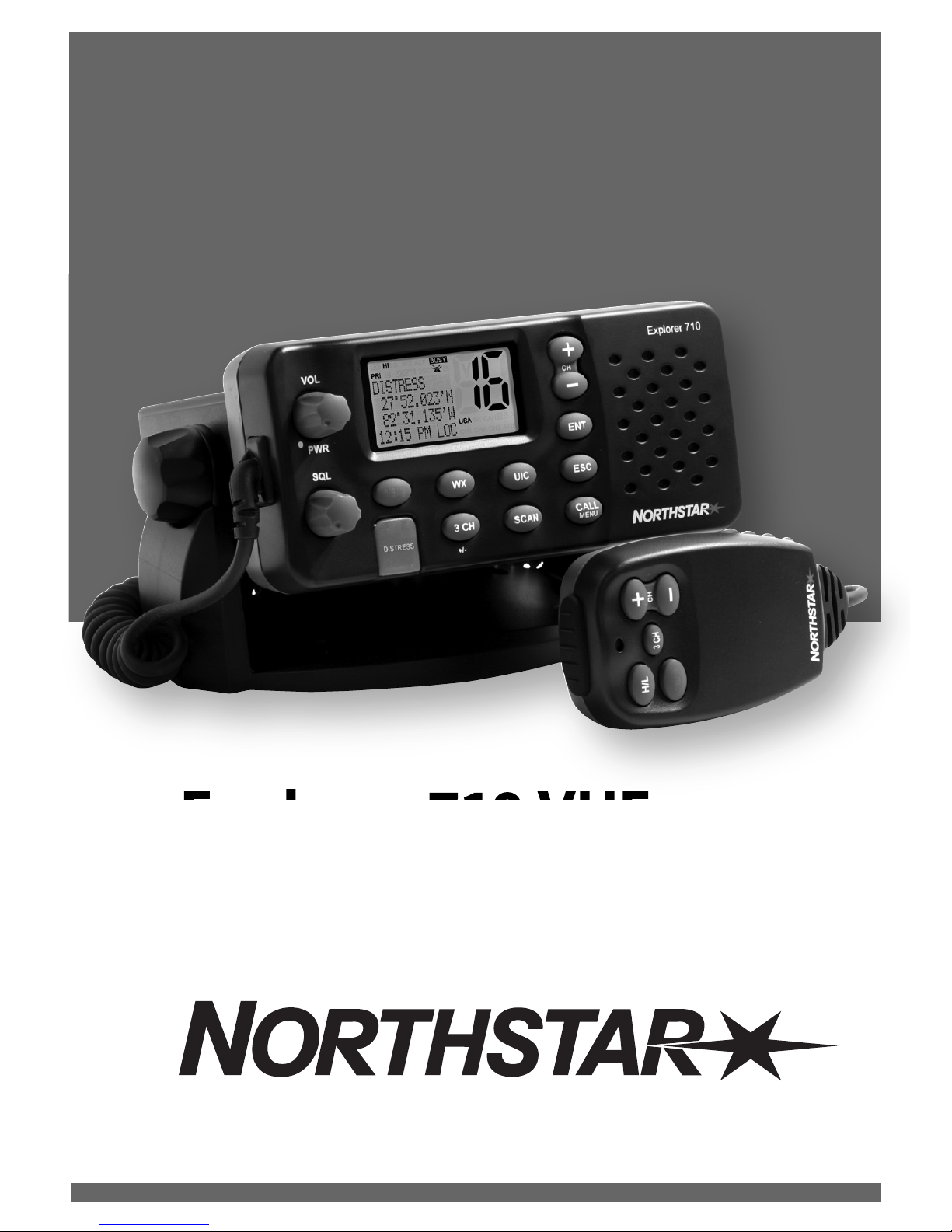
Explorer 710 VHF
VHF Marine Radio
Operation and Installation Manual
2 Northtstar Explorer VHF Series: 710US, 710EU Operation and Installation Manual
FCC Statement
Note: This equipment has been tested and found to comply with the limits for a Class B digital device,
pursuant to Part 15 of the FCC Rules. These limits are designed to provide reasonable protection against
harmful interference in a normal installation. This equipment generates, uses and can radiate radio
frequency energy and, if not installed and used in accordance with the instructions, may cause harmful
interference to radio communications. However, there is no guarantee that interference will not occur in
a particular installation. If this equipment does cause harmful interference to radio or television reception,
which can be determined by turning the equipment off and on, the user is encouraged to try to correct
the interference by one or more of the following measures:
Reorient or relocate the receiving antenna.
Increase the separation between the equipment and receiver.
Connect the equipment into an output on a circuit different from that to which the receiver is
connected.
Consult the dealer or an experienced technician for help.
A shielded cable must be used when connecting a peripheral to the serial ports.
IMPORTANT SAFETY INFORMATION
Please read carefully before installation and use.
This is the safety alert symbol. It is used to alert you to potential
personal injury hazards, Obey all safety messages that follow this symbol to
avoid possible injury or death.
WARNING indicates a potentially hazardous situation which, if not avoided,
could result in death or serious injury
CAUTION indicates a potentially hazardous situation which, if not avoided, could
result in minor or moderate injury.
CAUTION used without the safety alert symbol indicates a potentially
hazardous situation which, if not avoided, may result in property damage.
DISCLAIMER: It is the owner’s sole
responsibility to install and use the instrument
and transducers in a manner that will not cause
accidents, personal injury or property damage.
The user of this product is solely responsible for
observing safe boating practices.
BRUNSWICK NEW TECHNOLOGIES INC. AND ITS
SUBSIDIARIES AND AFFILIATES DISCLAIM ALL
LIABILITY FOR ANY USE OF THIS PRODUCT IN A
WAY THAT MAY CAUSE ACCIDENTS, DAMAGE OR
THAT MAY VIOLATE THE LAW.
Governing Language: This statement,
any instruction manuals, user guides and
other information relating to the product
(Documentation) may be translated to, or
has been translated from, another language
(Translation). In the event of any conflict
between any Translation of the Documentation,
the English language version of the
Documentation will be the official version of the
Documentation.
This manual represents the Explorer 710
as at the time of printing. Brunswick New
Technologies Inc. and its subsidiaries and
affiliates reserve the right to make changes to
specifications without notice.
Copyright © 2006 Brunswick New Technologies
Inc. Northstar™ is a registered trademark of
Brunswick New Technologies Inc

3Northtstar Explorer VHF Series: 710US, 710EU Operation and Installation Manual
Contents
Section 1 - General Information ...............................................................................................................5
1-1 Features . . . . . . . . . . . . . . . . . . . . . . . . . . . . . . . . . . . . . . . . . . . . . . . . . . . . . . . . . . . . . . . . . . . . . . . . . . 5
1-2 Customizing your Northstar VHF Radio . . . . . . . . . . . . . . . . . . . . . . . . . . . . . . . . . . . . . . . . . . . 5
1-3 How to Display and Navigate Menus . . . . . . . . . . . . . . . . . . . . . . . . . . . . . . . . . . . . . . . . . . . . . .6
1-4 How to Enter Alphanumeric Data . . . . . . . . . . . . . . . . . . . . . . . . . . . . . . . . . . . . . . . . . . . . . . . . . 6
1-5 LCD Symbols and Meanings . . . . . . . . . . . . . . . . . . . . . . . . . . . . . . . . . . . . . . . . . . . . . . . . . . . . . . 6
1-6 Basic Operation and Key Functions . . . . . . . . . . . . . . . . . . . . . . . . . . . . . . . . . . . . . . . . . . . . . . . 8
Section 2 - The Radio Menu (MENU)
.............................................................................................. 11
2-1 Radio Menu Options (Menu) . . . . . . . . . . . . . . . . . . . . . . . . . . . . . . . . . . . . . . . . . . . . . . . . . . . . 11
2-2 Maintain Your Buddy List (BUDDY LIST) . . . . . . . . . . . . . . . . . . . . . . . . . . . . . . . . . . . . . . . . . . 12
2-3 Local or Distance Sensitivity (LOCAL/DIST) . . . . . . . . . . . . . . . . . . . . . . . . . . . . . . . . . . . . . . 13
2-4 Backlighting (BACKLIGHT) and Contrast (CONTRAST) . . . . . . . . . . . . . . . . . . . . . . . . . . . . 13
2-5 GPS Data and Time (GPS/DATA) . . . . . . . . . . . . . . . . . . . . . . . . . . . . . . . . . . . . . . . . . . . . . . . . . . 14
2-6 GPS Simulator (SIMULATOR) . . . . . . . . . . . . . . . . . . . . . . . . . . . . . . . . . . . . . . . . . . . . . . . . . . . . . 17
2-7 Reset to Factory Defaults (RESET) . . . . . . . . . . . . . . . . . . . . . . . . . . . . . . . . . . . . . . . . . . . . . . . . 17
Section 3 - Radio Setup Menu (RADIO SETUP) ........................................................................................... 18
3-1 Radio Setup Menu (RADIO SETUP) . . . . . . . . . . . . . . . . . . . . . . . . . . . . . . . . . . . . . . . . . . . . . . .18
3-2 Channel Names (CH NAME) . . . . . . . . . . . . . . . . . . . . . . . . . . . . . . . . . . . . . . . . . . . . . . . . . . . . . 18
3-3 RING & BEEP Volume (RING VOL) and (BEEP VOL) . . . . . . . . . . . . . . . . . . . . . . . . . . . . . . . 19
3-4 Internal Speaker Connections (INT SPEAKER) . . . . . . . . . . . . . . . . . . . . . . . . . . . . . . . . . . . . 19
3-5 Set the Priority Channel (WATCH MODE) . . . . . . . . . . . . . . . . . . . . . . . . . . . . . . . . . . . . . . . . . 19
3-6 Weather Alert (Wx ALERT) . . . . . . . . . . . . . . . . . . . . . . . . . . . . . . . . . . . . . . . . . . . . . . . . . . . . . . .20
3-7 NMEA protocol (COM PORT) . . . . . . . . . . . . . . . . . . . . . . . . . . . . . . . . . . . . . . . . . . . . . . . . . . . . .20
Section 4 - DSC Setup Menu (DSC SETUP) .................................................................................................. 21
4-1 DSC Setup - Menu Options . . . . . . . . . . . . . . . . . . . . . . . . . . . . . . . . . . . . . . . . . . . . . . . . . . . . . . 21
4-2 Enter Your USER MMSID (USER MMSID) . . . . . . . . . . . . . . . . . . . . . . . . . . . . . . . . . . . . . . . . . . 21
4-3 Maintain Your Groups (GROUP SETUP) . . . . . . . . . . . . . . . . . . . . . . . . . . . . . . . . . . . . . . . . . . .22
4-4 Response to Individual Calls (INDIV REPLY) . . . . . . . . . . . . . . . . . . . . . . . . . . . . . . . . . . . . . . 23
4-5 ATIS MMSID & ATIS Functionality . . . . . . . . . . . . . . . . . . . . . . . . . . . . . . . . . . . . . . . . . . . . . . . .23
4-6 DSC functionality options (DSC FUNC) . . . . . . . . . . . . . . . . . . . . . . . . . . . . . . . . . . . . . . . . . . .24
4-7 Response Type to LL Polling Calls (LL REPLY) . . . . . . . . . . . . . . . . . . . . . . . . . . . . . . . . . . . . .25
Section 5 - Sending and Receiving DSC Calls ............................................................................................. 26
5-1 WHAT IS DSC? . . . . . . . . . . . . . . . . . . . . . . . . . . . . . . . . . . . . . . . . . . . . . . . . . . . . . . . . . . . . . . . . . . .26
5-2 Sending DSC calls . . . . . . . . . . . . . . . . . . . . . . . . . . . . . . . . . . . . . . . . . . . . . . . . . . . . . . . . . . . . . . .26
5-3 Receiving DSC Calls . . . . . . . . . . . . . . . . . . . . . . . . . . . . . . . . . . . . . . . . . . . . . . . . . . . . . . . . . . . . . .30

4 Northtstar Explorer VHF Series: 710US, 710EU Operation and Installation Manual
Section 6 - Distress Calls ..........................................................................................................................32
6-1 Sending a Distress Call . . . . . . . . . . . . . . . . . . . . . . . . . . . . . . . . . . . . . . . . . . . . . . . . . . . . . . . . . . 32
6-2 Receiving a Distress Call (DISTRESS!) . . . . . . . . . . . . . . . . . . . . . . . . . . . . . . . . . . . . . . . . . . . . . 33
6-3 Distress Acknowledgement (distress ack) or Relay . . . . . . . . . . . . . . . . . . . . . . . . . . . . . .33
Appendix A - Technical Specifications ...................................................................................................... 34
Appendix B - Troubleshooting ................................................................................................................. 36
Appendix C - VHF Marine Channel Charts ................................................................................................. 37
Appendix D - MMSID and License Information ......................................................................................... 49
Section 7 - Installation Section ............................................................................................................... 50
IMPORTANT:
1. Some features described in this manual are not available on every model. In particular, DSC
functions are NOT available.
2. DSC functions will not operate on the 710US or the 710EU until your MMSID has been entered.
Refer to section 4.2 for details.
3. The radio channels installed into the Northstar VHF radio may vary from country to country,
depending upon the model, and government or national communications authority
regulations.
4. Northstar NZ Ltd recommends that you check the radio operating licensing requirements of your
country before using the Northstar VHF radio. The operator is solely responsible for observing
proper radio installation and usage practices.
5. A DSC warning label is supplied with the 710US. To comply with FCC regulations, this label must
be affi xed in a location that is clearly visible from the operating controls of this radio. Make sure
that the chosen location is clean and dry before applying this label.
RF Emissions Notice:
This equipment complies with FCC radiation exposure limits set forth for an uncontrolled environment.
This device’s antenna must be installed in accordance with provided instructions; and it must be operated
with minimum 96 cm spacing between the antennas and all person’s body (excluding extremities of
hands, wrist and feet) during operation. Further, this transmitter must not be co-located or operated in
conjunction with any other antenna or transmitter.

5Northtstar Explorer VHF Series: 710US, 710EU Operation and Installation Manual
Section 1 - General Information
1-1 Features
Congratulations on your purchase of a Northstar VHF 710US, or 710EU marine band VHF radio. All of
these models provide the following useful features:
• Prominent channel display
• Adjustable contrast settings for the LCD
• Adjustable keypad backlighting for easy night-time use
• Waterproof and submersible to comply with JIS-7
• GPS latitude and longitude (LL) and time display (when connected to a GPS)
• Choice of High or Low (25 W or 1 W) transmission power
• Top centred PTT button for comfortable left- or right-handed use
• Powerful 4 W external audio output
• Access to all currently-available marine VHF channel banks (USA, Canada, International) including
weather channels where available
• Special CH16 or CH16/9 key for quick access to the priority (international distress) channel
• Special 3CH key to select your three favourite channels
• PSCAN (similar to dual watch) facility
In addition, the VHF 710 US/EU models also provide:
• DSC (Digital Select Calling) capability that meets USCG SC101 and
Class D Standards. 710US only.
• DSC (Digital Select Calling) capability that meets EC Class D Standards. VHF 710EU only.
• DISTRESS call button to automatically transmit the MMSID and position until an
acknowledgement is received
• Easy access to a buddy list of up to 20 favourite people
• MMSID storage for three favourite groups
• Group Call and All Ships Call facility
• LL position polling information
• Weather alert facility. VHF 710US only.
• ATIS facility for inland waterways. VHF 710EU only.
1-2 Customizing your Northstar VHF Radio
You can customize the radio to suit your individual preferences. Some preferences can be set directly through
the keys as explained in this Section.
Other preferences are set up through the built-in menus and these are explained in the other Sections.
Note: VHF 710CAN operation is the same as VHF 710US. technical and DSC specifi cations for VHF
710CAN are the same as VHF 710EU
6 Northtstar Explorer VHF Series: 710US, 710EU Operation and Installation Manual
1-3 How to Display and Navigate Menus
1. Hold down MENU (or CALL/MENU). Note that only four menu items can be displayed at any one time
on the screen.
2. Press + CH - to scroll up and down the menu until the cursor is positioned at the desired option.
Press ENT to display that option.
3. Make any entries or changes as explained in the following section.
4. Press ENT to confirm changes. Otherwise, press ESC to keep the original entry.
5. Press ESC to backup one screen or exit. Any changes are active as soon as you exit the screen.
1-4 How to Enter Alphanumeric Data
If your radio does not have the optional alphanumeric microphone, use the + CH - key to enter
alphanumeric data.
Press - to count through numbers, or hold down to scroll rapidly to the desired number.
Press + to step through the alphabet, or hold down to scroll rapidly to the desired character.
If you make an error, press - until < is displayed, then press ENT to backup and correct
the entry.
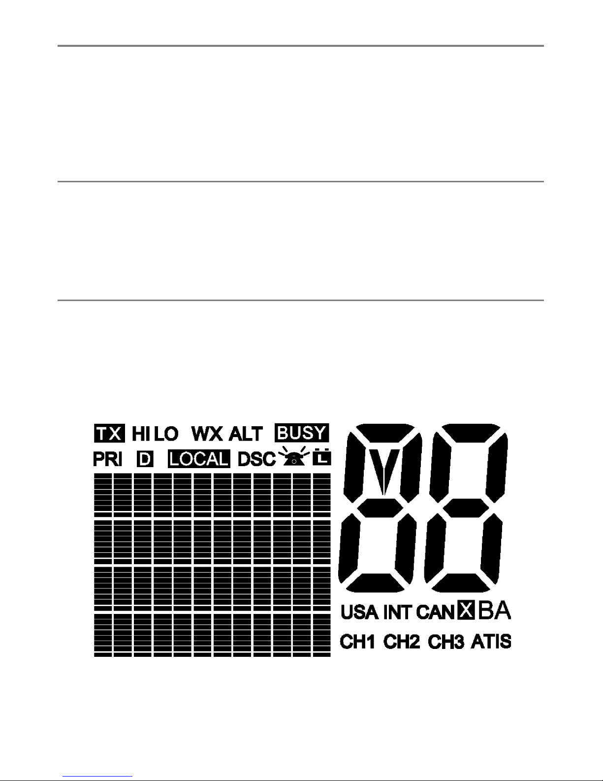
1-5 LCD Symbols and Meanings
This simulation shows the locations of all the following information symbols:
7Northtstar Explorer VHF Series: 710US, 710EU Operation and Installation Manual
Symbol Meaning
TX Transmitting.
HI LO Transmission power. High (HI) 25 W or Low (LO) 1 W.
WX Weather channel.
WX ALT Weather Alert. Alarm beeps will sound. VHF 710US only.
BUSY Receiver busy with an incoming signal.
PRI Priority channel is selected.
D Duplex operation. Otherwise, blank for Simplex operation.
LOCAL Local calling is selected. Otherwise, blank for distance calling.
DSC DSC capability is available. VHF 710US and VHF 710EU only.
Indicates an incoming DSC call, or blinks to notify you of any unread Call Log
messages
Low Battery warning (activates at 10.5 V)
88 Channel selected.
USA INT CAN Selected channel bank for VHF radio operations and regulations.
X Channel is temporarily deleted from the ALL SCAN operation.
B A Channel suffi x, if applicable.
CH1 CH2 CH3 Shows which of the 3 favourite channels, if any, are selected.
Otherwise blank.
ATIS Enabled for use in European inland waterways. Otherwise blank.
VHF 710EU only.
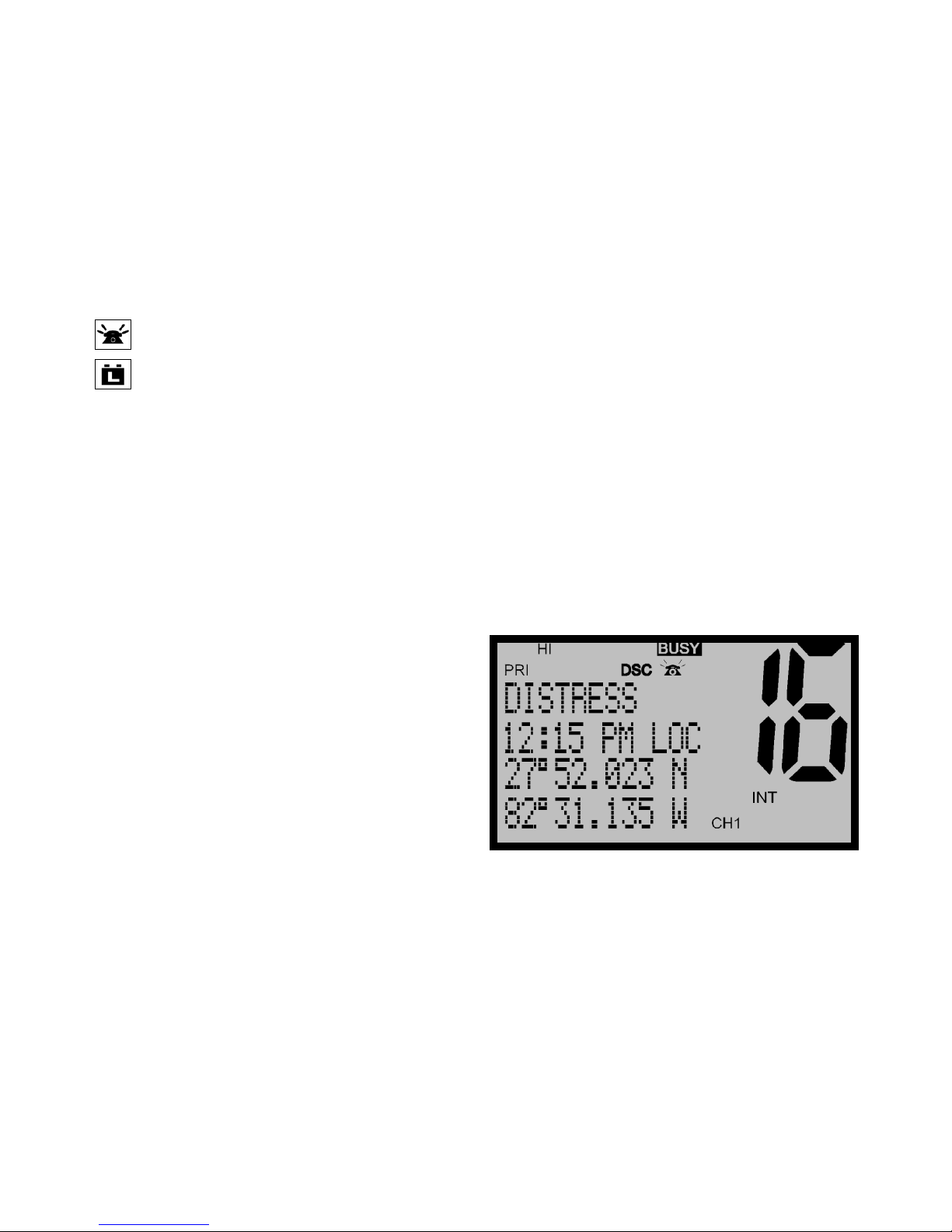
A typical operational display is shown here.
The latitude and longitude of the vessel and the local time are shown.
A transmission on Channel 16 is being made at high power using the International channel bank.
Channel 16 is set as the Priority channel. It is also set as favourite channel 1.
There is an incoming DSC call so the receiver is busy.
8 Northtstar Explorer VHF Series: 710US, 710EU Operation and Installation Manual
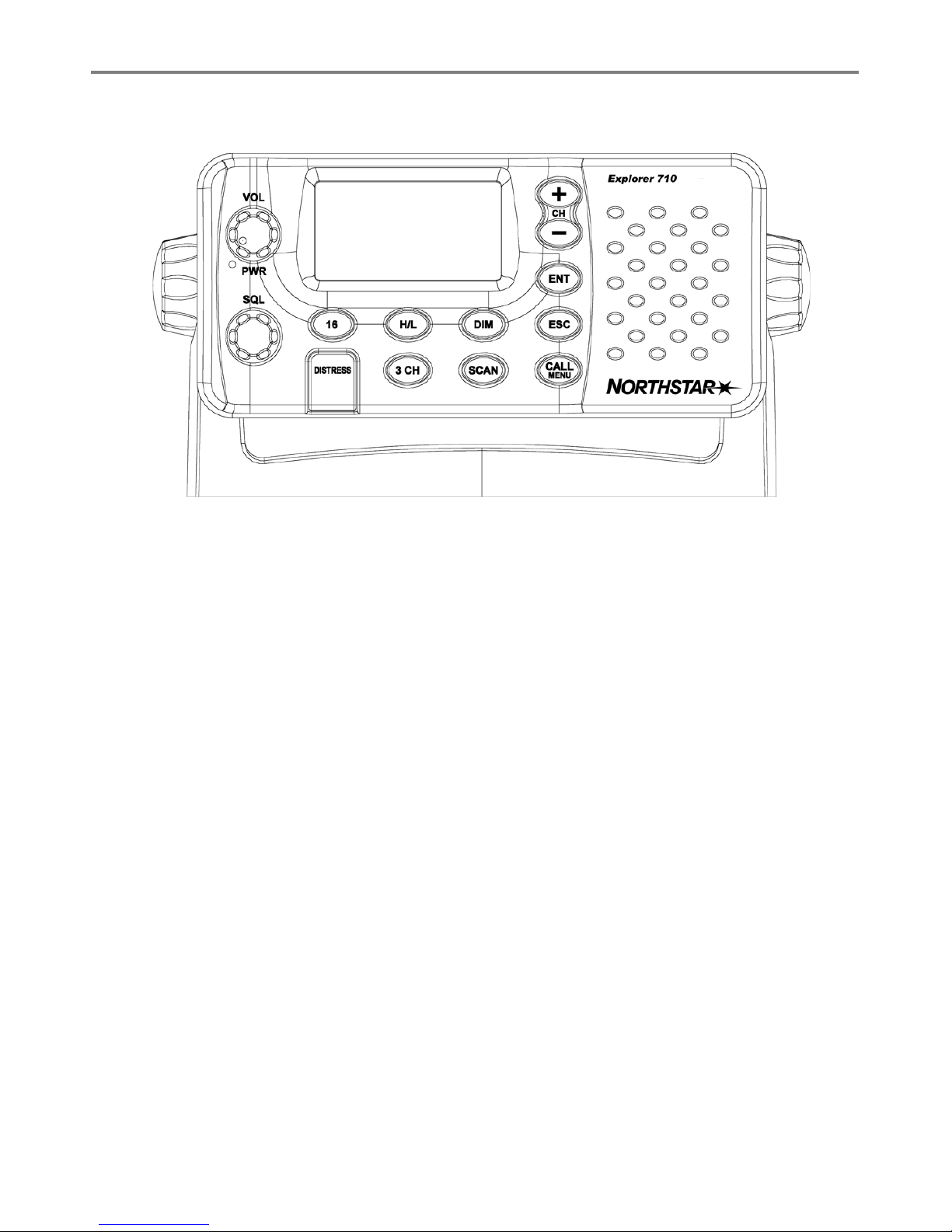
1-6 Basic Operation and Key Functions
All possible keys and their functions are listed. Note that some of the keys are not available depending on
your Northstar VHF radio model.
Key Function
VOL/PWR Volume and Power. Turn clockwise to power on. Continue to turn until a comfortable
volume is reached. VOL/PWR will also adjust the settings of an external speaker, if
connected.
SQL Squelch or Threshold Level. Sets the threshold level for the minimum receiver
signal. Turn fully counterclockwise until random noise is heard, then turn slowly
clockwise until the random noise disappears. Make another 1/4 turn clockwise for
best reception in open sea conditions.
In areas of high noise (eg close to large cities) reception may improve if sensitivity
is reduced. Either turn SQL slowly clockwise or use the LOCAL setting. See section
2.3.
16/9 Priority Channel. VHF 710US only. Also on the microphone. Press to cancel all other
modes and to tune into the priority channel. Press again to return to your original
channel.
The default is Channel 16. To make Channel 09 the priority channel, hold down 16/9
until a beep sounds and 09 is displayed.
16 Priority Channel. VHF 710EU. Also on the microphone. Press to cancel all other
modes and to tune into the priority channel, Channel 16, on high power. Press
again to return to your original channel.
WX Weather Channel. VHF 710US. In USA and Canadian waters, press to hear the most
recently selected weather station. The WX symbol is displayed on the LCD.
Press + or - to change to a diff erent weather channel. Press WX again to return to
the most recent channel.
If the weather alert mode (ALT) is ON and an alert tone of 1050Hz is broadcast from
the weather station, it is picked up automatically and the alarm sounds. Press any
key to hear the weather alert voice message.

9Northtstar Explorer VHF Series: 710US, 710EU Operation and Installation Manual
H/L Transmission Power. High (HI) 25 W or Low (LO) 1 W. Press to toggle between high
or low transmission power for the entire channel bank. The HI or LO selection is
shown on the LCD.
Some channels allow only low power transmissions. Error beeps will sound if the
power transmission setting is incorrect.
Some channels allow only low power transmissions initially, but can be changed
to high power by holding down H/L and PTT at the same time. See Appendix C for
a complete listing of channel charts.
3CH Three Favourite Channels. Also on the microphone. Press to toggle between your
favourite channels. The CH1, CH2, or CH3 symbol appears on the LCD to show which
favourite channel is selected.
To scan only one of your favourite channels, press 3CH then immediately press
and release SCAN. If you want to scan all three favourite channels, press 3CH then
immediately press and hold SCAN.
To add a favourite channel for the fi rst time, select that channel then hold 3CH
to store it in the CH1 location. Repeat the procedure to store two more favourite
channels in the CH2 and CH3 locations respectively.
If you try and add another favourite channel it will overwrite the existing CH3. CH1
and CH2 remain unless you delete them.
To delete a favourite channel, select that channel then hold down 3CH until the
CH1, CH2 or CH3 symbol disappears off the LCD.
UIC Channel Bank. 710US only. Press to toggle between USA, International or Canadian
channel banks. The selected channel bank is displayed on the LCD along with the
last used channel. All the channel charts are shown in Appendix C.
U/I Channel Bank. Press to toggle between channel banks. Note that the channel banks
available are dependent upon your VHF radio model. The selected channel bank is
displayed on the LCD along with the last used channel. All the channel charts are
shown in Appendix C.
DIM Backlighting. 710EU only. Press to toggle between the backlighting settings. OFF
will extinguish all the backlighting except for the DISTRESS key. (Otherwise, use the
menu to change the backlight setting.)
SCAN Scan. Press to scan between your current channel and the priority channel in DUAL
or TRI WATCH mode. The weather channel is also scanned if the USA channel bank
is selected and the weather alert mode (ALT) is ON.
Hold down SCAN to enter ALL SCAN mode where the priority channel is checked
every 1.5 seconds.
When a signal is received, scanning stops at that channel and BUSY appears on the
screen. If the signal ceases for more than 5 seconds, the scan restarts.
Press ENT to temporarily skip over (lock out) an “always busy” channel when in ALL
SCAN mode and resume the scan. An X is shown on the screen to designate a
skipped channel. Note that it is not possible to skip over the priority channel.
Press SCAN to stop at the current channel.
+ CH - Channel Select. Also on the microphone. The current channel is shown on the screen
in BIG digits with an appropriate designator suffi x A or B in small letters below the
channel number.

10 Northtstar Explorer VHF Series: 710US, 710EU Operation and Installation Manual
Press + or - to step through the available channels one at a time, or hold down
to scroll rapidly through all the available channels. See Appendix C for a listing of
channel charts.
Alphanumeric Entry. This key can also be used for menu selection and for alpha-
numeric entry. Press + or - to scroll the cursor up or down menu options when
navigating menus.
When editing an item containing only numbers, press - to count through the
numbers or hold down to scroll rapidly.
To enter a character, press + to step through the alphabet or hold down to scroll
rapidly.
ENT Enter. Use ENT when navigating menus, to confi rm entries and edits.
ESC Escape. Use ESC when navigating menus, to clear incorrect entries, to exit from a
menu without saving changes, and to back up to the previous screen.
CALL/MENU DSC Setup Menu and DSC Call Menu. 710US and 710EU only. Press to enter the DSC
Call Menu and make DSC calls. See Section 5.
Hold down to enter MENU SELECT. Scroll to DSC SETUP to setup your MMSID and
other DSC information. Go to RADIO SETUP to customize your Northstar VHF radio.
See Section 4.
MENU Radio menu. 7000 only. Press to enter the Radio Menu and customize your Northstar
VHF radio. See Section 3.
DISTRESS Send DSC Distress Call. 710US & 710EU only. See Section 6.
PTT Press To Talk. Press PTT to transmit at any time on an allowable channel. This auto-
matically exits you from menu mode and stops scanning. You must release PTT to
receive a signal.
If PTT sticks, a built-in timer will automatically shut down a transmission after fi ve
minutes and sound the error beeps.
This time out is required by FCC regulations.
Note: VHF 710CAN operation is the same as VHF 710US. Technical and DSC specifi cations for VHF
710CAN are the same as VHF 710EU

11Northtstar Explorer VHF Series: 710US, 710EU Operation and Installation Manual
UDDY LIS
T
LOCAL/DIS
T
ACKLIGH
T
NTRAS
T
PS/DATA
D
SC SETU
P
ADIO SET
UP
PS SIM
ESE
T
CH NAME
RING VOLUME
BEEP VOLUME
INT SPEAKER
WATCH MODE
WX ALERT
COM PORT
Maintain your buddy list.
See Section 2-2.
Set radio sensitivity.
See Section 2-3.
Set backlight level.
See Section 2-4.
Set contrast level.
See Section 2-4.
Set position & UTC manually.
See Section 2-5.
Set local time and time format.
See Section 2-5.
Radio Setup Menu.
See Section 3.
Turn the GPS Simulator on/off .
See Section 2.6.
Reset factory settings.
See Section 2.7.
Section 2 - The Radio Menu (MENU)
2-1 Radio Menu Options (Menu)
The following options are available through MENU (or CALL/MENU):
1-3 and 1-4 explain how to navigate around the menu and enter, save and change data.
MANUAL
SETTING
USER MMSID
GROUP SETUP
INDIV REPLY
DSC FUNC
ATIS MMSID
ATIS FUNC
LL REPLY
DSC Setup Menu.
710US and 710EU only.
See Section 4.
Make DSC calls.
710US and 710EU only.
See Section 5.

12 Northtstar Explorer VHF Series: 710US, 710EU Operation and Installation Manual
2-2 Maintain Your Buddy List (BUDDY LIST)
VHF 710US and VHF 710EU only.
Use the Buddy List to store the names and associated MMSIDs of 20 favourite people.
Names are stored in the order of entry, with the most recent entry shown fi rst.
The following sections show to use BUDDY LIST to add, edit, and delete entries on
your buddy list.
Section 3 explains how to call a buddy.
2-2-1 Add an Entry
1. Select BUDDY LIST. The cursor is at MANUAL NEW. Press ENT.
2. Enter the buddy name, one character at a time (this may be alphanumeric) then press ENT
repeatedly until the cursor moves to the MMSID entry line.
4. Enter the MMSID associated with that buddy name (this must be numeric) then press ENT.
5. The new buddy name and MMSID are displayed. Press ENT to store the new entry, which is displayed
at the top of your buddy list.
Note that when the BUDDY LIST is full (20 entries), you cannot make a new entry until you have deleted an
existing entry
.
2-2-2 Edit an Entry
1. Select BUDDY LIST. Press ENT to display the list of entries.
2. Scroll down (if required) to the incorrect entry and press ENT.
3. Select EDIT. The cursor is at the first character of the name.
4. Edit the buddy name or, to edit only the MMSID, press ENT repeatedly until the cursor moves to the
MMSID line.
5. When you are finished, press ENT (repeatedly if necessary) to display the next screen.
6. Press ENT to store the changes. The buddy list is displayed again. If more changes are required,
repeat Steps 2 thru 6. Otherwise, press ESC to exit.
MENU SELECT
>BUDDY LIST
LOCAL/DIST
BACKLIGHT
BUDDY LIST
> MANUAL NEW
ALEX
TOM
ENTER NAME
––––––––––––
ENTER MMSID
–––––––––
BOB
123456789
> STORE
CANCEL
ENTER NAME
BOB
ENTER MMSID
123456789
BUDDY LIST
> MANUAL NEW
ALEX
TOM
ALEX
> EDIT
DELETE
ALEX
111223344
> STORE
CANCEL
EDIT NAME
ALEX
EDIT MMSID
112233445
13Northtstar Explorer VHF Series: 710US, 710EU Operation and Installation Manual
2-2-3 Delete an Entry
1. Select BUDDY LIST. Press ENT to display the list of entries.
2. Scroll down (if required) to the entry you want to delete and press ENT.
3. Select DELETE then select YES.
4. The entry is deleted immediately and the buddy list is displayed again.
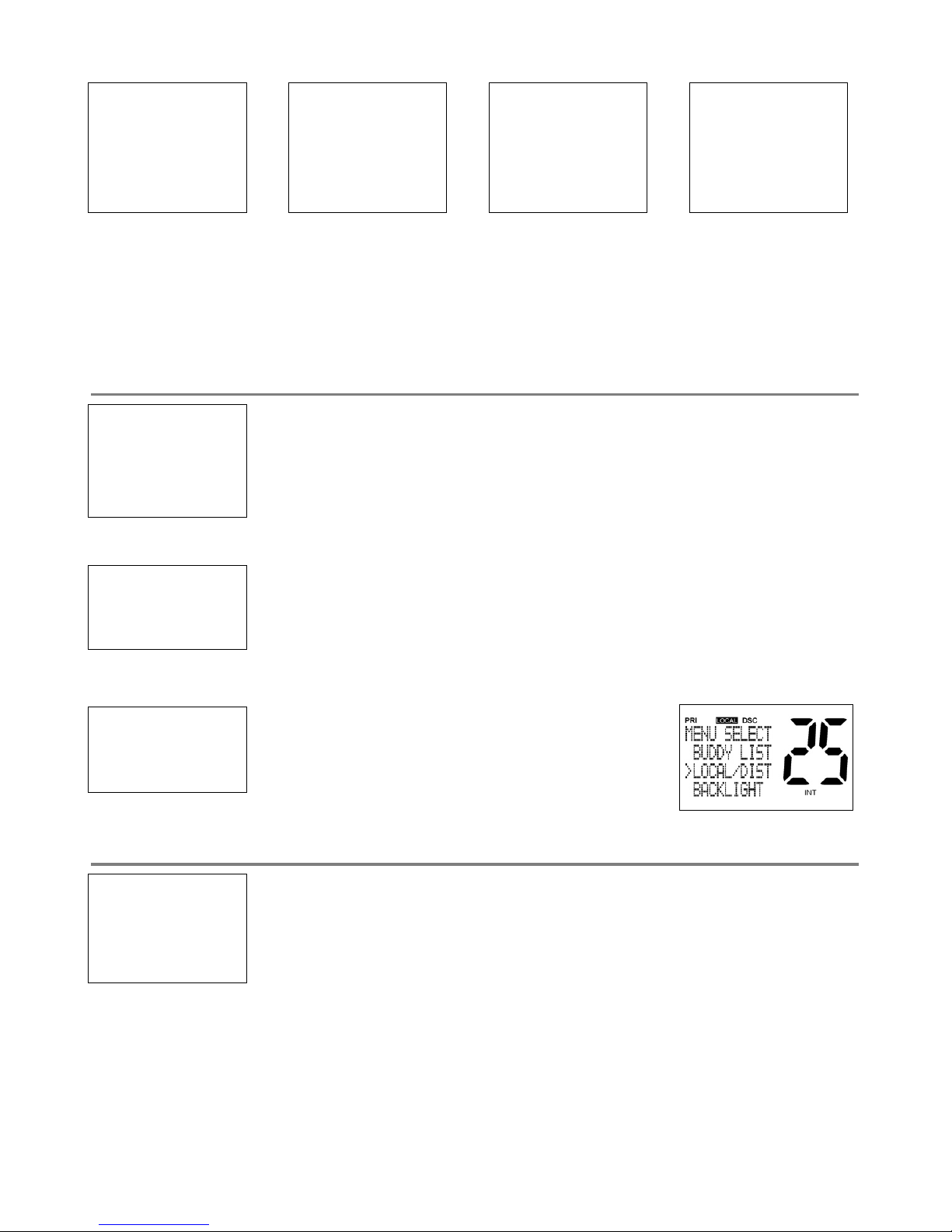
2-3 Local or Distance Sensitivity (LOCAL/DIST)
Use LOCAL/DIST to improve the sensitivity of the receiver either locally (LOCAL) or
over distances (DIST).
LOCAL is not recommended for use in open sea conditions. It is designed for use
in areas of high radio noise; for example, close to cities.
See also SQL (Squelch Control) in Section 1.6.
2-3-1 Set Distance Sensitivity
1. Select LOCAL/DIST then select DIST.
2. Press ENT to activate the DIST setting. This disables local sensitivity and the
menu is displayed again.
2-3-2 Set Local Sensitivity
1. Select LOCAL/DIST then scroll to LOCAL.
2. Press ENT to activate the LOCAL setting. This
disables distance sensitivity and the menu is
displayed again.
LOCAL is displayed on the LCD as a reminder that local sensitivity is selected.
2-4 Backlighting (BACKLIGHT) and Contrast (CONTRAST)
Use BACKLIGHT to set the backlight levels for the LCD and the keypad at a comfortable level.
The microphone keypad backlighting is either ON or OFF.
Use CONTRAST to set the contrast level for the LCD.
BUDDY LIST
> MANUAL NEW
ALEX
TOM
BUDDY LIST
MANUAL NEW
ALEX
> TOM
DELETE BUDDY
TOM
> YES
NO
TOM
EDIT
> DELETE
MENU SELECT
BUDDY LIST
> LOCAL/DIST
BACKLIGHT
SENSITIVITY
> DISTANT
LOCAL
SENSITIVITY
DISTANT
> LOCAL
MENU SELECT
LOCAL/DIST
> BACKLIGHT
CONTRAST
14 Northtstar Explorer VHF Series: 710US, 710EU Operation and Installation Manual
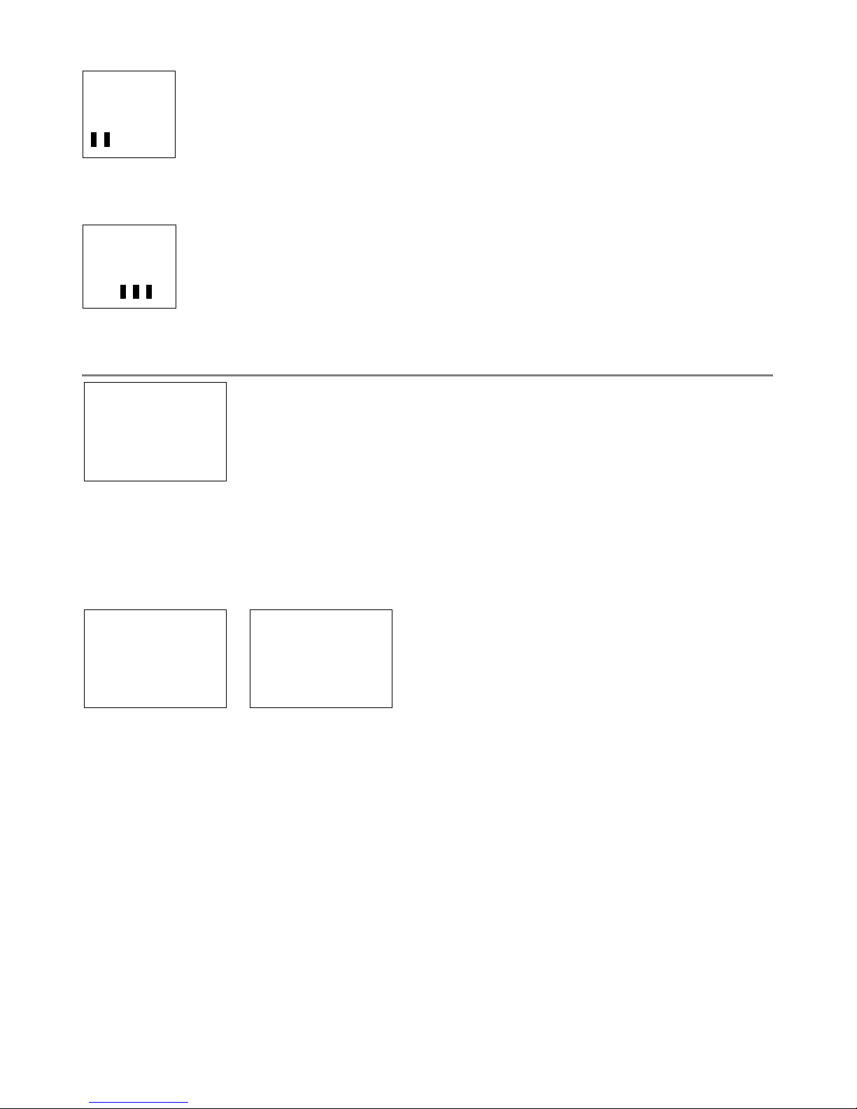
2-4-1 Set the Backlighting Level
1. Select BACKLIGHT.
2. Select a comfortable backlight level using + or - to change the setting.
3. Press ENT to enable the setting and return to the menu.
Note that the DISTRESS key backlighting cannot be switched off .
2.4.2 Set the Contrast Level
1. Select CONTRAST.
2. Select a comfortable contrast level using + or - to change the setting.
3. Press ENT to enable the setting and return to the menu.
2-5 GPS Data and Time (GPS/DATA)
If the boat has an operational GPS navigation receiver, the VHF radio automatically
detects and updates the vessel position and the local time.
However, if the GPS navigation receiver is disconnected or absent, you can specify
the vessel position and the local time manually, using the GPS/DATA option.
This information is important because it will be used if a DSC distress call is transmitted.
You can also enter the course (COG) and speed (SOG) and select GPS Alert and GPS Simulator options.
2-5-1 Manually Enter Position and UTC Time (MANUAL)
Note that this function is available only if an operational GPS receiver is not connected.
1. Select GPS/DATA, then MANUAL.
2. Enter the latitude, then the longitude, then the UTC.
3. Press ENT when all the information is correct.
The vessel’s latitude and longitude are shown on the screen, with the UTC time. The prefi x MAN indicates
a manual entry. The manual entries are cancelled if a real GPS position is received.
BACKLIGHT
LO HI
CONTRAST
LO HI
MENU SELECT
BACKLIGHT
CONTRAST
> GPS/DATA
GPS/DATA
> MANUAL
SETTING
MANUAL LL
––’ ––’ ––––N
––’ ––’ ––––W
MAN ––:––UTC
15Northtstar Explorer VHF Series: 710US, 710EU Operation and Installation Manual
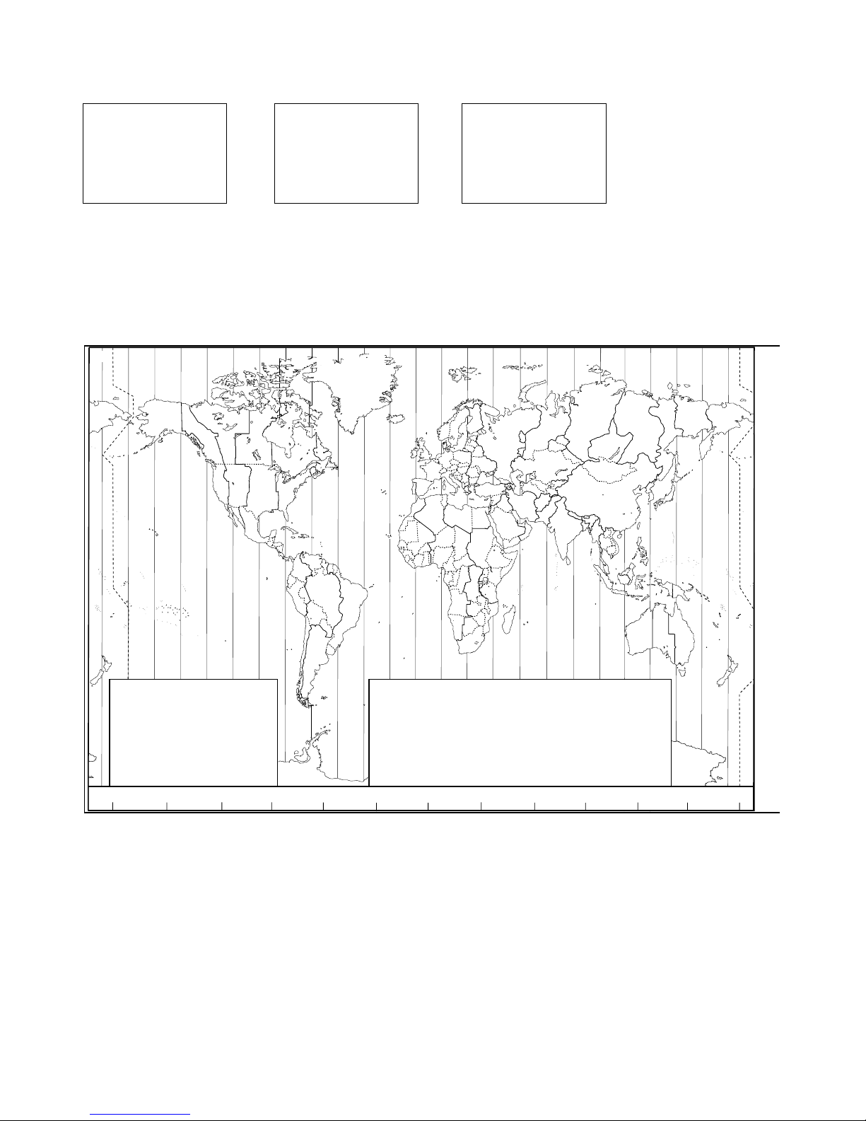
2-5-2 Local Time (TIME OFFSET)
The local time can be set by entering the time off set between UTC and local time as follows.
1. Select GPS/DATA, then SETTING.
2. Select TIME OFFSET to enter the diff erence between UTC and local time. Half hour increments can be
used with a maximum off set of ±13 hours.
In this example, a diff erence of +1.5 hours has been entered and the local time is displayed with the
suffi x LOC.
Z
A
B
C D F
G
H
I
N
O
P
Q
R
S
T
U
W
E
STANDARD TIME ZONES
Corrected to January 2005
Zone boundaries are approximate
Daylight Saving Time (Summer Time),
usually one hour in advance of Standard
Time, is kept in some places
Map outline © Mountain High Maps
Compiled by HM Nautical Almanac Office
Z
A
B
C
C*
D
D*
E
0
+1
+2
+3
+330
+4
+430
+5
E*
F
F*
G
H
I
I*
+530
+6
+630
+7
+8
+9
+930
K
K*
L
L*
M
M*
M†
+10
+10 30
+11
+11 30
+12
+13
+14
N
O
P
P*
Q
R
S
-1
-2
-3
-330
-4
-5
-6
T
U
U*
V
V*
W
X
Y
-7
-8
-830
-9
-930
-10
-11
-12
h
h
h
hh
m
m
m
m
m
No Standard Time legally adopted
‡
Standard Time = Universal Time + value from table
V
X
K
L
P
Q
Q
R
V
U
T
S
R
Q
P*
T
S
A
A
Z
B
C
Z
A
B
B
B
C
S
S
S
R
H
I*
K
K
M
M
‡
‡
H
H
H
I
K
E
F
G
E
D
*
*
*
*
C
C
D
F
G
H
D
E
F
H
I
G
C
D
D
E
K
L
M
Z
Z
P
N
0°
30°E
60°E
90°E
120°E
150°E
30°W
60°W
90°W
120°W
150°W
180°
180°
M
N
N
O
O
Z
Z
Z
C
D
D
E
F
E
*
E
*
F
*
K
L
*
*
L
L
M
M
Q
O
Q
A
S
U
W
V
*
A
Y
M
L
M Y
P
K
H
M
X
X
W
W
X
M*
W
M
*
M
*
M
M
L
F
M
Z
M
†
K
I
D
F
G
I
I
I
K
L
L
P
Z
International Date Line
International Date Line
WORLD MAP OF TIME ZONES
R
C
B
B
A
P
R
I
H
P
C
GPS/DATA
MANUAL
>SETTING
GPS/DATA
> TIME OFFSET
TIME FORMAT
TIME DISPLY
TIME OFFSET
>+01:30
02:30PM LOC

16 Northtstar Explorer VHF Series: 710US, 710EU Operation and Installation Manual
2-5-3 Time Format Options (TIME FORMAT)
Time can be shown in 12 or 24 hour format.
1. Select GPS/DATA, then SETTING.
2. Select TIME FORMAT.
3. Select 12 Hr or 24 Hr as desired. In this example, 12 hour format has been selected and so the LCD
shows the AM or PM suffix.
2-5-4 Time Display Options (TIME DISPLAY)
If you have entered the time manually as described in the previous sections, the time is always shown on
the screen with the prefi x M.
However, if the vessel position is being updated through a GPS navigation receiver, you can switch the time
display on the screen ON or OFF as follows:
1. Select GPS/DATA, then SETTING.
2. Select TIME DISPLAY.
3. Select ON (on) or OFF (off ) as desired. In this
example, OFF has been selected and so the
screen no longer shows the time.
If the time display is set ON, course and speed data are not displayed on the LCD (see
section 2-5-6).
2-5-5 Position Display Options (LL display)
If you have entered the vessel position manually as described in the previous section, the vessel position is
always shown on the screen with the suffi x M.
However, if the time is being updated through a GPS navigation receiver, you can switch the vessel position
display on the screen on or off as follows:
1. Select GPS/DATA, then SETTING.
2. Select LL DISPLAY.
3. Select ON (on) or OFF (off ) as desired. In this
example, OFF has been selected and the screen
no longer shows the vessel position.
2-5-6 Course & Speed Display Options (COG/SOG)
Use this option to display course over ground (COG) and speed over ground (SOG) data on the screen.
1. Select GPS/DATA, then SETTING.
2. Select COG/SOG.
3. Select ON (on) or OFF (off ) as desired. In this
example, ON has been selected and so the
screen shows the bearing and speed.
If GOG/SOG is set ON (on), the time is not displayed on the screen (see section 2-5-4).
GPS/DATA
TIME OFFSET
TIME FORMAT
> TIME DISPLY
TIME DISPLY
ON
> OFF
GPS/DATA
TIME FORMAT
TIME DISPLY
> LL DISPLAY
LL DISPLAY
ON
> OFF
GPS/DATA
TIME DISPLY
LL DISPLY
> COG/SOG
COG/SOG
> ON
OFF
GPS/DATA
MANUAL
> SETTING
SETTING
TIME OFFSET
> TIME FORMAT
TIME DISPLAY
TIME FORMAT
> 12 Hr
24 Hr
07:15AM LOC

17Northtstar Explorer VHF Series: 710US, 710EU Operation and Installation Manual
2-5-7 GPS Alert Options (ALERT)
The GPS alert is usually set to ON (on) so that if the GPS navigation receiver is disconnected, the alarm
sounds.
1. Select GPS/DATA, then SETTING.
2. Select GPS ALERT.
3. Select ON (on) or OFF (off ) as desired.
2-6 GPS Simulator (SIMULATOR)
The GPS Simulator is set to OFF whenever the radio is turned ON or whenever real GPS data is available
through the COM port. However, if you want to test it, turn it on.
1. Select GPS SIM, then select ON (on) or OFF (off ) as desired.
Whenever the GPS Simulator is turned ON (on), simulated Speed Over Ground
(SOG), Course Over Ground (COG), and LL position appear on the screen. This
data is updated automatically during the simulation.
It is not possible to send a DSC transmission when in Simulator mode.
2-7 Reset to Factory Defaults (RESET)
Use this to return every setting to the factory defaults except all MMSID settings and the entries in your
buddy list.
1. Select RESET. The radio asks for confirmation.
2. Select YES to reset the radio and return to the menu.
The Call Logs will be cleared but the BUDDY LIST will be saved. The receiver and transmitter factory
settings are restored to default conditions.
GPS/DATA
LL DISPLY
COG/SOG
> GPS ALERT
GPS ALERT
> ON
OFF
MENU SELECT
RADIO SETUP
GPS SIM
> RESET
RESET RADIO
ARE YOU SURE
> YES
NO
MENU SELECT
DSC SETUP
RADIO SETUP
> GPS SIM

18 Northtstar Explorer VHF Series: 710US, 710EU Operation and Installation Manual
Section 3 - Radio Setup Menu (RADIO SETUP)
3-1 Radio Setup Menu (RADIO SETUP)
Edit or delete channel names.
See Section 3-2.
Set the volume level of the incoming call notifi cation beeps.
See section 3-3.
Set the volume level of the beeps.
See section 3-3.
Switch ON/OFF (on/off ) the radio’s internal speakers.
See section 3-4.
Selects the operation of Dual or Tri watch scanning.
See section 3-5.
(Selects if the WX Alert scanning mode is ON (on) or OFF (off ). (VHF 710US only.)
See section 3-6.
Select NMEA protocol for communications between the VHF radio and any other
instruments.
See section 3-7.
Sections 1-3 and 1-4 explain how to navigate around the menu and enter, save and change data.
3-2 Channel Names (CH NAME)
The channel charts are listed in Appendix C with their default name tags. CH NAME gives you the option
to edit or delete the channel name tags displayed on the screen.
1. Select RADIO SETUP, then CH NAME.
2. Use + or - to step through the channels with their name tags until you see the channel name tag you
want to change, then press ENT. In this example, the channel name TELEPHONE associated with channel
01 is being changed to PHONE1.
3. Select EDIT and press ENT to edit the existing name tag. Input the new name
over the existing name.
It can be a maximum of 12 characters.
To delete the channel name, select DELETE and press ENT.
4. Press ENT (repeatedly if necessary) to display the YES/NO confi rmation.
5. Press ENT to confi rm the new channel name tag or the deletion, then press ESC to return to the menu.
CH NAME
RING VOLUME
BEEP VOLUME
INT SPEAKER
WATCH MODE
WX ALERT
COM PORT
RADIO SETUP
> CH NAME
RING VOLUME
BEEP VOLUME
EDIT CH NAME
TELEPHONE
CH NAME 01
TELEPHONE
SAVE CH NAME
PHONE1
> YES
NO
TELEPHONE
> EDIT
DELETE
 Loading...