


1
M459232C.3
ITEM NUMBER: 459232 & 459242
Owner’s Manual
Electric Stationary Air Compressor
(230V, single phase/80 gallon, 5 HP and 7.5 HP)
SERIAL NUMBER: _____________
Instructions for Installation/Set-up, Operation, Maintenance, & Storage
This NorthStar® belt-driven compressor has a 2-stage 3-cylinder pump (Model 459232) or a 2-stage 2-cylinder pump
(Model 459242), made with a heavy-duty cast iron cylinders for long life, and a compact design rated for 175
maximum PSI. Its continuous-duty rating ensures long-lasting performance, and its cast iron pump head ensures
superior heat dissipation.
Read and understand this Owner’s Manual completely before using. Keep this manual for future review. Failure to
properly set up, operate and maintain the compressor in accordance with this manual could result in serious injury or
death to operator or bystanders.
WARNING: SPECIAL HAZARDS
Injection Injury: High-pressure air stream can pierce skin and underlying tissues, leading to serious injury and possible
amputation. Such an injection injury can result in blood poisoning and/or severe tissue damage.
Flying Debris: High-pressure air stream can cause flying debris and possible surface damage.
Not For Breathing Air: NorthStar compressors are NOT designed, intended, or approved for supplying breathing air. No
compressed air should be used for breathing unless air is treated in accordance with applicable standards.
Fire/Explosion: Sparks from air powered tool heads or attachments can ignite fuel or other flammable liquids or vapors in
the vicinity. Exceeding the maximum pressure for air tools or attachments could cause them to explode.
Burns: Compressor pump, motor and discharge tubing are hot surfaces that can cause burn injuries.
Electric Shock: Operating equipment in wet conditions or where not properly grounded can cause electric shock.
Detailed safety information about these hazards appears throughout this manual.
Equipment Protection Quick Facts
Inspect Upon Delivery: FIRST! Inspect for missing or damaged components. See “Initial Set-Up” section for where
to report missing or damaged parts.
Check Pump Oil: Pump is shipped with oil. Check the pump oil level before starting. See “Preparing for Operation”
section of this Owner’s Manual for capacity and viscosity.
Use Mechanical Lifting Equipment: Compressor is shipped on a pallet and is too heavy to handle manually. Use
proper lifting equipment for unloading and moving to installation site.
Install Using a Qualified Electrician: All wiring, grounding, and electrical connections must be made by a qualified
electrician. Install according to local and national codes.
Install a Regulator: We recommend installing a regulator on the compressor at each distribution point to maintain
constant pressure in the outlet hose line and provide reduced pressure appropriate for air tool being used.
Run Pump Unloaded for Break-in Period: Before initial use, open ball valve and run compressor for 30 minutes to
break in pump parts.
Follow Maintenance Schedule: Pump, air filter, and tank require periodic inspection and servicing to provide
efficient function and long life. See “Maintenance Schedule” for frequency of servicing.

2
Table of Contents
Equipment Protection Quick Facts ........................................................................................................................................ 1
Table of Contents ........................................................................................................................................................ 2
About Your Air Compressor ....................................................................................................................................... 3
Specifications .............................................................................................................................................................. 4
Component Identification ........................................................................................................................................... 5
Safety Signal Words .................................................................................................................................................... 6
Safety Labeling ............................................................................................................................................................ 7
Initial Set-Up ................................................................................................................................................................ 9
Step 1. Inspect & Unpack ........................................................................................................................................................ 9
Step 2. Assembly ..................................................................................................................................................................... 9
Step 3. Select Suitable Location ........................................................................................................................................... 10
Step 4. Permanent Mounting ................................................................................................................................................ 10
Step 5. Installing Distribution Piping ................................................................................................................................... 11
Step 6. Wiring Installation ..................................................................................................................................................... 11
Operation ................................................................................................................................................................... 14
Follow Operation Safety Rules ............................................................................................................................................. 14
Prepare for Operation ............................................................................................................................................................ 14
Proper Air Hose and Tool Use .............................................................................................................................................. 15
Using Compressor for Spraying ........................................................................................................................................... 16
Shutdown ............................................................................................................................................................................... 16
Maintenance & Repair ............................................................................................................................................... 17
Maintenance Schedule Summary ............................................................................................................................. 17
Detailed Instructions – Maintenance & Repair ........................................................................................................ 17
Troubleshooting ........................................................................................................................................................ 20
Parts Explosions – Model 459232 & 459242 Rev C.3 .............................................................................................. 21
Parts List – Model 459232 & 459242 Rev C.3 .......................................................................................................... 22
459232 Pump Explosion ........................................................................................................................................... 23
459232 Pump Parts List ............................................................................................................................................ 24
459232 Pump Kits ...................................................................................................................................................... 25
459232 Pneumatic Schematic................................................................................................................................... 26
459242 Pump Explosion ........................................................................................................................................... 27
459242 Pump Parts List ............................................................................................................................................ 28
459242 Pump Kits ...................................................................................................................................................... 29
459242 Pneumatic Schematic................................................................................................................................... 30
Appendix A: Lubricants and Compatibility ............................................................................................................. 31
Alternate Lubricants ............................................................................................................................................................ 31
Limited Warranty ....................................................................................................................................................... 32

3
About Your Air Compressor
Thank you for purchasing a NorthStar air compressor! It
is designed for long life, dependability, and top
performance.
Intended Use. Provides compressed air used primarily
for operating air tools and pressurizing other objects
that require high air pressure, such as tires. Do not
use for low-pressure objects such as balloons, air
mattresses, and sport balls, which can explode
quickly and easily. Special precautions are
necessary when used for cleaning to prevent flying
debris hazards. It is not to be used to supply
breathing air.
Supplies Required. Normal operation will require you
to supply:
Pressure regulator (recommended)
Pump oil
Personal protection equipment
See “Specifications” section for more detail.
Site Location. Intended for indoor use.
Personal Protection. Wear safety apparel during
operation, including safety glasses with side and top
protection.
Adult Control Only. Only trained adults should set up
and operate the air compressor. Do not let children
operate.
Under The Influence. Never operate, or let anyone else
operate, the air compressor while fatigued or under
the influence of alcohol, drugs, or medication.
Keep this manual for reference and review.
ATTENTION: Rental Companies and Private
Owners who loan this equipment to others!
All persons to whom you rent/loan this air compressor
must have access to and read this Owner’s Manual.
Keep this manual with the air compressor at all times
and advise all persons who will operate the machine to
read it. You must also provide personal instruction on
how to safely set-up and operate the air compressor
and remain available to answer any questions a
renter/borrower might have. Owner’s Manuals are
available from NorthStar at 1-800-270-0810.
For any questions, comments, problems or part orders,
call Northern Tool at 1-800-221-0516.
4
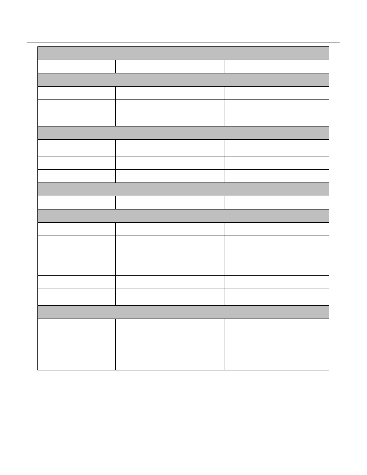
Specifications
MODEL
Model #
459232
459242
FLOW OUTPUT
Max. Pressure Rating
175 PSI
175 PSI
Volume Rating @ 90PSI
14.9 CFM
24.4 CFM
Receiver Capacity
80 gal.
80 gal.
Power Requirements
Dedicated NEMA
Receptacles
6-30R
6-50R
Volts
230V
230V
Amps
30A
40A
Motor
Horsepower
5 HP
7.5 HP
DIMENSIONS / COMPONENTS
Length
25”
25”
Width
33”
33”
Height
68”
69”
Weight
409 lbs.
537 lbs.
Mounting Hole Diameter
.56”
.56”
Suggested Mount Bolt
Diameter
7/16”
7/16”
SUPPLIES REQUIRED (not included)
Engine Oil
Refer to engine owner’s manual
Refer to engine owner’s manual
Pump Oil
(shipped with oil, but refills
required)
SAE 30 non-detergent pump oil
(#4043)
SAE 30 non-detergent pump oil
(#4043)
Pump Oil Capacity
27 oz.
33.8 oz.
5
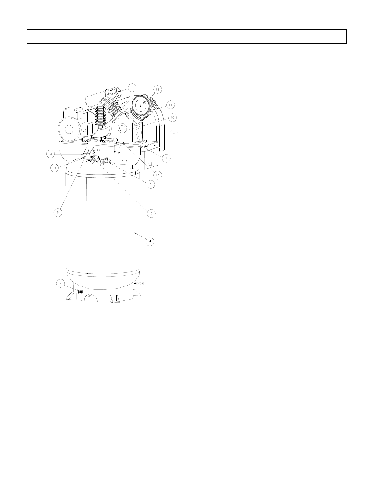
Component Identification
1. Lifting Eyes: May also be used as tie down locations.
2. Ball Valve: On/Off control for pressurized air supply
from receiver tank (not the output pressure). A
regulator and/or quick connect fittings can attach to
its ½” NPT outlet. A regulator should be installed
for pressure regulation purposes.
3. Pressure Gauge: Air filled gauge. Shows pressure in
receiver tank.
4. Air Receiver / Storage Tank: 80 gallon ASME certified
tank.
5. Discharge Tube: Carries compressed air from pump to
safety/check valve, and then to the storage tank. It
becomes very hot during use and can cause severe
burns. Never touch.
6. Pressure Switch-Auto/Off switch: In AUTO
position, compressor shuts off automatically when
tank pressure reaches maximum preset pressure
(approximately 175 PSI). In OFF position,
compressor will not operate. Switch should be in
OFF position when connecting or disconnecting
power cord from electrical outlet. NEVER attempt to
adjust this pressure switch.
7. Tank Drain Valve: Used to remove moisture from air
after compressor is shut off and air emptied from tank.
Drain moisture daily after each use.
8. ASME Safety/Check Valve: Automatically releases air if
tank exceeds preset pressure max. of 200 PSI. A check
valve is a pressure release port. Pull valve pin to relieve
pressure from receiver tank.
9. Unloader: Vents discharge air to atmosphere in
start/stop operation.
10. Air Compressor Pump: Shipped with oil.
11. Belt Guard: Covers belt, engine pulley and flywheel.
NEVER operate compressor without belt guard in place.
12. Compressor Air Filter: Keep clean and particle free.
See “Pump Explosion and Pump Parts List” for
replacement part number.
13. Magnetic Oil Drain Plug: Removal allows for drainage
of oil from pump. Attracts metal particles that could
damage pump.
14. Manual Tube. Storage for safety manual.

6
Safety Signal Words
DANGER
WARNING
CAUTION
CAUTION
NOTICE
Hazard Signal Word Definitions
This is the safety alert symbol. It is used to alert you to
potential personal injury hazards. Obey all safety
messages that follow this symbol to avoid possible injury
or death.
DANGER (red) indicates a hazardous situation, which if
not avoided, will result in death or serious injury.
WARNING (orange) indicates a hazardous situation,
which if not avoided, could result in death or serious
injury.
CAUTION (yellow), used with the safety alert symbol,
indicates a hazardous situation, which if not avoided,
could result in minor or moderate injury.
CAUTION (yellow), without the safety alert symbol, is
used to address practices not related to personal injury.
NOTICE is used to address practices not related to
personal injury.
7
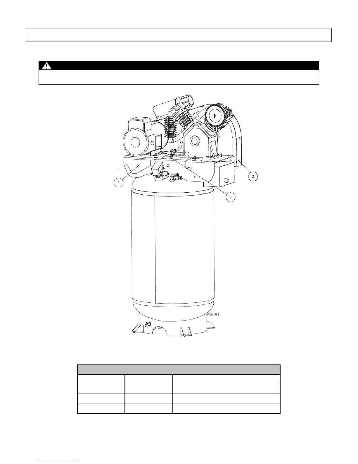
Safety Labeling
On-Product Warning Labels
Location
Part numbers
Description
1
788998
Air Compressor Instructions
2
788924
Air Compressor Safety
3
789060
Electrical Shock Hazard
Safety Decal Locations
WARNING:
ALWAYS make sure safety labels are in place and in good condition. If a safety label is missing or not legible, order new labels
from NorthStar Product Support at 1-800-270-0810.
8
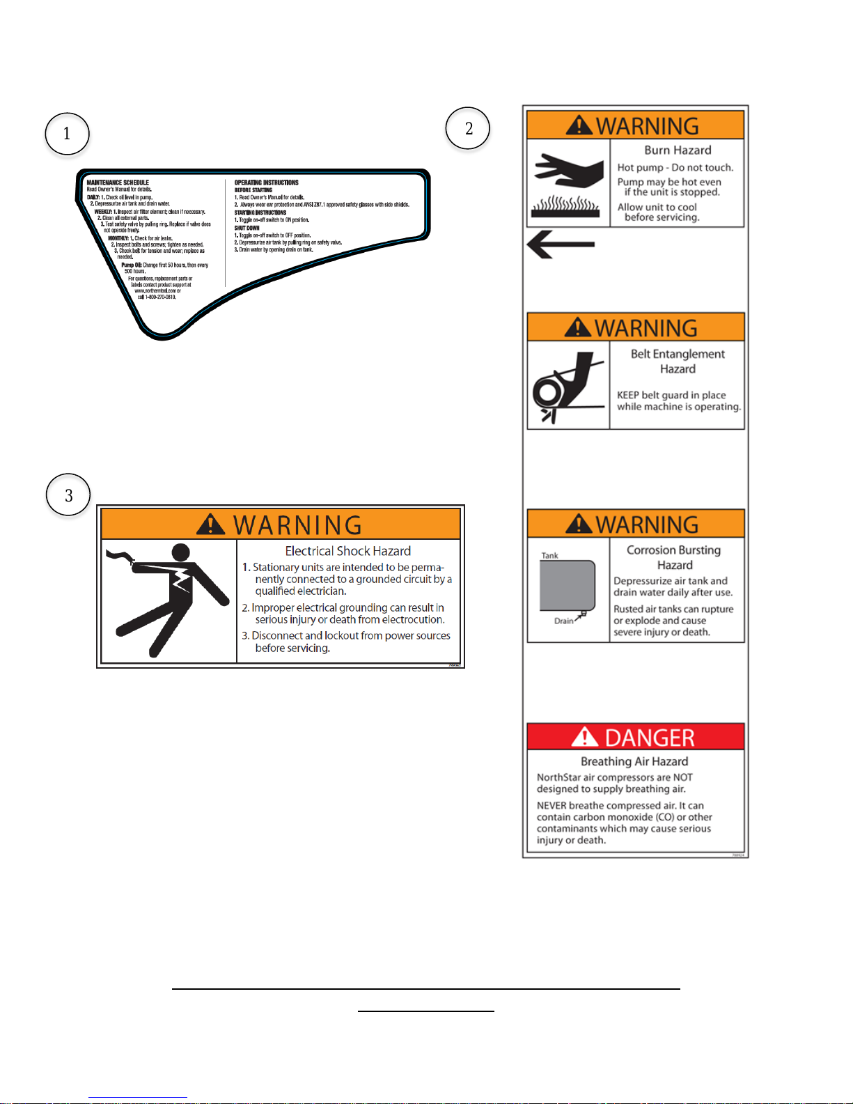
Safety Decals
1
2
3
To order replacement safety labels, call NorthStar Product Support
at 1-800-270-0810.

9
Initial Set-Up
Plastic plug
Base
Air Filter
Housing
Washer
Wing Nut
Grip here
to tighten
Step 1. Inspect & Unpack
Upon receipt, inspect air compressor for missing or
damaged parts. Verify that it is the compressor you
ordered.
See “Component Identification” section of this manual
for a diagram of the compressor and its components.
For missing components, contact Product
Support at 1-800-270-0810.
For damaged components, contact the freight
company that delivered the unit and file a claim.
If complete, fill out product serial number
information. See “Limited Warranty” section of
this manual.
Step 2. Assembly
Attach Air Filter (Model 459242 Only)
1. Remove air filter from manual bag.
2. Remove plastic plug from air compressor inlet.
(Figure 1)
Figure 3
Figure 4
5. Replace air filter housing and washer. Secure
with wing nut, hand tighten only. (Figure 5)
Figure 1
3. Unscrew wing nut, remove washer and air filter
housing from base. (Figure 2)
Figure 2
4. Screw base into air compressor inlet as shown.
Tighten with appropriate tool on specified
location. (Figure 3 & Figure 4)
Figure 5
Attach Regulator (Recommended)
We recommend using a regulator with this compressor
since the pre-set tank pressure ranges between 145 and
175 PSI and is usually greater than what is needed by
tools.
Without the addition of a regulator, the pressure switch
will maintain a tank pressure within the pre-set range
that has a max of 175 PSI. This is considered an overly
high pressure for many tools. A user-installed regulator
can maintain a lower constant pressure in the outlet
hose line and prevent over pressurization of tools.
WARNING: Bursting hazard
Too much air pressure causes a hazardous risk of
bursting. Check the manufacturer’s maximum pressure
rating for air tools and accessories. Regulators must
never be set to exceed the maximum pressure rating of
tank or tools.
10
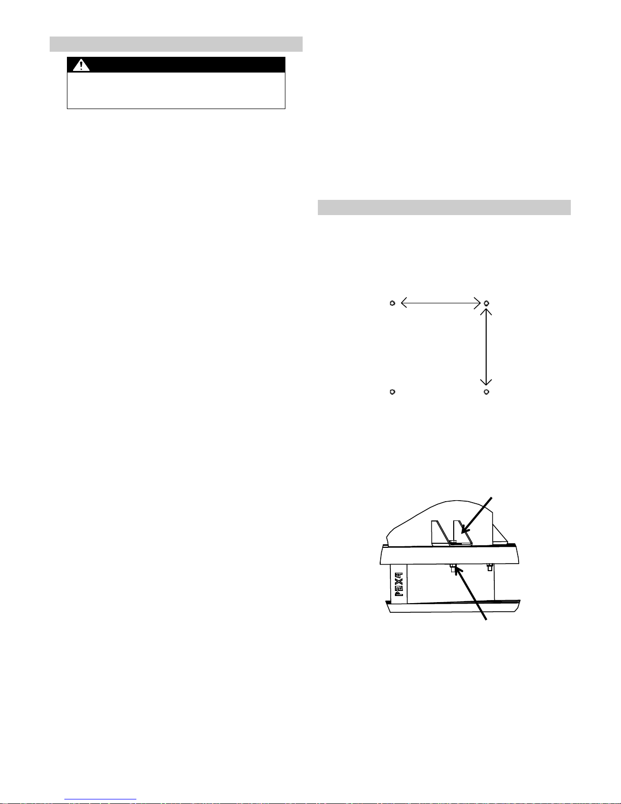
16.10”
16.10”
Nut
Step 3. Select Suitable Location
WARNING: Lifting hazard
The compressor is heavy. Ensure that proper lifting
equipment is available to unload and move compressor
to installation site.
Location Criteria:
Where no flammable vapors, dusts, and gases
are present.
At least 15” away from walls and other objects.
Away from other heat-generating equipment.
Away from dusty/dirty conditions.
In a well illuminated area.
Where proper wire size is already, or can be
made, available.
Positioning:
The compressor should be mounted on a dry,
firm, and level surface. It must sit level and be
stabilized since it will slide or shift during
operation if not secured.
Airflow:
Provide access to adequate, clean and
unobstructed airflow for cooling and air supply.
Remember the supply air is passing through the
compressor supply hoses and tools. These can
be damaged or have a shortened life if unclean
air is present or air filter is not clean and
functioning properly.
Do not allow debris to accumulate or block
airflow.
Do not operate with a tarp, blanket, or cover
surrounding the machine, which blocks air flow.
Do not place any objects against or on top of the
unit, which can also block airflow or damage unit.
Electrical:
MUST be connected to a 230 Volt, single-phase
outlet having operating capacity of 30 amp (Model
#459231, 5 H.P.) or 40 amp (Model #459241, 7.5
H.P.).
Wiring:
Proper wire size should take into consideration
length from distribution panel.
See Step 6, “Wiring Installation” for more
information.
Ideal operating temperatures:
40 and 100F (4 and 37C).
Operating Limitations:
15F (-9C) or above 125F (52C).
If temperatures consistently drop below 32 F (0C),
install within a heated building. If this is not possible,
protect the safety/relief and drain valves from freezing.
Note: Excessive moisture is likely to occur if unit is
stored in an unheated area subject to large
temperature changes. Moisture forming in pump can
produce sludge in the oil, causing parts to wear out
prematurely. Excessive condensation on the pump
when it cools down is a sign that this may be
occurring.
Step 4. Permanent Mounting
You will permanently mount the compressor after
selecting the location in Step 3.
1. On a concrete pad or other stable mounting
platform, drill 4 holes according to the mounting
dimensions given in the diagram below. (Figure 6)
Figure 6
2. Unbolt the compressor feet by removing the
bolts, washers and nuts. Discard them after
removal. (Figure 7)
Figure 7
3. Lift and remove the compressor from the pallet
using a hoist and lifting eyes provided.
4. Situate unit in chosen location and bolt in place.
(Use 7/16” bolts and washers. Make sure bolts
are long enough to provide a good anchor
point.) Bolt it in place to prevent unit from
11
vibrating excessively. Use metal shims under
the “short” feet if necessary.
5. A rubber isolation mat or pads may be used
under each mounting foot to reduce vibration.
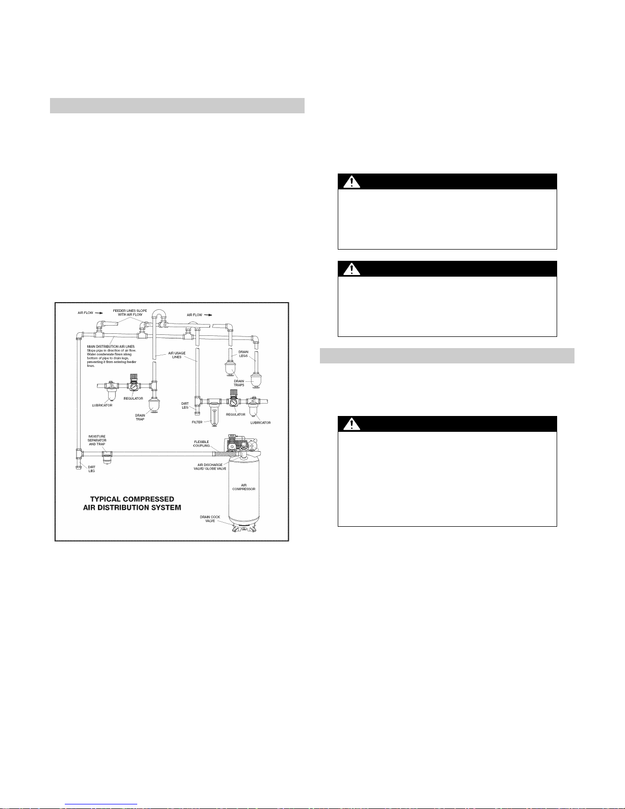
Step 5. Installing Distribution Piping
The stationary compressor can utilize the same type of
properly rated, single flexible hose, as is used on
portable air compressors. However, many purchasers
will prefer to utilize the stationary unit through a
permanently installed distribution system serving several
points within a facility. The design, installation and
usage of stationary compressed air distribution systems
has been the subject of extensive industrial, trade and
government attention, as can be seen within many
private and government websites.
An example of the typical components used in a
permanent distribution system are shown in Figure 8.
regulating the distribution line pressure at the
compressor outlet to under 150 PSI (usually in the 90120 PSI range) is mandatory for many compressed air
piping systems.
Northern Tool recommends that you contact plumbers
or mechanical contractors with expertise in compressed
air systems to plan and/or install your distribution
system.
WARNING: Bursting hazard
This unit can produce pressures in excess of 150 PSI,
which is beyond the capabilities of many piping types
and pipe fittings. Failure of undersized and/or
inadequate distribution components can lead to serious
injury.
WARNING: Restriction hazard
If an aftercooler, check valve, block valve, or any other
restriction is added to the compressor discharge, install
a properly sized ASME approved pressure safety/relief
valve between the compressor discharge and the
restriction.
Step 6. Wiring Installation
Wiring should be installed by a qualified electrician.
Installations must be in accordance with all applicable
local, state, and federal regulations.
WARNING: Electrical Shock Hazard
Improper electrical grounding can result in a risk of
electric shock. Electrical installation and service of the
230V, single-phase box (30 or 40 amp) MUST be made
by a qualified electrician. If the compressor must be
reinstalled at a different location, the re-connection
should also be made by qualified personnel. The
compressor motor may not start or may burn out
prematurely if adequate amperage is not available.
Figure 8
It should be obvious that there is considerable
complexity in designing and installing such a system.
Controlling the pressures, moisture in the air, drying
components, contaminants, lubrication, as well as
choosing and sizing the piping for the system, requires
the expertise of persons or firms familiar with such
designs and their installation.
A very significant safety issue arises when one is
distributing line pressure air throughout a facility, which
is over 150 PSI. Standard components, steel pipe
fittings and many plastic compressed air piping systems
are only rated to 150 PSI and cannot be safely used in
such distribution systems. In such cases, immediately
Electric Compatibility
The motor rating, as shown on the motor nameplate,
and the building power supply must have compatible
voltage, phase and hertz characteristics.
Wire Size
The electrical wiring required between the building’s
power supply and the electric motor varies according to
motor horsepower. Power leads must be adequately
sized to protect against excessive voltage drop during
start-up. High voltage drops can cause motor to
overheat and fail. A qualified electrician should provide
information for selecting proper wire size. If other
electrical equipment is connected to the same circuit,
the total electrical load must be considered in selecting
the proper wire size. DO NOT use undersized wire.
 Loading...