

Page 1
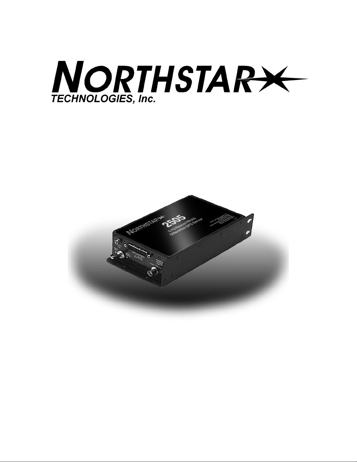
2505 Beacon/WAAS
Position Sensor
Installation Manual
Northstar Technologies
30 Sudbury Road
Acton, Massachusetts 01720
Revision A
Part Number GM2505
800/628-4487
978/897-6600
www.northstarcmc.com
Page 2

Page 3

Limited warranty policy
Northstar Technologies, Inc. warrants the Northstar 2505 to be free from defects in materials and
workmanship for a period of two (2) years. This warranty applies to the original purchaser and to any
subsequent owner during the warranty period, which begins on the date of shipment of the unit,
F.O.B. Acton, Massachusetts, to an authorized Northstar dealer.
Systems may not be returned to Northstar without a Returned Materials Authorization (RMA) number. Call the Northstar dealer or Northstar for instructions.
During the unit’s warranty period, Northstar will repair or replace, at its option, any part of the unit it
finds to be defective due to faulty material(s) or workmanship. All such repairs and/or replacements
will be promptly performed by Northstar free-of-charge to the owner, excluding freight costs
incurred in shipping to the factory. Return shipments from Northstar to points within the United
States are made via ground transportation, freight prepaid. Special shipping charges (overnight,
two-day, and so on) are the responsibility of the owner.
To be covered by this warranty, the Northstar equipment must have been in normal use. This warranty does not apply to units with defects caused by improper installation, physical damage, abuse,
tampering, lightning or other abnormal electrical discharge, or to units with defaced or altered serial
numbers, or to units repaired by unauthorized persons or repaired in a manner that violates Northstar’s recommended service procedures.
All repairs and/or replacements made under this warranty must be performed at Northstar’s facilities
in Acton, Massachusetts. Performance of warranty work elsewhere will not be authorized, and Northstar will not pay for any charges for such work. Northstar will not be responsible for payment of any
charges imposed by a Northstar dealer or other party for services requested by and/or performed for
a unit’s owner in connection with this warranty. Such services might include removal of the unit
from a vessel, inspection, packaging, handling, reinstallation, and the like.
Northstar Technologies, Inc. assumes no responsibility for any consequential losses of any nature
with respect to any of its products or services sold, rendered, or delivered. The foregoing is the only
warranty expressed or implied. No other warranty exists.
Page 4

Page 5

Table of Contents
List of Figures. . . . . . . . . . . . . . . . . . . . . . . . . . . . . . . . . . . . . . . . . . . . . . . . . . . . . . . . . . . . . . . . . . . . . . . . . . . . . . . . . . . . . . iii
List of Tables . . . . . . . . . . . . . . . . . . . . . . . . . . . . . . . . . . . . . . . . . . . . . . . . . . . . . . . . . . . . . . . . . . . . . . . . . . . . . . . . . . . . . . v
SECTION ONE Introducing the 2505. . . . . . . . . . . . . . . . . . . . . . . . . . . . . . . . . . . . . . . . . . . . . . . . . . . . . . . . . . . . . . . . .1
Who should read this manual . . . . . . . . . . . . . . . . . . . . . . . . . . . . . . . . . . . . . . . . . . . . . . . . . . . . . . . . . . 1
Scope of this manual . . . . . . . . . . . . . . . . . . . . . . . . . . . . . . . . . . . . . . . . . . . . . . . . . . . . . . . . . . . . . . . . . .1
Getting technical support . . . . . . . . . . . . . . . . . . . . . . . . . . . . . . . . . . . . . . . . . . . . . . . . . . . . . . . . . . . . . .2
Servicing the Northstar 2505 . . . . . . . . . . . . . . . . . . . . . . . . . . . . . . . . . . . . . . . . . . . . . . . . . . . . . . . . . . .3
Returning a 2505 for service . . . . . . . . . . . . . . . . . . . . . . . . . . . . . . . . . . . . . . . . . . . . . . . . . . . . . . . . . . .4
Introducing the 2505 . . . . . . . . . . . . . . . . . . . . . . . . . . . . . . . . . . . . . . . . . . . . . . . . . . . . . . . . . . . . . . . . .4
SECTION TWO Installing and interfacing the 2505 . . . . . . . . . . . . . . . . . . . . . . . . . . . . . . . . . . . . . . . . . . . . . . . . 11
Before installing the 2505. . . . . . . . . . . . . . . . . . . . . . . . . . . . . . . . . . . . . . . . . . . . . . . . . . . . . . . . . . . . .11
Installing the 2505 . . . . . . . . . . . . . . . . . . . . . . . . . . . . . . . . . . . . . . . . . . . . . . . . . . . . . . . . . . . . . . . . . . .13
Installing the AN205-P antenna . . . . . . . . . . . . . . . . . . . . . . . . . . . . . . . . . . . . . . . . . . . . . . . . . . . . . . .15
Interfacing the 2505 . . . . . . . . . . . . . . . . . . . . . . . . . . . . . . . . . . . . . . . . . . . . . . . . . . . . . . . . . . . . . . . . .17
Troubleshooting the installation. . . . . . . . . . . . . . . . . . . . . . . . . . . . . . . . . . . . . . . . . . . . . . . . . . . . . . .18
Appendix A Technical specifications . . . . . . . . . . . . . . . . . . . . . . . . . . . . . . . . . . . . . . . . . . . . . . . . . . . . . . . . . . . . . . 19
Appendix B Data characteristics . . . . . . . . . . . . . . . . . . . . . . . . . . . . . . . . . . . . . . . . . . . . . . . . . . . . . . . . . . . . . . . . . . 21
Input/output ports . . . . . . . . . . . . . . . . . . . . . . . . . . . . . . . . . . . . . . . . . . . . . . . . . . . . . . . . . . . . . . . . . . .21
Appendix C NMEA output protocol. . . . . . . . . . . . . . . . . . . . . . . . . . . . . . . . . . . . . . . . . . . . . . . . . . . . . . . . . . . . . . . . 23
GPS receiver’s NMEA message format . . . . . . . . . . . . . . . . . . . . . . . . . . . . . . . . . . . . . . . . . . . . . . . . . .23
Input sentences . . . . . . . . . . . . . . . . . . . . . . . . . . . . . . . . . . . . . . . . . . . . . . . . . . . . . . . . . . . . . . . . . . . . .26
Output sentences . . . . . . . . . . . . . . . . . . . . . . . . . . . . . . . . . . . . . . . . . . . . . . . . . . . . . . . . . . . . . . . . . . . .34
Glossary . . . . . . . . . . . . . . . . . . . . . . . . . . . . . . . . . . . . . . . . . . . . . . . . . . . . . . . . . . . . . . . . . . . . . . . . . . . . . . . . . . . . . . . . . . 49
2505 INSTALLATION MANUAL, Revision A Page i
Page 6

Page ii 2505 INSTALLATION MANUAL, Revision A
Page 7

List of Figures
Figure 1: 2505 case and mounting dimensions . . . . . . . . . . . . . . . . . . . . . . . . . . . . . . . . . . . . . . . . . . . . . 15
Figure 2: Northstar GPS/DGPS combo antenna . . . . . . . . . . . . . . . . . . . . . . . . . . . . . . . . . . . . . . . . . . . . . 16
2505 INSTALLATION MANUAL, Revision A Page iii
Page 8

Page iv 2505 INSTALLATION MANUAL, Revision A
Page 9

List of Tables
Table 1: Contacting Northstar . . . . . . . . . . . . . . . . . . . . . . . . . . . . . . . . . . . . . . . . . . . . . . . . . . . . . . . . . . . . . .4
Table 2: 2505 parts list . . . . . . . . . . . . . . . . . . . . . . . . . . . . . . . . . . . . . . . . . . . . . . . . . . . . . . . . . . . . . . . . . . .14
Table 3: Standard connector pinouts . . . . . . . . . . . . . . . . . . . . . . . . . . . . . . . . . . . . . . . . . . . . . . . . . . . . . . .17
Table 4: 2505 alternate connector pinouts . . . . . . . . . . . . . . . . . . . . . . . . . . . . . . . . . . . . . . . . . . . . . . . . . .18
Table 5: Sensor signals and I/O ports . . . . . . . . . . . . . . . . . . . . . . . . . . . . . . . . . . . . . . . . . . . . . . . . . . . . . . .23
Table 6: Standard configurations. . . . . . . . . . . . . . . . . . . . . . . . . . . . . . . . . . . . . . . . . . . . . . . . . . . . . . . . . . .24
Table 7: Connector pin assignments. . . . . . . . . . . . . . . . . . . . . . . . . . . . . . . . . . . . . . . . . . . . . . . . . . . . . . . .26
Table 8: NMEA field definitions. . . . . . . . . . . . . . . . . . . . . . . . . . . . . . . . . . . . . . . . . . . . . . . . . . . . . . . . . . . .31
Table 9: Primary port input messages . . . . . . . . . . . . . . . . . . . . . . . . . . . . . . . . . . . . . . . . . . . . . . . . . . . . . 32
Table 10: NVM elements . . . . . . . . . . . . . . . . . . . . . . . . . . . . . . . . . . . . . . . . . . . . . . . . . . . . . . . . . . . . . . . . .38
Table 11: Primary port output sentences . . . . . . . . . . . . . . . . . . . . . . . . . . . . . . . . . . . . . . . . . . . . . . . . . . .40
2505 INSTALLATION MANUAL, Revision A Page v
Page 10

Page vi 2505 INSTALLATION MANUAL, Revision A
Page 11

SECTION ONE Introducing the 2505
he Northstar 2505 Beacon/WAAS Position Sensor Installation
T
Manual describes how to properly mount, interface, and
troubleshoot the Northstar 2505 and Northstar AN205-P
combination GPS/beacon antenna.
Also described are the 2505’s configuration options, the
physical, mechanical, and electrical characteristics, and the
serial protocol used to communicate with a host device.
Who should read this manual
Scope of this manual
2505 INSTALLATION MANUAL, Revision A Page 1
This manual is intended for installation technicians who are
installing, connecting, and troubleshooting the 2505.
In this manual, you’ll find information about the following:
•
the 2505’s operating modes
•
mounting the 2505
•
interfacing the 2505 with a host device
•
installing the GPS/DGPS antenna
Page 12

SECTION ONE Introducing the 2505
•
troubleshooting
•
NMEA output protocol
Getting technical support
You can email the
Northstar Service
Department directly from
Northstar’s website,
www.northstarcmc.com.
Here, you also can access
additional technical
information under either
the Support
link (from this link you can
automatically open
manuals online using
Adobe’s Acrobat Reader.
or Manuals
After you’ve followed the instructions in this manual, if you
need additional technical or operations support, or if you have
any other service-related questions, please contact your dealer
or the Northstar Service Department. You can reach Northstar
by email, fax, U.S. mail, or phone as described in Table 1 below.
You can also visit Northstar’s website for additional
service-related information.
Please have the 2505’s serial number available and be as
complete and accurate as possible when describing the
problem. This ensures that a Northstar service technician can
research the issue and provide the quickest possible response.
Northstar’s Service Department is available between 9:00 AM
and 5:00 PM Eastern Time, Monday through Friday, excluding
major holidays.
If you’re looking for an authorized Northstar dealer, or product
information and brochures, contact the Northstar Sales
Department.
Table 1: Contacting Northstar
Email:
Service: [email protected]
Sales: [email protected]
Fax:
Service: 978/897-1595
Sales: 978/897-7241
Telephone:
Main number: 978/897-6600 or 800/628-4487
U.S. mail:
30 Sudbury Road
Acton, MA 01720
Website:
www.northstarcmc.com (you can send email to
Northstar directly from this site)
Page 2 2505 INSTALLATION MANUAL, Revision A
Page 13

SECTION ONE Introducing the 2505
Using the Dealer
Express web pages
Hearing from you
Ordering parts To order spare, replacement, or missing parts, call the Northstar
You can visit the Dealer Express area on Northstar’s website for
online service-related information (contact Northstar for a
dealer password before clicking on the Dealer Express
including the following:
•
service bulletins (for known issues and solutions)
•
software update information (for new software features)
•
service request form (for sending products back)
•
service status request form (for products currently under
repair)
•
warranty registration form (for registering new products)
Your feedback is important and helps Northstar ensure that this
manual is a valuable resource for all installation technicians.
Send your questions, comments, or suggestions about this
manual to:
Sales Department at 978/897-0770 or 800/628-4487.
link),
Servicing the Northstar 2505
The 2505 is repaired only by authorized Northstar dealers or
the Northstar factory. Service includes a complete hardware
and software check-out.
NOTE:
For a 2505 under warranty, shipping charges to the factory are
the only cost for factory repair. The repaired 2505 will be
returned via prepaid economy ground freight (freight for units
returned overseas is chargeable).
A 2505 and any accessories returned for warranty repair that
are determined to be without fault are subject to a handling
charge.
For 2505’s still under warranty, field repairs are not
authorized and will void the warranty!
2505 INSTALLATION MANUAL, Revision A Page 3
Page 14

SECTION ONE Introducing the 2505
Returning a 2505 for service
Before returning the 2505
to the Northstar factory, to
prevent delays it is critical
that you first obtain a
Return Materials
Authorization (RMA)
number from the Northstar
Service Department. If you
purchased the 2505
through a dealer, to get an
RMA number, call the
dealer with the 2505 serial
number, which is located
on the 2505’s label.
Shipments without a
proper RMA number will
not be accepted!
The 2505 is covered by a two-year hardware-only warranty,
which, in summary, states that if the 2505 is returned to the
Northstar factory by the owner or dealer during the warranty
period, Northstar will repair or replace, free of charge, any part
found to be defective due to faulty materials or workmanship if
the system has been properly installed and hasn’t been abused.
See the Limited Warranty Policy at the front of this manual for
further details. The only cost to the owner will be the one-way
shipping charges and any associated charges that may be
imposed by the dealer. If you have overnight or second-day
shipping requirements, before shipping the 2505, please call
Northstar for turnaround time, freight charges, and payment
arrangements.
The 2505 should be shipped only in a properly designed carton
with packing material. Shipments to the Northstar factory
should be made to the following address:
Northstar Technologies
Service Department
30 Sudbury Road
Acton, MA 01720 USA
Introducing the 2505
Page 4 2505 INSTALLATION MANUAL, Revision A
Northstar’s 2505 Beacon/WAAS Position Sensor comprises a
high-performance, fully automatic 12-channel GPS/WAAS
receiver, and a two-channel beacon receiver, packaged together
into a self-contained ruggedized enclosure. The 2505 provides
accurate GPS position data worldwide—in any weather, 24
hours a day—for such applications as soil sampling, yield
monitoring, field mapping, vehicle tracking, and so on. Position
measurements will be accurate to about 3 meters 95 percent of
the time, speed measurements to about 0.1 miles per hour, and
course-over-ground (COG) to about 0.5 degrees. In areas where
WAAS or beacon differential is available, accuracy will be better
than 2 meters.
The 2505 is easy to install and configure: Just connect the
external antenna and cables for your particular application, and
supply the power. The 2505 is fully automatic so you won’t
Page 15

SECTION ONE Introducing the 2505
need to see it, touch it, or send commands to it. By eliminating
virtually all of the attention needed to operate the 2505, you
can devote more time to other aspects of your work.
Understanding differential The 2505 receives differential WAAS corrections from
strategically located ground-based transmitters called beacons,
as well as from satellites transmitting WAAS differential signals.
The 2505’s advanced beacon/WAAS engine provides greater
accuracy than GPS alone.
Beacon differential
The Global Positioning System (GPS) uses a system of 24
satellites (with three spares) operating in three orbital planes at
about 11,000 miles elevation. Position is determined by
measuring the time delay of the 1575-mHz signal from at least
three of the satellites, and computing position based on known
satellite locations. Beacon differential signal corrections are
generated by ground-based reference stations, at precisely
surveyed locations, and transmitted to the end user via
minimal shift keyed 300-kHz U.S. Coast Guard beacons
(ground-based).
WAAS differential
As with the Coast Guard radiobeacons, the Wide Area
Augmentation System (WAAS) satellites use surveyed reference
stations to monitor GPS signals from each visible satellite and
determine if errors exist, and then develop corrections.
However, unlike Coast Guard radiobeacons or other land-based
transmitters on other frequencies, WAAS uses a network of
geostationary communication satellite transponders, in fixed
positions at approximately twice the distance from the earth’s
surface as the orbiting GPS satellites, on the same frequency as
GPS (1575 mHz). These satellite-based transmissions provide
consistent position corrections over a much greater contiguous
geographic location than the other radiobeacons. WAAS
differential corrections maintain a position accuracy of better
than 3 meters 2dRMS, without the signal interference problems
periodically experienced with low-frequency, shore-based
radiobeacon differential signals.
Standard 2505 features The 2505’s standard features include the following:
•
12-channel, high-performance GPS engine receiver with
integral two-channel WAAS differential reception and
position processing
2505 INSTALLATION MANUAL, Revision A Page 5
Page 16

SECTION ONE Introducing the 2505
•
2-channel, fully automatic beacon differential GPS
reception for accuracy better than 2 meters 95 percent of
the time
•
user-selectable (via switch) WAAS-only or WAAS with
beacon back-up
•
WAAS accuracy better than 2 meters 2dRMS 95 percent of
the time
•
fully automatic operating modes; no user intervention
required
•
NMEA GGA and VTG messages at 5-Hz data rate
•
internal beacon/GPS antenna splitter
For a complete list of the 2505’s technical specifications, see
“Appendix A Technical specifications” on page 19.
2505 operating modes The 2505’s GPS engine has seven operating modes:
•
Self-test
•
Initialization
•
Acquisition
•
Navigation (includes four sub-modes: Differential 3-D,
Differential 2-D, 3-D Nav, and Altitude-Hold)
•
WAAS/beacon differential
•
Dead-reckoning
•
Fault
The 2505 automatically switches between modes, and reports
the current operating and navigation modes through its host
port. The nine operating modes are described in detail below.
Self-test mode
The 2505 enters the self-test mode upon a host’s request, using
an NMEA message, via the GPS primary port, using either
RS-232 or RS-422. This test requires no more than 15 seconds.
When the self-test is completed, the 2505 reports the test
results on its host port through another NMEA message, and
then proceeds either to initialization mode if the test was
passed or to fault mode if a problem was detected.
Initialization mode
The 2505 automatically enters initialization mode when power
is applied or after completion of self-test mode. While in
initialization mode, the 2505 retrieves satellite orbital data
(ephemeris or almanac) stored in its EEPROM memory.
Integrity checking is performed on all data retrieved from the
Page 6 2505 INSTALLATION MANUAL, Revision A
Page 17

SECTION ONE Introducing the 2505
EEPROM to ensure accuracy. After initialization, the 2505
enters acquisition mode.
Acquisition mode
The 2505 enters acquisition mode whenever sufficient
real-time satellite data is available to produce an initial
navigation solution. Acquisition mode can be entered from
initialization, navigation or dead-reckoning mode. The 2505
exits either to navigation mode when satellites have been
acquired or to fault mode if a problem is detected.
After each satellite-in-view is acquired, the 2505 collects new
ephemeris data by decoding the satellite downlink data
message. When a sufficient number of satellites are being
tracked, then position, velocity and time are computed, and the
2505 enters navigation mode. If the 2505 can’t acquire signals
normally due to an absence of valid almanac data, it initiates a
“Search the Sky” acquisition, attempting to acquire any and all
satellites in the GPS constellation. After a satellite has been
acquired, ephemeris data is decoded from the satellite
down-link message. In “Search the Sky,” the Time-To-First-Fix
(TTFF) is typically less than two minutes. After a sufficient
number of satellites have been acquired, the 2505 enters
navigation mode. For TTFF details, see Table 4, “2505 technical
specifications,” on page 19.
Navigation mode
The 2505 operates in Navigation mode whenever sufficient
satellite information and measurement data are available to
produce a GPS fix. Navigation mode is entered from either
acquisition or dead-reckoning mode, and exits to
dead-reckoning or fault mode.
Navigation mode has three sub-modes: differential 3-D,
differential 2-D, and 3-D nav:
•
differential 3-D
•
differential 2-D
•
3-D nav
The 2505 automatically chooses the highest-performance
sub-mode available for the satellite data currently being
received, and reports to its host port the current navigation
sub-mode.
2505 INSTALLATION MANUAL, Revision A Page 7
Page 18

SECTION ONE Introducing the 2505
Differential 3-D
The 2505 operates in differential 3-D mode when it receives
data from at least four satellites with adequate geometry and
differential corrections, from either WAAS satellites or
radiobeacons. This is the navigation mode with the highest
performance.
Differential 2-D
The 2505 operates in differential 2-D mode when it receives
data from only three satellites with adequate geometry and
differential corrections, from either WAAS satellites or
radiobeacons. This is the navigation mode with the highest
performance when differential 3-D mode can’t be used.
3-D nav
The 2505 operates in 3-D nav mode when it receives data from
at least four satellites with adequate geometry, but no
differential corrections. This is the preferred navigation mode
when sufficient WAAS or radiobeacon corrections aren’t
available.
WAAS/beacon differential mode
While beacon and GPS acquisition is occurring, the 2505’s GPS
receiver is simultaneously searching for and acquiring the
WAAS differential signal from a geostationary satellite that
operates in the same frequency band as the GPS satellites. (To
avoid conflict, WAAS uses special PRN satellite identification
numbers.) Once the WAAS signal has been acquired and
settled, and provided that the GPS has entered navigation
mode, the 2505 can now enter WAAS or beacon differential
mode. WAAS and beacon modes are selected with a switch on
the connector panel. The switch functions are as follows:
•
In the “WAAS/beacon” position, WAAS will be used, but
will revert to beacon if WAAS is lost or unavailable.
•
In the “WAAS only” position, only WAAS differential
corrections will be used, if they’re available.
Dead-reckoning mode
The 2505 enters dead-reckoning mode when navigation mode
can’t be maintained. The speed and direction are assumed
constant, based on the last known data, to allow the 2505 to
provide an estimated position.
Page 8 2505 INSTALLATION MANUAL, Revision A
Page 19

SECTION ONE Introducing the 2505
Fault mode
The 2505 enters fault mode if it determines that its outputs are
affected by one or more critical system faults. This mode
supersedes all others and remains active until the next
power-down/power-up cycle. Fault mode can be entered from
any other mode, except initialization, whenever an
unrecoverable fault is detected. Fault mode protects against the
transmission of inaccurate data.
Automatic beacon
operation
The 2505 enters automatic beacon operations at power-up, and
requires no further supervision from the host GPS receiver.
Automatic operation is achieved by the use of two independent
receiver channels:
•
Channel 1 tracks the best available beacon signal (the one
with the lowest data error rate), and sends the
demodulated DGPS corrections to the GPS receiver.
•
Channel 2 continuously scans the entire beacon frequency
band (283.5 to 325 kHz) locating and measuring received
DGPS beacon signals. The 2505 then stores this
information as a DGPS beacon “directory” in
battery-powered memory.
If the signal received and monitored by Channel 1 degrades for
any reason, the 2505 selects a better frequency from its beacon
“memory.” This lets the 2505 switch to the best beacon signal
before your GPS accuracy is affected. Automatic beacon
operation can be used for all except the most specialized
applications, and is supported by most commercially available
GPS receivers.
At any time, the host device can override automatic station
selection by issuing NMEA tuning commands on the serial
interface. In this manual mode, the 2505 will output DGPS
corrections from the selected station. Automatic operation will
be restored at the next power-down/power-up cycle, or when
the host device issues a tune command frequency of “0” (zero).
For further details about manual mode, see “Appendix C NMEA
output protocol” on page 23.
2505 INSTALLATION MANUAL, Revision A Page 9
Page 20

SECTION ONE Introducing the 2505
Page 10 2505 INSTALLATION MANUAL, Revision A
Page 21

SECTION TWO Installing and interfacing the 2505
his section explains how to install the 2505, including
T
recommended mounting locations and methods, and how to
interface and troubleshoot.
Before installing the 2505
As shipped, the 2505 is ready to install and operate.
1. Check the shipping carton for any damage, and
immediately report any damage to the carrier. Save all
packing material in case you have to return the 2505 to
the factory for repair or evaluation.
2. Unpack the carton, and compare its contents with those
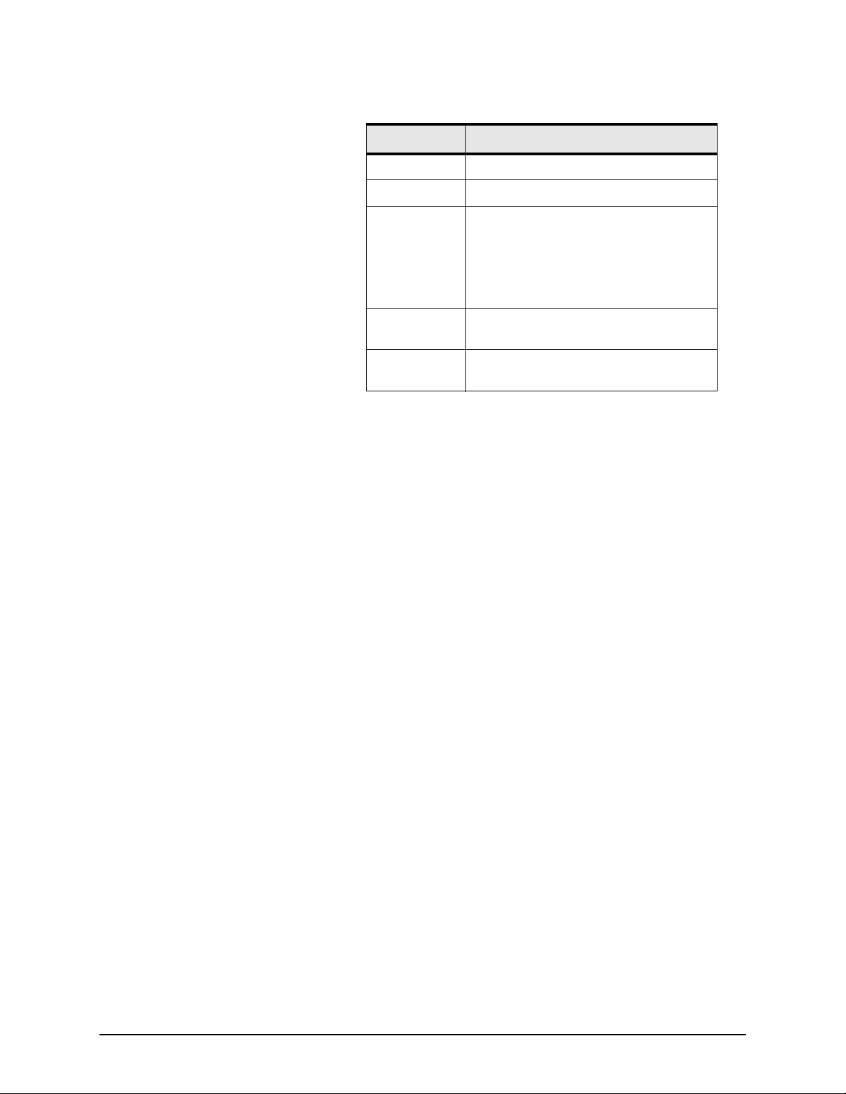
on the packing list and what you ordered. Table 2 on
page 12 lists the parts contained in the shipping carton.
2505 INSTALLATION MANUAL, Revision A Page 11
Page 22
SECTION TWO Installing and interfacing the 2505
Table 2: 2505 parts list
Part number Description
2505-A 2505 position sensor
2505-PK 2505 parts kit
AN205-P
WC-245
GM2505 Northstar 2505 Beacon/WAAS Position
8901-CA
(optional)
GPS/DGPS combination antenna
(standard with 2505)
GPS antenna connecting cable (RG-59/U
coaxial, 20 feet) with one TNC connector
and one BNC connector
Sensor Installation Manual, Rev. A
6-foot interfacing cable with DB9
termination
3. After inspecting the components, review all the
installation requirements, including:
•
the physical requirements (spacing, location with
regard to other equipment, etc.)
•
the electrical and electronic requirements
(interference between other pieces of equipment,
antennas, power requirements, etc.)
4. Preview/survey the desired layout and existing
equipment.
5. Select the desired mounting location; see ”Choosing the
2505’s mounting location” starting on page 13.
6. Install the 2505; see ”Mounting the 2505” starting on
page 13.
7. Install the antenna; see ”Installing the AN205-P antenna”
on page 15.
8. Wire the 2505 to power; for details, see ”Connecting the
2505 to power” starting on page 14.
9. Interface the 2505 to the desired device; see ”Interfacing
the 2505” on page 17. If you experience any operating
problems, see ”Troubleshooting the installation” on page
18.
Page 12 2505 INSTALLATION MANUAL, Revision A
Page 23
SECTION TWO Installing and interfacing the 2505
Installing the 2505
Choosing the 2505’s
mounting location
Mounting the 2505 You can mount the 2505 horizontally or vertically, using the
Although the 2505 is very straightforward and easy to
understand, you must meet several basic requirements to
ensure safe and proper operation.
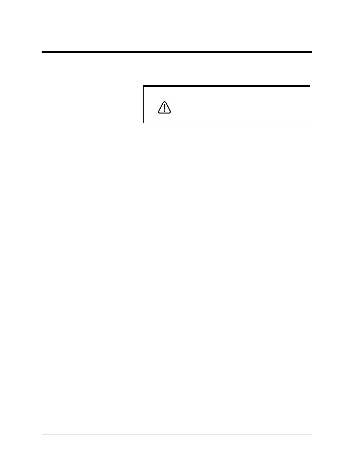
CAUTION!
The 2505 is housed in a rugged aluminum enclosure with a
mounting flange, gaskets, and watertight connectors. The 2505
itself is water-resistant, but not waterproof, so mount it where
water won’t contact it directly or enter it by following power or
antenna cables. Use drip loops on all cables! Tie-wrap all cables
to keep them secure, and if cables are shortened, lengthened,
or re-terminated, seal all wiring splices.
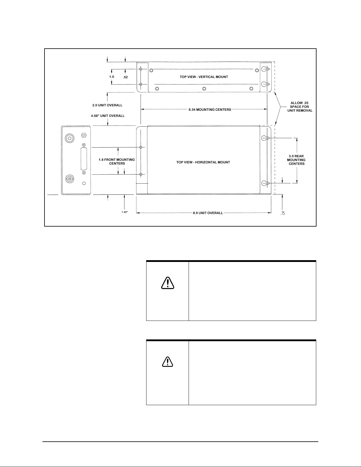
appropriate mounting holes; see Figure 1 on page 14. Keyhole
slots at the rear will help if you’re installing the 2505 where
access is limited and it may be difficult to start the mounting
screws at the obstructed end. Securely tighten all mounting
screws to avoid vibration-related problems.
Do not open the 2505. There are no serviceable
parts inside. Unauthorized tampering will
automatically void the warranty.
2505 INSTALLATION MANUAL, Revision A Page 13
Page 24
SECTION TWO Installing and interfacing the 2505
Connecting the 2505 to
power
Figure 1: 2505 case and mounting dimensions
WARNING!
CAUTION!
Be sure to ground the equipment to prevent
electrical shock and mutual interference.
Be sure that the power supply’s voltage is
compatible with the 2505’s voltage rating (10 to 40
volts DC). Connecting to the wrong power supply
can result in fire or damage to equipment.
Before applying power to the 2505, double-check
all the wiring. A small, but significant number of
units sustain damage due to incorrectly wired
connections. Such damage is not covered under
warranty. Be sure you don’t apply primary voltage
directly to any of the 2505’s signal input/output
wires as this may vaporize circuit board conductors
in the 2505.
Page 14 2505 INSTALLATION MANUAL, Revision A
Page 25

SECTION TWO Installing and interfacing the 2505
The 2505 requires 10 to 40 volts DC at approximately 10 watts.
The power supply is protected against reverse-polarity power
inputs. The 2505 has an internal ½-amp fuse.
The 2505 can be turned on remotely. If you connect pin 12 to a
switched source of +5 to +40 volts DC, the 2505 will turn on
whenever that voltage source is applied.
Power to the 2505 can be wired in either of two ways:
•
For permanent power-on in which there’s no remote-on
output available from the host device, connect pin 12 to
pin 25. As long as power is connected to pin 25, the 2505
will remain on.
•
For remote turn-on by the host device, connect pin 12 to
any host-switched +5V to +40 volts DC output of the GPS
host. In this configuration, the 2505 will turn on or off
whenever the host device is turned on or off.
Installing the AN205-P antenna
The 2505 operates exclusively with Northstar’s AN205-P
combination GPS/DGPS antenna. This “combo” antenna
provides an easier and more attractive installation than those
that use separate GPS and DGPS antennas. In many cases, the
loop antenna design also improves noise rejection of beacon
signals and provides better performance. For quick and easy
connection, the 2505 uses an internal antenna splitter to
separate the signal path of the one coaxial cable coming from
the AN205-P antenna.
2505 INSTALLATION MANUAL, Revision A Page 15
Page 26
SECTION TWO Installing and interfacing the 2505
7.00
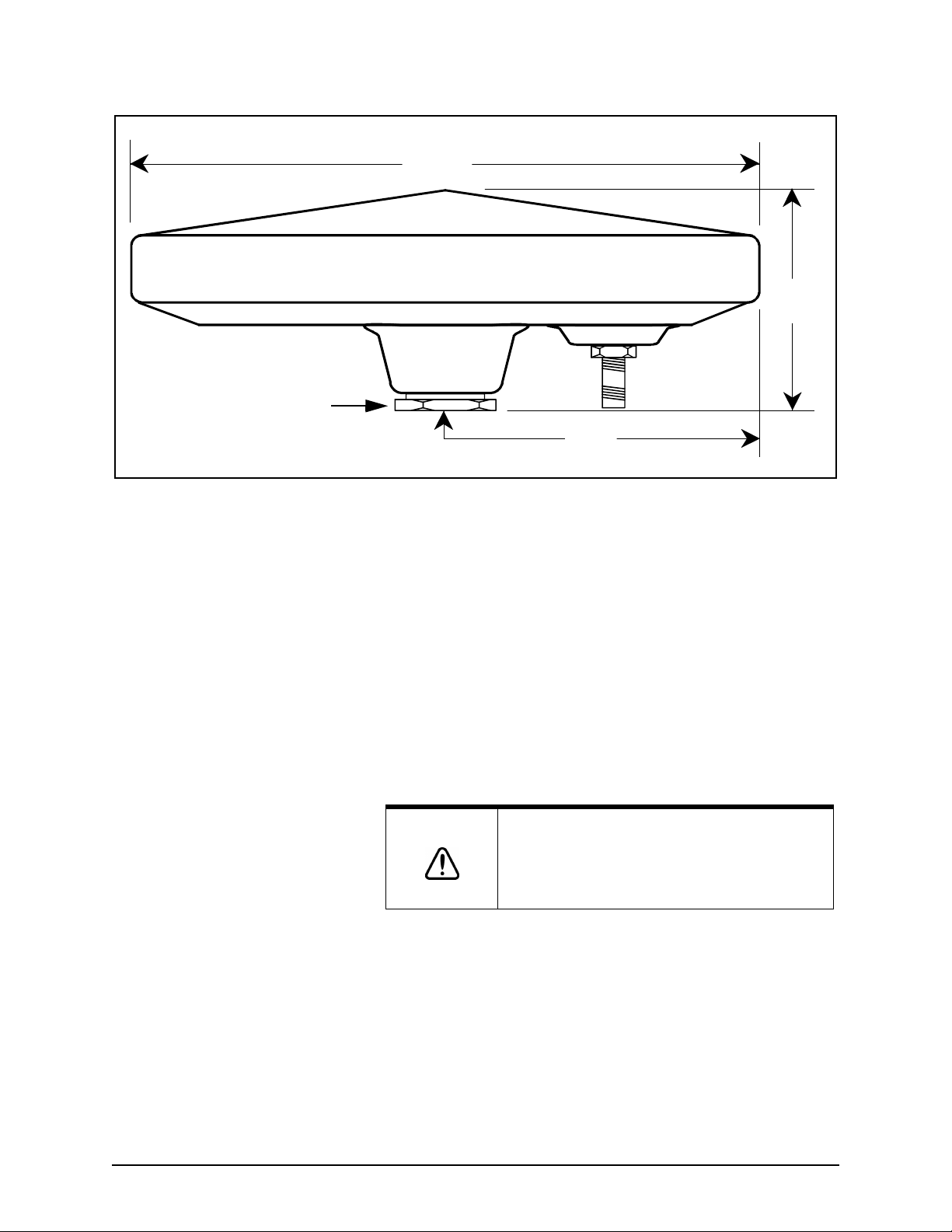
Use the locking nut shown to prevent
rotation of the antenna or bottoming
of the mounting stanchion into the
threaded mount portion of the
antenna. If done with enough force,
either of these may break the
antenna.
Figure 2: Northstar AN205-P antenna dimensions
2.5
TNC
3.5
Choosing the antenna’s
mounting location
Wiring the antenna
Mount the antenna near the top of the vehicle, where an
unobstructed view of the horizon is available in all directions,
but mount it lower than any high-power transmitting antennas,
such as radar or satcom.
Keep the antenna at least six feet away from objects that can
“shade” GPS or differential signals. If position data is
intermittent, check that you have the proper cable length, and
verify the quality of the antenna location and the quality and
proper termination of the connectors. Ensure that the 2505’s
ground lug terminal is securely connected to vehicle ground.
CAUTION!
When connecting the antenna to the 2505, you can use the
supplied coaxial cable or fabricate your own. In either case, the
cable length must be a maximum of 50 feet. (Using a cable
longer than 50 feet will require an antenna with a higher gain;
contact Northstar for details.) Don’t make any tight bends, and
fasten the cable along its length to avoid chafing or whipping of
any kind. Securely fasten all cable connectors.
Avoid mounting the antenna near rotating warning
beacons or strobe lights, electric motors, and
fluorescent lights. These can create RF
interference to the differential reception.
Page 16 2505 INSTALLATION MANUAL, Revision A
Page 27
Interfacing the 2505
SECTION TWO Installing and interfacing the 2505
Connecting the 2505 to
other equipment
The 2505 is easily interfaced to other equipment using the
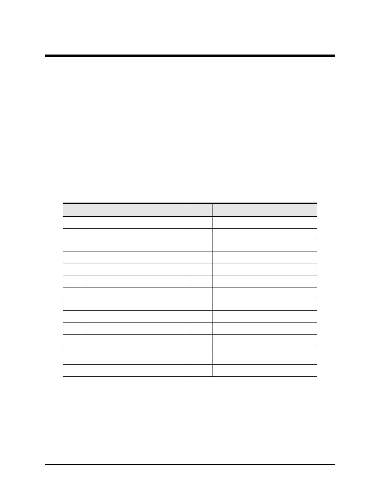
NMEA 0183 data format. Table 3 below lists the hardware port
numbers and the signal levels available on the connector pins
for a normal installation. Pins 6, 7, 8, 12, 13, and 25 (in bold
type) are the minimum connections required to operate the
2505. Choose either RS-422 or RS-232 pins as required by the
equipment to which you’re interfacing. For input/output
options, see “Appendix A Technical specifications” on page 19,
and for input/output protocols, see “Appendix C NMEA output
protocol” on page 23.
Table 3: Standard connector pinouts
Pin Description Pin Description
1 BDM control input A (RS-422) 14 BDM control input B (RS-422)
2 Ground 15 GPS primary input A (RS-422)
3 GPS primary input B (RS-422) 16 BDM RTCM SC-104 output A (RS-422)
4 BDM RTCM SC-104 output B (RS-422) 17 Ground
5 GPS primary output A (RS-422) 18 GPS primary output B (RS-422)
6 GPS primary output (RS-232) 19 Ground
7 GPS primary input (RS-232) 20 BDM RTCM SC-104 output (RS-232)
8Ground 21 BDM control input (RS-232)
9 BDM monitor output (RS-232) 22 Not Used
10 BDM monitor input (RS-232) 23 Configuration pin A (leave OPEN)
11 Configuration pin B (leave OPEN)
POWER ON
12
25 if no remote control)
13 (-) DC power input (ground) --- ---
a. Pins 11, 23, and 24 have been left open for future use.
2505 INSTALLATION MANUAL, Revision A Page 17
control (connect to pin
a
24 Configuration pin C (leave OPEN)
25 (+) DC power input
Page 28

SECTION TWO Installing and interfacing the 2505
Troubleshooting the installation
If you’re experiencing operating difficulties, perform the
following troubleshooting steps:
•
Verify the integrity of the coaxial connections at the 2505
and at the antenna.
•
To improve intermittent signal reception and performance,
look for loose connector crimps and unsecured cable
connections at the 2505 and at any equipment to which
the 2505 is interfaced. Tighten any connections.
•
Ensure that the 2505’s ground lug is connected to the
vehicle chassis ground.
Page 18 2505 INSTALLATION MANUAL, Revision A
Page 29
General characteristics
Appendix A Te c h n i c a l specifications
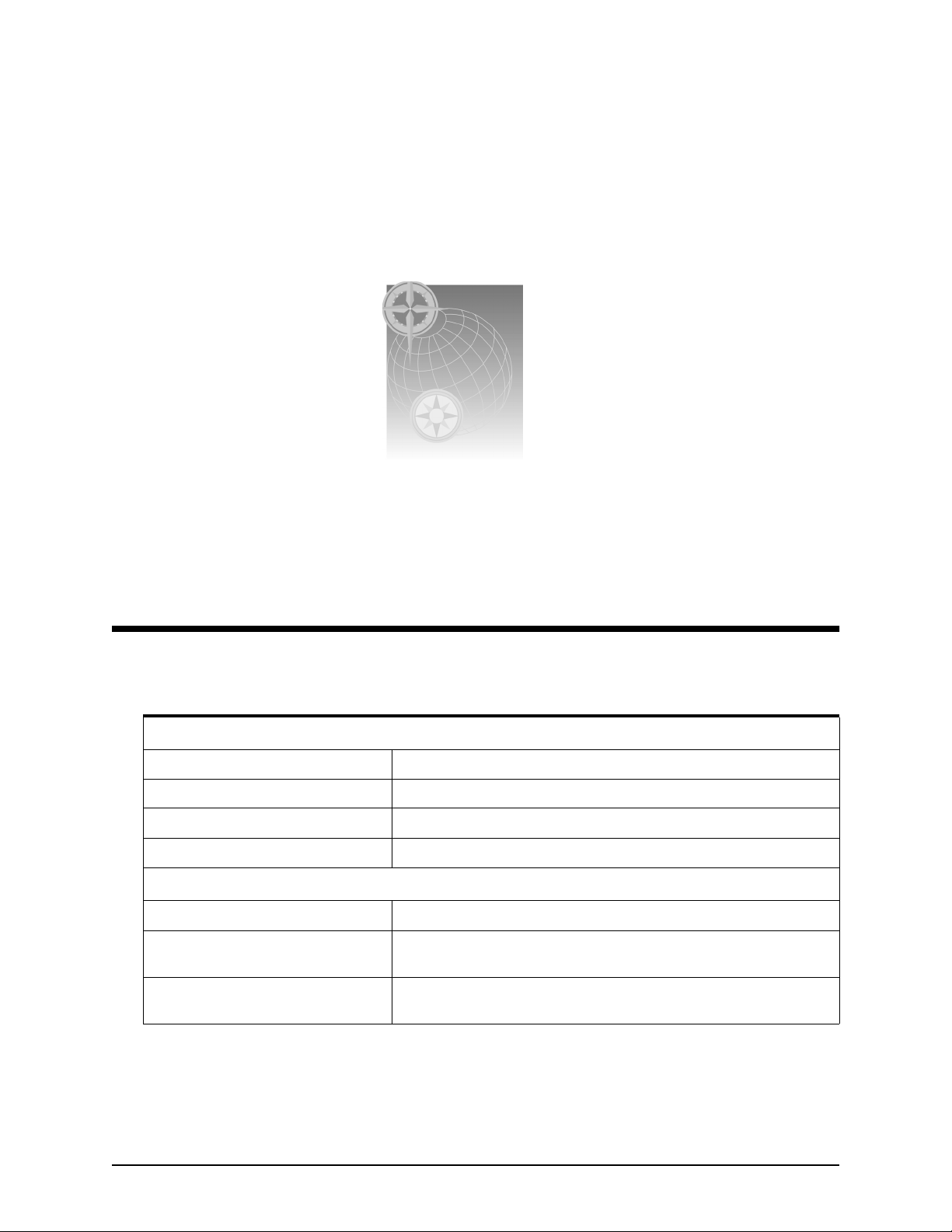
Table 4: 2505 technical specifications
L1 frequency 1,575.42 MHz
Coarse acquisition C/A code (1.023 MHz chip rate), code and carrier phase tracking
Sensitivity -135 dBm (antenna input level)
DGPS software Standard and enhanced with WAAS
Performance characteristics
Velocity 1852 km/h (514 m/sec) max
Acceleration 4 Gs (39.2 m/sec2)
Jerk: 2 m/sec
Position accuracy <1 m circular error probability (CEP), DGPS
<2 m circular error probability (CEP), WAAS
2505 INSTALLATION MANUAL, Revision A Page 19
3
Page 30
Appendix A Technical specifications
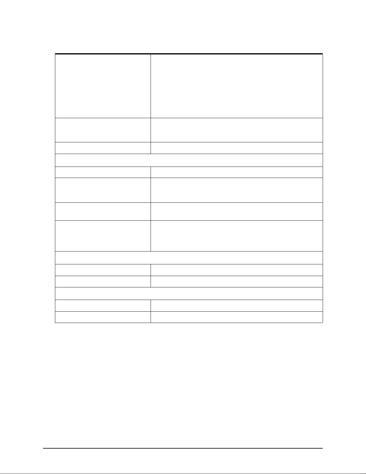
Table 4: 2505 technical specifications (continued)
Time-To-First-Fix (TTFF) Hot start: 20 seconds typical, with current almanac, position, time,
and ephemeris
Warm start: 45 seconds typical, with current almanac, position, time,
and ephemeris
Cold start: 2 minutes typical, no almanac, position, and time
With WAAS acquisition, add 30 seconds typical (max. 1 minute)
Re-acquisition time <1 second typical to re-acquire (5-second obscuration)
3 seconds typical to re-acquire (60-minute obscuration)
Channels allocation 10 GPS channels plus two WAAS satellites
Interface characteristics
Primary power 10 to 40 VDC (12V and 24V systems). 10 watts typical
Serial communications Three RS-232 and two RS-422 asynchronous data ports,
configurable from 300 to 38,400 baud for GPS outputs, 4800 and
9600 baud for SC-104 differential outputs.
Input messages NMEA 0182 protocol for GPS (for details, see “Appendix B Data
characteristics” on page 21). RTCM SC-104 for beacon differential.
Output messages NMEA 0182 GGA and VTG at 5-Hz update rate standard on GPS
output port; other NMEA outputs available (for details, see “Appendix
B Data characteristics” on page 21). RTCM SC-104 on beacon output
port.
Physical characteristics
Dimensions 2.0” high x 4.68” wide x 8.9” deep
Weight 2 pounds
Environmental characteristics
Operating temperature Receiver: 0°C to +50°C. Antenna/preamp: -40°C to +50°C
Humidity Receiver: 100%. Antenna/preamp: 100%
Page 20 2505 INSTALLATION MANUAL, Revision A
Page 31

Appendix B Data characteristics
Input/output ports
The 2505 contains a GPS receiver and a beacon receiver. Each
2505 has two full-duplex serial ports that may be
interconnected with each other, and with external devices in a
variety of ways for different applications.
Both RS-422 and RS-232 inputs and outputs are provided and
have separate pins on the I/O connector. RS-422 and RS-232
outputs may be used simultaneously; however, in general, only
one of the two receiver inputs for a particular port should be
connected.
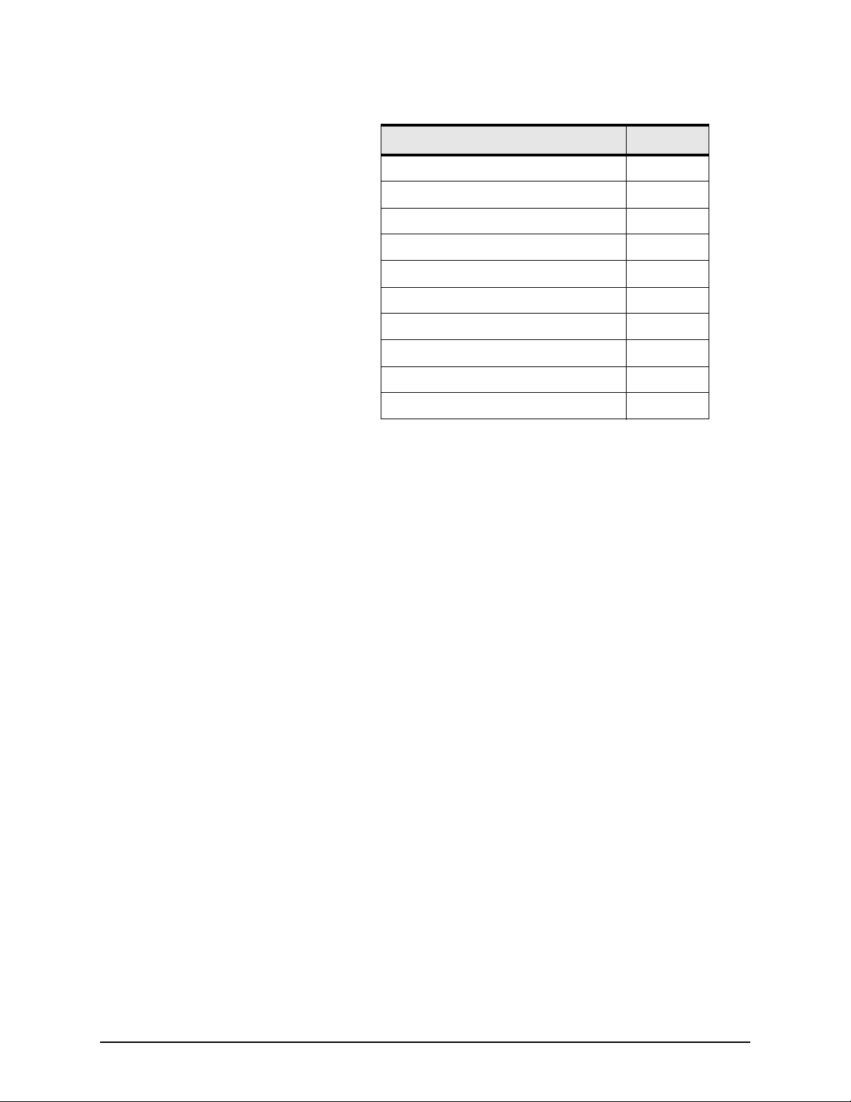
The available 2505 signals and I/O ports are shown in Table 5
on page 22.
2505 INSTALLATION MANUAL, Revision A Page 21
Page 32
Appendix B Data characteristics
Table 5: 2505 signals and I/O ports
I/O ports Pin
RS-232 receiver 1 input 7
RS-232 receiver 2 input 21
RS-232 receiver 3 input (optional) 10
RS-422 receiver 1 input (A/B) 15, 3
RS-422 receiver 2 input (A/B) 1, 14
RS-232 transmitter 1 output 6
RS-232 transmitter 2 output 20
RS-232 transmitter 3 output (optional) 9
RS-422 transmitter 1 output (A/B) 5, 18
RS-422 transmitter 2 output (A/B) 16, 4
Page 22 2505 INSTALLATION MANUAL, Revision A
Page 33
Appendix C NMEA output protocol
his appendix includes information about the NMEA message
T
format for the GPS receiver, as well as input and output
sentences.
GPS receiver’s
NMEA message
This section describes the serial protocol used by the GPS
receiver to communicate with a host device. The serial
communication runs under the following set-up:
format
Speed: 300 to 38,400 baud (default is 4800 baud
Format: 8-bit data, 1 start bit, 1 stop bit, no parity
(10 bits/character)
Data on the serial port is transmitted in one or more
NMEA-approved or proprietary sentences that have the
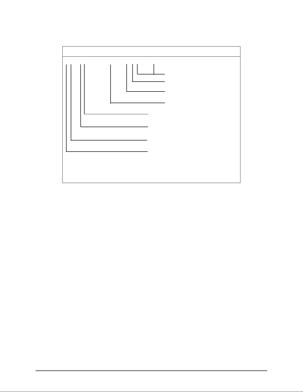
following structure.
2505 INSTALLATION MANUAL, Revision A Page 23
Page 34
Appendix C NMEA output protocol
HEADER CONTENTS OF DATA FIELDS
$PMCAG,xxx,xxx,xx,xx,...*CK<CR><LF>
end of sentence
checksum
checksum field delimiter
data (1st field = message
identifier
interface ID
(G = GPS)
originator ID
(MCA = Canadian Marconi Company)
Special ID
P = Proprietary
Record sync character
The types of fields are defined in Table 6 on page 25.
Page 24 2505 INSTALLATION MANUAL, Revision A
Page 35
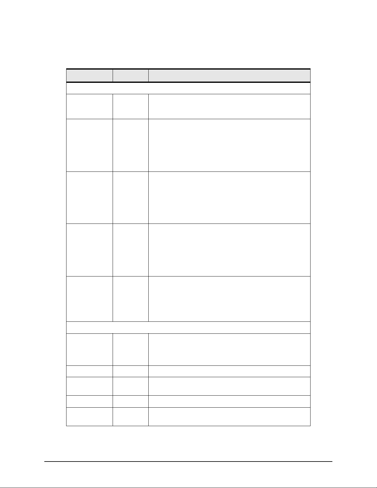
Table 6: NMEA field definitions
Field type Symbol Definition
Special format fields
Status A Single character field:
A = Yes, Data Valid, Warning Flag Clear
V = No, Data Invalid, Warning Flag Set
Latitude llll.ll Fixed/Variable length field:
Degrees/minutes.decimal - 2 fixed digits of degrees, 2 fixed
digits of minutes and a variable number of digits for
decimal-fraction of minutes. Leading zeros always included for
degrees and minutes to maintain fixed length. The decimal
point and associated decimal-fraction are optional if full
resolution is not required.
Longitude yyyyy.yy Fixed/Variable length field:
Degrees/minutes.decimal - 3 fixed digits of degrees, 2 fixed
digits of minutes and a variable number of digits for
decimal-fraction of minutes. Leading zeros always included for
degrees and minutes to maintain fixed length. The decimal
point and associated decimal- fraction are optional if full
resolution is not required.
Appendix C NMEA output protocol
Time hhmmss.ss Fixed/Variable length field:
hours/minutes/seconds.decimal - 2 fixed digits of hours, 2 fixed
digits of minutes, 2 fixed digits of seconds and a variable
number of digits for decimal-fraction of seconds. Leading zeros
always included for hours, minutes and seconds to maintain
fixed length. The decimal point and associated decimal-fraction
are optional if full resolution is not required.
Defined field Some fields are specified to contain predefined constants, most
often alpha characters. Such a field is indicated in this standard
by the presence of one or more valid characters. Excluded from
the list of allowable characters are the following which are used
to indicate field types within this standard: “A”, “a”, “c”, “hh”,
“hhmmss.ss”, “llll.ll”, “x”, “yyyyy.yy”.
Numeric Value Fields
Variable
numbers
Fixed HEX field hh_______ Fixed length HEX number only, MSB on the left.
Information
Fields
Variable text c--c Variable length valid character field.
x.x Variable length integer or floating numeric field. Optional
leading and trailing zeros. The decimal point and associated
decimal-fraction are optional if full resolution is not required.
(example: 73.10 = 73.1 = 073.1 = 73)
Fixed alpha
field
2505 INSTALLATION MANUAL, Revision A Page 25
aa_____ Fixed length field of upper-case or lower-case alpha
characters.
Page 36
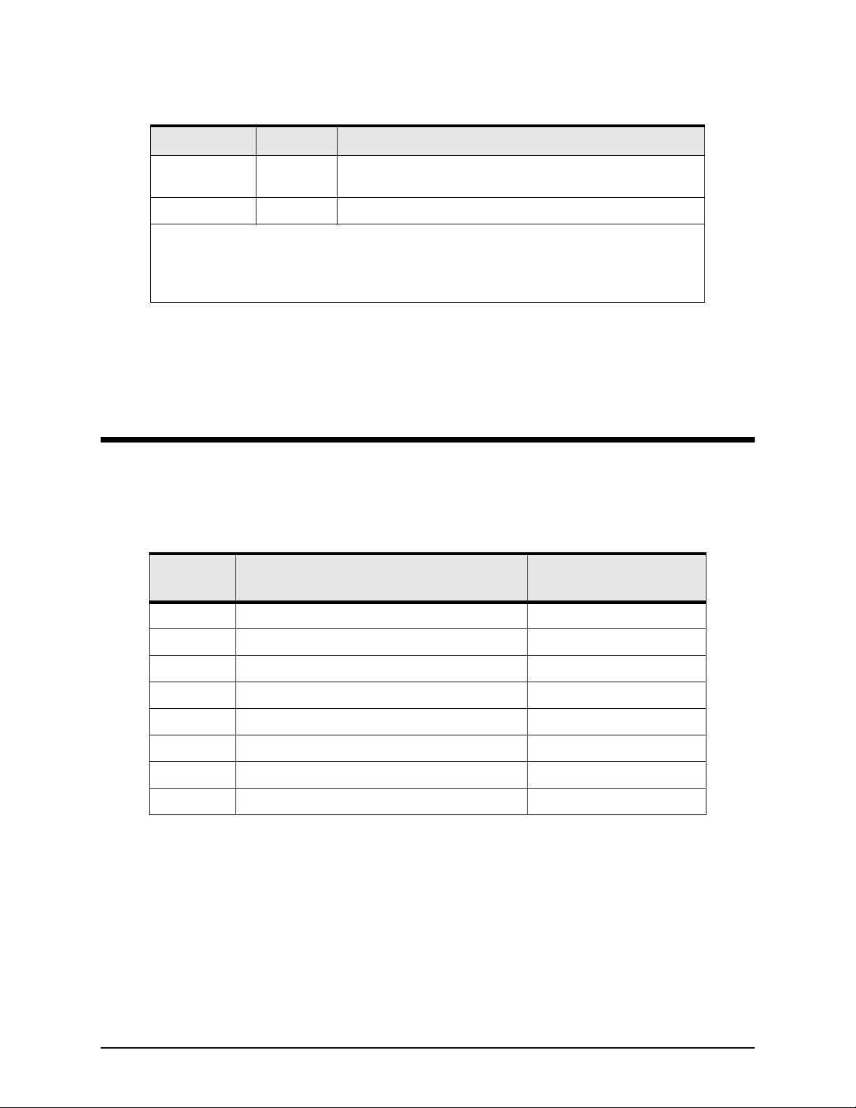
Appendix C NMEA output protocol
Table 6: NMEA field definitions (continued)
Field type Symbol Definition
Fixed number
field
Fixed text field cc_____ Fixed length field of valid characters
Notes:
1. Spaces can’t be used in variable text field.
2. A negative sign “-” (HEX 2D) is the first character in a Field if the value is negative.
The “+” sign is optional if value is positive.
Input sentences
Message
identifier
Name
xx_____ Fixed length field of numeric characters.
The following sections define the valid input and output
sentences available on the primary port.
Table 7 lists all valid input sentence types for the GPS receiver.
Detailed descriptions of each sentence are given in the sections
that follow.
Table 7: Primary port input messages
Maximum sentence
length (characters)
000 Configure Primary Port Command 17
001 Initialization Data Command 77
003 Initiate Self-test Command 15
004 Request Output Message Command 19
005 Set Output Configuration Command 67
006 Switch to Reprogramming Mode Command 20
007 Erase Non-Volatile Memory 18
MSK Command Message to Radiobeacon Board 27
Page 26 2505 INSTALLATION MANUAL, Revision A
Page 37
Appendix C NMEA output protocol
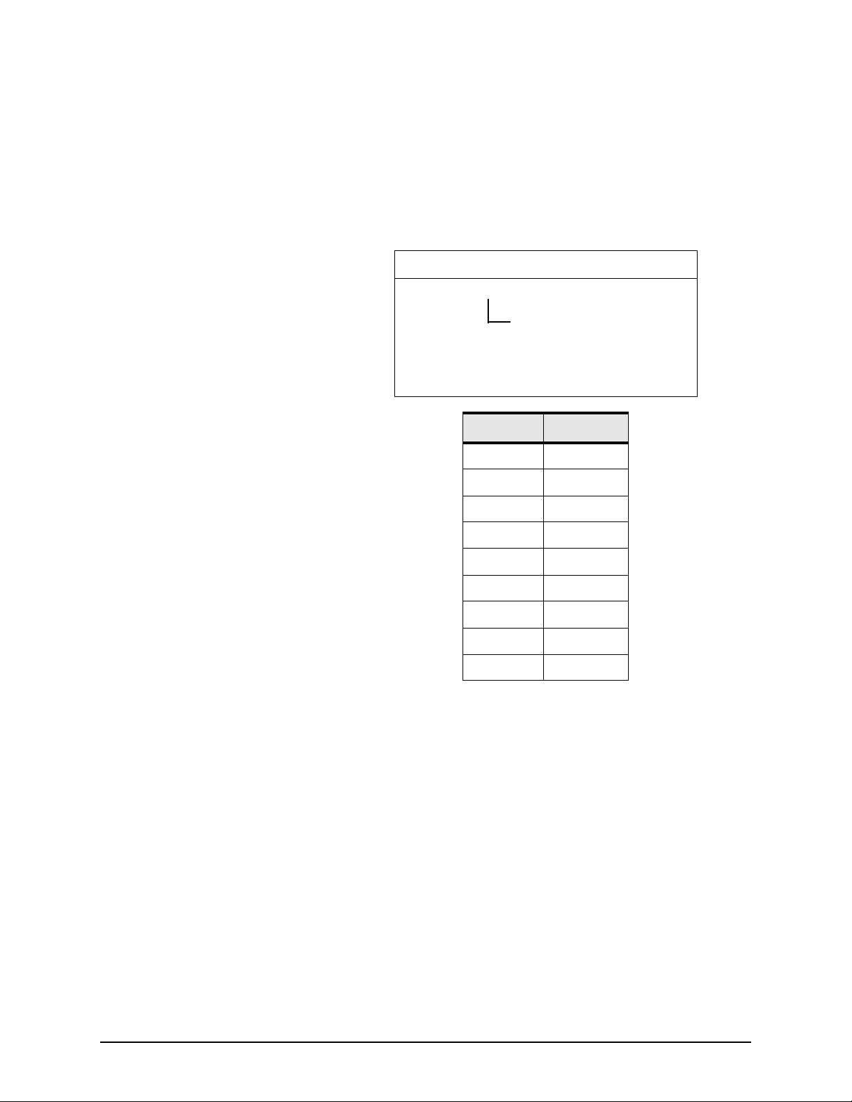
Configure primary port
command
This message is used to change the primary port mode. Once
this command is issued to the GPS receiver, the controller
supporting the Monitor mode protocol is activated, then NMEA
communications with the GPS receiver can be restored only by
using binary message #110. On power-up, with NVM, the
primary port stays in the same mode. Without NVM, the
default mode is Monitor Mode (CMC Binary).
HEADER CONTENTS OF DATA FIELDS
$PMCAG,000,x*hh<CR><LF>
baud rate selection1
Character Baud rate
0 19200
1300
2600
31200
42400
54800
69600
7 19200
8 38400
Example:
Configure the Primary Port to Monitor Mode at 19200.
$PMCAG,000,0*58<CR><LF>
2505 INSTALLATION MANUAL, Revision A Page 27
Page 38
Appendix C NMEA output protocol
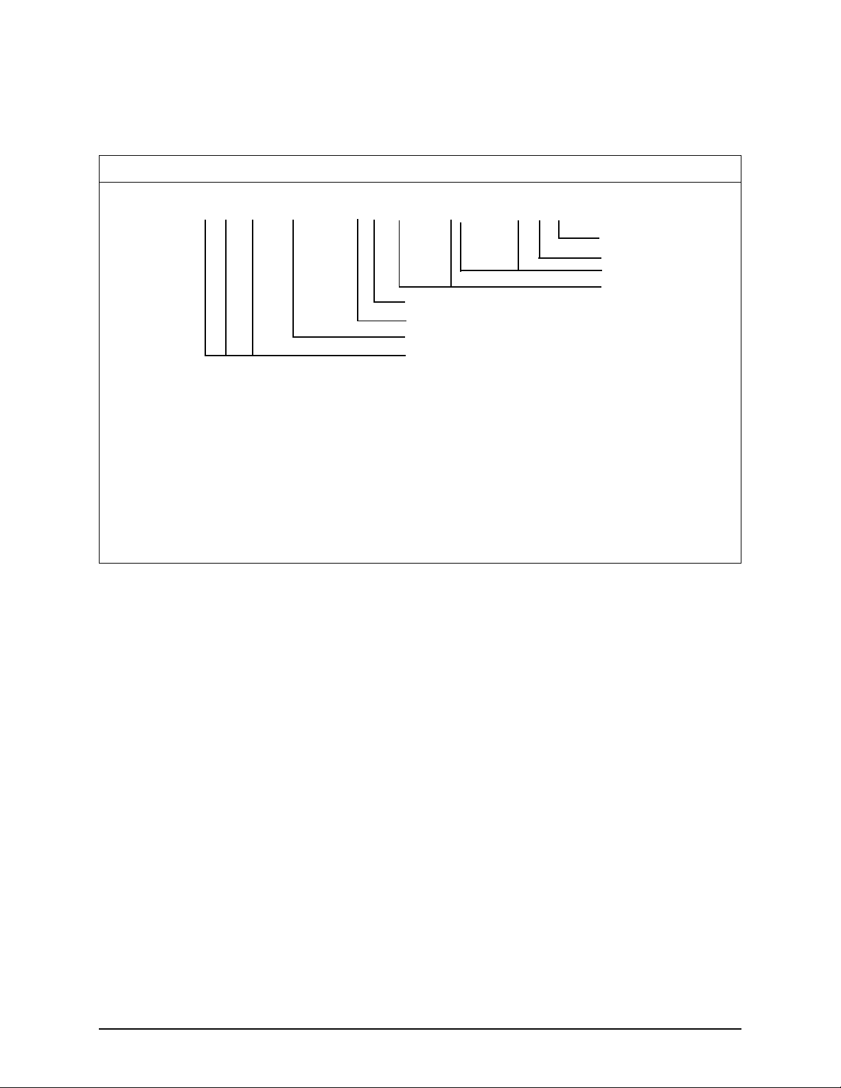
Initialization data
command
This message initializes the GPS receiver with reference UTC
date and time, and user position.
HEADER CONTENTS OF DATA FIELDS
$PMCAG,001,xx,xx,xxxx,hhmmss.ss,±xx,xx,±1111.11,a,yyyyy.yy,a,±x.x,c*hh<CR><LF>
reserved
altitude
longitude-E/W
reserved
reserved
time
date
1. UTC Date (Day 1...31, Month 1...12, Year 1980...2079
2. UTC Time (Hour 0...23, Minutes 0...59, Seconds 0...59)
3. Reserved, must be 0
4. Reserved, must be 00
5. Latitude - N/S with respect to WGS-84
6. Longitude - E/W with respect to WGS-84
7. Altitude in meters above (below) mean sea level; resolution: 0.01 meter
8. Reserved, no character
4
3
2
1
latitude-N/S
8
7
6
5
Example:
Set reference position sentence.
$PMCAG,001,09,07,1995,16,37,21,00,00,5301.97,N,00133.48,E,35.35,*6C<CR><LF>
Date 09/07/1995
Time 16:37:21
Reserved Must be 00
Local zone minutes Must be 00
Latitude 53° 01.97' North
Longitude 1° 33.48' East
Altitude 35.35 m above mean sea level
Reserved No character
Page 28 2505 INSTALLATION MANUAL, Revision A
Page 39
Appendix C NMEA output protocol
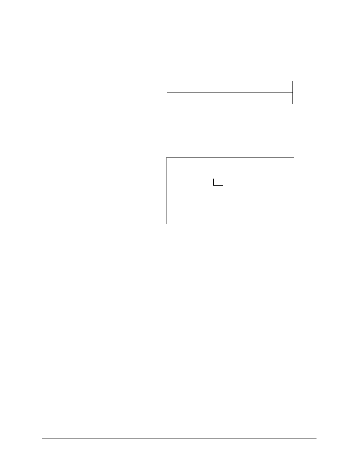
Initiate self-test command This message will request a complete self-test of the GPS
receiver. Results of the self-test will be automatically output
(output message 902) on the primary output port at completion
of the self-test sequence.
HEADER CONTENTS OF DATA FIELDS
$PCMG, 003*hh,CR><LF>
Example:
$PMCAG,003*47<CR><LF>
Request output message
command
HEADER CONTENTS OF DATA FIELDS
$PMCAG,004,ccc*hh<CR><LF>
sentence identifier
1
1. Valid sentence identifiers are those listed in
the next section (except message ID 901
and 902).
Example:
Request the approved sentence GPGGA.
$PMCAG,004,GGA*2D<CR><LF>
2505 INSTALLATION MANUAL, Revision A Page 29
Page 40

Appendix C NMEA output protocol
Set output configuration
command
HEADER CONTENTS OF DATA FIELDS
$PMCAG,005,x.x,ccc,xxx,...,ccc,xxxx*hh<CR><LF>
This message is used to configure the output of the primary
port. It contains the primary port baud rate and the list of
message identifiers with their minimum time interval between
consecutive transmissions.
Message types:
900 Navigation Status
GGA Global Positioning System Fix
Data
GLL Geographic Position - Latitude/
Longitude
GSA GPS DOP and Active Satellites
GSV GPS Satellites in View
RMC Recommended Minimum
Specific GPS Data
VTG Track Made Good and Ground
Speed
ZDA UTC Time & Date
nth message block
first message block
baud rate
1
2
2
1. Baud rate; valid baud rates: 0.3, 0.6, 1.2, 2.4, 4.8, 9.6, 19.2, 38.4 (in kBd units)
0 = keep the same baud rate (no effect)
1 = save the included list in NVM and overwrite the previous one
2. Message block; each message block includes:
ccc = message identifier
xxx = time interval between transmissions (1 to 999 seconds)
(000 will stop the transmission)
Examples:
$PMCAG,005,4.8,GGA,010,RMC,001,VTG,001,ZDA,010*48<CR><LF>
output messages:
GGA and ZDA transmitted every 10 seconds
RMC and VTG transmitted every second at 4800 baud
$PMCAG,005,1,GLL,001*2A<CR><LF>
output messages:
GGA and ZDA transmitted every 10 seconds
GGL, RMC and VTG transmitted every second at 4800
baud
GLL saved in NVM
Page 30 2505 INSTALLATION MANUAL, Revision A
Page 41

Switch to reprogramming
mode command
HEADER CONTENTS OF DATA FIELDS
$PMCAG,006,xx.x*hh<CR><LF>
baud rate
1. Baud rate: valid baud rates:
0.3, 0.6, 1.2, 2.4, 4.8, 9.6, 19.2 or 38.4
(in kBd units).
Example:
$PMCAG,006,19.2*7A<CR><LF>
Appendix C NMEA output protocol
1
2505 INSTALLATION MANUAL, Revision A Page 31
Page 42
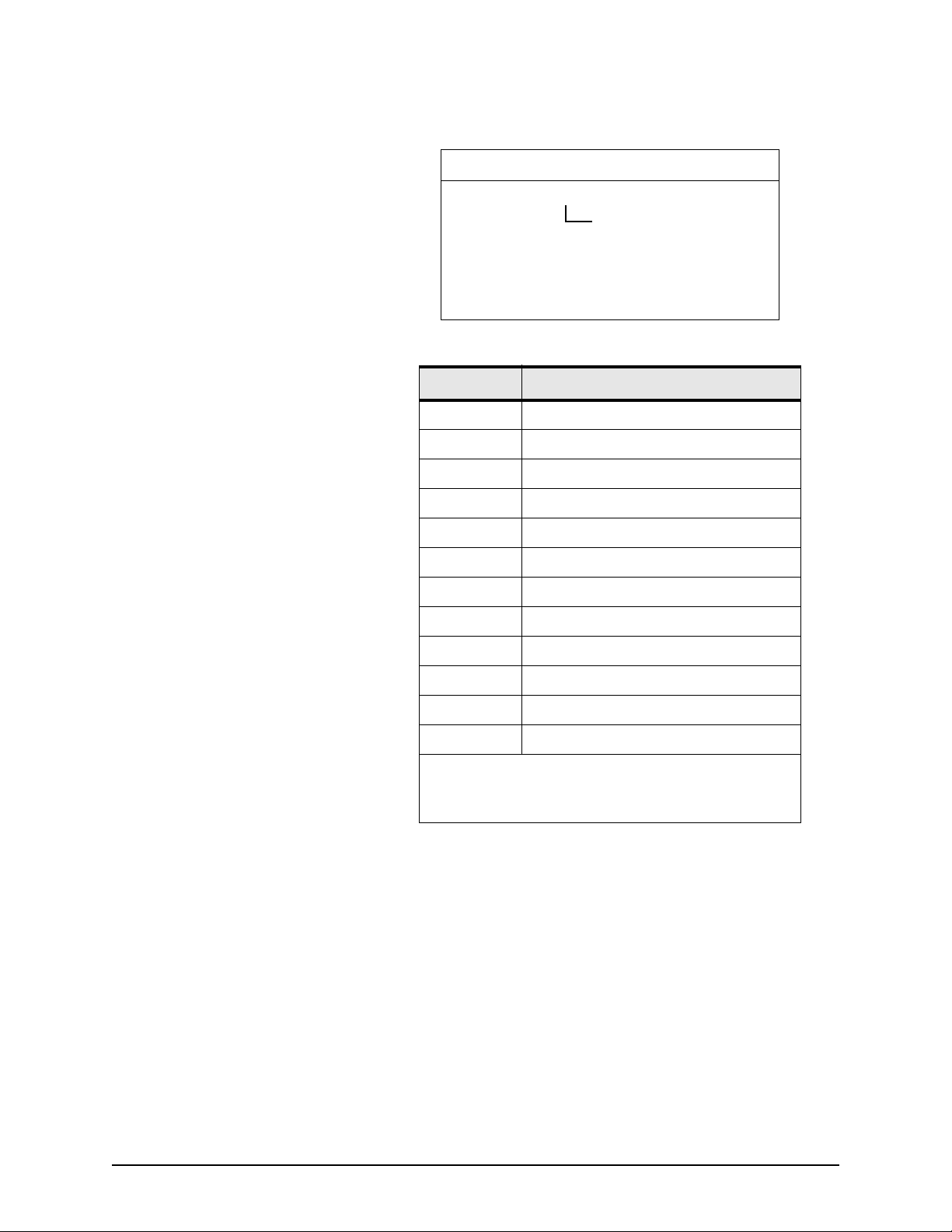
Appendix C NMEA output protocol
Erase non-volatile memory
command
HEADER CONTENTS OF DATA FIELDS
$PMCAG,007,xxx*hh<CR><LF>
element
1. Element: NVM element to erase as shown
in Table 8 below.
1
Table 8: NVM elements
Characters Element
00 All
01-04 Reserved
05 Almanac
06 Ionospheric data
1
07-08 Reserved
09 TCXO parameters
10 UTC parameters
11 Position
12 Time
13 DGPS configuration
14 Default NMEA message list
15 RS-232 configuration
1
1. This command will force the 2505 to go into
BSC binary mode, at 9600 baud, at the next
power-up.
Example:
$PMCAG,007,15*6B<CR><LF>
Erases configuration of the primary port and BSC binary
message list transmitted by default after each power-up.
Page 32 2505 INSTALLATION MANUAL, Revision A
Page 43

Appendix C NMEA output protocol
Command message to the
radiobeacon
HEADER CONTENTS OF DATA FIELDS
MSK,x.x,a,x.x,a,x.x*hh<CR><LF>
1. Status request: When status data I not to be transmitted, this field is “null.”
This message is used to configure the set the frequency and bit
rate parameters of the radiobeacon and also to set the rate of
the output message MSS and $PMCAG,903.
interval for sending $PCMCAG,903 and
MSS message in seconds
auto/manual bit rate
beacon bit rate (25, 50, 100, 200) bits per
second
auto/manual frequency A/M
radiobeacon frequency, 285.5 to 325.0 kHz
Example:
$GPMSK,288.0,A,100,A,004*6b<CR><LF>
Output messages:
MSS and 903 transmitted every 4 seconds.
Set the frequency to 288.0 in automatic mode, and bit
rate to 100 in automatic mode.
2505 INSTALLATION MANUAL, Revision A Page 33
Page 44
Appendix C NMEA output protocol
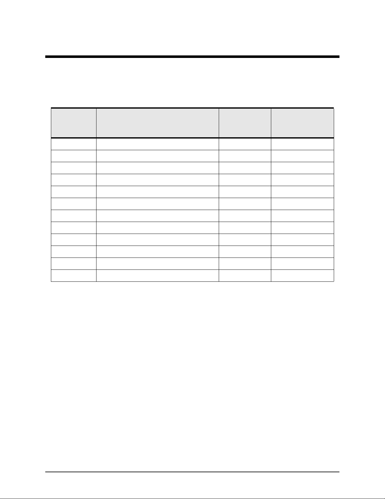
Output sentences
Table 9 below lists all valid output sentence types for the GPS
receiver. Detailed descriptions of each are given in the
following sections.
Table 9: Primary port output sentences
Message
identifier
900 Navigation status 21 Adjustable
901 Data request list overflow 15 N/A
902 Self-test results 39 On request
903 Radiobeacon proprietary info 40 Adjustable (via MSK)
GGA Global positioning system fix data 82 Adjustable
GLL Graphic position—latitude/longitude 51 Adjustable
GSA GPS DOP and active satellites 66 Adjustable
GSV GPS satellites in view 3*70 Adjustable
MSS MSS radiobeacon receiver signal status 29 Adjustable (via MSK)
Name
Maximum
sentence
length (chars)
Rate
RMC Recommended minimum specific GPS data 69 Adjustable
VTG Track made good and ground speed 37 Adjustable
ZDA UTC time and date and local time zone 39 Adjustable
Page 34 2505 INSTALLATION MANUAL, Revision A
Page 45

Appendix C NMEA output protocol
Navigation status This message provides the current navigation mode and GPS
fix quality indicator.
HEADER CONTENTS OF DATA FIELDS
$PMCAG,900,ccc,c*hh<CR><LF>
GPS fix quality indicator
navigation mode
1. Navigation mode:
3DD 3-D fix with differential aiding
3-D 3-D fix
2-DD 2-D fix (constant altitude) with differential aiding
2-D 2-D fix (constant altitude)
D-R dead-reckoning
INI initialization (from last good fix or external
initialization
1
2
NCD no compound data; fix data is not valid and
should be ignored
The GPS sensor doesn’t have a valid time and/or a valid
position (from last good fix or external initialization).
2. GPS fix quality indicator:
L = Low (Navigation solution is obtained from fewer than
5 satellite measurements.)
H = High (Navigation solution is obtained from at least 5
satellite measurements.)
Example:
$PMCAG,900,3-D,H*5F<CR><LF>
Navigation mode:
3-D fix (GPS fix obtained from at least 5 satellites).
2505 INSTALLATION MANUAL, Revision A Page 35
Page 46

Appendix C NMEA output protocol
Data request list overflow This message is returned when more than eight data requests
are pending.
HEADER CONTENTS OF DATA FIELDS
$PMCAG,901*hh<CR><LF>
Example:
$PMCAG,901*4C<CR><LF>
Page 36 2505 INSTALLATION MANUAL, Revision A
Page 47

Appendix C NMEA output protocol
Self-test results message Result of the GPS sensor self-test. This message is automatically
output in response to an initiated self-test request (see input
message identifier 003). This message can also be requested
through input message identifier 004 to retrieve the current
status of the sensor without initiating a self-test sequence.
HEADER CONTENTS OF DATA FIELDS
$PMCAG,902,xxxxxx,xxx,a,aaaa,xx,xx*hh<CR><LF>
faults identifier
number of active faults
sensor self-test result
software revision letter
software variation number
software part number (root number)
1. Sensor self-test result from the last initiated test (PASS, FAIL)
1
Examples:
$PMCAG,902,613913,042,A,PASS,00,63*23<CR><LF>
$PMCAG,902,613913,042,A,FAIL,03,49*3B<CR><LF>
2505 INSTALLATION MANUAL, Revision A Page 37
Page 48
Appendix C NMEA output protocol
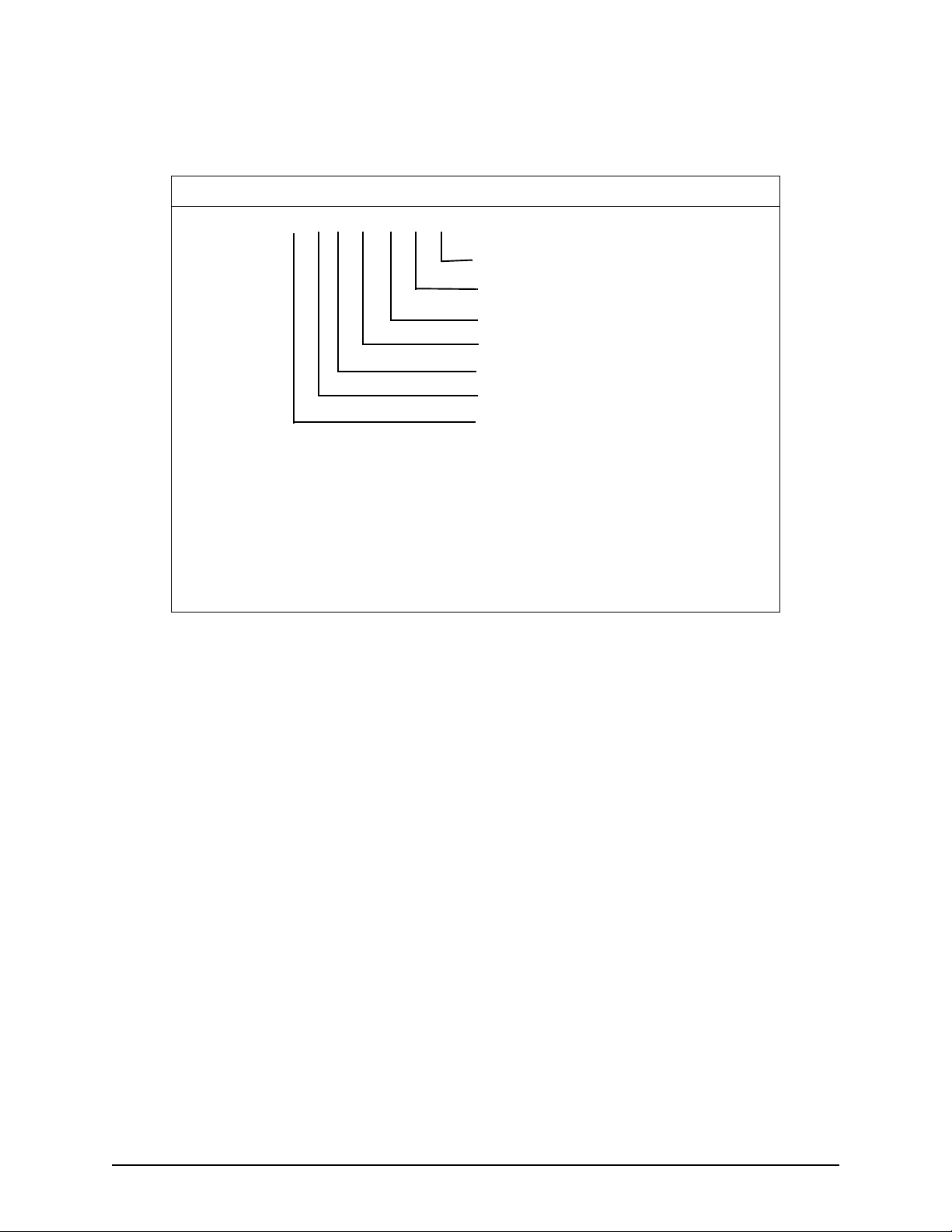
Radiobeacon proprietary
information
HEADER CONTENTS OF DATA FIELDS
$PMCAG,903,x.x,aa,x.x,x.x,x.x,x.x,x.x*hh<CR><LF>
1. 0s means all test passed
bit 0 antenna fault default
bit 1 battery-backed RAM invalid
This message is automatically output in response to an MSK
request (see input message identifier MSK).
reserved (shall be null)
reserved (shall be null)
reserved (shall be null)
reserved (shall be null)
software part number (root number)
radiobeacon self-test result
impulse noise count
1
bits 2-5 reserved
Example:
$GPCAG,903,6,,2.24,0,0,0,0*62<CR><LF>
Page 38 2505 INSTALLATION MANUAL, Revision A
Page 49
Appendix C NMEA output protocol
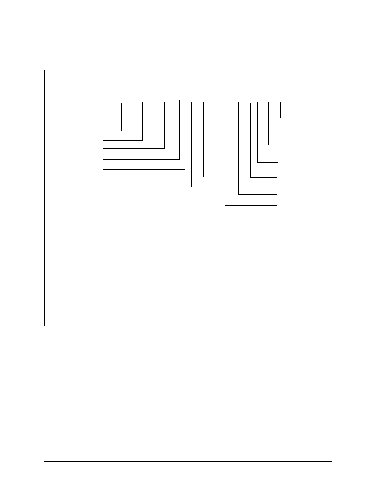
Global positioning system
fix data
HEADER CONTENTS OF DATA FIELDS
$GPGGA,hhmmss . s s , 1111.1111,a,yyyyy. y y y y, a,x,xx,xx.x, ±x x x x x.x,M,xxxx,M,x x x x , x xxx*hh<CR><LF >
UTC of position
latitude
N/S—North or South
longitude
E/W—East or West
quality indicator
differential reference
1
2
3
HDOP
SVs in use
1. Latitude with respect to WGS-84:
2 digits of degrees, 2 digits of minutes, 4 digits of decimal fraction of minutes.
2. Longitude with respect to WGS-84:
3 digits of degrees, 2 digits of minutes, 4 digits of decimal fraction of minutes
3. GPS quality indicator:
0 = fix not available or invalid
1 = GPS fix
2 = Differential GPS fix
4. May be different from number in view
5. Altitude with respect to mean sea level
6. Geoidal separation: the difference between the WGS-84 earth ellipsoid and
mean-sea-level (geoid); if negative, mean-sea-level is below ellipsoid
7. Time (in seconds) since last SC104 Type 1 or 9 update; empty field when DGPS
is not used
4
station ID
(0000-1023)
age of differential
GPS data
units of geoidal
separation, meters
geoidal separation
units of antenna
altitude, meters
altitude
7
5
6
Example:
$GPGGA,012338.61,5619.2837,N,17235.8964,E,1,05,02.3,-00034.2,M,,M,,*66<CR><LF>
UTC 01:23:38.61
Latitude 56° 19.2837' North
Longitude 172° 35.8964' East
Quality GPS fix
Satellites used 5
HDOP 2.3
Altitude3 4.2 m below mean sea level
2505 INSTALLATION MANUAL, Revision A Page 39
Page 50
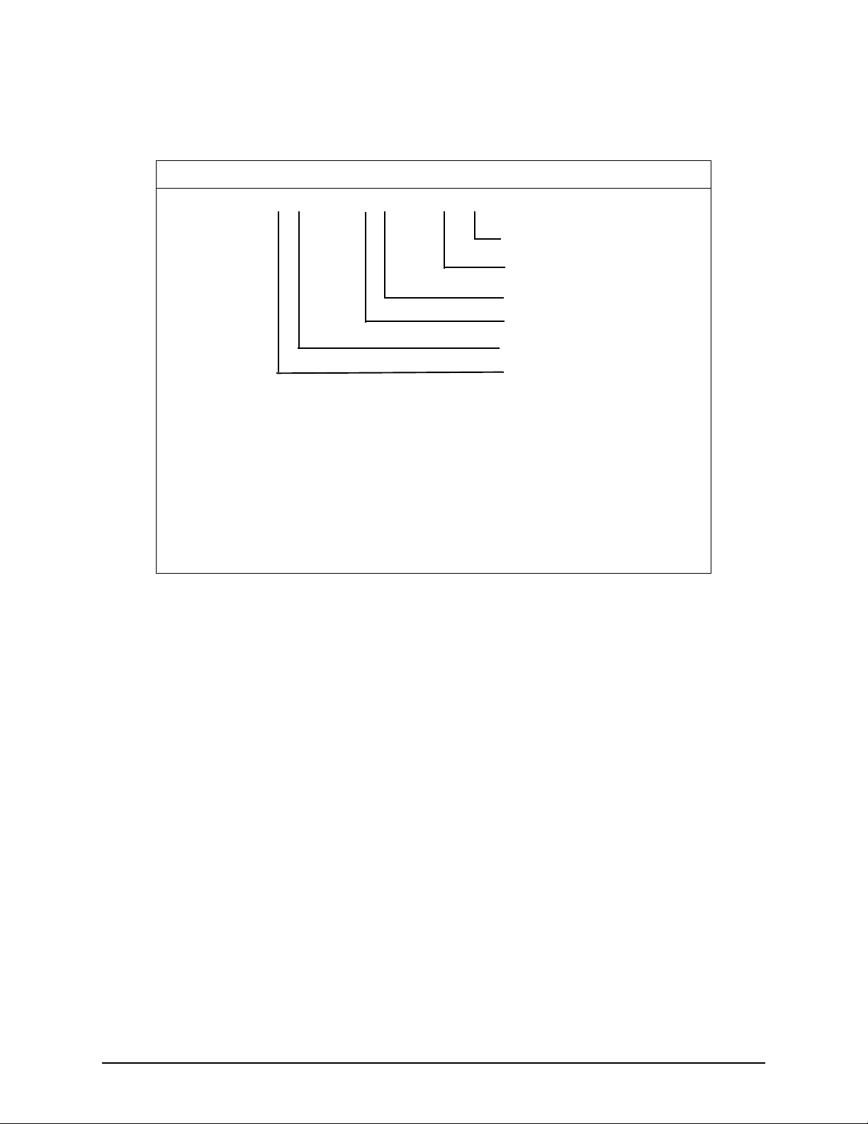
Appendix C NMEA output protocol
Geographic position
latitude/longitude
Latitude and longitude of present position, time of position and
status.
HEADER CONTENTS OF DATA FIELDS
$GPGLL,1111.1111,a,y y y y y.yyyy,a,hhmmss.s s , A*hh<CR><LF>
status
UTC of position
E/W—East or West
longitude
N/S —North or South
latitude
1. Latitude with respect to WGS-84:
2 digits of degrees, 2 digits of minutes, 4 digits of decimal fractions of
minutes
2. Longitude with respect to WGS-84:
3 digits of degrees, 2 digits of minutes, 4 digits of decimal fractions of
minutes
3. Status:
A = data valid
V = data invalid
3
2
1
Example:
$GPGLL,5619.2837,N,17235.8964,E,012338.61,A*0C<CR><LF>
Latitude: 56° 19.2837' North
Longitude: 172° 35.8964' East
UTC: 01:23:38.61
Status: Valid Data
Page 40 2505 INSTALLATION MANUAL, Revision A
Page 51
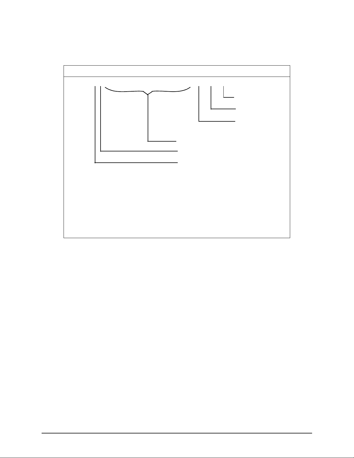
Appendix C NMEA output protocol
GPS DOP and active
satellites
Operating mode, satellites used for navigation and DOP values
from GPS sensor.
HEADER CONTENTS OF DATA FIELDS
$GPGSA,a,x,xx,xx,xx,xx,xx,xx,xx,xx,xx,xx,xx,xx,xx.x,xx.x,xx.x*hh<CR><LF>
VDOP
HDOP
PDOP
PRNs of SVs used
2
mode
3
mode
1. PRN numbers of satellites used in solution (null for unused fields).
2. Mode:
1 = fix not available
2 = 2-D
3 = 3-D
3. Mode:
M = manual, forced to operate in 2-D or 3-D mode
A = automatic, allowed to automatically switch 2-D/3-D
1
Example:
$GPGSA,A,3,14,22,03,09,08,29,17,,,,,,2.7,2.2,1.6*3A<CR><LF>
Mode: automatic/3-D
SVs Used: PRNs 14, 22, 03, 09, 08, 29, 17
PDOP: 2.7
HDOP: 2.2
VDOP: 1.6
2505 INSTALLATION MANUAL, Revision A Page 41
Page 52
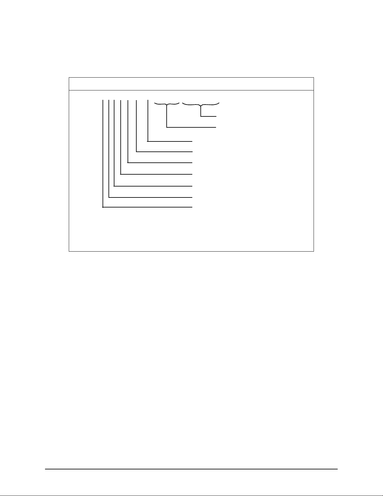
Appendix C NMEA output protocol
GPS satellites in view Number of SVs in view, PRN numbers, elevation, azimuth and
SNR values. Four satellites maximum per transmission,
additional satellite data sent in second or third sentence.
HEADER CONTENTS OF DATA FIELDS
$GPGSV,x,x,xx,xx,xx,xxx,xx.x...........,xx,xx,xxx,xx.x*hh<CR><LF>
4th SV
2nd to 3rd SV
1
SNR
azimuth, degrees
elevation, degrees
satellite PRN number
total number of satellites in view
message number, 1 to 3
total number of messages, 1 to 3
2
3
1. SNR (C/N
2. Azimuth, range 000 to 359 degrees
3. Elevation, range 00 to 90 degrees
) 00.0-99.9 dB, null when not tracking
o
Examples:
$GPGSV,2,1,06,03,12,238,06.0,07,82,008,15.5,11,04,053,,27,43,178,12.3*67<CR><LF>
Messages 2
Msg. No. 1
SV Visible 6
PRN 03
Elevation 12°
Azimuth 238°
SNR 6 dB
PRN 07
Elevation 82°
Azimuth 8°
SNR 15.5 dB
PRN 11
Elevation 4°
Azimuth 53°
SNR Not tracked
PRN 27
Elevation 43°
Azimuth 178°
SNR 12.3 dB
Page 42 2505 INSTALLATION MANUAL, Revision A
Page 53

Appendix C NMEA output protocol
$GPGSV,2,2,06,15,23,187,8.2,17,35,323,11.1,,,,,,,,*4D<CR><LF>
Messages 2
Msg. No. 2
SV Visible 6
PRN 15
Elevation 23°
Azimuth 187°
SNR 8.2 dB
PRN 17
Elevation 35°
Azimuth 323°
SNR 11.1 dB
2505 INSTALLATION MANUAL, Revision A Page 43
Page 54

Appendix C NMEA output protocol
MSS receiver signal status This message sends the information about the signal-to-noise
ratio and signal strength frequency and bit rate from an MSK
(beacon) receiver. This message will be transmitted at the rate
set in the message $GPCAG,MSK.
HEADER CONTENTS OF DATA FIELDS
$GPMSS,x.x,x.x,x.x,x.x*hh<CR><LF>
beacon bit rate (25, 50, 100, 200) bits per second
radiobeacon frequency, 285.5 to 325.0 kHz
signal-to-noise ration (SNR), dB
signal strength (SS), dB re: 1 uv/m
Example:
$GPMSS,32,13,288.0,100,*68<CR><LF>
Page 44 2505 INSTALLATION MANUAL, Revision A
Page 55

Appendix C NMEA output protocol
Recommended minimum
specific GPS data
HEADER CONTENTS OF DATA FIELDS
$GPRMC,hhmmss.ss , A , 1111 .1111,a,yyyyy.y y y y, a , xxx.x,xxx.x,x x x x xx,,*hh<CR><LF >
1. Date:
2 digits for day, 2 digits for month and 2 digits for year (ddmmyy)
2. The track made good, measured in clockwise-from-North direction, at the
current position:
Range 0-360 degrees.
3. Longitude:
3 digits of degrees, 2 digits of minutes, 4 digits of decimal fraction of
minutes
4. Latitude:
2 digits of degrees, 2 digits of minutes, 4 digits of decimal fraction of
minutes
5. Status:
A = data valid
V = nav receiver warning.
Time, date, position, course and speed data.
date
track
speed, knots
E/W—East or West
longitude
N/S—North or South
latitude
status
UTC of position fix
3
4
5
1
2
Example:
Recommended minimum specific GPS data sentence.
$GPRMC,224512.45,G,2518.3847,S,08339.8367,E,003.8,311.5,080793,,*2E<CR><LF>
UTC 22:45:12.45
Status Good
Latitude 25° 18.3847' South
Longitude 083° 39.8367' East
Speed 3.8 knots
Heading 311.5° from North
Date 08/07/93
2505 INSTALLATION MANUAL, Revision A Page 45
Page 56
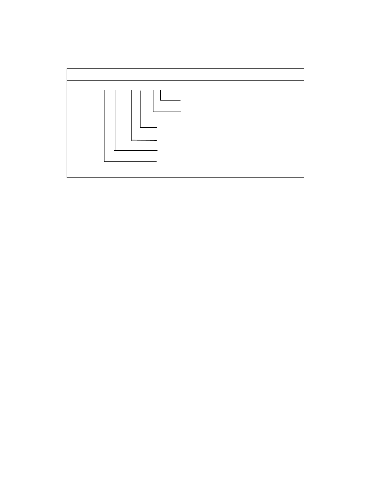
Appendix C NMEA output protocol
Track made good and
Actual track made good and speed relative to the ground.
ground speed
HEADER CONTENTS OF DATA FIELDS
$GPVTG,xxx.x,T,,,xxx.x,N,xxx.x,K*hh<CR><LF>
km/hr
speed
knots
speed
degrees true
track
Example:
Track made good and ground speed data sentence.
$GPVTG,234.6,T,,,075.3,N,139.5,K*21<CR><LF>
Track 23 4.6° from North
Speed 75.3 knots
Speed 139.5 km/hr
Page 46 2505 INSTALLATION MANUAL, Revision A
Page 57

Time and date UTC time, date and local time zone.
HEADER CONTENTS OF DATA FIELDS
$GPZDA,hhmmss.ss,xx,xx,xxxx,xx,xx,K*hh<CR><LF>
Appendix C NMEA output protocol
local zone minutes description
local zone description
year
month
day
UTC time
1. Zone description is the number of whole hours added to local time to obtain
UTC; zone description is negative for East longitudes (00...±13 hours)
2. Local zone minutes (00...59); same sign as local hours
1
2
Example:
Time and date sentence.
$GPZDA,224512.45,12,01,2003,–6,00,*hh<CR><LF>
UTC 22:45:12.45
Date 12 January 2003
Local zone 6 zones (hours) East of GMT
2505 INSTALLATION MANUAL, Revision A Page 47
Page 58

Appendix C NMEA output protocol
Page 48 2505 INSTALLATION MANUAL, Revision A
Page 59
Glossary
Almanac The compilation of satellite identification and orbital data used
by a GPS receiver.
Beacon A land-based differential correction transmitter, also known as
a U. S. Coast Guard beacon.
BDM Beacon DeModulator, which is the receiver for differential
correction signals.
C/No Carrier to Noise Density Ratio.
CMC Canadian Marconi Company.
DRMS Distance Root Mean Square.
EEPROM Electrically Erasable Programmable Read Only Memory.
HDOP Horizontal Dilution of Precision.
Host Customer system receiving position data from the 2505.
L1 The frequency band used by the GPS sensor, 1575MHz.
2505 INSTALLATION MANUAL, Revision A Page 49
Page 60

Glossary
MF Medium Frequency band.
MHz MegaHertz, one million cycles per second.
MSB Most Significant Bit.
MSK Minimum Skift Keying (the type of modulation used by the
BDM, about 50 Hz shift).
NVM Non-Volatile Memory.
PAL Programmed Array Logic chip.
PRN Pseudo Random Number (satellite ID number).
RAM Random Access Memory.
RMS Root Mean Square.
RTCM Radio Technical Commission for Maritime Services, for
standards and performance minimums.
SC-104 The communication specification for differential corrections
format.
TNC The type of connector used by the GPS antenna.
TTFF Time To First Fix.
VDOP Vertical Dilution of Precision
WA AS Wide Area Augmentation System (differential corrections via
geostationary satelliteS)
WGS–84 World Geodetic System—1984 (datum)
Page 50 2505 INSTALLATION MANUAL, Revision A
 Loading...