

Page 1
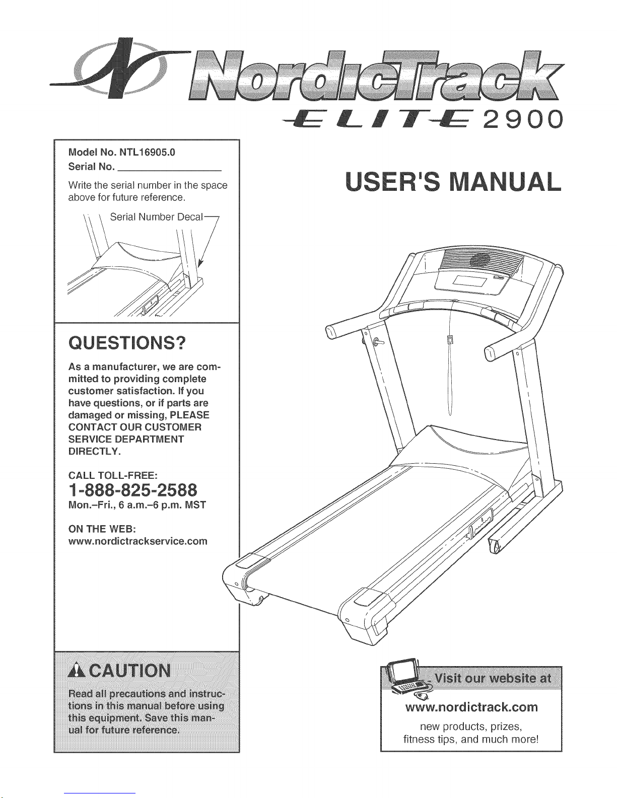
Mode_ No. NTL16905°0
Seria_ No.
2900
Write the serial number in the space
above for future reference.
Serial
QUESTIONS?
As a manufacturer, we are com-
mitted to providing complete
customer satisfaction, if you
have questions, or if parts are
damaged or missing, PLEASE
CONTACT OUR CUSTOMER
SERVICE DEPARTMENT
DIRECTLY°
CALL TOLL-FREE:
1°888°825°2588
Mon°-FrL, 6 a°m°-6 p.m. MST
'S
ON THE WEB:
www°nordictrackservice°com
www.nordictrack.com
new products, prizes,
fitness tips, and much more!
Page 2

2900
TABLE OF CONTENTS
IMPORTANT PRECAUTRONS ................................................................. 3
BEFORE YOU BEGRN ....................................................................... 5
ASSEMBLY ............................................................................... 6
TREADMRLL OPERATRON ................................................................... 11
HOW TO FOLD AND MOVE THE TREADMRLL .................................................. 25
TROUBLESHOOTRNG ...................................................................... 27
EXERCRSE GURDEUNES ................................................................... 29
PART UST ............................................................................... 30
HOW TO ORDER REPLACEMENT PARTS ..................................................... 31
UMFED WARRANTY ............................................................... Back Cover
Note: An EXPLODED DRAWRNG is attached in the center of this manual.
NordicTrack is a registered trademark of RCON RP,Rnc.
Page 3

iMPORTANT PRECAUTIONS
3
Page 4
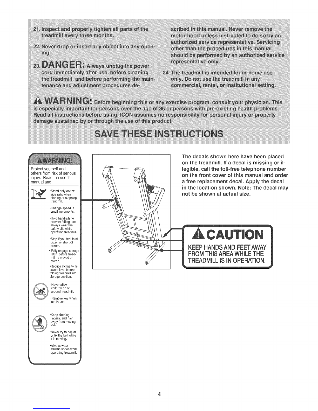
Protect yourself and
others from risk of serious
injury. Read the user's
manual and :
,Stand oniy on the
side raiis when
starting or stopping
treadmill.
.Change speed in
small increments.
•HoHd handrails to
prevent famiing, and
aiways wear the
safety dip while
operating treadmill
•Stop if you feel faint,
dizzy, or short of
breath.
Fully engage storage
Hatch before tread-
miil is moved or
stored.
•Reduce incline to its
lowest level before
folding treadmiHHinto
storage position.
•Never aHBow
chimdren on or
around treadmiHL
•Removekey when
not in use.
The deca_s shown here have been pmaced
on the treadmi& if a decam is missing or iF
_egib_e, calmthe tomFfree temephone number
on the front cover of this manua_ and order
a free replacement decal Apply the deca_
in the location shown. Note: The deca_ may
not be shown at actua_ size.
KEEPHANDSAND FEETAWAY
FROMTHHSAREAWHILETHE
TREADMILLISIN OPERATMON,
,Keep clothing,
fingers, and hair
away from moving
beHt.
,Never try to adjust
or fix the beHtwhiHe
it is moving.
,AHways wear
athHetic shoes whime
operating treadmiHL
4
Page 5
BEFORE YOU BEGUN
Thank you for selecting the revolutionary NordicTrack _
ELITE 2900 treadmill. The ELITE 2900 treadmill offers
an impressive selection of features designed to make
your workouts at home more enjoyable and effective.
And when you're not exercising, the unique ELITE
2900 treadmill can be folded up, requiring less than half
the floor space of other treadmills.
For your benefit, read this manua_ carefully before
using the treadmill. If you have questions after read-
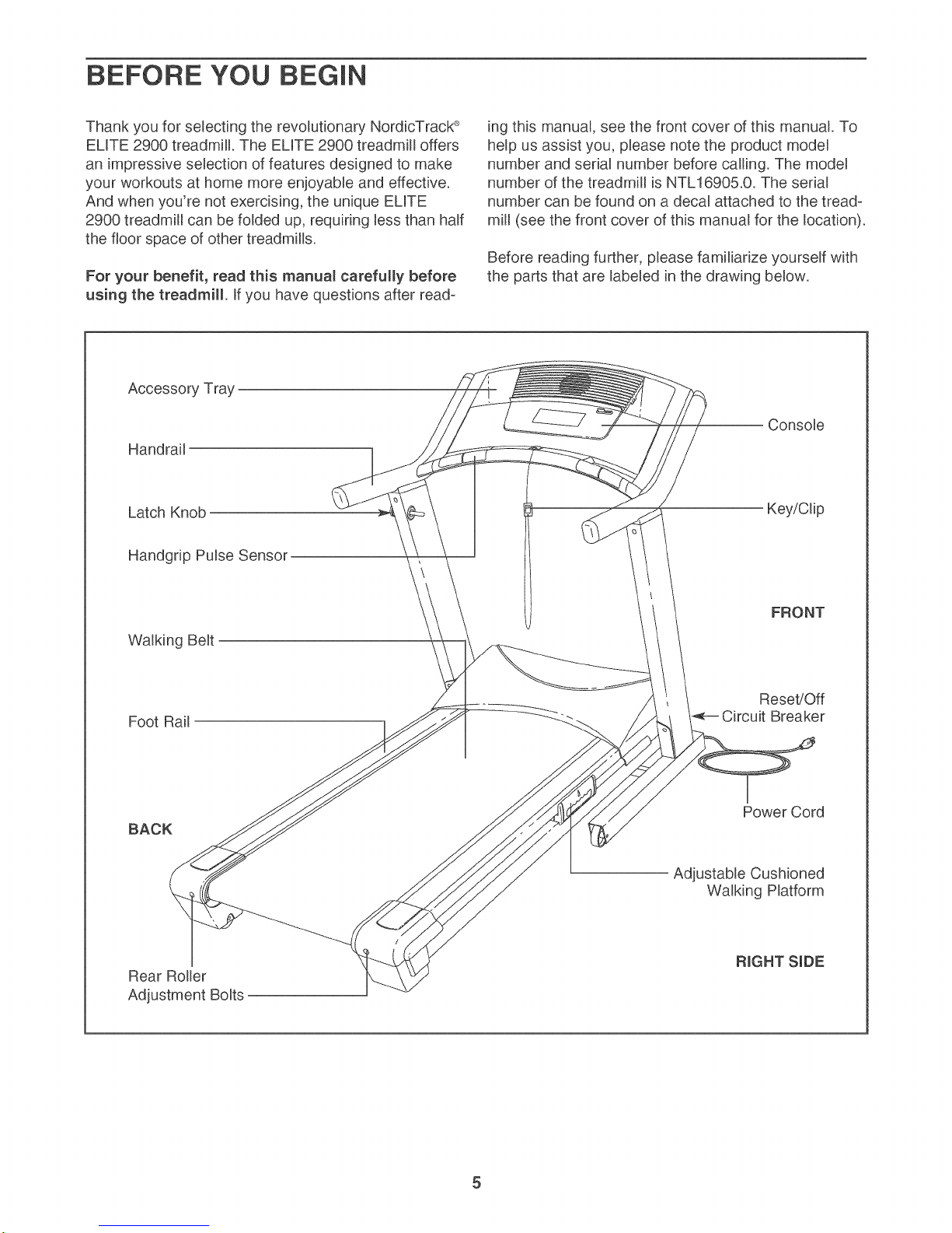
Accessory Tray
Handrail
Latch Knob
Handgrip Pulse Sensor
ing this manual, see the front cover of this manual. To
help us assist you, please note the product model
number and serial number before calling. The model
number of the treadmill is NTL16905.0. The serial
number can be found on a decal attached to the tread-
mill (see the front cover of this manual for the location).
Before reading further, please familiarize yourself with
the parts that are labeled in the drawing below.
Key/Clip
Walking Belt
Foot Rail
BACK
Rear Roller
Adjustment Bolts
FRONT
Reset!Off
Breaker
Power Cord
Adjustable Cushioned
Walking Platform
Page 6
Assemblyrequirestwopersons.Setthetreadmillinaclearedareaandremoveallpackingmaterials.Donot
disposeofthepackingmaterialsuntilassemblyiscompleted.Note:Theundersideofthetreadmillwalkingbeltis
coatedwithNgh_performancelubricant.Duringshipping,asmallamountoflubricantmaybetransferredtothe
topofthewalkingbeltorthesNppingcarton.Thisisanormalconditionanddoesnotaffecttreadmillperfor-
mance.Ifthereislubricantontopofthewalkingbelt,simplywipeoffthelubricantwitha softclothandamild,
non-abrasivecleaner.
[
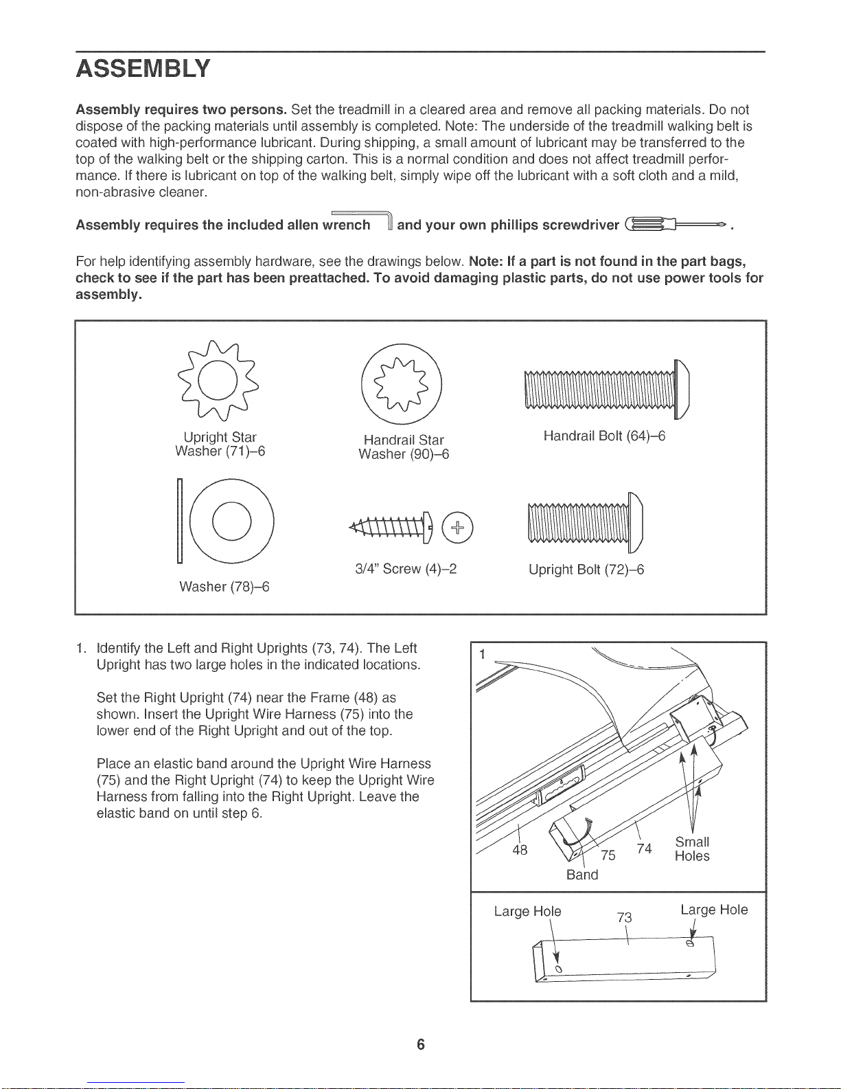
Assembly requires the included allen wrench _ and your own phillips screwdriver
For help identifying assembly hardware, see the drawings below. Note: If a part is not found in the part bags,
check to see if the part has been preattached. To avoid damaging p_astic parts, do not use power too_s for
assembly.
Upright Star Handrail Star
Washer (71)-6 Washer (90)-6
Washer (78)-6
1. Identify the Left and Right Uprights (73, 74). The Left
Upright has two large holes in the indicated locations.
Set the Right Upright (74) near the Frame (48) as
shown. Insert the Upright Wire Harness (75) into the
lower end of the Right Upright and out of the top.
Place an elastic band around the Upright Wire Harness
(75) and the Right Upright (74) to keep the Upright Wire
Harness from falling into the Right Upright. Leave the
elastic band on until step 6.
Handrail Bolt (64)-6
Upright Bolt (72)-6
48
Large Hole
Band
73
74
Small
Holes
Large Hole
Page 7
,
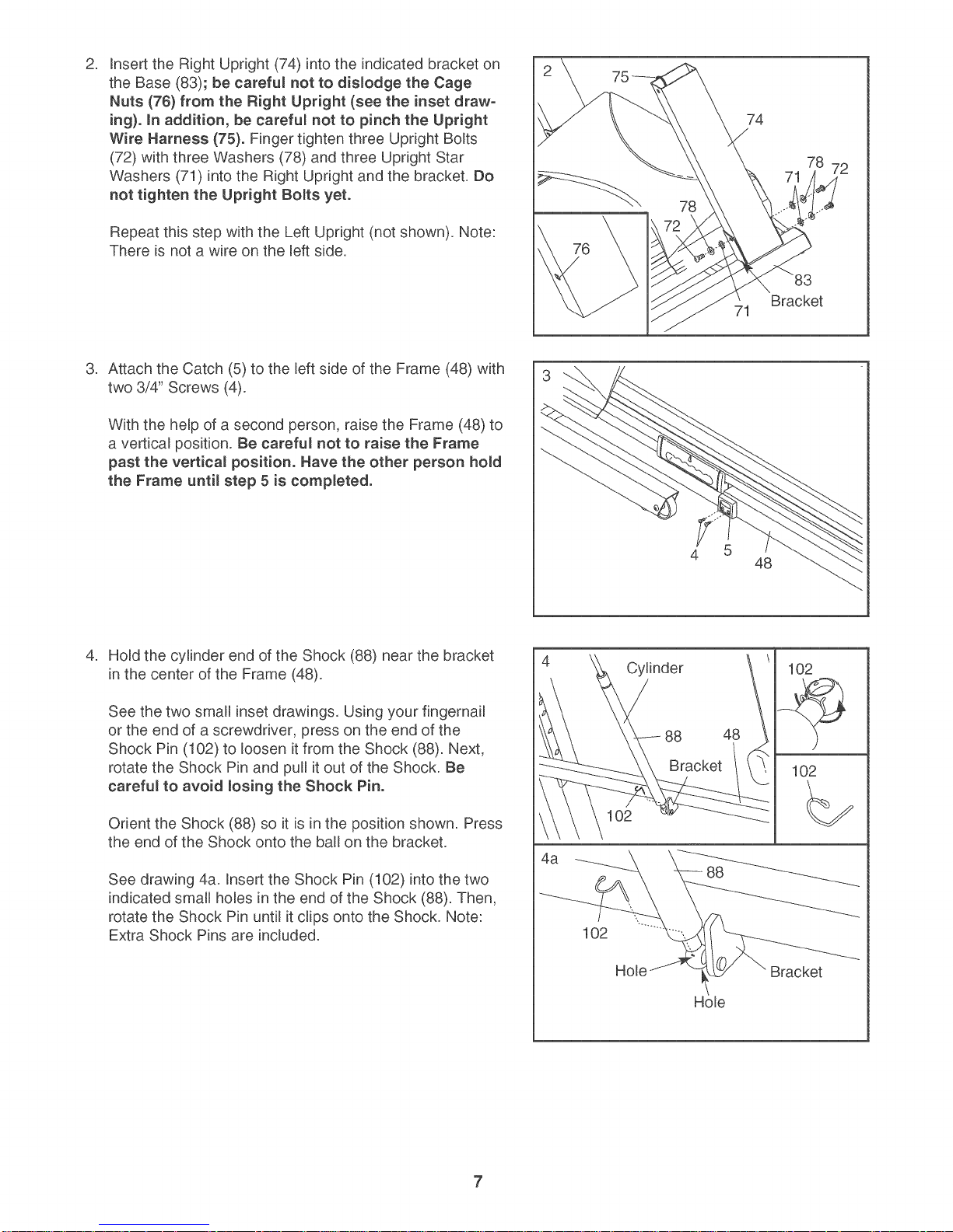
Insert the Right Upright (74) into the indicated bracket on
the Base (83); be careful not to dislodge the Cage
Nuts (76} from the Right Upright (see the inset draw-
ing). in addition, be careful not to pinch the Upright
Wire Harness (75)° Finger tighten three Upright Bolts
(72) with three Washers (78) and three Upright Star
Washers (71) into the Right Upright and the bracket. Do
not tighten the Upright Bolts yet.
Repeat this step with the Left Upright (not shown). Note:
There is not a wire on the left side.
,
Attach the Catch (5) to the left side of the Frame (48) with
two 3/4" Screws (4).
With the help of a second person, raise the Frame (48) to
a vertical position. Be careful not to raise the Frame
past the vertical position. Have the other person hold
the Frame until step 5 is completed°
74
78
Bracket
,
Hold the cylinder end of the Shock (88) near the bracket
in the center of the Frame (48).
See the two small inset drawings. Using your fingernail
or the end of a screwdriver, press on the end of the
Shock Pin (102) to loosen it from the Shock (88). Next,
rotate the Shock Pin and pull it out of the Shock. Be
careful to avoid losing the Shock Pin.
Orient the Shock (88) so it is in the position shown. Press
the end of the Shock onto the ball on the bracket.
See drawing 4a. Insert the Shock Pin (102) into the two
indicated small holes in the end of the Shock (88). Then,
rotate the Shock Pin until it clips onto the Shock. Note:
Extra Shock Pins are included.
4
Cylinder
48
102
88 48
Bracket 102
102
4a
Ho_e
7
Page 8
.
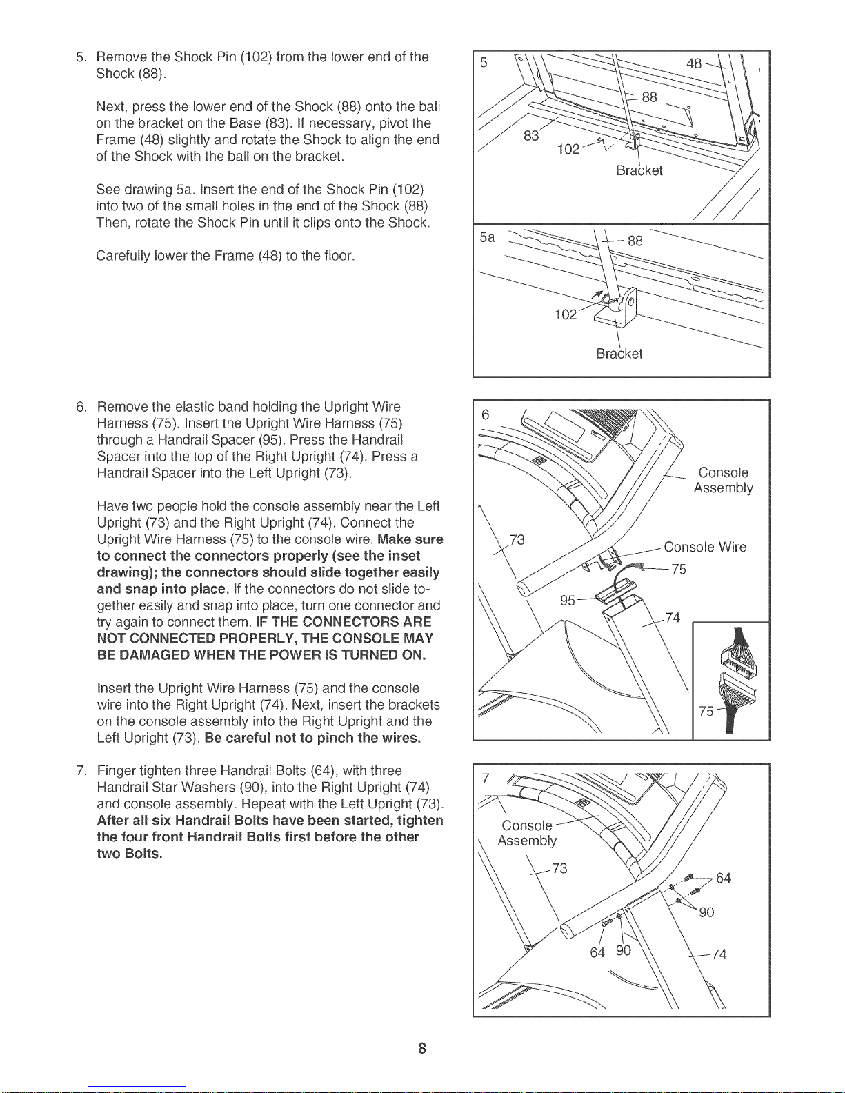
Remove the Shock Pin (102) from the lower end of the
Shock (88).
Next, press the lower end of the Shock (88) onto the ball
on the bracket on the Base (83). ff necessary, pivot the
Frame (48) slightly and rotate the Shock to align the end
of the Shock with the ball on the bracket.
See drawing 5a. insert the end of the Shock Pin (102)
into two of the small holes in the end of the Shock (88).
Then, rotate the Shock Pin until it clips onto the Shock.
Carefully lower the Frame (48) to the floor.
.
Remove the elastic band holding the Upright Wire
Harness (75). Insert the Upright Wire Harness (75)
through a Handrail Spacer (95). Press the Handrail
Spacer into the top of the Right Upright (74). Press a
Handrail Spacer into the Left Upright (73).
Have two people hold the console assembly near the Left
Upright (73) and the Right Upright (74). Connect the
Upright Wire Harness (75) to the console wire. Make sure
to connect the connectors proper_y (see the inset
drawing}; the connectors should s_ide together easily
and snap into p_ace° If the connectors do not slide to-
gether easily and snap into place, turn one connector and
try again to connect them. IF THE CONNECTORS ARE
NOT CONNECTED PROPERLY, THE CONSOLE MAY
BE DAMAGED WHEN THE POWER IS TURNED ON.
"ket
5a
88
Console
Assembly
73
Wire
Insert the Upright Wire Harness (75) and the console
wire into the Right Upright (74). Next, insert the brackets
on the console assembly into the Right Upright and the
Left Upright (73). Be carefu_ not to pinch the wires.
.
Finger tighten three Handrail Bolts (64), with three
Handrail Star Washers (90), into the Right Upright (74)
and console assembly. Repeat with the Left Upright (73).
After a_l six Handrai_ Bolts have been started, tighten
the four front Handrai_ Bo_ts first before the other
two Bo_ts°
Assembly
8
Page 9
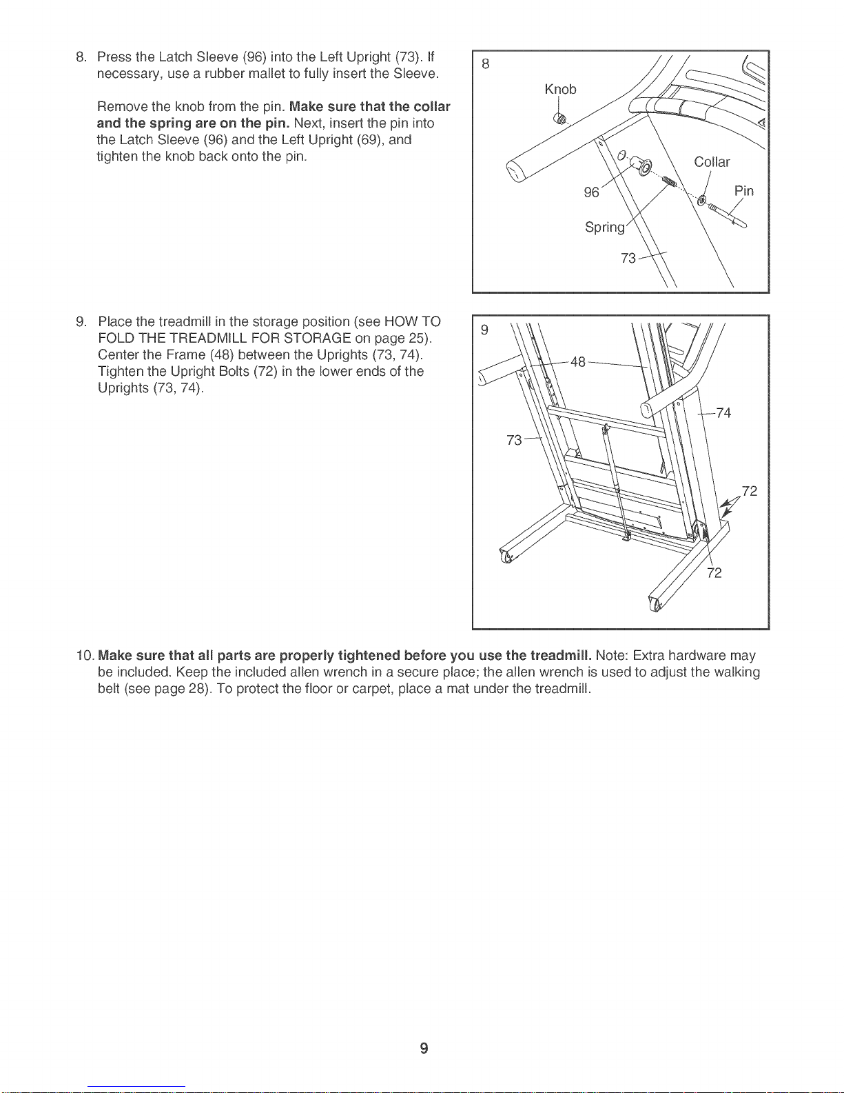
Press the Latch Sleeve (96) into the Left Upright (73). Rf
8. 8
necessary, use a rubber mallet to fully insert the Sleeve.
Remove the knob from the pin. Make sure that the collar
and the spring are on the pin. Next, insert the pin into
the Latch Sleeve (96) and the Left Upright (69), and
tighten the knob back onto the pin.
.
Place the treadmill in the storage position (see HOW TO
FOLD THE TREADMRLL FOR STORAGE on page 25).
Center the Frame (48) between the Uprights (73, 74).
Tighten the Upright Bolts (72) in the lower ends of the
Uprights (73, 74).
Knob
Collar
Spring _
73
73
72
10. Make sure that all parts are properly tightened before you use the treadmill. Note: Extra hardware may
be included. Keep the included allen wrench in a secure place; the allen wrench is used to adjust the walking
belt (see page 28). To protect the floor or carpet, place a mat under the treadmill.
9
Page 10
if you purchase the optional chest pulse sensor (see page 24), follow the steps below to install the re-
ceiver included with the chest pulse sensor.
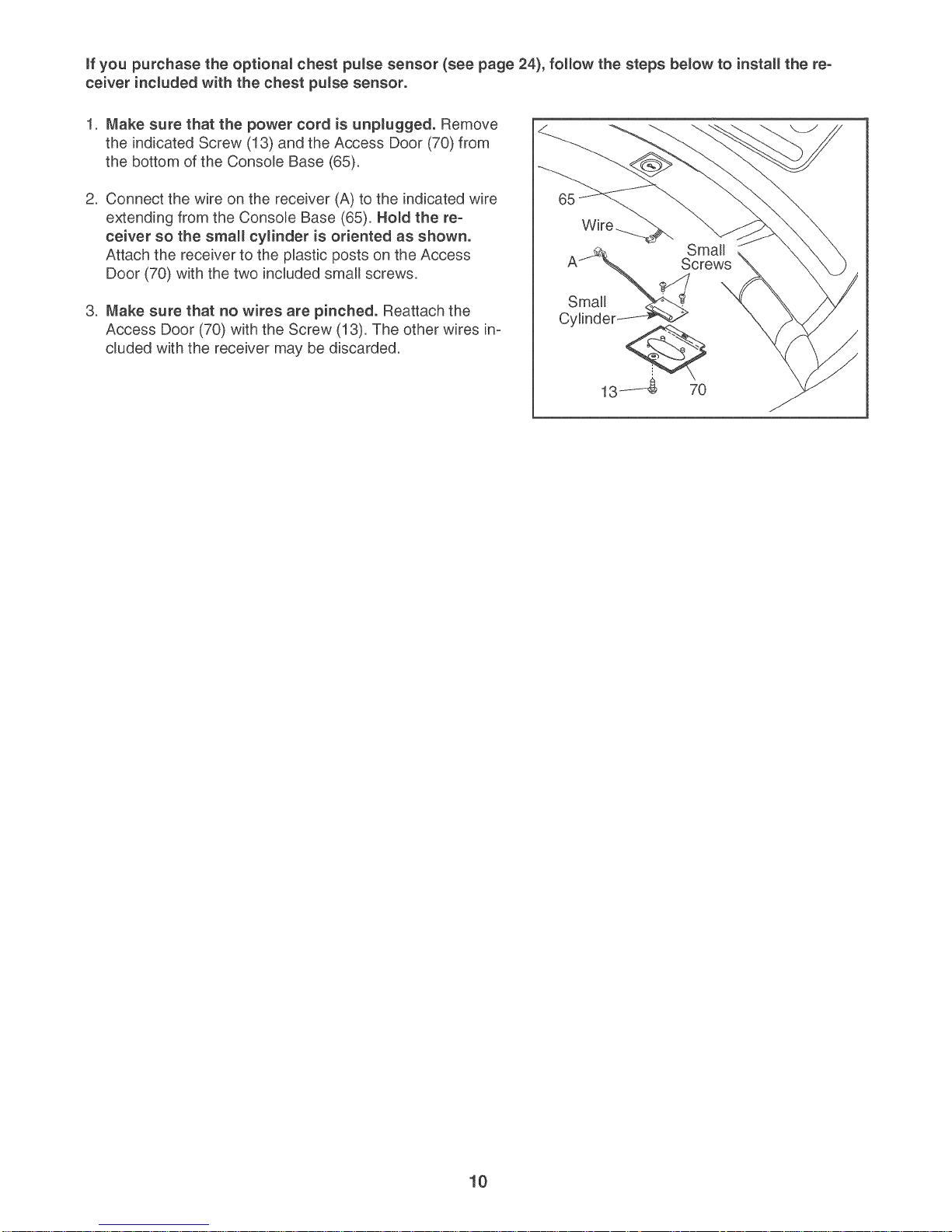
1. Make sure that the power cord is unpmugged. Remove
the indicated Screw (13) and the Access Door (70) from
the bottom of the Console Base (65).
2. Connect the wire on the receiver (A) to the indicated wire
extending from the Console Base (65), Hold the re-
ceiver so the small cylinder is oriented as shown.
Attach the receiver to the plastic posts on the Access
Door (70) with the two included small screws.
3. Make sure that no wires are pinched. Reattach the
Access Door (70) with the Screw (13). The other wires in-
Small
Cylinder
Screws
cluded with the receiver may be discarded.
13,_-$ 70
10
Page 11
TREADMmLL OPERATION
THE PRE-LUBRUCATED WALKUNG BELT
Your treadmill features a walking belt coated with high-
performance lubricant, iMPORTANT: Never apply siF
icone spray or other substances to the waIMng
be_t or the walking p_atform. Such substances will
deteriorate the walking be_t and cause excessive
wear.
HOW TO PLUG mNTHE POWER CORD
Your treadmill, like any other type of sophisticated
electronic equipment, can be seriously damaged by
sudden voltage changes in your home's power.
Voltage surges, spikes, and noise interference can
result from weather conditions or from other appliances
being turned on or off. To decrease the possibility of
your treadmill being damaged, a_ways use a surge
suppressor with your treadmill (see drawing 1 at
the right}. To purchase a surge suppressor, see
your _ocal NordicTrack dea_er or call the toll-free
telephone number on the front cover of this man-
ua_ and order part number 146148, or see your _oca_
e_ectronics store.
tric shock. This product is equipped with a cord having
an equipment-grounding conductor and a grounding
plug. P_ug the power cord into a surge suppressor,
and p_ug the surge suppressor into an appropriate
out_et that is proper_y installed and grounded in
accordance with aH _oca_codes and ordinances.
Important: The treadmill is not compatible with
GFCl-equipped outlets.
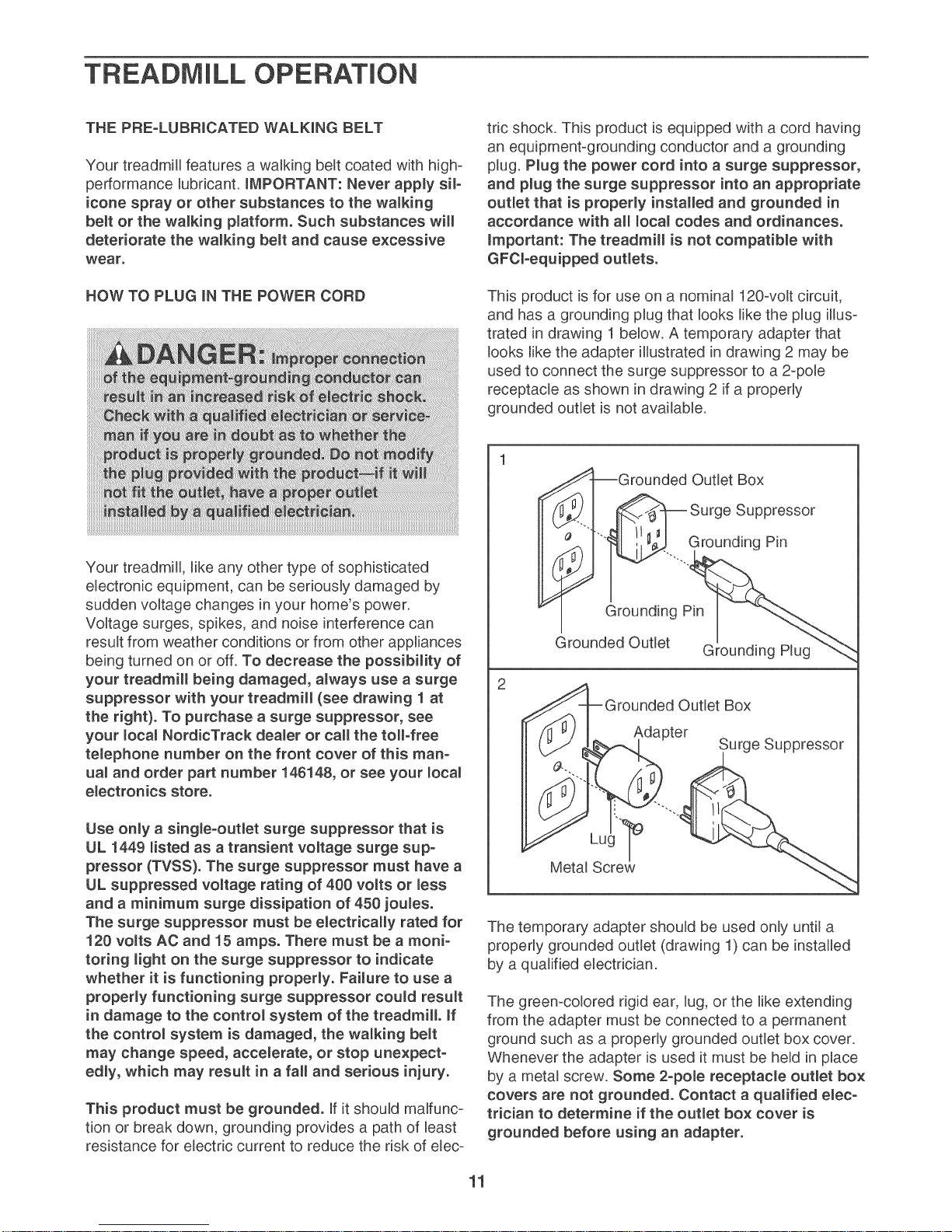
This product is for use on a nominal 120-volt circuit,
and has a grounding plug that looks like the plug illus-
trated in drawing 1 below. A temporary adapter that
looks like the adapter illustrated in drawing 2 may be
used to connect the surge suppressor to a 2-pole
receptacle as shown in drawing 2 if a properly
grounded outlet is not available.
Grounded Outlet Box
_--I _ Surge Suppressor
I
Grounding Pin
Grounded Outlet Grounding Plug
2
Outlet Box
Adapter
Surge Suppressor
Use only a sing_e-ouflet surge suppressor that is
UL 1449 _isted as a transient voRtage surge sup-
pressor (TVSS). The surge suppressor must have a
UL suppressed voltage rating of 400 vomts or _ess
and a minimum surge dissipation of 450 joules.
The surge suppressor must be e_ectrica_myrated for
120 volts AC and 15 amps. There must be a moni-
toring _ight on the surge suppressor to indicate
whether it is functioning properRy. Faimure to use a
proper_y functioning surge suppressor could result
in damage to the contro_ system of the treadmi& ff
the contro_ system is damaged, the walking be_t
may change speed, accemerate, or stop unexpect-
edly, which may result in a fall and serious injury.
This product must be grounded. If it should malfunc-
tion or break down, grounding provides a path of least
resistance for electric current to reduce the risk of elec-
The temporary adapter should be used only until a
properly grounded outlet (drawing 1) can be installed
by a qualified electrician.
The green-colored rigid ear, lug, or the like extending
from the adapter must be connected to a permanent
ground such as a properly grounded outlet box cover.
Whenever the adapter is used it must be held in place
by a metal screw. Some 2-poLe receptacle outlet box
covers are not grounded. Contact a qualified e_ec-
trician to determine if the outlet box cover is
grounded before using an adapter.
11
Page 12

FEATURES OF THE CONSOLE
The treadmill console offers an impressive array of
features designed to make your workouts more effec_
tive and enjoyable. When the manual mode of the con-
sole is selected, the speed and incline of the treadmill
can be changed with the touch of a button. As you ex-
ercise, the consob will display continuous exercise
feedback. You can even measure your heart rate using
the handgrip pulse sensor or the optional chest pulse
sensor (see page 24).
In addition, the console features twelve Cardio pro°
grams and three Calorie programs. Each program auto-
matically controls the speed and incline of the treadmill
as it guides you through an effective workout. You can
even create your own Record programs and save them
for future use. The console also offers four Pulse pro-
grams that control the speed and incline of the treadmill
to help you keep your heart rate near target heart rate
settings. Note: The Pulse programs require the use of
the optional chest pulse sensor.
The console also features the new iFIT SD system. The
iFIT SD system enables the console to accept iFIT
Cards containing workout programs designed to help
you achieve specific fitness goals. For example, lose
unwanted pounds with the 8-week Weight Loss pro-
gram, or train for a Iong-distance run with the
Marathon program, iFIT programs automatically control
the treadmill while the voice of a personal trainer
coaches you and motivates you through every step of
your workout. One iFIT Card with three new programs
is included. Additional iFIT Cards are available sepa_
rately. To purchase iFIT Cards at any time, go to
www.iFIT.com or call the toll-free telephone num-
ber on the front cover of this manual iFIT Cards
are a_so available at select stores.
To turn on the power, follow the steps on page 13. To
personalize console settings, see page 13. To use
the manua_ mode, see page 15. To use a Cardio pro-
gram, see page 17. To use a CaJorie program, see
page 18. To create and use a Record program, see
pages 19 and 20. To use a Pumseprogram, see page
21. To use an iFIT card, see page 23.
Note: If there is a sheet of clear plastic on the console,
peel off the clear plastic.
12
Page 13

HOW TO TURN ON THE POWER
Hug in the power cord
(see page 11). Next,
locate the reset/off cir-
cuit breaker on the
treadmill frame near
the power cord. Make
sure that the circuit
breaker is in the reset position.
Reset
Position
USER 1 SELECTED
TDTRL DI-EiTRHEE 51E I"IILE z;
TDTRL TIME 515 HDUR5
TDTRL ERLDRIE5 51H EHLDRIE5
USER I_IEIGHT IB5 PDUHb5
MAN HEART RHTE 11D gPh'l
When the Users button is pressed, the words
"User 1 Selected" or "User 2 Selected" will appear
in the display. To identify yourself as User 1 or
User 2, press the Users button once or twice.
Stand on the foot
rails of the tread-
mill. Find the clip
attached to the key,
and slide the clip
securely onto the
waistband of your
clothes. Next, in-
sert the key into the console. After a moment, the
display will light, important: in an emergency
situation, the key can be pulled from the con-
so_e, causing the wa_Mng be_t to s_ow to a
stop. Test the c_ip by carefully taking a few
steps backward; if the key is not pulled from
the console, adjust the position of the clip.
Note: To prevent damage to the walking platform,
wear clean athletic shoes while using the tread-
mill. The first time the treadmill is used, observe
the alignment of the walking belt, and center the
walking belt if necessary (see page 28).
HOW TO PERSONAUZE CONSOLE SETTINGS
The console features a users mode that allows you to
designate yourself as User 1 or User 2, view your
workout history, and enter user information before you
begin exercising.
The console also features a settings mode that allows
you to select a system of measurement for the con-
sole, turn on and turn off the demo mode, enter an
audio trainer setting, adjust the volume and contrast
settings of the console, and turn on and turn off the
welcome screen.
Follow the steps below to personalize console settings.
Select the users mode.
To select the users mode, press the Users button.
The console can keep track of workout history and
save information for two different users.
Important: To highlight options within the
menu, press the Data Entry increase and de-
crease buttons.
View your workout history.
The display will show the total number of miles or
kilometers that the walking belt has moved, the
total number of hours that the treadmill has been
used, and the total number of calories that the user
has burned.
To reset any of the totals, first highlight the total
that you want to reset and press the Enter button.
Then, highlight NO or YES and press the Enter
button.
Enter user information.
Highlight the words USER WEIGHT and then
press the Enter button. Next, press the Data Entry
increase and decrease buttons to enter your
weight. Then, press the Enter button.
If you want to enter a maximum target heart rate
(see HOW TO USE A PULSE PROGRAM on
page 21), first highlight MAX. HEART RATE and
press the Enter button. Next, press the Data Entry
increase and decrease buttons to enter a maximum
target heart rate. Then, press the Enter button.
To exit the users mode, highlight START and then
press the Enter button.
Select the settings mode.
To select the settings mode, first remove the key
from the console. Then, hold down the Stop but-
ton while reinserting the key into the console.
TDTRL TIIIE ESE TDTHL blSTRNEr' SIE
Iqt,]_ ENGLISH
bEHD HDGr, RDHb
HUblD TRHIHr,R IH5TF:Ur,TIDH
UDLUt"IE S
r,DHTRRST ID
13
Page 14

When the settings mode is selected, the display
will show the word ENGLISH or METRIC to indi-
cate which system of measurement is selected. To
change the system of measurement, first highlight
UNITS and press the Enter button. Next, press the
Data Entry increase or decrease button to select
the desired system of measurement. Then, press
the Enter button.
lected as your audio setting. If you select the "On"
setting, your personal trainer will simply guide you
through your iFIT workouts. If you select "Off," you
will hear no audio guidance during your workouts.
To change the audio setting, first highlight AUDIO
TRAINER and press the Enter button. Next, press
the Data Entry increase or decrease button to se-
lect the desired audio setting. Then, press the
Enter button.
TINE __SE TDTRLblSTRHEE 51;=
| bEND HDDE RDRD
| RUDIDTP,RIHER IHSTRDETIDI"I
| UDLUHE 5
EOHTRR5T 10
EI'.InLISH
The display will also show the words DEMO
MODE and the current setting: OFF, LOGO,
ROAD, or PROGRAMS. The "demo mode" can be
used while the treadmill is displayed in a store.
While the demo mode is selected, the power cord
can be plugged in, the key can be removed from
the console, and the display will remain on. The
console buttons will not function. To select a
demo mode, highlight DEMO MODE and then
press the Enter button. Next, press the Data Entry
increase or decrease button to highlight OFF (to
turn off the demo mode), LOGO (to display a logo),
ROAD (to display an animation of a runner on a
road), or PROGRAMS (to display previews of vari-
ous programs). Then, press the Enter button.
You can select an audio setting if desired. When
you use an iFIT Card, a personal trainer will guide
you through your workouts and instruct you how
to purchase more iFIT Cards if "Instruction" is se-
You can adjust the volume of your personal
trainer's voice by highlighting VOLUME, pressing
the Enter button, and then pressing the Data Entry
increase and decrease buttons to select a volume
setting. Then, press the Enter button.
The contrast of the display can also be adjusted.
To adjust the contrast of the display, first highlight
CONTRAST and press the Enter button. Next,
press the increase and decrease buttons to select
a contrast setting. Then, press the Enter button.
The console can also display a welcome message
each time you insert the key into the console.
Highlight WELCOME SCREEN and press the
Enter button. Then, press the Data Entry increase
or decrease button to select ON or OFF and press
the Enter button.
When you are finished using the settings
mode, remove the key.
To exit the settings mode at any time, remove the
key from the console.
14
Page 15

HOW TOUSE THE MANUAL MODE
Insert the key into the console.
See HOW TO TURN ON THE POWER on page
13.
Personalize console settings if desired.
Change the incline of the treadmill as desired.
To change the incline of the treadmill, press one
of the twelve Zip-Incline buttons. Each time one of
the buttons is pressed, the incline will gradually in-
crease until it reaches the selected incline setting.
SeRect a display mode and monitor your
progress with the display and the intensity
_eve_bar.
See HOW TO PERSONALIZE CONSOLE SET-
TINGS on page 13.
Select the manua_ mode.
Each time the key is inserted, the manual mode
will be selected. If you have selected a program,
press any of the program buttons repeatedly until
the word MANUAL appears in the display.
Start the walking be_t and adjust the speed.
To start the walking belt, press the Start button,
the Speed increase button next to the Start but-
ton, or one of the twelve Zip-Speed buttons.
If the Start button or the Speed increase button is
pressed, the walking belt will begin to move at 1
mph. As you exercise, change the speed of the
walking belt as desired by pressing the Speed in-
crease and decrease buttons next to the Start but-
ton. Each time a button is pressed, the speed set-
ting will change by 0.1 mph; if a button is held
down, the speed setting will change in increments
of 0.5 mph. If one of the twelve Zip-Speed buttons
is pressed, the walking belt will gradually increase
in speed until it reaches the selected speed set-
ting.
To stop the walking belt, press the Stop button. To
restart the walking belt, press the Start button, the
Speed increase button, or one of the twelve Zip-
Speed buttons.
As you walk or run on the treadmill, the display
can show the following workout information:
• The elapsed time.
The distance that you have walked or run.
The speed of the walking belt.
The incline level of the treadmill.
The approximate number of calories you have
burned.
The approximate number of grams of carbs
you have burned.
Your walking or running pace, in minutes per
mile or minutes per kilometer.
Your heart rate. Note: Your heart rate can be
displayed only while you use the handgrip
pulse sensor or the optional chest pulse
sensor.
In addition, the display can show a "workout
history"--a profile that represents the speed
settings that you select during your workout. At
the beginning of each minute of your workout,
an additional column will appear in the profile;
as you increase or decrease the speed setting,
the height of the column will increase or de-
crease.
The display can also show an animation of a
runner on a road. As you increase or decrease
the speed setting, the runner will speed up or
slow down.
15
Page 16

When the manual mode is selected, the console
offers eight display modes. The display mode that
you select will determine which workout informa_
tion is shown. For example, the first display mode
shows only the elapsed time and the distance that
you have walked or run. Press the Display button
repeatedly to select the desired display mode.
[]
Note: Regardless of which display mode you se-
lect, the speed or incline setting will appear in the
dispJay for a few seconds each time you change
the setting. Rnaddition, your heart rate will appear
in the display for up to 40 seconds each time you
use the handgrip pulse sensor or put on the op-
tional chest pulse sensor. Note: If you select the
display mode shown below, your heart rate will be
shown in place of the approximate number of
grams of carbs you have burned.
TIME DmSTHHEE
3Z:11
5PEE_) IHELIHE EnLDRIE_ EnR_5
12.0 18.7
the display will not show your heart rate accu_
rately.
To use the
handgrip
pulse sensor,
first remove
the sheets of
clear plastic Contacts
from the metal
contacts on
the handgrip
pulse sensor.
Next, stand on the foot rai_s and hold the metal
contacts--avoid moving your hands. When your
pulse is detected, your heart rate will appear in
the display. For the most accurate heart rate
reading, continue to ho_d the contacts for
about 15 seconds.
Turn on the fan if desired.
To turn on the fan at low speed, press the Fan
button. To turn on the fan at medium speed, press
the button a second time. To turn on the fan at
high speed, press the button a third time. To se-
lect the auto fan mode, press the button a fourth
time. When the auto fan mode is selected, the
speed of the fan will automatically increase or de-
crease as the speed of the walking belt increases
or decreases.
As you exercise, the intensity level bar will indicate
the approximate intensity level of your exercise.
For example, if eight of the indicators in the bar are
lit, the bar shows that your intensity level is ideal
for aerobic exercise.
To reset the console, press the Stop button, re-
move the key, and then reinsert the key.
Measure your heart rate if desired.
Note: If you use the handgrip pulse sensor and
the optional chest pulse sensor at the same time,
To turn off the fan, press the Fan button again.
Note: If the fan is on when the walking belt stops,
the fan will automatically turn off after a few min-
utes.
When you are finished exercising, remove the
key.
Step onto the foot rails, press the Stop button, and
adjust the incline of the treadmill to the lowest set-
ting. The incline must be at the _owest setting
when the treadmill is fo_ded to the storage posi-
tion or the treadmill will become damaged. Next,
remove the key from the console and put it in a se-
cure place.
When you are finished using the treadmill,
switch the reset/off circuit breaker to the "off"
position and unplug the power cord.
16
Page 17

HOW TO USE A CARDIO PROGRAM
Insert the key into the console.
See HOW TO TURN ON THE POWER on page
13.
Personalize console settings if desired.
See HOW TO PERSONALIZE CONSOLE SET-
TINGS on page 13.
Select a Cardio program.
To select a Cardio program, press the Cardio but-
ton repeatedly.
ff the first or second display mode is selected, a
profile of the speed settings of the program will ap-
pear in the display. A small arrow below the profile
will indicate your progress.
At the end of the first one-minute segment of the
program, a series of tones will sound. If a different
speed setting and/or incline setting is pro-
grammed for the second segment, the speed set-
ring and/or incline setting will appear at the top of
the display for a moment to alert you. The tread-
mill will then automatically adjust to the speed and
incline settings for the second segment.
The program will continue in this way until the
small arrow reaches the right end of the profile.
The walking belt will then slow to a stop.
When a Cardio program is selected, the display
will show the name of the program, the maximum
incfine setting of the program, and the maximum
speed setting. In addition, a profile of the speed
settings of the program will appear in the display.
Each preset program is divided into 30 one-
minute segments. One speed setting and one in-
cline setting are programmed for each segment.
Note: The same speed setting and/or incline set-
ring may be programmed for two or more consec-
utive segments.
Press the Start button to start the program.
A moment after the button is pressed, the tread-
mill wifl automatically adjust to the first speed and
incline settings of the program. Hold the handrails
and begin walking.
Select a display mode and monitor your
progress with the display.
When a Cardio program is selected, the console
offers three display modes. Press the Display but-
ton repeatedly to select the desired display mode.
ff the third display mode is selected, the display
will show an animation of a runner.
At the end of the first one-minute segment of the
program, a series of tones will sound. If a different
speed setting is programmed for the second seg-
ment, the speed setting will move along the bot-
tom of the display to alert you. If a different incline
setting is programmed, the incline setting will ap-
pear at the top of the display for a moment. The
treadmill will then automatically adjust to the
speed and incline settings for the second seg-
ment.
The program will continue in this way until the last
segment ends. The walking belt will then slow to a
stop.
17
Page 18

If the speed or incline setting for the current seg-
ment is too high or too low, you can override the
setting by pressing the Speed or Incline buttons;
however, when the next segment begins, the
treadmill will automatically adjust to the speed
and incline settings for the next segment.
2
HRX IHr'LIHE ln.O_ HRX 5PEEB "1.5 I'.IPH
To stop the program at any time, press the Stop
button. To restart the program, press the Start but=
ton. The walking belt will begin to move at 1 mph.
When the next segment of the program begins, the
treadmill will automatically adjust to the speed and
incline settings for the next segment.
Measure your heart rate if desired.
See step 7 on page 16.
Turn on the fan if desired.
See step 8 on page 16.
When you are finished exercising, remove the
key from the console.
When the program ends, make sure that the in-
cline of the treadmimmis at the _owest setting.
Next, remove the key from the console and put it in
a secure place.
When you are finished using the treadmill,
switch the reset!off circuit breaker to the "off"
position and unplug the power cord.
HOW TO USE A CALORIE PROGRAM
Insert the key into the console.
See HOW TO TURN ON THE POWER on page
13.
When a Calorie program is selected, the display
will show the name of the program, the number of
minutes in the program, the calorie goal (the num=
ber of calories to be burned during the program),
the maximum incline setting of the program, and
the maximum speed setting. In addition, a profile
of the speed settings of the program will appear in
the display.
Press the Start button to start the program.
A moment after the button is pressed, the walking
belt will begin to move at 3 mph. Hold the
handrails and begin walking.
If the speed or incline setting for the current seg-
ment is too high or too low, you can override the
setting by pressing the Speed or Incline buttons;
however, when the next segment begins, the
treadmill will automatically adjust to the speed
and incline settings for the next segment.
Select a display mode and follow your
progress with the display.
The Calorie program will function in the same way
as a Cardio program (see step 5 on page 17), ex=
cept that while you exercise, the display will show
the number of calories still to be burned.
The program will end when you reach your calorie
goal or when the small arrow reaches the right
end of the profile, whichever occurs first. The
walking belt will then slow to a stop.
Measure your heart rate if desired.
Personalize console settings if desired.
See HOW TO PERSONALIZE CONSOLE SET=
TINGS on page 13. Note: You must enter your
weight (see step 3 on page 13) for the console to
most accurately calculate the number of calories to
be burned during your workout.
Select a Calorie program.
To select a Calorie program, press the Calorie
button one, two, or three times.
See step 7 on page 16.
Turn on the fan if desired.
See step 8 on page 16.
When you are finished exercising, remove the
key from the console.
See step 8 at the left.
18
Page 19

HOW TO CREATE A RECORD PROGRAM
Select a display mode and program the
desired speed and incline settings.
insert the key into the console.
See HOW TO TURN ON THE POWER on page
13.
Personalize console settings if desired.
See HOW TO PERSONAUZE CONSOLE SET-
TRNGSon page 13.
Select a Record program.
To select a Record program, press the Record
button once or twice.
RECORD N..,.Eu.E ... 5PEE"I
PROORRH o=_ 2.sMP./
1 •
PRDSRRPI TIPIE 3:rid j
if the Record program has not yet been de-
fined, the display will show a program time of
three minutes, if the program time is more than
three minutes, see HOW TO USE A RECORD
PROGRAM on page 20.
When a Record program is selected, the console
offers three display modes. Press the Display but-
ton repeatedly to select the desired display mode.
To program a speed setting and an incline setting
for the first one-minute segment of the program,
simply adjust the speed and incline of the treadmill
as desired by pressing the Speed and Incline but-
tons.
When the first segment ends, a series of tones will
sound and the current speed setting and the cur=
rent incline setting will be saved in memory.
Program a speed setting and an incline setting for
the second segment as described above. Continue
programming speed and incline settings for up to
30 segments.
When you are finished with your workout, press
the Stop button twice. The Record program will
then be saved in memory.
When you are finished exercising, remove the
key from the console.
See step 8 on page 18.
Each Record program is divided into one-minute
segments. One speed setting and one incline set-
ring can be programmed for each segment.
Press the Start button to start the program.
A moment after the button is pressed, the walking
belt will begin to move. Hold the handrails and
begin walking.
19
Page 20

HOW TO USE A RECORD PROGRAM
incline settings that you programmed previously.
Hold the handrails and begin walking.
Insert the key into the console.
See HOW TO TURN ON THE POWER on page
13.
Personalize console settings if desired.
See HOW TO PERSONALIZE CONSOLE SET=
TINGS on page 13.
Select a Record program.
To select a Record program, press the Record
button once or twice.
RECORD
PROGRRH
1
When a Record program is selected, the display
will show the name of the program, the maximum
incfine setting of the program, and the maximum
speed setting. In addition, a profile of the speed
settings of the program will appear in the display.
Note: If the display shows a program time of
three minutes, see HOW TO CREATE A
RECORD PROGRAM on page 19.
Select a display mode and monitor your
progress with the display.
The Record program will function in the same way
as a Cardio program (see step 5 on page 17).
If desired, you can redefine the program while
using it. To change the speed or incline setting
for the current segment, simply press the Speed
or Incline buttons. When the current segment ends,
the new setting will be saved in memory. To in-
crease the length of the program, first wait until
the program ends. Then, press the Start button and
program speed and incline settings for as many ad-
ditional segments as desired; Record programs can
have up to 30 segments. When you have added as
many segments as desired, press the Stop button
twice. To decrease the length of the program,
press the Stop button twice at any time before the
program ends.
Measure your heart rate if desired.
See step 7 on page 16.
Turn on the fan if desired.
See step 8 on page 16.
When you are finished exercising, remove the
key from the console.
Each Record program is divided into one=minute
segments. One speed setting and one incline set-
ring are programmed for each segment.
Press the Start button to start the program.
A moment after the button is pressed, the tread-
mill will automatically adjust to the first speed and
See step 8 on page 18.
2O
Page 21

HOW TO USE A PULSE PROGRAM
may be programmed for two or more consecutive
segments.
Adjust the maximum target heart rate setting if
desired.
To adjust the maximum target heart rate setting,
press the Data Entry increase and decrease but-
tons beside the Enter button (see EXERCISE IN=
TENSITY on page 29). To adjust the target heart
rate setting quickly, hold down one of the buttons.
Follow the steps below to use a Pulse program.
Put on the optiona_ chest pu_se sensor.
Note: You must wear the optional chest pulse sen=
sor to use a Pulse program.
insert the key into the console.
See HOW TO TURN ON THE POWER on page
13.
Personalize console settings if desired.
See HOW TO PERSONALIZE CONSOLE SET=
TINGS on page 13.
Select a Pu_se program.
To select a Pulse program, press the Cardio but-
ton repeatedly until you reach the Pulse pro-
grams.
PULSE .A. TAR_.ET.E.RTRATE
PROGRRH el IIJI,JIIJIJIJk
11U
4
RBJU5T TARGET WITH UP DR BDL,,IH EUTTDt45
When a Pulse program is selected, the display will
show the name of the program and the maximum
target heart rate setting of the program. In addi-
tion, a profile of the target heart rate settings of
the program will appear in the display.
Pulse program 1 is divided into one-minute seg=
merits. The same target heart rate setting is pro=
grammed for all segments (except for the first two
segments). Pulse programs 2, 3, and 4 are di-
vided into 30 one-minute segments. One target
heart rate setting is programmed for each seg-
ment. Note: The same target heart rate setting
Press the Start button to start the program.
A moment after the button is pressed, the walking
belt will begin to move. Hold the handrails and
begin walking.
Select a display mode and monitor your
progress with the display.
When a Pulse program is selected, the console of=
fers two display modes. Press the Display button
to select the desired display mode.
Regardless of which display mode you select, a
profile of the target heart rate settings of the pro-
gram will appear in the display. A white line repre=
senting your heartbeat will also appear; each time a
heartbeat is detected, an additional peak will ap-
pear in the line. A small arrow below the profile will
indicate your progress.
During each one-minute segment of the program,
the console will compare your heart rate to the
current target heart rate setting. If your heart rate
is too far below or above the target heart rate set-
ring, the speed of the walking belt or the incline of
the treadmill will automatically change to bring
your heart rate closer to the target heart rate set-
ting. Each time the speed or incline changes, the
speed setting and the incline setting will appear at
the top of the display for a moment to alert you.
When each segment ends, a series of tones will
sound.
21
Page 22

Rfthe speed or incline setting for the current seg-
ment is too high or too low, you can override the
setting by pressing the Speed or Rnclinebuttons;
however, when the console compares your heart
rate to the current target heart rate setting, the
speed or incline of the treadmill may automatically
change.
To stop the program at any time, press the Stop
button. To restart the program, press the Start but-
ton. The walking belt will begin to move at 1 mph.
When the console compares your heart rate to the
current target heart rate setting, the speed or in-
cline of the treadmill may automatically change.
RfPulse program 1 is selected, the program will
continue until you stop it by pressing the Stop but-
ton. RfPulse program 2, 3, or 4 is selected, the
program will continue until the small arrow
reaches the right end of the profile. The walking
belt will then slow to a stop.
Turn on the fan if desired.
See step 8 on page 16.
When you are finished exercising, remove the
key from the console.
See step 8 on page 18.
22
Page 23

HOW TO USE AN IFIT CARD
insert the key into the console.
See HOW TO TURN ON THE POWER on page
13.
Personalize console settings if desired.
See HOW TO PERSONALIZE CONSOLE SET-
TINGS on page 13.
insert an iFIT Card and select a program.
To use an iFIT program, insert an iFIT Card into
the iFIT slot; make sure that the iFIT Card is ori-
ented so the metal contacts are on top and are in-
serted into the iFIT slot.
Press the Start button to start the program.
A moment after the button is pressed, the tread-
mill will automatically adjust to the first speed and
incline settings of the program. Hold the handrails
and begin walking.
SeRect a display mode and monitor your
progress with the display and the intensity
_eve_bar.
When an iFIT program is selected, the console of-
fers three display modes (see step 6 on page 15).
Press the Display button repeatedly to select the
desired display mode. ff the first or second dis-
pmaymode is semected, a profile of the speed set-
tings of the program will appear in the display. A
small arrow below the profile will indicate your
progress.
During the program, a personal trainer will guide
you through the workout. You can adjust the voF
ume or select an audio setting for your personal
trainer (see step 4 on pages 13 and 14).
Next, select an iFIT program by pressing the
Cardio, Record, or Calorie button repeatedly.
When an iFIT program is selected, the display will
show the name of the program, the maximum in-
cline setting and the maximum speed setting of
the program, and the program time. In addition, a
profile of the speed settings of the program will
appear in the display.
Each preset program is divided into several one-
minute segments. One speed setting and one in-
cline setting are programmed for each segment.
Note: The same speed setting and/or incline set-
ring may be programmed for two or more consec-
utive segments.
If the speed or incline setting for the current seg-
ment is too high or too low, you can override the
setting by pressing the Speed or Incline buttons;
however, when the next segment begins, the
treadmill will automatically adjust to the speed
and incline settings for the next segment.
To stop the program at any time, press the Stop
button. To restart the program, press the Start but-
ton. The walking belt will begin to move at 1 mph.
When the next segment of the program begins, the
treadmill will automatically adjust to the speed and
incline settings for the next segment.
Turn on the fan if desired.
See step 8 on page 16.
When you are finished exercising, remove the
key from the console.
See step 8 on page 18.
CAUTION: Always remove iFIT Cards from the
iFIT s_ot when you are not using them.
23
Page 24

HOW TO ADJUST THE CUSHUONING SYSTEM THE OPTIONAL CHEST PULSE SENSOR
The treadmill features a cushioning system that re-
duces the impact as you walk or run on the treadmill.
To increase the firmness of the walking platform, step
off the treadmill and slide the cushion adjusters toward
the front of the treadmill. To decrease the firmness,
slide the cushion adjusters toward the back of the
treadmill. Note: Make sure that both adjusters are
set at the same firmness _eveL The faster you run
on the treadmill, or the more you weigh, the firmer
the walking p_atform should be.
\
Cushion
Adjustor
Cushion
Adjustor
g Platform
An optional chest pulse sensor adds even more fea-
tures to the console. The chest pulse sensor offers
hands-free operation, and enables you to use the
Pulse programs. To purchase the optiona_ chest
pu_se sensor, call the to_Ffree telephone number
on the front cover of this manual
24
Page 25

HOW TO FOLD AND MOVE THE TREADMmLL
HOW TO FOLD THE TREADMILL FOR STORAGE
Before fo_ding the treadmill, adjust the incline to the
_owest position, ff this is not done, the treadmill may be
permanently damaged. Next, unplug the power cord.
CAUTION: You must be able to safe_y _ift 45 pounds (20
kg) to raise, _ower, or move the treadmill.
1. Hold the end of the treadmill near the location indicated by
the arrow at the right. To decrease the possibility of in-
jury, bend your _egs and keep your back straight. As
you raise the frame, make sure to lift with your _egs
rather than your back. Raise the frame about halfway to
the vertical position.
2. Move your right hand to the position shown and hold the
treadmill firmly. Using your left hand, pull the latch knob
to the left and hold it. Raise the treadmill until the catch is
aligned with the latch pin. Slowly release the latch knob.
Make sure that the _atch pin is fully inserted into the
catch.
To protect the floor or carpet from damage, p_ace a
mat under the treadmill. Keep the treadmill out of
direct sunlight. Do not meavethe treadmill in the stor-
age position in temperatures above 85° Fahrenheit..
HOW TO MOVE THE TREADMILL
Before moving the treadmill, convert the treadmill to the
storage position as described above. Make sure that the
_atch pin is fully inserted into the catch.
1. Hold the treadmill and place one foot against one of the
wheels.
2. Tilt the treadmill back until it roils on the wheels. Carefully
move the treadmill to the desired location. To reduce the
risk of injury, use e×treme caution whi_e moving the
treadmill. Do not attempt to move the treadmill over
an uneven surface.
3. Place one foot against one of the wheels, and carefully
lower the treadmill until the base is in the storage position.
Latch
Whee
Base
25
Page 26

HOW TO LOWER THE TREADMILL FOR USE
.
Hold the upper end of the treadmill with your right hand
as shown. Using your left hand, pull the latch knob to the
left and hold it. Pivot the frame down until it is past the
latch pin. Then, slowly release the latch knob.
2. Hold the frame firmly with both hands, and lower it to the
floor. To decrease the possibility of injury, bend your
_egs and keep your back straight.
Latch
Knob Open
26
Page 27

TROUBLESHOOTING
Most treadmill probIems can be soIved by following the steps beIow. Find the symptom that applies, and
follow the steps _isted. if further assistance is needed, p_ease see the front cover of this manual
PROBLEM: The power does not turn on
SOLUTION: a.
PROBLEM: The power turns off during use
SOLUTION: a. Check the reset/off circuit breaker (see 1. c. above). If the circuit breaker has tripped, wait for five
PROBLEM: The displays of the console do not function properly
Make sure that the power cord is plugged into a surge suppressor, and that the surge suppressor
is plugged into a properly grounded outlet (see page 11). Use only a single-outlet surge suppres_
sot that meets all of the specifications described on page 11. Rmportant: The treadmill is not com-
pafible with GFCR-equipped outlets.
b. Make sure that the key is inserted into the console.
Check the reset/off circuit breaker located on the frame near the
C.
power cord. If the switch protrudes as shown, the circuit breaker has
tripped. To reset the circuit breaker, wait for five minutes and then
press the switch back in.
Off Reset
minutes and then press the switch back in.
b. Make sure that the power cord is plugged in. If the power cord is plugged in, unplug it, wait for
five minutes, and then plug it back in.
c. Remove the key from the console and then reinsert it.
SOLUTION: a. Remove the key from the console and UNPLUG THE POWER CORD. Place the treadmill in the
storage position (see HOW TO FOLD AND MOVE THE TREADMILL on page 25).
Next, remove the two indicated 3/'4" Screws (4).
4
Lower the treadmill (see HOW TO LOWER THE TREAD-
MILL FOR USE on page 26). Remove the four indicated
3/4" Screws (4), and remove the Hood (44).
27
Page 28

Next, locate the Reed Switch (14) and the Magnet (12) on
the left side of the Pulley (11). Turn the Pulley until the
Magnet is aligned with the Reed Switch. Make sure that
the gap between the Magnet and the Reed Switch is
about 1/8"o ff necessary, loosen the indicated Screw (29),
move the Reed Switch slightly, and then retighten the
Screw. Reattach the hood and run the treadmill for a few
minutes to check for a correct speed reading.
View
Top 14_
_-11
"12
PROBLEM:
The walking be_t s_ows when walked on
SOLUTION: a. Use only a single-outlet surge suppressor that meets all of the specifications described on page 11.
b.
Rfthe walking belt is overtightened, treadmill perfor-
mance may decrease and the walking belt may be
permanently damaged. Remove the key and UN-
PLUG THE POWER CORD. Using the included allen
wrench, turn both rear roller adjustment bolts counter-
clockwise 1/4 of a turn. When the walking belt is prop-
erly tightened, you should be able to lift each edge of
the walking belt 3 to 4 inches off the walking platform.
Be careful to keep the walking belt centered. Then,
plug in the power cord, insert the key, and run the
Rear Roller Bolts
treadmill for a few minutes. Repeat until the walking
belt is properly tightened.
c. If the walking belt still slows when walked on, please see the front cover of this manual.
PROBLEM: The walking belt is off-center or slips when walked on
SOLUTION: a.
If the walking belt is off-center, first remove the key
and UNPLUG THE POWER CORD. ff the waRking
berethas shifted to the left, use the allen wrench to
turn the left rear roller bolt clockwise 1/2 of a turn; if
the walking berethas shifted to the right, turn the
bolt counterclockwise 1/2 of a turn. Be careful not to
overtighten the walking belt. Then, plug in the power
cord, insert the key, and run the treadmill for a few
minutes. Repeat until the walking belt is centered.
b.
If the walking belt slips when walked on, first remove
the key and UNPLUG THE POWER CORD. Using
the allen wrench, turn both rear roller bolts clockwise
1/4 of a turn. When the walking belt is correctly tight-
ened, you should be able to lift each edge of the
walking belt 3 to 4 inches off the walking platform. Be
careful to keep the walking belt centered. Then, plug
in the power cord, insert the key, and walk on the
treadmill for a few minutes. Repeat until the walking
belt is properly tightened.
28
Page 29

EXERCISE GUiDELiNES
The following guidelines will help you to plan your ex-
ercise program. For more detailed exercise informa-
tion, obtain a reputable book or consult your physician.
EXERCISE INTENSITY
begin to use stored f3tc,_/oriesfor energy. If your goal
is to burn fat, adjust the speed or incline of the tread-
mill until your heart rate is near the lowest number in
your training zone.
For maximum fat burning, adjust the speed or incline
of the treadmill until your heart rate is near the middle
number in your training zone.
Aerobic Exercise
If your goal is to strengthen your cardiovascular sys-
tem, your exercise must be "aerobic." Aerobic exercise
is activity that requires large amounts of oxygen for
prolonged periods of time. This increases the demand
on the heart to pump blood to the muscles, and on the
lungs to oxygenate the blood. For aerobic exercise,
adjust the speed or incline of the treadmill until your
heart rate is near the highest number in your training
zone.
Whether your goal is to burn fat or to strengthen your
cardiovascular system, the key to achieving the
desired results is to exercise with the proper intensity.
The proper intensity level can be found by using your
heart rate as a guide. The chart below shows recom-
mended heart rates for fat burning and aerobic exercise.
HEART RATE TRAmNING ZONES
AEROBBC 165 155 145 140 130 125 115
MAX FAT BURN 145 138 130 125 118 110 103
FAT BURN 125 120 115 110 105 95 90
Age 20 30 40 50 60 70 80
To find the proper heart rate for you, first find your age
near the bottom of the chart (ages are rounded off to
the nearest ten years). Next, find the three numbers
above your age. The three numbers define your "train-
ing zone." The lower two numbers are recommended
heart rates for fat burning; the highest number is the
recommended heart rate for aerobic exercise.
Fat Burning
To burn fat effectively, you must exercise at a relatively
low intensity level for a sustained period of time.
Dunng the first few minutes of exercise, your body
uses easily accessible carbohydrate ca/cries for en-
ergy. Only after the first few minutes does your body
WORKOUT GUIDELINES
Each workout should include the following three parts:
A Warm-up--Start each workout with 5 to 10 minutes
of stretching and light exercise. A proper warm-up in-
creases your body temperature, heart rate and circula-
tion in preparation for exercise.
Training Zone Exercise--After warming up, increase
the intensity of your exercise until your pulse is in your
training zone for 20 to 60 minutes. (During the first few
weeks of your exercise program, do not keep your
pulse in your training zone for longer than 20 minutes.)
Breathe regularly and deeply as you exercise--never
hold your breath.
A CooFdown--Finish each workout with 5 to 10 min-
utes of stretching to cool down. This will increase the
flexibility of your muscles and will help prevent post-ex-
ercise problems.
EXERCISE FREQUENCY
To maintain or improve your condition, complete three
workouts each week, with at least one day of rest be-
tween workouts. After a few months, you may com-
plete up to five workouts each week if desired. The key
to success is to make exercise a regular and enjoyable
part of your everyday life.
29
Page 30

PART LiST--Model No. NTL16905.0 R0406A
To locate the parts listed below, see the EXPLODED DRAWING attached
Key No. Qty. Description Key No. Qty.
1 2 Foot Rail Cover 50 1
2 2 Foot Rail 51 1
3 2 Platform CusNon 52 4
4 33 3/4" Screw 53 2
5 1 Catch 54 1
6 1 Walking Platform 55 6
7 2 Belt Guide 56 2
8 4 Belt Guide Screw 57 1
9 2 Front Isolator 58 1
10 2 Platform Bolt, Front 59 1
11 1 Front Roller/Pulley 60 1
12 1 Magnet 61 2
13 24 1/2" Screw 62 2
14 1 Reed Switch Clip 63 1
15 1 Left Incline Rod BusNng 64 6
16 2 Lift Arm 65 1
17 2 Lift Pivot Bolt 66 1
18 2 Hood Mount 67 1
19 2 Lift Arm Spacer 68 1
20 1 Reed Switch 69 6
21 1 Idler Wheel Nut 70 1
22 1 Idler Wheel 71 6
23 1 Idler Wheel Bolt 72 6
24 1 Lift Motor Bolt, Bottom 73 1
25 1 Idler Arm Spacer 74 1
26 1 Idler Arm 75 1
27 1 Idler Arm Spring 76 6
28 1 Motor Belt 77 4
29 3 Reed Switch Screw 78 6
30 2 Lift Pivot Bolt 79 2
31 1 Drive Motor 80 2
32 2 Motor Bolt 81 4
33 4 Electronic Bracket Nut 82 4
34 1 Electronic Bracket 83 1
35 1 Front Endcap 84 1
36 1 Controller 85 2
37 1 Incline Rod 86 2
38 10 Nut 87 3
39 1 Lift Motor 88 1
40 1 Lift Motor Bolt, Top 89 1
41 2 Lift Motor Spacer 90 6
42 2 Cushion Adjustor 91 1
43 1 Power Cord Assembly 92 1
44 1 Hood 93 1
45 4 Hood Clip 94 2
46 1 Grommet 95 2
47 1 Walking Belt 96 1
48 1 Frame 97 1
49 16 Cushion Track Screw 98 1
in the center of this manual.
Description
Transformer
Right Rear Foot
Rear Wheel
Rear Wheel Bolt
Right Rear Endcap
Rear Roller Washer/Bracket Washer
Rear Roller Adj. Bolt
Allen Wrench
Left Rear Foot
Left Rear Endcap
Rear Roller
Platform Nut
Platform Bolt, Rear
Hood Cover
Handrail Bolt
Console Base
Console
Console Fan Grill
Static Decal
Electronics Screw
Access Door
Upright Star Washer
Upright Bolt
Left Upright
Right Upright
Upright Wire
Cage Nut
Base Pad Spacer
Washer
Endcap Screw
Base Endcap
Base Pad
1" Tek Screw
Base
Frame Ground Wire
Wheel Bolt
Wheel
Warning Decal
Shock
Key/Clip
Handrail Star Washer
Releasable Tie
Tie Clamp
Plastic Tie
Handrail Endcap
Handrail Spacer
Latch Sleeve
Top Handrail Endcap
Ground Nut
30
Page 31

Key No. Qty. Description Key No. Qty. Description
99 1 Handrail 107 1 Rncline Stop Bracket
100 1 Latch Assembly 108 1 Stop Bracket Spacer
101 1 Latch Warning Decal 109 2 Plastic Tie
102 2 Shock Pin # 2 7" Green Wire, M/Ring
103 1 Filter Wire # 1 6" Blue Wire, 2 F
104 1 Lift Motor Bolt # 1 User's Manual
105 1 Right Incline Rod Bushing
106 1 Rncline/Controller Wire #These parts are not illustrated
HOW TO ORDER REPLACEMENT PARTS
To order replacement parts, see the front cover of this manual. When ordering parts, please be prepared to give
the following information:
the MODEL NUMBER OF THE PRODUCT (NTL16905.0)
the NAME OF THE PRODUCT (NordicTrack EUTE 2900 treadmill)
the SERRAL NUMBER OF THE PRODUCT (see the front cover of this manual)
the KEY NUMBER AND DESCRPTION OF THE PART(S) (see the PART UST on pages 30 and 31 and the
EXPLODED DRAWING attached in the center of this manual)
31
Page 32

EXPLODED DRAWING--Model No. NTL16905.0 R0406A
57
L/
x/
49
49
101
62
56
3 4
61 _ 60
52
56
54
49
49
47
49
49
2O
I 1
13
31
I
33
33
39
38 I
4O
38
:: 108
103
/
/
/
/
Page 33

EXPLODED DRAWING--Model No. NTL16905.0 R0406A
894
94
94
66
13 13
67
13
13
95
64
90
64
9O
IO0
64
76
95
9O
87
87
83
64
._76
72
78
Page 34

LIMmTEDWARRANTY
WHAT IS COVERED--The entire NordicTrack ELITE 2900 treadmill ("Product") is warranted to be free of all defects in
matedal and workmanship.
WHO IS COVERED--The original purchaser or any person receiving the Product as a gift from the odginal purchaser.
HOW LONG IS IT COVERED--ICON Health & Fitness, Inc. ("ICON"), warrants the drive motor for life. Parts and labor
are warranted for one year from the date of purchase.
WHAT WE DO TO CORRECT COVERED DEFECTS--We will ship to you, without charge, any replacement part or
component, providing the repairs are authorized by ICON first and are performed by an ICON trained and authorized
service provider, or, at our option, we will replace the Product.
WHAT IS NOT COVERED--Any failures or damage caused by unauthorized service, misuse, accident, negligence, im-
proper assembly or installation, alterations, modifications without our written authorization or by failure on your part to
use, operate, and maintain as set out in your User's Manual ("Manual'). This warranty does not extend to products used
for commercial or rental purposes.
WHAT YOU MUST DO--Always retain proof of purchase, such as your bill of sale; store, operate, and maintain the
Product as specified in the Manual; notify our Customer Service Department of any defect within 10 days after discov-
ery of the defect; as instructed, return any defected part for replacement or, if necessary, the entire product, for repair.
USER'S MANUAL--It is VERY IMPORTANT THAT YOU READ THE MANUAL before operating the Product.
Remember to do the periodic maintenance requirements specified in the Manual to assure proper operation and your
continued satisfaction.
HOW TO GET PARTS AND SERVICE--Simply call our Customer Service Department at 1-888-825-2588 and tell them
your name and address and the serial number of your Product. They will tell you how to get a part replaced, or if neces-
sary, arrange for service where your Product is located or advise you how to ship the Product for service. Before ship-
ping, always obtain a Return Authorization Number (RA No.) from our Customer Service Department; securely pack
your Product (save the original shipping carton if possible); put the RA No. on the outside of the carton and insure the
product. Include a letter explaining the product or problem and a copy of your proof of purchase if you believe the ser-
vice is covered by warranty.
ICON is not responsible or liable for indirect, special or consequential damages arising out of or in connection with the
use or performance of the product or damages with respect to any economic loss, loss of property, loss of revenues or
profits, loss of enjoyment or use, costs of removal, installation or other consequential damages of whatsoever nature.
Some states do not allow the exclusion or limitation of incidental or consequential damages. Accordingly, the above lim-
itation may not apply to you.
The warranty extended hereunder is in lieu of any and all other warranties and any implied warranties of merchantability
or fitness for a particular purpose is limited in its scope and duration to the terms set forth herein. Some states do not
allow limitations on how long an implied warranty lasts. Accordingly, the above limitation may not apply to you.
No one is authorized to change, modify or extend the terms of this limited warranty.
This warranty gives you specific legal rights and you may have other rights which vary from state to state.
iCON HEALTH & FITNESS, iNC., 1500 S. 1000 W., LOGAN, UT 84321-9813
Part No. 233943 R0406A Printed in USA @ 2006 ICON IP, Inc.
 Loading...