

ModeJNo.NTEX4196.0
SerialNo.
SerialNumber
Decal
QUESTmONS?
As a manufacturer, we are com-
mitted to providing complete
customer satisfaction, if you
have questions, or if parts are
damaged or missing, PLEASE
CONTACT OUR CUSTOMER
SERVICE DEPARTMENT
DIRECTLY,
CALL TOLL-FREE:
1°888°825°2588
Mon.=Fri., 6 a.m.=6 p.m. MST
ER'S
ON THE WEB:
www.nordictrackservice.com
Read all precautions and instruc-
tions in this manual before using
this equipment. Keep this manuaJ
for future reference,
_our website a_-
www.nordictrack.com
new products, prizes,
fitness tips, and much more!
TABLE OF CONTENTS
IMPORTANT PRECAUTIONS ................................................................ 2
BEFORE YOU BEGIN ...................................................................... 3
ASSEMBLY ............................................................................... 4
HOW TO OPERATE THE EXERCISE CYCLE .................................................... 8
MAINTENANCE AND TROUBLESHOOTING ................................................... 15
CONDITIONING GUIDELINES ............................................................... 16
PART LIST .............................................................................. 17
EXPLODED DRAWING .................................................................... 18
ORDERING REPLACEMENT PARTS .................................................. Back Cover
LIMITED WARRANTY .............................................................. Back Cover
iMPORTANT PRECAUTIONS
_'_WA RNING: Toreducetheriskofse.ous_ojury,reedthefo.owingimportant precau-
tionsbefore using the exercise cycle.
!. Read all instructions inthis manual and all
warnings on the exercise cycle before using
the exercise cycJe. Use the exercise cycle
only as described in this manual=
2. it is the responsibility of the owner to ensure 8. The exercise cycle should not be used by
that aH users of the exercise cycle are ade- persons weighing more than 300 pounds.
quately informed of aH precautions.
3. The exercise cycle is intended for home use Various factors, including the user's move-
only. Do not use the exercise cycle in merit, may affect the accuracy of heart rate
a commercial, rental, or institutional setting, readings. The pulse sensor is intended only
4. Keep the exercise cycle indoors, away from trends ingeneral
moisture and dust. Place the exercise cycle
on a level surface, with a mat beneath it to 10. Always keep your back straight when using
protect the floor or carpet. Make sure that the exercise eyrie; do not arch your back.
there is enough clearance around the exer-
cise cycle to mount, dismount, and use the 11. ff you feel pain or dizziness while exercising,
exercise cycle, stop immediately and cool down.
5. inspect and properly tighten aH parts regularo
ly. Beplace any worn parts immediately.
6. Keep children under the age of 12 and pets
away from the exercise cycle at aimtimes.
7. Wear appropriate clothes when exercising;
do not wear !oose clothes that could become
caught on the exercise cycle. Always wear
athletic shoes for foot protection.
9. The pulse sensor is not a medical device.
as an exercise aid in determining heart rate
12.The warning decal shown on page 3 has been
placed on the exercise cycle, if the decal is
missing or illegible, please call the toll-free
telephone number on the front cover of this
manual and order a free replacement decal
Apply the decal in the location shown.
_ WARNING: Beforebeginningthieoranyexercieeprogram,0onsultyourphysician. This
is especially important for persons over the age of 35 or persons with pre-existing heaffh problems.
Read all instructions before using, iCON assumes no responsibility Nor personal injury or property
damage sustained by or through the use of this product.

BEFORE YOU BEGIN
Congratulations for selecting the new NordicTrack _'
AUDIORIDER R400 exercise cycle. Cycling is one of
the most effective exercises for increasing cardiovas-
cular fitness, building endurance, and toning the entire
body. The AUDIORIDER R400 exercise cycle offers
an impressive array of features to let you enjoy this
healthful exercise in the convenience and privacy of
your home.
For your benefit, read this manual carefully before
you use the exercise cycleo If you have questions
Handlebar
Console
after reading this manual, please see the front cover
of this manual. To help us assist you, note the product
model number and sedal number before contacting
us. The model number is NTEX4196.0. The sedal
number can be found on a decal attached to the exer-
cise cycle (see the front cover of this manual).
Before reading further, please familiarize yourself with
the parts that are labeled in the drawing below.
Fan
Pulse Sensor
Upright Knob
Backrest
Seat
Seat Handle
Handle
_r Bottle Holder*
Pedal/Strap
Wheel
-- Leveling Foot
Seat Handlebar
*No water bottle is included
NordicTrack is a registered trademark of ICON IP, Inc.
3

Assembly requires two persons. Place all parts of the exercise cycle in a cleared area and remove the packing
materials. Do not dispose of the packing materials until assembly is completed.
Assembly requires the included tooJs and your own adjustable wrench _ and Phillips screw-
driver _;_:]
Use the part drawings below to identify the small parts used in assembly. The number in parentheses below
each drawing is the key number of the part, from the PART LIST on page 21. The number following the paren-
theses is the quantity needed for assembly. Note: Some small parts may have been preoattached, tf a part is
not in the parts bag, check to see if it has been preattached.
-w
1
M6 Washer
(75)-4
M6 x 30mm Button
Screw (37)-4
M8 Split
Washer (55)-14
M8 x 16mm Button
M8 Nylon
Locknut (60)-4
Screw (54)-6
M4 x 12mm
Screw (25)-1
M8 x 19mm Button
Screw (77)-4
M4 x 16mm
Round Head M6 x 16mm Button
Screw (80)-6 Screw (81)-4
M8 x 41mm Button
Bolt (45)-4
M8 x 50mm Button
Screw (52)-4
Orient the Left Front Stabilizer (15) with the Wheel (17)
in the position shown. Attach the Left Front Stabilizer
to the left side of the Frame (1) with three M8 x 16mm
Button Screws (54) and three M8 Split Washers (55).
Attach the Right Front Stabilizer (not shown) to the
right side of the Frame (1) in the same way.
M10 x 63mm Bolt
Set (62)-1
17
15
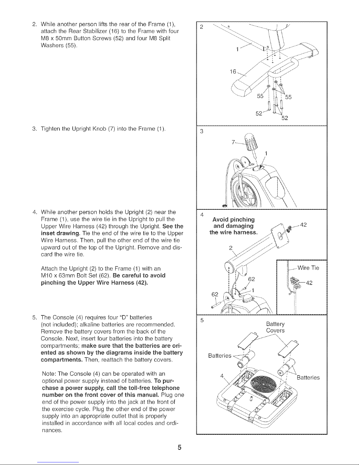
WhileanotherpersonliftstherearoftheFrame(1),
attachtheRearStabilizer(16)totheFramewithfour
M8x50mmButtonScrews(52)andfourM8Split
Washers(55).
55
3. TightentheUprightKnob(7)intotheFrame(1).
4. WhileanotherpersonholdstheUpright(2)nearthe
Frame(1),usethewiretieintheUprighttopullthe
UpperWireHarness(42)throughtheUpright.Seethe
insetdrawing.TietheendofthewiretietotheUpper
WireHarness.Then,pulltheotherendofthewiretie
upwardoutofthetopoftheUpright.Removeanddis-
cardthewiretie.
AttachtheUpright(2)totheFrame(1)withan
M10x 63mmBoltSet(62).Becarefultoavoid
pinching the Upper Wire Harness (42).
52
52
Avoid pinching
and damaging
the wire harness.
62
The Console (4) requires four "D" batteries
(not included); alkaline batteries are recommended.
Remove the battery covers from the back of the
Console. Next, insert four batteries into the battery
compartments; make sure that the batteries are ori-
ented as shown by the diagrams inside the battery
compartments. Then, reattach the battery covers.
Note: The Console (4) can be operated with an
optional power supply instead of batteries. To pur-
chase a power supply, call the tolFfree telephone
number on the front cover of this manual. Plug one
end of the power supply into the jack at the front of
the exercise cycle. Plug the other end of the power
supply into an appropriate outlet that is properly
installed in accordance with all local codes and ordi-
nances.
62
Battery
Covers
Batteries
4\
/ Batteries
5

Attach the Handlebar (39) to the Upright (2) with four
M6 x 3OHm Button Screws (37).
While another person holds the Console (4) near the
Handlebar (39), connect the console wire harness to
the Upper Wire Harness (42). Next, connect the pulse
wire on the Console to the Pulse Wire (51) in the
Handlebar. Note: The remaining wire (not shown) on
the Console is used during the manufacturing processl
disregard this wire.
Insert the excess wiring downward into the Upright (2).
Attach the Console (4) to the Handlebar (39) and the
Upright with four M4 x 16ram Round Head
Screws (80). Be careful to avoid pinching the
Wires (42, 51).
6
2
37
37
39
ConsoJe Wire
Harness
8O
PuJse
1
39
Wire
Slide the Bottom Handlebar Cover (18) into the slots in
the bottom of the Console (4). Attach the Bottom
Handlebar Cover to the Handlebar (39) and the Top
Handlebar Cover (84) with two M4 x 16ram Round
Head Screws (80) and one M4 x 12ram Screw (25).
Avoid pinching
the Wires (42, 51)
during this step.
25
 Loading...