

AUDIOS1RID It 8 0 0
Model No. 23667.0
Serial No.
Serial
Number
Decal
QUESTIONS?
As a manufacturer, we are com-
mitted to providing complete
customer satisfaction. If you
have questions, or if parts are
damaged or missing, PLEASE
CONTACT OUR CUSTOMER
SERVICE DEPARTMENT
DIRECTLY.
USER'S MANUAL
CALL TOLL-FREE:
1-888-825-2588
Mon.-Fri., 6 a.m.-6 p.m. MST
Sat, 8 a.m.-5 p.m. MST
ON THE WEB:
www.nordictrackservice.com
A CAUTION
Read all precautions and instruc-
tions in this manual before using
this equipment. Keep this manual
for future reference.
www.nordictrack.com
new products, prizes,
fitness tips, and much more!
AUDIOS IDER 8 0 0
TABLE OF CONTENTS
IMPORTANT PRECAUTIONS ................................................................ 3
BEFORE YOU BEGIN ...................................................................... 4
ASSEMBLY ............................................................................... 5
HOW TO USE THE ELLIPTICAL EXERCISER .................................................. 11
MAINTENANCE AND TROUBLESHOOTING ................................................... 19
CONDITIONING GUIDELINES ............................................................... 20
PART LIST .............................................................................. 24
EXPLODED DRAWING .................................................................... 26
ORDERING REPLACEMENT PARTS .................................................. Back Cover
LIMITED WARRANTY .............................................................. Back Cover
NordicTrack is a registered trademark of ICON IP, Inc.
2
IMPORTANT PRECAUTIONS
_WARN ING: To reduce the risk of serious injury, read the following important precau-
tions before using the elliptical exerciser.
Read all instructions in this manual and all
warnings on the elliptical exerciser before
using the elliptical exerciser. Use the ellipti-
cal exercise only as described in this
manual.
2.
It is the responsibility of the owner to ensure
that all users of the elliptical exerciser are
adequately informed of all precautions.
3.
The elliptical exerciser is intended for
home use only. Do not use the elliptical
exerciser in a commercial, rental, or institu- intended only as an exercise aid in determin-
tional setting, ing heart rate trends in general.
4. Keep the elliptical exerc iser indoors, away 11. Keep your back straight while using the ellip-
from moisture and dust. Place the elliptical
exerciser on a level surface, with a mat
beneath it to protect the floor or carpet.
Make sure that there is enough clearance
around the elliptical exerciser to mount, dis-
mount, and use it.
5. Inspect and properly tighten all parts regu-
larly. Replace any worn parts immediately. 14. The warning decals shown on page 4 have
6. Keep children under 12 and pets away from
the elliptical exerciser at all times.
7. The elliptical exerciser should not be used
by persons weighing more than 300 pounds.
8. Wear appropriate exercise clothes while
using the elliptical exerciser. Always wear
athletic shoes for foot protection while exer-
cising.
9. Hold the handgrip pulse sensors or the upper
body arms when mounting, dismounting, or
using the elliptical exerciser.
10. The pulse sensor is not a medical device.
Various factors may affect the accuracy of
heart rate readings. The pulse sensor is
tical exerciser; do not arch your back.
12. If you feel pain or dizziness while exercising,
stop immediately and cool down.
13. When you stop exercising, allow the pedals
to slowly come to a stop.
been placed on the elliptical exerciser in the
locations shown. If a decal is missing or
illegible, call the toll-free telephone number
on the front cover of this manual and order
a free replacement decal. Apply the decal in
the location shown.
AqLWARNING: Before beginning this or any exercise program, consult your physician.
This is especially important for persons over the age of 35 or persons with pre-existing health prob-
lems. Read all instructions before using. ICON assumes no responsibility for personal injury or
property damage sustained by or through the use of this product.
BEFORE YOU BEGIN
Thank you for purchasing the revolutionary
NordicTrack ®AUDIOSTRIDER 800 elliptical exerciser.
The AUDIOSTRIDER 800 elliptical exerciser provides
a wide array of features designed to make your work-
outs at home more effective and enjoyable--and
when you're not exercising, the unique elliptical exer-
ciser can be folded out of the way.
For your benefit, read this manual carefully before
you use the elliptical exerciser. If you have ques-
_tisuseof this machine
may result in serious
injury,
• Read user's raanual
priorto use and follow
all warnings and
instructions,
• DOnot allow children
on or around machine,
= Pedals continue to
spin when you stop
pedaling,
• Spinning pedals can
cause injury.
° Reduce pedal speed
in acontrolledmanner,
• User weight must not
exceed 300 pounds,
• Replace label if
damaged, illegible, or
removed.
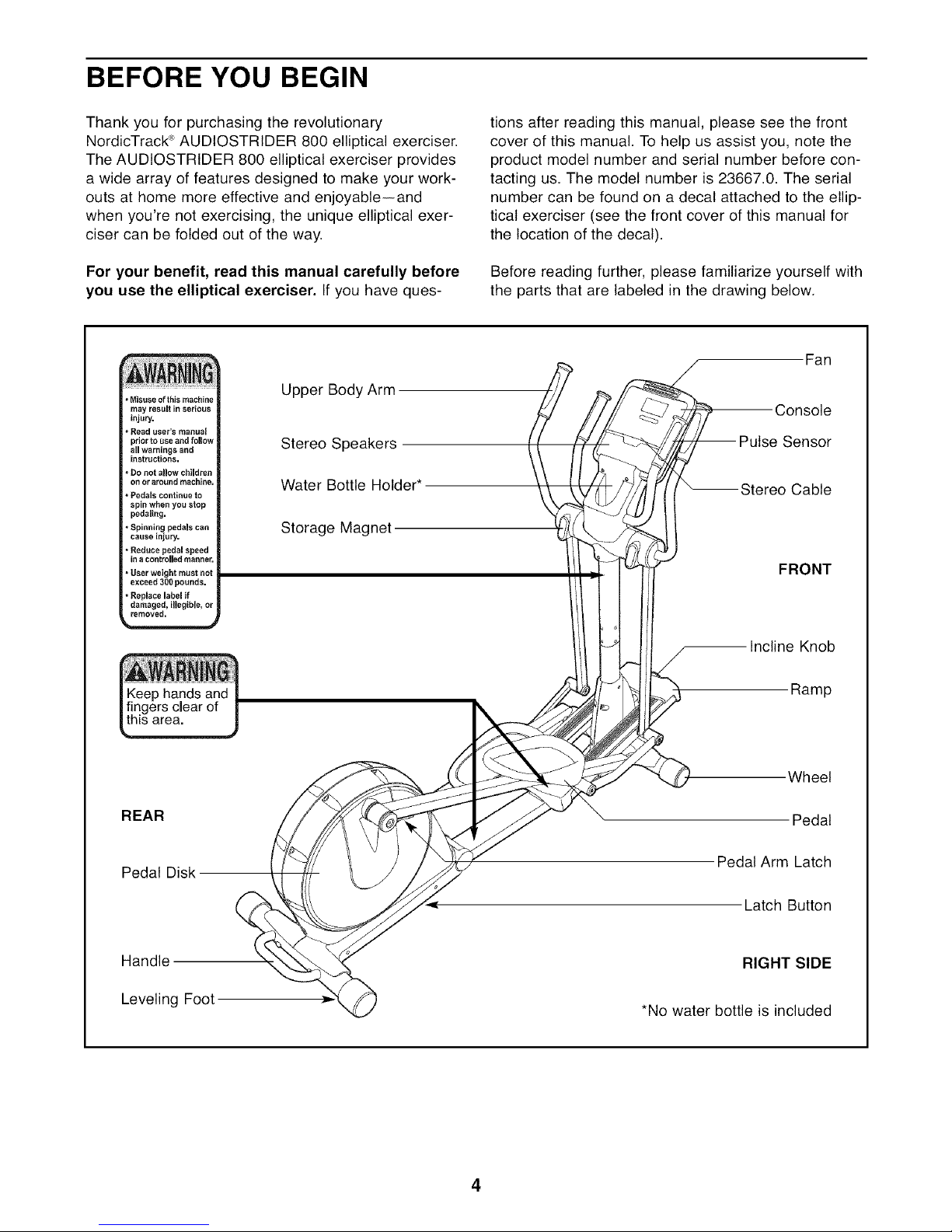
Upper Body Arm
Stereo Speakers
Water Bottle Holder*
Storage Magnet
tions after reading this manual, please see the front
cover of this manual. To help us assist you, note the
product model number and serial number before con-
tacting us. The model number is 23667.0. The serial
number can be found on a decal attached to the ellip-
tical exerciser (see the front cover of this manual for
the location of the decal).
Before reading further, please familiarize yourself with
the parts that are labeled in the drawing below.
Fan
Console
se Sensor
Stereo Cable
FRONT
clear of
"llsarea.
REAR
Pedal Disk
Handle
Leveling Foot
and
Incline Knob
Ramp
Wheel
Pedal
Pedal Arm Latch
Latch Button
RIGHT SIDE
*No water bottle is included
4
ASSEMBLY
Assembly requires two persons. Place all parts of the elliptical exerciser in a cleared area and remove the
packing materials. Do not dispose of the packing materials until assembly is completed.
Assembly requires the included hex keys and your own phillips screwdriver _-_-_ and rubber
mallet ___--i__-- __j) •
As you assemble the elliptical exerciser, use the drawings below to identify small parts. The number in parentheses
below each drawing is the key number of the part, from the PART LIST on pages 24 and 25. The number follow-
ing the parentheses is the quantity needed for assembly. Note: Some small parts may have been preassem-
bled. If a part is not in the parts bag, check to see if it has been preassembled.
\
M6 Split Washer M8 Split 1.5mm Washer M10 x 25mm M10 Curved Link Arm
(102)-8 Washer (101)-4 (103)-6 Washer (87)-2 Washer (99)-4 Spacer (74)-4
M4 x 16mm M6 x 35mm M6 x 62mm
Wave Washer Screw (116)-16 Screw (109)-4 Screw (108)-4
(100)-2
M8 x 15mm Button
Screw (106)-10
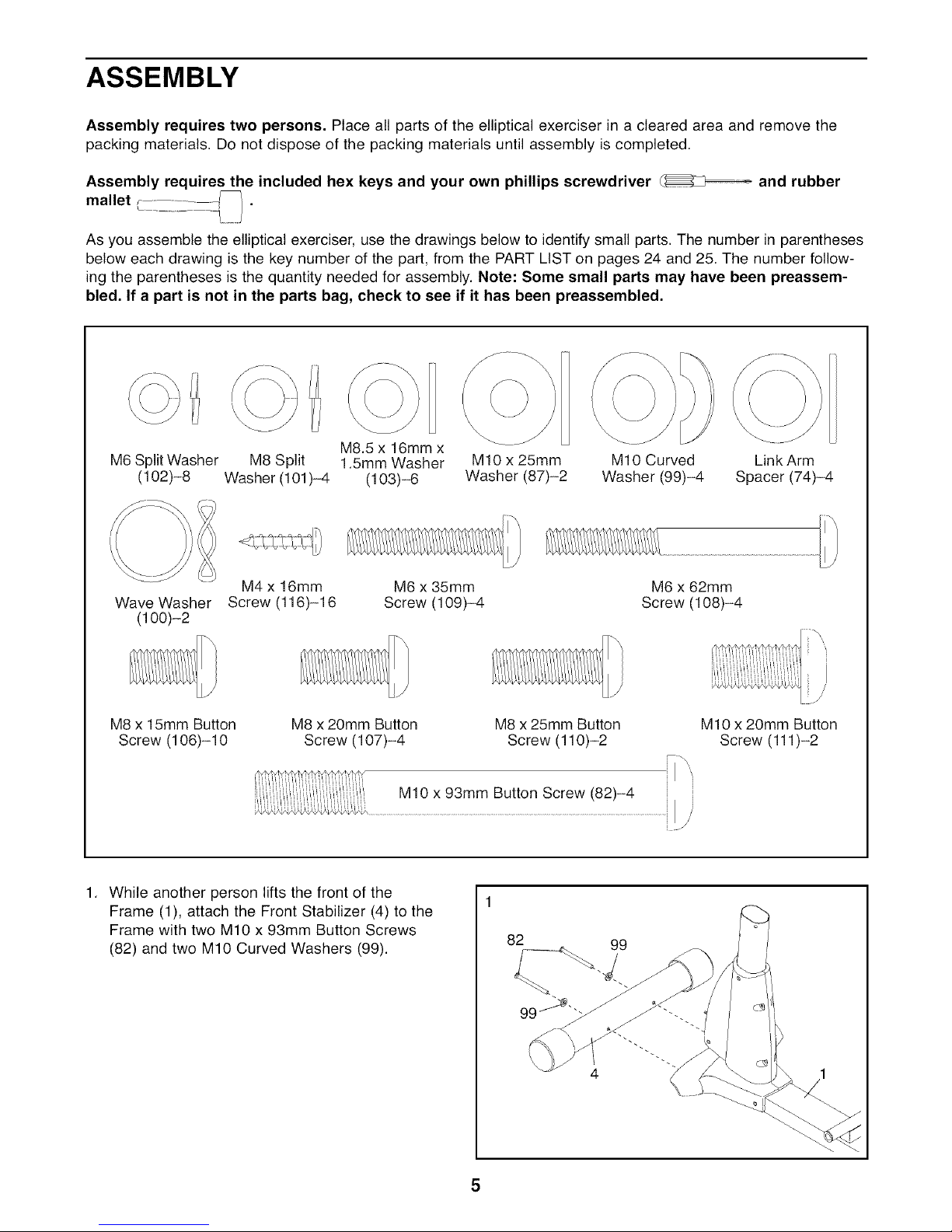
While another person lifts the front of the
Frame (1), attach the Front Stabilizer (4) to the
Frame with two M10 x 93mm Button Screws
(82) and two M10 Curved Washers (99).
M8 x 20mm Button
M8.5 x 16mm x
Screw (107)-4
M8 x 25mm Button
Screw (110)-2
M10 x 20mm Button
Screw (111)-2
4

2. While the other person lifts the Folding Frame
(2), attach the Rear Stabilizer (3) to the Folding
Frame with two M10 x 93mm Button Screws (82)
and two M10 Curved Washers (99). Next,
tighten the Center Foot (95) into the Frame (1).
3. Attach the Front Ramp Cover (6) to the
Ramp (5) with four M4 x 16mm Screws (116).
Slide an M10 x 25mm Washer (87) onto an
M10 x 20mm Button Screw (111). Tighten the
Button Screw into one end of the Ramp
Axle (72). Apply a small amount of the included
grease to the Ramp Axle.
95
99
62
Orient the Ramp (5) as shown. Align the lower
end of the Ramp with the welded tube on the
Frame (1). Insert the Ramp Axle (72) into the
Ramp and the welded tube. Then, pull the Ramp
Knob (9), lower the Ramp, and engage the
Ramp Pin (62) in one of the three adjustment
holes in the front of the Frame.
Slide an M10 x 25mm Washer (87) onto an
M10 x 20mm Button Screw (111). Tighten the
Button Screw into the open end of the Ramp
Axle (72).
116
Adjustment
Holes...._
87 111
72
Grease
6
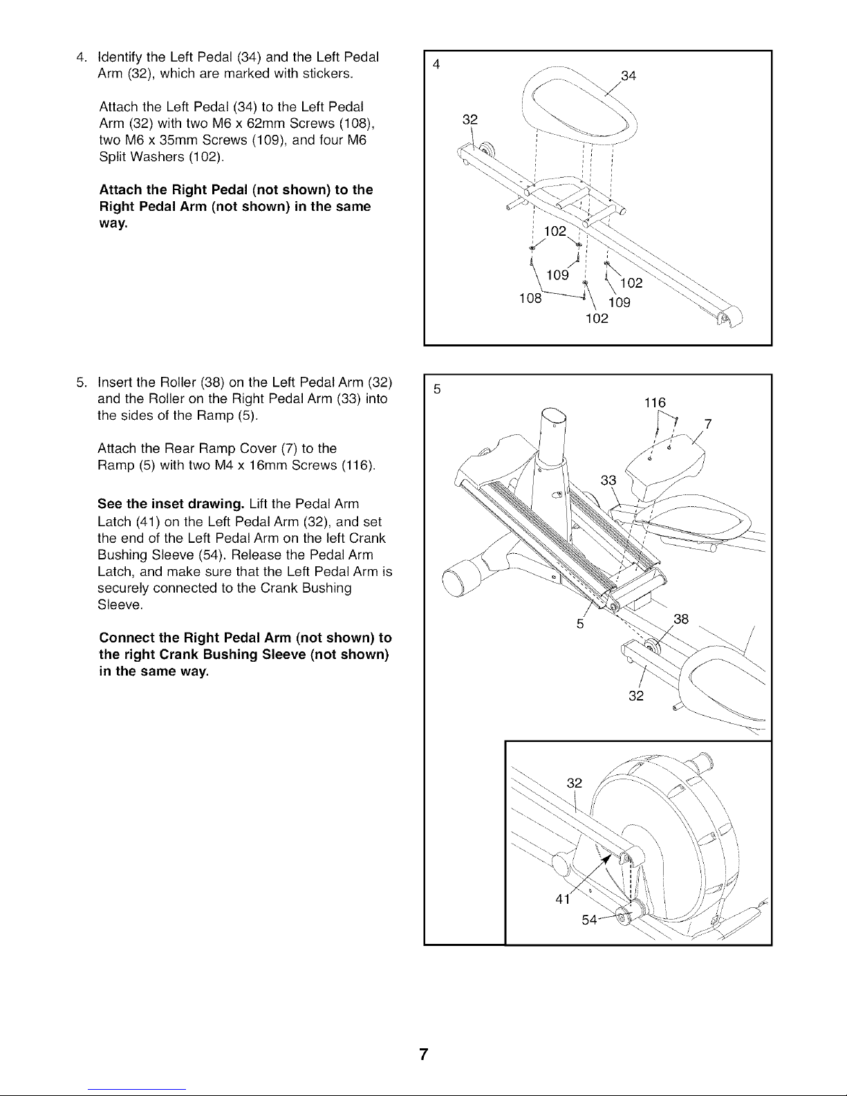
Identify the Left Pedal (34) and the Left Pedal
Arm (32), which are marked with stickers.
34
Attach the Left Pedal (34) to the Left Pedal
Arm (32) with two M6 x 62mm Screws (108),
two M6 x 35mm Screws (109), and four M6
Split Washers (102).
Attach the Right Pedal (not shown) to the
Right Pedal Arm (not shown) in the same
way.
5. Insert the Roller (38) on the Left Pedal Arm (32)
and the Roller on the Right Pedal Arm (33) into
the sides of the Ramp (5).
Attach the Rear Ramp Cover (7) to the
Ramp (5) with two M4 x 16mm Screws (116).
See the inset drawing, Lift the Pedal Arm
Latch (41) on the Left Pedal Arm (32), and set
the end of the Left Pedal Arm on the left Crank
Bushing Sleeve (54). Release the Pedal Arm
Latch, and make sure that the Left Pedal Arm is
securely connected to the Crank Bushing
Sleeve.
Connect the Right Pedal Arm (not shown) to
the right Crank Bushing Sleeve (not shown)
in the same way.
32 \
108
109
102
116
33
38
32
41
7

6. While another person holds the Upright (10)
near the Frame (1), connect the Upper Wire
Harness (65) to the Lower Wire Harness (64).
Carefully insert the Upright (10) into the
Frame (1); be careful not to damage the Wire
Harnesses (64, 65). Attach the Upright with four
M8 x 20mm Button Screws (107) and four M8
Split Washers (101).
Be careful not
to damage the
Wire Harnesses
(64, 65) during
this step.
101
Z
107
Y2
01
7,
Attach the Left Upper Body Arm (22) to the left
Upper Body Leg (24) with three M8 x 15mm
Button Screws (106).
Attach the Right Upper Body Arm (23) in the
same way.
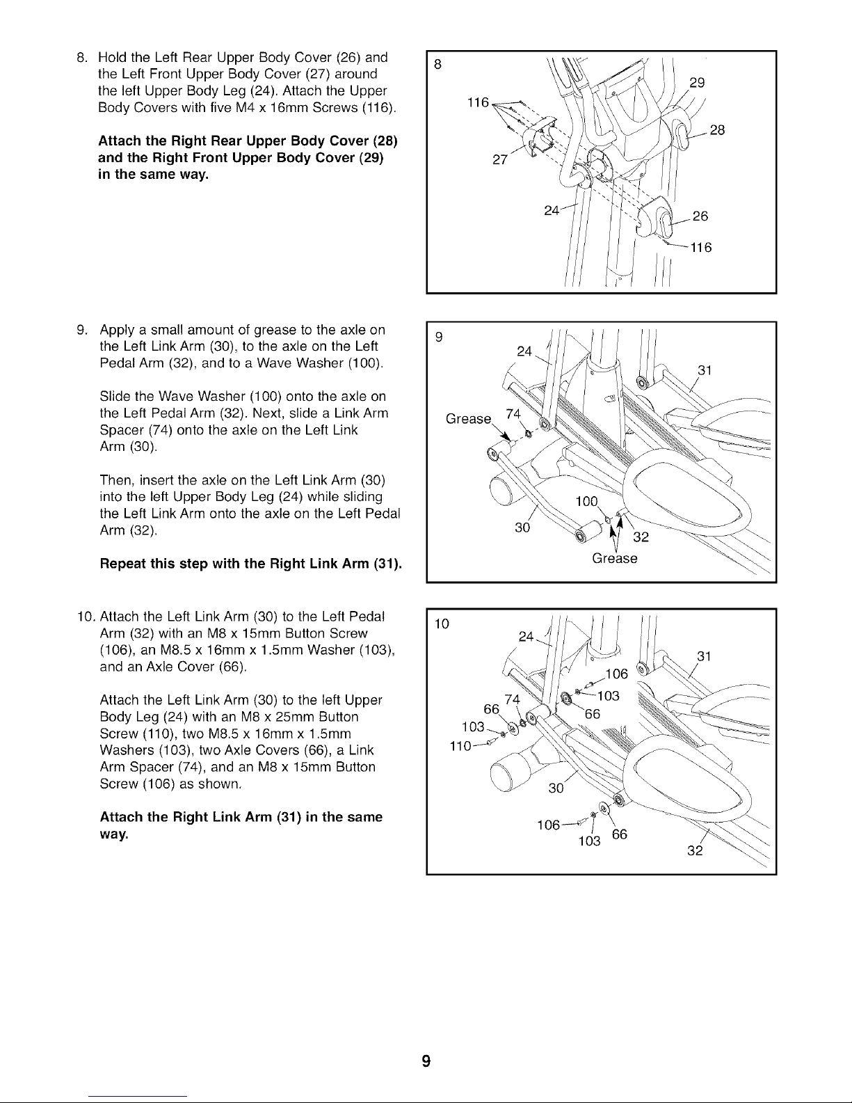
Hold the Left Rear Upper Body Cover (26) and
8. 8
the Left Front Upper Body Cover (27) around
the left Upper Body Leg (24). Attach the Upper
Body Covers with five M4 x 16mm Screws (116).
Attach the Right Rear Upper Body Cover (28)
and the Right Front Upper Body Cover (29)
in the same way.
.
Apply a small amount of grease to the axle on
the Left Link Arm (30), to the axle on the Left
Pedal Arm (32), and to a Wave Washer (100).
Slide the Wave Washer (100) onto the axle on
the Left Pedal Arm (32). Next, slide a Link Arm
Spacer (74) onto the axle on the Left Link
Arm (30).
29
116,
27
Grease\
Then, insert the axle on the Left Link Arm (30)
into the left Upper Body Leg (24) while sliding
the Left Link Arm onto the axle on the Left Pedal
Arm (32).
Repeat this step with the Right Link Arm (31),
10. Attach the Left Link Arm (30) to the Left Pedal
Arm (32) with an M8 x 15mm Button Screw
(106), an M8.5 x 16mm x 1.5mm Washer (103),
and an Axle Cover (66).
Attach the Left Link Arm (30) to the left Upper
Body Leg (24) with an M8 x 25mm Button
Screw (110), two M8.5 x 16mm x 1.5mm
Washers (103), two Axle Covers (66), a Link
Arm Spacer (74), and an M8 x 15mm Button
Screw (106) as shown.
Attach the Right Link Arm (31) in the same
way.
10
30
32
Grease
66
32
9
 Loading...