

Page 1
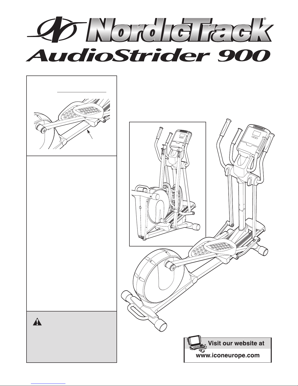
Model No. NTEVEL99007.0
Serial No.
Serial Number
Decal
QUESTIONS?
As a manufacturer, we are committed to providing complete customer
satisfaction. If you have questions,
or if there are missing parts, please
contact us:
Call: 08457 089 009
Outside UK: 0 (44) 113 3877133
USER’S MANUAL
Fax: 0 (44) 113 3877125
Email: csuk@iconeurope.com
Write:
ICON Health & Fitness, Ltd.
Unit 4
Revie Road Industrial Estate
Revie Road, Beeston
Leeds, LS11 8JG,
UK
CAUTION
Read all precautions and instructions in this manual before using
this equipment. Keep this manual
for future reference.
Page 2
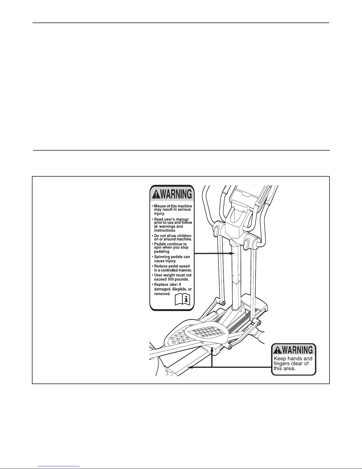
TABLE OF CONTENTS
166909
218557
218556
2
ARNING DECAL PLACEMENT . . . . . . . . . . . . . . . . . . . . . . . . . . . . . . . . . . . . . . . . . . . . . . . . . . . . . . . . . . . . . .2
W
IMPORTANT PRECAUTIONS . . . . . . . . . . . . . . . . . . . . . . . . . . . . . . . . . . . . . . . . . . . . . . . . . . . . . . . . . . . . . . . .3
BEFORE YOU BEGIN . . . . . . . . . . . . . . . . . . . . . . . . . . . . . . . . . . . . . . . . . . . . . . . . . . . . . . . . . . . . . . . . . . . . . .4
ASSEMBLY . . . . . . . . . . . . . . . . . . . . . . . . . . . . . . . . . . . . . . . . . . . . . . . . . . . . . . . . . . . . . . . . . . . . . . . . . . . . . . .5
OW TO USE THE CHEST PULSE SENSOR . . . . . . . . . . . . . . . . . . . . . . . . . . . . . . . . . . . . . . . . . . . . . . . . . .12
H
HOW TO USE THE ELLIPTICAL EXERCISER . . . . . . . . . . . . . . . . . . . . . . . . . . . . . . . . . . . . . . . . . . . . . . . . . .13
MAINTENANCE AND TROUBLESHOOTING . . . . . . . . . . . . . . . . . . . . . . . . . . . . . . . . . . . . . . . . . . . . . . . . . . .24
EXERCISE GUIDELINES . . . . . . . . . . . . . . . . . . . . . . . . . . . . . . . . . . . . . . . . . . . . . . . . . . . . . . . . . . . . . . . . . . .26
PART LIST . . . . . . . . . . . . . . . . . . . . . . . . . . . . . . . . . . . . . . . . . . . . . . . . . . . . . . . . . . . . . . . . . . . . . . . . . . . . . .28
EXPLODED DRAWING . . . . . . . . . . . . . . . . . . . . . . . . . . . . . . . . . . . . . . . . . . . . . . . . . . . . . . . . . . . . . . . . . . . .30
ORDERING REPLACEMENT PARTS . . . . . . . . . . . . . . . . . . . . . . . . . . . . . . . . . . . . . . . . . . . . . . . . . .Back Cover
WARNING DECAL PLACEMENT
The warning decalS shown here
have been applied in the locations shown. If a decal is miss-
ing or illegible, call the telephone number on the front
cover of this manual and
request a free replacement
decal. Apply the decal in the
location shown. Note: The
decal may not be shown at actual size.
NordicTrack is a registered trademark of ICON IP, Inc.
2
Page 3

IMPORTANT PRECAUTIONS
WARNING: To reduce the risk of serious injury, read all important precautions and
instructions in this manual and all warnings on your elliptical exerciser before using your elliptical
exerciser. ICON assumes no responsibility for personal injury or property damage sustained by or
through the use of this product.
1. Before beginning any exercise program,
consult your physician. This is especially
important for persons over the age of 35 or
persons with pre-existing health problems.
2. It is the responsibility of the owner to ensure
that all users of the elliptical exerciser are
adequately informed of all precautions.
3. Your elliptical exerciser is intended for home
use only
in a commercial, rental, or institutional setting.
4. Keep your elliptical exerciser indoors, away
from moisture and dust. Place your elliptical
exerciser on a level surface, with a mat
beneath it to protect the floor or carpet.
Make sure that there is enough clearance
around your elliptical exerciser to mount,
dismount, and use it.
5. Inspect and properly tighten all parts regularly. Replace any worn parts immediately.
6. Keep children under age 12 and pets away
from your elliptical exerciser at all times.
7. Your elliptical exerciser should not be used
by persons weighing more than 325 lbs.
(147 kg).
. Do not use your elliptical exerciser
8. Wear appropriate exercise clothes when
exercising; do not wear loose clothes that
could become caught on your elliptical exerciser. Always wear athletic shoes for foot
protection.
9. Hold the handgrip pulse sensor or the upper
body arms
using your elliptical
Keep your back straight while using your
10.
elliptical exerciser; do not arch your back.
11. The pulse sensor is not a medical device.
Various factors, including the user’s movement, may affect the accuracy of heart rate
readings. The pulse sensor is intended only
as an exercise aid in determining heart rate
trends in general.
12. When you stop exercising, allow the pedals
to slowly come to a stop.
13. If you feel pain or dizziness while exercising,
stop immediately and cool down.
14. Use your elliptical exerciser only as
described in this manual.
when mounting, dismounting, or
exerciser.
3
Page 4
BEFORE YOU BEGIN
Thank you for purchasing the revolutionary
ordicTrack
N
The AUDIOSTRIDER 900 elliptical exerciser provides
an array of features designed to make your workouts
at home more effective and enjoyable—and when
you’re not exercising, the unique elliptical exerciser
can be folded out of the way.
For your benefit, read this manual carefully before
you use the elliptical exerciser.
®
UDIOSTRIDER 900 elliptical exerciser.
A
If you have ques-
Stereo Cable
Upper Body Arm
Water Bottle Holder*
Storage Magnet
tions after reading this manual, please see the front
over of this manual. To help us assist you, note the
c
product model number and serial number before contacting us. The model number and the location of the
serial number decal are shown on the front cover of
this manual.
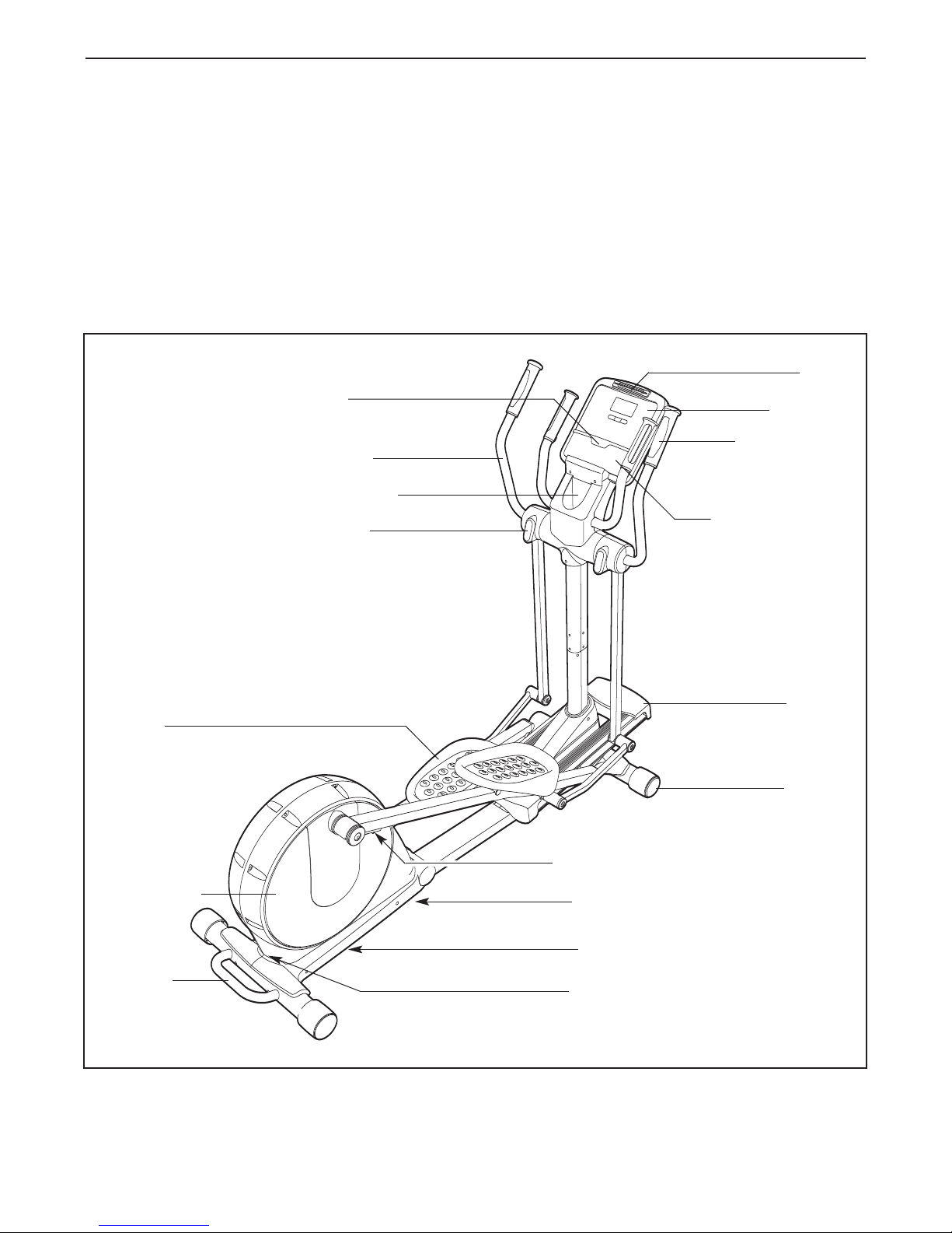
Before reading further, please familiarize yourself with
the parts that are labeled in the drawing below.
Fan
Console
Pulse Sensor
Stereo Speakers
Pedal
Pedal Disc
Handle
*No water bottle is included
Ramp
Wheel
Pedal Arm Latch
Leveling Foot
Latch Button
Power Socket
4
Page 5

ASSEMBLY
M10 x 93mm Patch Screw (82)–4
M10 x 25mm
Washer (87)–2
M8 Split Washer
(101)–4
M4 x 16mm
Screw
(116)–16
M6 Split Washer
(102)–8
M6 x 35mm Patch Screw
(109)–4
M6 x 62mm Patch Screw
(108)–4
M8.5 x 16mm x
1.5mm Washer
(103)–6
Link Arm
Spacer (74)–4
M8 x 20mm Patch Screw
(107)–4
M10 x 20mm Patch
Screw (111)–2
M8 x 15mm Patch
Screw
(106)–10
M10 Curved
Washer (99)–4
Wave Washer
(100)–2
M8 x 25mm Patch
Screw (136)–2
Assembly requires two persons. Place all parts of the elliptical exerciser in a cleared area and remove the
acking materials. Do not dispose of the packing materials until assembly is completed.
p
Assembly requires the included hex keys and your own Phillips screwdriver and rubber
mallet .
As you assemble the elliptical exerciser, use the drawings below to identify small parts. The number in parentheses below each drawing is the key number of the part, from the PART LIST near the end of this manual. The
number following the parentheses is the quantity needed for assembly.
been preassembled. If a part is not in the hardware kit, check to see if it has been preassembled.
Note: Some small parts may have
5
Page 6
1. If there is a shipping bracket attached to the
rear of the Folding Frame (not shown), remove
the screw and the shipping bracket from the
Folding Frame. Discard the screw and the shipping bracket.
1
82
99
1
See HOW TO FOLD AND UNFOLD THE
ELLIPTICAL EXERCISER on page 13 and
unfold the elliptical exerciser.
While another person lifts the front of the Frame
(1), attach the Front Stabilizer (4) to the Frame
with two M10 x 93mm Patch Screws (82) and
two M10 Curved Washers (99).
2. While another person lifts the Folding Frame
(2), attach the Rear Stabilizer (3) to the Folding
Frame with two M10 x 93mm Patch Screws (82)
and two M10 Curved Washers (99). Next, tighten the Center Foot (95) into the Frame (1).
99
4
2
1
3
95
99
2
99
82
6
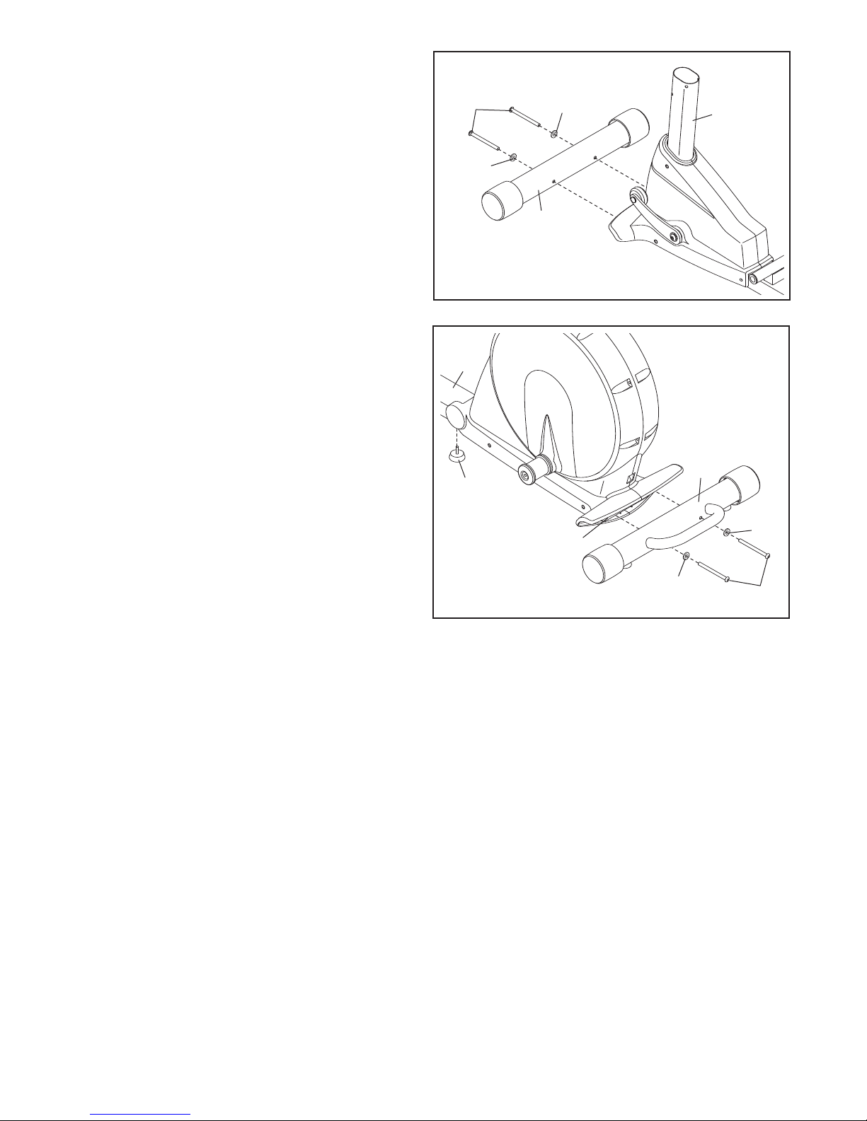
Page 7
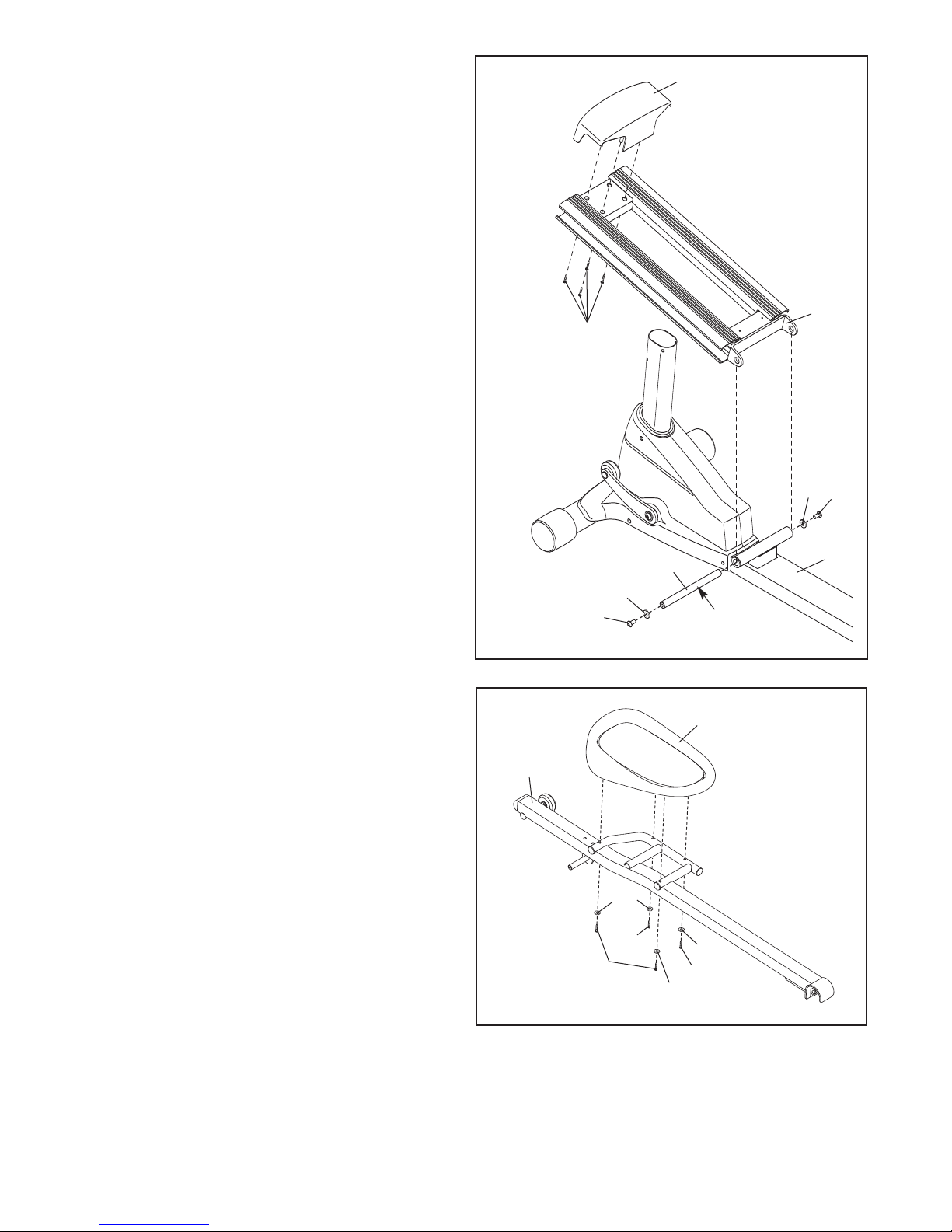
3. Attach the Front Ramp Cover (6) to the
Ramp (5) with four M4 x 16mm Screws (116).
Slide an M10 x 25mm Washer (87) onto an
M10 x 20mm Patch Screw (111). Tighten the
Button Screw into one end of the Ramp
xle (72). Apply a small amount of the included
A
rease to the Ramp Axle.
g
Orient the Ramp (5) as shown. Align the lower
end of the Ramp with the welded tube on the
Frame (1). Insert the Ramp Axle (72) into the
Ramp and the welded tube.
Slide an M10 x 25mm Washer (87) onto an
M10 x 20mm Patch Screw (111). Tighten the
Button Screw into the open end of the Ramp
Axle (72).
3
116
6
5
87
111
4. Identify the Left Pedal (34) and the Left Pedal
Arm (32), which are marked with stickers.
Attach the Left Pedal (34) to the Left Pedal
(32) with two M6 x 62mm Patch Screws
Arm
(108), two M6 x 35mm Patch Screws (109), and
four M6 Split Washers (102).
Attach the Right Pedal (not shown) to the
Right Pedal Arm (not shown) in the same
way.
72
87
111
4
32
102
109
108
Grease
34
102
109
102
1
7
Page 8
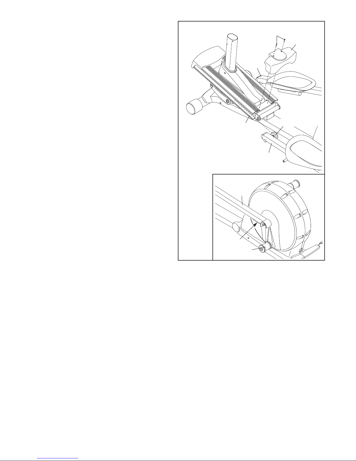
5. Insert the Roller (38) on the Left Pedal Arm (32)
nd the Roller on the Right Pedal Arm (33) into
a
the sides of the Ramp (5).
Attach the Rear Ramp Cover (7) to the Ramp
(5) with two M4 x 16mm Screws (116).
See the inset drawing. Lift the Pedal Arm
Latch (41) on the Left Pedal Arm (32) and set
the end of the Left Pedal Arm on the left Crank
Bushing Sleeve (54). Release the Pedal Arm
Latch; make sure that the Left Pedal Arm is
securely connected to the Crank Bushing
Sleeve.
Connect the Right Pedal Arm (33) to the
right Crank Bushing Sleeve (not shown) in
the same way.
5
116
7
3
3
5
32
32
38
41
54
8
Page 9

6. While another person holds the Upright (10)
near the Frame (1), connect the Upper Wire
arness (65) to the Lower Wire Harness (64).
H
arefully insert the Upright (10) into the
C
Frame (1); be careful not to damage the Wire
Harnesses (64, 65). Attach the Upright with
four M8 x 20mm Patch Screws (107) and four
M8 Split Washers (101).
6
e careful not
B
to damage the
Wire Harnesses
(64, 65) during
this step
101
10
65
107
64
101
7. Attach the Left Upper Body Arm (22) to the left
Upper Body Leg (24) with three M8 x 15mm
Patch Screws (106).
Attach the Right Upper Body Arm (23) in the
same way.
107
7
22
106
24
1
23
9
Page 10
8. Hold the Left Rear Upper Body Cover (26) and
the Left Front Upper Body Cover (27) around
he left Upper Body Leg (24). Attach the Upper
t
Body Covers with five M4 x 16mm Screws (116).
Attach the Right Rear Upper Body Cover
(28) and the Right Front Upper Body Cover
29) in the same way.
(
8
29
16
1
8
2
27
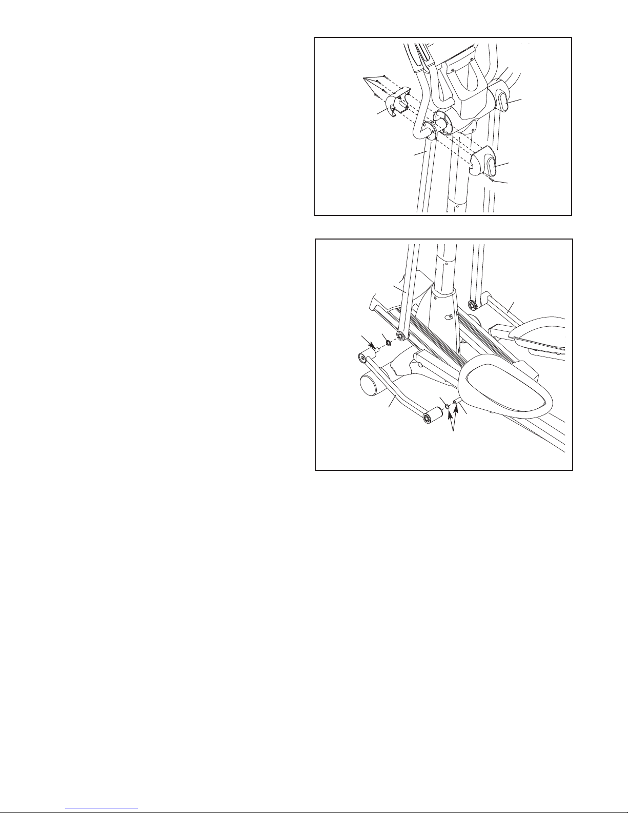
9. Apply a small amount of grease to the axle on
the Left Link Arm (30), to the axle on the Left
Pedal Arm (32), and to a Wave Washer (100).
Slide the Wave Washer (100) onto the axle on
the Left Pedal Arm (32). Next, slide a Link Arm
Spacer (74) onto the axle on the Left Link
Arm (30).
Then, insert the axle on the Left Link Arm (30)
into the left Upper Body Leg (24) while sliding
the Left Link Arm onto the axle on the Left
Pedal Arm (32).
Repeat this step with the Right Link
Arm (31).
9
Grease
74
24
30
24
26
116
31
100
32
Grease
10
Page 11

10. Attach the Left Link Arm (30) to the Left Pedal
Arm (32) with an M8 x 15mm Patch Screw
(106), an M8.5 x 16mm x 1.5mm Washer (103),
nd an Axle Cover (66).
a
ttach the Left Link Arm (30) to the left Upper
A
Body Leg (24) with an M8 x 25mm Patch Screw
136), two M8.5 x 16mm x 1.5mm Washers
(
(103), two Axle Covers (66), a Link Arm Spacer
(74), and an M8 x 15mm Patch Screw (106) as
shown.
10
103
136
24
31
106
74
6
6
103
6
6
Attach the Right Link Arm (31) in the same
way.
11. Plug the power cord into the power socket at the rear of the elliptical exerciser (see HOW TO PLUG IN THE
POWER CORD on page 13). IMPORTANT: If the elliptical exerciser has been exposed to cold tempera-
tures, allow it to warm to room temperature before plugging in the power cord. If you do not do this,
the console displays or other electronic components may become damaged.
Make sure that all parts of the elliptical exerciser are properly tightened. Note: Some hardware may be
left over after assembly is completed. To protect the floor or carpet from damage, place a mat under the
elliptical exerciser.
30
106
103
66
32
11
Page 12

HOW TO USE THE CHEST PULSE SENSOR
HOW TO PUT ON THE CHEST PULSE SENSOR
The chest pulse sensor consists of two components:
he chest strap and the sensor unit (see the drawing
t
below). Insert the tab on one end of the chest strap
into one end of the sensor unit, as shown in the inset
drawing. Press the end of the sensor unit under the
buckle on the chest strap. The tab should be flush with
the front of the sensor unit.
Chest Strap
ab
T
Sensor Unit
Next, wrap the
chest pulse sensor around your
chest and attach
the other end of
the chest strap to
the sensor unit.
Adjust the length
of the chest strap, if necessary. The chest pulse sensor should be under your clothes, tight against your
skin, and as high under the pectoral muscles or
breasts as is comfortable. Make sure that the logo on
the sensor unit is facing forward and is right-side-up.
Sensor
Unit
Logo
Buckle
• Store the chest pulse sensor in a warm, dry place.
o not store the chest pulse sensor in a plastic bag
D
or other container that may trap moisture.
• Do not expose the chest pulse sensor to direct sun-
light for extended periods of time; do not expose it
to temperatures above 122° F (50° C) or below 14°
F (-10° C).
• Do not excessively bend or stretch the sensor unit
when using or storing the chest pulse sensor.
• Clean the sensor unit using a damp cloth—never
use alcohol, abrasives, or chemicals. The chest
strap may be hand washed and air dried.
CHEST PULSE SENSOR TROUBLESHOOTING
The instructions below explain how the chest
pulse sensor is used with the console. If the chest
pulse sensor does not function properly, try the
steps below.
• Make sure that you are wearing the chest pulse sen-
sor as described at the left. Note: If the chest pulse
sensor does not function when positioned as
described, move it slightly lower or higher.
• Use saline solution such as saliva or contact lens
solution to wet the two electrode areas on the sensor unit. If heart rate readings do not appear until
you begin perspiring, re-wet the electrode areas.
• Make sure to position yourself near the console.
the console to display heart rate readings, the
user must be within arm’s length of the console.
For
Pull the sensor unit away from your body a few inches
and locate the two electrode areas on the inner side
(the electrode areas are covered by shallow ridges).
Using saline solution such as saliva or contact lens
solution, wet both electrode areas. Return the sensor
unit to a position against your chest.
CHEST PULSE SENSOR
• Thoroughly dry the chest pulse sensor after each
The chest pulse sensor is activated when the
use.
electrode areas are wetted and the heart rate monitor is put on; the chest pulse sensor shuts off when
it is removed and the electrode areas are dried. If
the chest pulse sensor is not dried after each use, it
may remain activated longer than necessary, draining the battery prematurely.
CARE
The chest pulse sensor is designed to work with
•
people who have normal heart rhythms. Heart rate
reading problems may be caused by medical conditions such as premature ventricular contractions
(pvcs), tachycardia bursts, and arrhythmia.
The operation of the chest pulse sensor can be
•
fected by magnetic interference caused by high
af
power lines or other sources. If it is suspected that
this is a problem, try relocating the exercise cycle.
12
Page 13

HOW TO USE THE ELLIPTICAL EXERCISER
U
UK
HOW TO PLUG IN THE POWER CORD
DANGER: Improper connection of
the equipment-earthing conductor can result
in an increased risk of electric shock. Check
with a qualified electrician or serviceman if
you are in doubt as to whether the product is
properly earthed. Do not modify the plug provided with the product—if it will not fit the outlet, have a proper outlet installed by a qualified electrician.
This product must be earthed. If it should malfunc-
tion or break down, earthing provides a path of least
resistance for electric current to reduce the risk of
electric shock. This product is equipped with a cord
having an equipment-earthing conductor and an earthing plug.
replaced with a manufacturer-recommended
power cord.
Two power cords
are included.
Select the one
that will fit your
outlet. Refer to
drawing 1, and
plug the indicated
end of the power
cord into the socket at the back of
the elliptical exer
ciser.
If the power cord is damaged, it must be
1
Socket on
Elliptical
Exerciser
-
HOW TO FOLD AND UNFOLD THE ELLIPTICAL
EXERCISER
When the elliptical exerciser is not in use, the frame
can be folded out of the way. First, lift the latch under
each pedal arm, and lift the pedal arms off the sleeves
on the crank arms.
Pedal
Sleeve
Next, raise the pedal arms until they touch the magnets on the upper body legs; the magnets will hold the
pedal arms in place. Then, hold the handle and lift the
frame until it locks in a vertical position.
Handle
Latch
Button
Arm
Latch
Magnet
Pedal Arm
Refer to drawing 2.
Plug the power
cord into an appropriate outlet that is
properly installed
and earthed in
accordance with all
local codes and
ordinances. Note:
In Italy, an adaptor (not included)
must be used
between the power cord and the outlet. IMPORTANT: The elliptical exerciser is not compatible
with GFCI-equipped outlets.
2
Outlet
To use the elliptical exerciser, first hold the handle,
press the latch button, and lower the frame.
Next, pull the pedal arms off the magnets on the upper
body legs. Then,
arms, and set the pedal arms on the sleeves on the
crank arms. Release the latches, and make sure that
the pedal arms are securely connected to the crank
arms.
lift the latches under the pedal
13
Page 14

OW TO MOVE THE ELLIPTICAL EXERCISER
H
To move the elliptical exerciser, first fold it as
described on page 13. Next, stand in front of the ellip-
ical exerciser, hold the handgrip pulse sensors, and
t
place one foot against the center of the front stabilizer.
Pull the pulse sensors until the elliptical exerciser will
roll on the front wheels. Carefully move the elliptical
exerciser to the desired position, and then lower it.
Handgrip
Pulse
Sensors
OW TO EXERCISE ON THE ELLIPTICAL
H
EXERCISER
To mount the elliptical exerciser, hold the upper body
rms and step onto the pedal that is in the lowest
a
position. Next, step onto the other pedal. Push the
pedals until they begin to move with a continuous
motion.
Note: The crank arms can turn in either direction.
It is recommended that you turn the crank arms in
the direction shown by the arrow below; however,
for variety you can turn the crank arms in the
opposite direction.
Upper Body Arms
Place
your foot
here
HOW TO LEVEL THE ELLIPTICAL EXERCISER
If the elliptical
exerciser rocks
on your floor during use, turn one
or both of the leveling feet
beneath the rear
stabilizer until the
rocking motion is
eliminated. If the
elliptical exerciser
flexes in the center during use,
turn the center foot beneath the frame until the flexing
is eliminated.
Leveling
Feet
Center
Foot
Pedals
Crank Arm
o dismount the elliptical exerciser, wait until the ped-
T
als come to a complete stop. Note: The elliptical
exerciser does not have a free wheel; the pedals
will continue to move until the flywheel stops.
When the pedals are stationary
pedal first. Then, step off the lower pedal.
, step off the higher
14
Page 15

CONSOLE DIAGRAM
FEATURES OF THE CONSOLE
The advanced console offers an array of features
designed to make your workouts more effective and
enjoyable. When you select the manual mode of the
console, you can change the resistance of the pedals
and the incline of the ramp with the touch of a button.
As you exercise, the console will provide continuous
exercise feedback. You can even measure your heart
rate using the handgrip pulse sensor or the included
chest pulse sensor.
The console also offers twenty preset workouts. Each
workout automatically changes the resistance of the
pedals and prompts you to increase or decrease your
pedaling pace as it guides you through an effective
workout.
The console also offers two custom workouts that
allow you to create your own workouts and store them
in memory for future use.
In addition, the console features two heart rate workouts that change the resistance of the pedals to keep
your heart rate near target heart rate settings while
you exercise.
The console also features the new iFIT Interactive
Workout System. The iFIT Interactive Workout System
enables the console to accept iFIT cards containing
workouts designed to help you achieve specific fitness
goals. For example, lose unwanted pounds with the 8week Weight Loss workout. iFIT workouts control the
resistance of the pedals while the voice of a personal
trainer coaches and motivates you through your work-
To purchase iFIT cards, go to www.iFIT.com
outs.
or call the telephone number on the front cover of
this manual. iFIT cards are also available at select
stores.
You can even connect your MP3 player or CD player
to the console’s stereo sound system and listen to
your favorite music or audio books while you exercise.
To use the manual mode of the console, follow the
steps beginning on page 16. To use a preset work-
out, see page 18. To create a custom workout, see
page 19. To use a custom workout, see page 20. To
use a heart rate workout, see page 21. To use an
iFIT workout, see page 23. To use the stereo sound
system, see page 23.
15
Page 16

HOW TO USE THE MANUAL MODE
ote: If there is a sheet of clear plastic on the face of
N
the console, remove the plastic.
1. Press any button on the console or begin pedling to turn on the console.
a
hen you turn on the console, the display will
W
light. A tone will then sound and the console will
be ready for use.
2. Select the manual mode.
When you turn on the console, the manual mode
will be selected. If you have selected a workout,
reselect the manual mode by pressing any of the
Programs buttons repeatedly until zeros appear in
the display.
The upper right corner of the display will show the
distance you have pedaled, in total revolutions.
The display will also show your heart rate when
you use the handgrip pulse sensor (see step 5 on
page 17).
The lower left corner of the display will show the
ramp incline level.
The lower center of the display will show the
approximate number of grams of carbs you have
burned.
The lower right corner of the display will show your
pedaling pace, in revolutions per minute.
3. Begin pedaling and change the resistance of
the pedals and the incline of the ramp as
desired.
As you pedal, change the resistance of the pedals
by pressing the OneTouch Resistance buttons.
There are fifteen resistance levels. Note: After you
press the buttons, it will take a moment for the
pedals to reach the selected resistance level.
o vary the motion of the pedals, you can change
T
the incline of the ramp. To change the incline,
press the OneTouch Ramp buttons. There are five
incline levels. Note: After you press the buttons, it
will take a moment for the ramp to reach the
selected incline level.
4. Follow your progress with the display.
While you pedal, the upper left corner of the display will show the elapsed time. Note: During a
workout, except for heart rate workout 1, the display will show the time remaining in the workout.
The center of the display will show the resistance
level of the pedals for a few seconds each time
the resistance level changes.
You can also view selected information at a larger
size. Press the Display button repeatedly to view
the elapsed time and the distance you have pedaled, the elapsed time and the approximate number of calories you have burned, the elapsed time,
or the approximate number of calories you have
burned. Press the Display button again to view a
workout history of resistance levels and pedaling
pace.
To again view the time, distance, ramp incline,
number of grams of carbs burned, and pedaling
pace, press the Display button again.
To view the total distance pedaled since the elliptical exerciser was purchased and the trip distance,
press the Odometer button. The information will
o reset
appear in the display for a few seconds.
the trip distance, hold down the Odometer button
for a few seconds.
T
16
Page 17

5. Measure your heart rate if desired.
To use the included chest pulse sensor, see page
12. To use the handgrip pulse sensor, follow the
instructions below.
ulse sensor and hold the handgrip pulse sen-
p
sor at the same time, the console will not display your heart rate accurately.
If there are sheets
of clear plastic on
the metal contacts on the
handgrip pulse
sensor, remove
the plastic. In
addition, make
sure that your
hands are clean.
To measure your
heart rate, hold the
handgrip pulse sensor with your palms resting
against the metal contacts.
hands or gripping the contacts tightly.
Note: If you wear the chest
Contacts
Avoid moving your
squeeze the metal contacts tightly. For optimal
erformance, clean the metal contacts using a soft
p
cloth;
never use alcohol, abrasives, or chemi-
cals to clean the contacts.
. Turn on the fan if desired.
6
To turn on the fan at high speed, press the Fan
button. To turn on the fan at low speed, press the
Fan button a second time. To select the auto
mode, press the Fan button again; when the auto
mode is selected, the speed of the fan will automatically increase or decrease as you increase or
decrease your pedaling speed.
Pivot the fan louvers above the display upward or
downward to direct the airflow from the fan.
To turn off the fan, press the Fan button again.
Note: If the pedals are not moved for about thirty
seconds, the fan will automatically turn off.
7. When you are finished exercising, the console
will turn off automatically.
When your pulse is detected, your heart rate will
be shown in the display. For the most accurate
heart rate reading, hold the contacts for at least 15
seconds.
If your heart rate is not shown, make sure that
your hands are positioned as described. Be careful not to move your hands excessively or to
If the pedals are not moved for several seconds, a
series of tones will sound and the console will
pause.
If the pedals are not moved for about five minutes,
the console will turn off and the display will be
reset.
17
Page 18

HOW TO USE A PRESET WORKOUT
1. Turn on the console.
See step 1 on page 16.
2. Select a preset workout.
To select a weight loss workout, press the Weight
Loss Programs button repeatedly; to select an aerobic fitness workout, press the Aerobic Fitness
Programs button; to select a competition workout,
press the Competition Programs button.
When you select a preset workout, the name of
the workout, the workout time, and the maximum
pace and resistance level for the workout will
appear in the display for a few seconds. A profile
of the resistance levels of the workout will then
appear in the display.
Profile
During the workout, the workout profile will show
your progress (see the drawing above). The flashing segment of the profile represents the current
egment of the workout. The height of the flashing
s
segment indicates the resistance level for the current segment. At the end of each segment of the
workout, a series of tones will sound and the next
segment of the profile will begin to flash. If a different resistance level is programmed for the next
segment, the resistance level will appear in the
display for a few seconds to alert you. The resistance of the pedals will then change.
As you exercise, you
will be prompted to
keep your pedaling
pace near the target
pace setting for the current segment. When an
upward-pointing arrow or the prompt SPEED UP
appears next to the pace information in the display
(see step 4 on page 16), increase your pace.
When a downward-pointing arrow or the prompt
SLOW DOWN appears, decrease your pace.
When no arrow or prompt appears, maintain your
current pace.
tings are intended only to provide motivation.
Make sure to pedal at a pace that is comfortable for you.
IMPORTANT: The target pace set-
3. Begin pedaling to start the workout.
Each workout is divided into 20, 30, or 45 oneminute segments. One resistance level and one
target pace setting are programmed for each segment. Note: The same resistance level and/or target pace setting may be programmed for two or
more consecutive segments.
If the resistance level for the current segment is
too high or too low, you can manually override the
setting by pressing the OneTouch Resistance buttons. However, when the current segment ends,
the pedals will automatically adjust to the resistance level for the next segment.
If you stop pedaling for several seconds, a series
of tones will sound and the workout will pause. To
restart the workout, simply resume pedaling. The
workout will continue until the last segment of the
profile flashes and the last segment of the workout
ends.
18
Page 19

4. Follow your progress with the display.
HOW TO CREATE A CUSTOM WORKOUT
During the workout, the display will show the work-
ut profile, the time remaining in the workout, and
o
the distance you have pedaled.
To view the profile, your pedaling pace, and the
istance you have pedaled, press the Display but-
d
on. Note: The words SPEED UP or SLOW DOWN
t
may appear in the display to prompt you to keep
your pedaling pace near the target pace setting for
the current segment.
To view the time remaining in the workout and the
distance pedaled, press the Display button. Press
the Display button again to view the time remaining and the approximate number of calories
burned.
To view the time remaining, distance pedaled,
ramp incline, number of grams of carbs burned,
and pedaling pace, press the Display button again.
Note: An upward- or downward-pointing arrow may
appear in the display to prompt you to keep your
pedaling pace near the target pace setting for the
current segment.
1. Turn on the console.
See step 1 on page 16.
2. Select a custom workout.
o select a custom workout, press the Custom
T
Programs button once or twice. When you select a
custom workout, the name of the workout and the
settings for the workout will appear in the display
for a few seconds.
3. Begin pedaling to start the workout, and
program the desired settings.
To view the first display again, press the Display
button again.
5. Measure your heart rate if desired.
See step 5 on page 17.
6. Turn on the fan if desired.
See step 6 on page 17.
7. When you are finished exercising, the console
will turn off automatically.
See step 7 on page 17.
Each custom workout is divided into 30 oneminute segments. You can program one resistance
level and one target pace setting for each segment.
To program a resistance level for the first segment,
simply adjust the resistance of the pedals by
pressing the OneTouch Resistance buttons. To
program a target pace for the first segment, simply
pedal at the desired pace.
At the end of the first segment, the workout will
store the current resistance level and your current
pace in memory. Program a resistance level and a
target pace for the second segment as described
above.
Continue exercising for up to forty minutes. Stop
pedaling when you are finished with your workout.
The workout you created will then be stored in
memory. Note: If your workout is less than thirty
minutes long, any remaining segments in the
workout will be stored with the last resistance level
and target pace setting you programmed.
4. When the workout is finished, the console will
turn off automatically.
See step 7 on page 17.
19
Page 20

HOW TO USE A CUSTOM WORKOUT
R
EVOLUTIONS
TIME
CARBS
RPM
RAMP
REVOLUTIONS
T
IME
CARBSRAMP
1. Turn on the console.
See step 1 on page 16.
2. Select a custom workout.
To select a custom workout, press the Custom
Programs button repeatedly until the words CUSTOM 1 or CUSTOM 2 appear in the display.
When you select a custom workout, the name of
the workout, the workout time, and the maximum
pace and resistance level will appear in the display
for a few seconds. A profile of the resistance levels
of the workout will then appear in the display.
Profile
3. Begin pedaling to start the workout.
Each custom workout is divided into 30 oneminute segments. One resistance level and one
target pace setting are programmed for each segment. Note: The same resistance level and/or target pace setting may be programmed for two or
more consecutive segments.
During the workout, the workout profile will show
your progress. The flashing segment of the profile
represents the current segment of the workout.
The height of the flashing segment indicates the
resistance level for the current segment. At the
end of each segment of the workout, a series of
tones will sound and the next segment of the profile will begin to flash. If a dif
ferent resistance level
is programmed for the next segment, the resistance level will appear in the display for a few seconds to alert you.
The resistance of the pedals will
then change.
As you exercise, you
ill be prompted to
w
keep your pedaling
pace near the target
pace setting for the cur-
ent segment. When an
r
upward-pointing arrow or the prompt SPEED UP
appears next to the pace information in the display
(see step 4 on page 15), increase your pace.
When a downward-pointing arrow or the prompt
SLOW DOWN appears, decrease your pace.
When no arrow or prompt appears, maintain your
current pace.
IMPORTANT: The target pace settings are intended only to provide motivation.
Make sure to pedal at a pace that is comfortable for you.
If the resistance level for the current segment is
too high or too low, you can manually override the
setting by pressing the OneTouch Resistance buttons. However, when the current segment ends,
the pedals will automatically adjust to the resistance level for the next segment.
If you stop pedaling for several seconds, a series
of tones will sound and the workout will pause. To
restart the workout, simply resume pedaling. The
workout will continue until the last segment of the
profile flashes and the last segment of the workout
ends.
4. Change the workout if desired.
If desired, you can change the workout while using
it. To change the resistance level for the cur-
rent segment, simply press the OneTouch
Resistance buttons. At the end of the current segment, the new resistance level will be stored in
memory. To change the target pace for the cur-
rent segment, simply change your pedaling pace.
At the end of the current segment, your pace will
be stored in memory. You can continue exercising
and changing the workout for up to thirty minutes.
20
Page 21

5.Follow your progress with the display.
HOW TO USE A HEART RATE WORKOUT
See step 4 on page 16.
. Measure your heart rate if desired.
6
See step 5 on page 17.
7. Turn on the fan if desired.
See step 6 on page 17.
8. When you are finished exercising, the console
will turn off automatically.
See step 7 on page 17.
1. Turn on the console.
ee step 1 on page 16.
S
2. Select a heart rate workout.
To select one of the heart rate workouts, press the
Heart Rate Programs button repeatedly until the
words HEART RATE 1 or HEART RATE 2 appear
in the display.
3. Enter a target heart rate setting.
A few seconds after you select a heart rate workout, the words ENTER MAX TARGET HEART
RATE FOR THIS WORKOUT will appear in the
display and the number 110 will begin to flash.
During heart rate workout 1, the same target
heart rate setting will be programmed for all segments of the workout. If you have selected heart
rate workout 1, press the increase and decrease
buttons above the Heart Rate Programs button to
enter the desired target heart rate setting (see
EXERCISE INTENSITY on page 26).
During heart rate workout 2, different target
heart rate settings will be programmed for different
segments of the workout. If you have selected
heart rate workout 2, press the increase and
decrease buttons above the Heart Rate Programs
button to enter the desired maximum target heart
rate setting for the workout (see EXERCISE
INTENSITY on page 26).
4. Put on the chest pulse sensor or hold the
handgrip pulse sensor.
To use a heart rate program, you must wear the
chest pulse sensor or use the handgrip pulse sen
. Note: If you hold the handgrip pulse sensor
sor
and wear the chest pulse sensor at the same time,
the console will not display your heart rate accu
.
rately
If you use the handgrip pulse sensor, it is not necessary to hold the handgrip pulse sensor continu
ously during heart rate programs; however
should hold the handgrip pulse sensor frequently
for the programs to operate properly
you hold the handgrip pulse sensor
hands on the metal contacts for at least 30
seconds.
, you
.
Each time
, keep your
-
-
-
21
Page 22

5. Begin pedaling to start the workout.
REVOLUTIONS
T
IME
CARBS
R
PM
RAMP
REVOLUTIONS
TIME
CARBSRAMP
Heart rate workout 1 is divided into 40 one-
inute segments. Note: For a shorter workout,
m
stop exercising or select a different workout before
the workout ends.
eart rate workout 2is divided into 30 one-
H
inute segments. One target heart rate setting is
m
programmed for each segment. Note: The same
target heart rate setting may be programmed for
consecutive segments.
During the workout, the workout profile in the display will show your progress. The flashing segment of the profile represents the current segment
of the workout. The height of the flashing segment
indicates the target heart rate setting for the current segment. At the end of each segment of the
workout, a series of tones will sound and the next
segment of the profile will begin to flash.
Profile
If the resistance level for the current segment is
oo high or too low, you can manually override the
t
setting by pressing the OneTouch Resistance but-
ons. However, when the console compares your
t
heart rate to the target heart rate setting, the resistance of the pedals may automatically increase or
decrease to bring your heart rate closer to the tar-
et heart rate setting.
g
If you stop pedaling for several seconds, a series
of tones will sound and the workout will pause. To
restart the workout, simply resume pedaling. The
workout will continue until the last segment of the
workout ends.
6. Follow your progress with the display.
During heart rate workout 1,
the display will
show a graphic that represents a heartbeat each
time your heartbeat is detected, the elapsed time,
and the distance that you have pedaled. During
heart rate workout 2,
the display will show the
workout profile, the time remaining in the workout,
and the distance that you have pedaled.
During both workouts, the console will regularly
compare your heart rate to the target heart rate
setting for the current segment of the workout. If
your heart rate is too far below or above the target
heart rate setting, the resistance of the pedals will
automatically increase or decrease to bring your
heart rate closer to the target heart rate setting.
Each time the resistance changes, the resistance
level will appear in the display for a few seconds
to alert you.
While you exercise, you
will be prompted to
maintain a constant
pedaling pace. When
an upward-pointing
arrow or the prompt
SPEED UP appears next to the pace information
in the display (see step 6 on this page), increase
your pace. When a downward-pointing arrow or
the prompt SLOW DOWN appears, decrease your
pace. When no arrow or prompt appears, maintain
your current pace.
To view the profile, your pedaling pace, and the
distance you have pedaled, press the Display button. Note: The words SPEED UP or SLOW DOWN
may appear in the display to prompt you to keep
your pedaling pace near the target pace setting for
the current segment.
To view the time remaining in the workout and the
distance pedaled, press the Display button. Press
the Display button again to view the time remaining and the approximate number of calories
burned.
To view the time remaining, distance pedaled,
ramp incline, number of grams of carbs burned,
and pedaling pace, press the Display button again.
Note: An upward- or downward-pointing arrow may
appear in the display to prompt you to keep your
pedaling pace near the target pace setting for the
current segment.
o view the first display again, press the Display
T
button again.
7. Turn on the fan if desired.
See step 6 on page 17.
8. When you are finished exercising, the console
will turn off automatically.
See step 7 on page 17.
22
Page 23

HOW TO USE AN IFIT WORKOUT
HOW TO USE THE STEREO SOUND SYSTEM
1. Turn on the console.
ee step 1 on page 16.
S
. Insert an iFIT card and select a workout.
2
o use an iFIT workout, insert an iFIT card into the
T
iFIT slot; make sure that the iFIT card is oriented
so the metal contacts are face-down and are facing the slot. When the iFIT card is properly inserted, the indicator next to the slot will light and the
words IFIT 1 will appear in the display.
iFIT Slot
Card
iFIT
Next, select the desired workout on the iFIT card
by pressing the up and down buttons next to the
iFIT slot.
To play music or audio
books through the con-
ole’s stereo sound system
s
while you exercise, first
ocate the stereo audio
l
cable in the center of the
onsole above the speak-
c
ers. Plug the cable into a jack on your MP3 player or
CD player; make sure that the audio cable is fully
plugged in.
Next, press the play button on your MP3 player or CD
player. Adjust the volume of the speakers using the
volume control on your MP3 player or CD player.
When not in use, insert the stereo audio cable into the
storage recess on the console.
C
able
A moment after you select a workout, the voice of
a personal trainer will begin guiding you through
your workout. iFIT workouts function in the same
way as preset workouts. To use the workout, see
steps 3 to 6 on pages 18 and 19.
23
Page 24

MAINTENANCE AND TROUBLESHOOTING
Inspect and tighten all parts of the elliptical exerciser
regularly. Replace any worn parts immediately.
o clean the elliptical exerciser, use a damp cloth and
T
a small amount of mild soap.
amage to the console, keep liquids away from
d
the console and keep the console out of direct
sunlight.
HANDGRIP PULSE SENSOR TROUBLESHOOTING
If the console does not display your heart rate when
you hold the handgrip pulse sensor, or if the displayed
heart rate appears to be too high or too low, see step
5 on page 17.
HOW T
If the pedals slip while you are pedaling, even while
the resistance is adjusted to the highest setting, the
belt may need to be adjusted.
1. See HOW TO
O ADJUST THE BELT
FOLD AND
UNFOLD THE
ELLIPTICAL
EXERCISER
on page 13
and lift the Left
and Right
Pedal Arms (32, 33) to the storage position.
IMPORTANT: To avoid
32
3. Carefully pry
off the left Disc
Cover (13)
sing a flat
u
screwdriver.
4. Next, remove
the four M8 x
25mm
Shoulder
Screws (112)
from the center
of the left
Crank Arm
(55). Then,
gently remove
the left Disc
(12) from the
elliptical exerciser.
5. Next, tighten the M8 x 30mm Button Screw (113)
until the Belt (96) is tight.
13
112
12
55
112
2. Next, remove
the M8 x
30mm Button
Screw (1
the M8.5 x
16mm x
1.5mm Washer
(103), the
Large Axle
Cover (52), the
Crank Bushing
Sleeve (54),
and the Crank
Crank
13),
Arm (55).
Arm W
55
84
52
13
1
103
asher (84) from the left
54
96
113
6. Reverse steps 5 to 1 and reassemble the elliptical
exerciser.
24
Page 25

HOW TO ADJUST THE REED SWITCH
If the console does not display correct feedback, the
reed switch should be adjusted.
1. See HOW TO ADJUST THE BELT on page 24 and
follow steps 1 to 4.
2. See EXPLODED DRAWING B near the end of this
manual and remove the bolt sets and screws from
the Left Side Shield (14). Then, carefully remove
the Left Side Shield.
3. Note: For clarity, the right side shield is not shown
in the drawing. Locate the Reed Switch (50).
Loosen, but do not remove, the indicated M4 x
16mm Screw (116). Slide the Reed Switch slightly
closer to or away from a Magnet (134) on the
Large Pulley (57).
116
50
134
57
Then, retighten the M4 x 16mm Screw (116). Turn
the Large Pulley (57) for a moment. Repeat this
step until the console displays correct feedback.
4. Reverse steps 2 to 1 and reassemble the elliptical
exerciser.
25
Page 26

EXERCISE GUIDELINES
WARNING: Before beginning
this or any exercise program, consult your
physician. This is especially important for
persons over the age of 35 or persons with
re-existing health problems.
p
The pulse sensor is not a medical device.
Various factors may affect the accuracy of
heart rate readings. The pulse sensor is
intended only as an exercise aid in determining heart rate trends in general.
These guidelines will help you to plan your exercise
program. For detailed exercise information, obtain a
reputable book or consult your physician. Remember,
proper nutrition and adequate rest are essential for
successful results.
urning Fat—To burn fat effectively, you must exer-
B
cise at a low intensity level for a sustained period of
ime. During the first few minutes of exercise, your
t
body uses
he first few minutes of exercise does your body begin
t
to use stored
burn fat, adjust the intensity of your exercise until your
heart rate is near the lowest number in your training
zone. For maximum fat burning, exercise with your
heart rate near the middle number in your training
zone.
Aerobic Exercise—If your goal is to strengthen your
cardiovascular system, you must perform aerobic
exercise, which is activity that requires large amounts
of oxygen for prolonged periods of time. For aerobic
exercise, adjust the intensity of your exercise until
your heart rate is near the highest number in your
training zone.
carbohydrate calories
fat calories
for energy. If your goal is to
for energy. Only after
EXERCISE INTENSITY
Whether your goal is to burn fat or to strengthen your
cardiovascular system, exercising at the proper intensity is the key to achieving results. You can use your
heart rate as a guide to find the proper intensity level.
The chart below shows recommended heart rates for
fat burning and aerobic exercise.
To find the proper intensity level, find your age at the
bottom of the chart (ages are rounded off to the nearest ten years). The three numbers listed above your
age define your “training zone.” The lowest number is
the heart rate for fat burning, the middle number is the
heart rate for maximum fat burning, and the highest
number is the heart rate for aerobic exercise.
WORKOUT GUIDELINES
Warming up—Start with 5 to 10 minutes of stretching
and light exercise. A warm-up increases your body
temperature, heart rate, and circulation in preparation
for exercise.
Training Zone Exercise—Exercise for 20 to 30 minutes with your heart rate in your training zone. (During
the first few weeks of your exercise program, do not
keep your heart rate in your training zone for longer
than 20 minutes.) Breathe regularly and deeply as you
exercise–never hold your breath.
Cooling down—
stretching. Stretching increases the flexibility of your
muscles and helps to prevent post-exercise problems.
EXERCISE FREQUENCY
To maintain or improve your condition, complete three
workouts each week, with at least one day of rest
between workouts. After a few months of regular exercise, you may complete up to five workouts each
week, if desired. Remember
make exercise a regular and enjoyable part of your
everyday life.
Finish with 5 to 10 minutes of
, the key to success is to
26
Page 27

SUGGESTED STRETCHES
The correct form for several basic stretches is shown at the right.
ove slowly as you stretch—never bounce.
M
. Toe Touch Stretch
1
tand with your knees bent slightly and slowly bend forward from
S
your hips. Allow your back and shoulders to relax as you reach
down toward your toes as far as possible. Hold for 15 counts,
then relax. Repeat 3 times. Stretches: Hamstrings, back of knees
and back.
2. Hamstring Stretch
Sit with one leg extended. Bring the sole of the opposite foot
toward you and rest it against the inner thigh of your extended
leg. Reach toward your toes as far as possible. Hold for 15
counts, then relax. Repeat 3 times for each leg. Stretches:
Hamstrings, lower back and groin.
3. Calf/Achilles Stretch
With one leg in front of the other, reach forward and place your
hands against a wall. Keep your back leg straight and your back
foot flat on the floor. Bend your front leg, lean forward and move
your hips toward the wall. Hold for 15 counts, then relax. Repeat
3 times for each leg. To cause further stretching of the achilles
tendons, bend your back leg as well. Stretches: Calves, achilles
tendons and ankles.
1
2
3
4
4. Quadriceps Stretch
With one hand against a wall for balance, reach back and grasp
one foot with your other hand. Bring your heel as close to your
buttocks as possible. Hold for 15 counts, then relax. Repeat 3
times for each leg. Stretches: Quadriceps and hip muscles.
5. Inner Thigh Stretch
Sit with the soles of your feet together and your knees outward.
Pull your feet toward your groin area as far as possible. Hold for
15 counts, then relax. Repeat 3 times. Stretches: Quadriceps and
hip muscles.
5
27
Page 28

PART LIST—Model No. NTEVEL99007.0 R
Key No. Qty. Description Key No. Qty. Description
1107A
1 1 Frame
2
3 1 Rear Stabilizer
4 1 Front Stabilizer
5 1 Ramp
6 1 Front Ramp Cover
7 1 Rear Ramp Cover
8 1 Left Side Ramp Cover
9 1 Lift Motor
10 1 Upright
11 1 Console
12 2 Disc
13
14 1 Left Side Shield
15 1 Right Side Shield
16 2 Rear Endcap
17 2 Wheel
18 2 Wheel Cover
19 1 Rear Upright Cover
20 1 Front Upright Cover
21 2 Handgrip
22 1 Left Upper Body Arm
23 1 Right Upper Body Arm
24 2 Upper Body Leg
25 2 Pulse Sensor/Wire
26 1 Left Rear Upper Body Cover
27 1 Left Front Upper Body Cover
28 1 Right Rear Upper Body Cover
29 1 Right Front Upper Body Cover
30 1 Left Link Arm
31 1 Right Link Arm
32 1 Left Pedal Arm
33 1 Right Pedal Arm
34 1 Left Pedal
35 1 Right Pedal
36 1
37 1 Right Frame Cover
38 4 Roller
39
40
41 2 Pedal Arm Latch
42 4 Pedal Arm Latch Spring
43
44 1 Flywheel
45 1 “C” Magnet
46
47 1 Idler
48 1 Resistance Wheel
49 1 Resistance Motor
50
1 Folding Frame
2 Disc Cover
Left Frame Cover
2 Pedal Arm Endcap
ray
1
6
1 Resistance Link Arm
1
T
Pedal Arm Cap
Reed Switch/Wire
51 1 Clamp
2 2 Large Axle Cover
5
53 2 Inner Crank Bearing Assembly
54 2 Crank Bushing Sleeve
55 2 Crank Arm
56 1 Crank Arm Spacer
57 1 Large Pulley
58 1 Crank Flange
59 2 Crank Bearing Assembly
60 1 Crank Spacer
61 1 Crank
62 2 Lift Bracket
63
64 1 Lower Wire Harness
65 1 Upper Wire Harness
66 6 Axle Cover
67 8 Link Arm Bearing Assembly
68 4 Brass Bushing
69 1 Latch Bracket
70 1 Latch Button
71 1 Upper Body Axle
72 1 Ramp Axle
73 1 Pivot Axle
74 4 Link Arm Spacer
75 1 Latch Axle
76 1 Latch Spring
77 2 Lift Axle Screw
78 1 Button Frame
79 2 Hairpin Cotter
80 2 Lift Axle Washer
81 1 Control Board
82 4 M10 x 93mm Patch Screw
83 4 Crank Snap Ring
84 2 Crank Arm Washer
85 2 Outside Crank Bearing Assembly
86 1
87 4 M10 x 25mm Washer
88 5 Bolt Set
89
90
91 2 Resistance Axle Bearing
92 1 Pulley/Clutch
93
94 1 M8 x 15mm Flange Screw
95 1 Center Foot
96
97 1 Control Box
98 2 Leveling Foot
99 4 M10 Curved Washer
100
1 Lift Axle
Flange Screw
4 Small Snap Ring
4
2
1 Belt
4
M4 x 12mm Flange Screw
M10 Nylon Locknut
Wave Washer
28
Page 29

ey No. Qty. Description Key No. Qty. Description
K
01 4 M8 Split Washer
1
102 8 M6 Split Washer
103 8 M8.5 x 16mm x 1.5mm Washer
104 4 M8 x 20mm x 2mm Washer
05 4 M8 x 16mm Button Screw
1
06 10 M8 x 15mm Patch Screw
1
107 8 M8 x 20mm Patch Screw
108 4 M6 x 62mm Patch Screw
109 4 M6 x 35mm Patch Screw
110 4 M8 x 35mm Patch Screw
111 4 M10 x 20mm Patch Screw
112 8 M8 x 25mm Shoulder Screw
113 3 M8 x 30mm Button Screw
114 1 Bumper
115 2 M4 x 12mm Screw
116 58 M4 x 16mm Screw
117 8 M4 x 16mm Cupped Screw
118 1 “C” Magnet Spacer
119 4 Pivot Bearing Assembly
120 2 Upright Brass Bushing
121 1 Left Lift Arm
Note: Specifications are subject to change without notice. See the back cover of this manual for information
about ordering replacement parts. *These parts are not illustrated.
22 1 Right Lift Arm
1
123 2 Lift Bushing
124 1 Transformer
125 1 Control Box Cover
26 1 Motor Clevis Pin
1
27 1 Bracket Pin
1
128 1 Lift Reed Switch
129 1 Switch Cover
130 1 Power Socket
131 2 Motor Spacer
132 4 M4 x 10mm Screw
133 1 M8 Nylon Locknut
134 2 Magnet
135 1 Right Side Ramp Cover
136 2 M8 x 25mm Patch Screw
* – User’s Manual
* – Hex Key
* – Grease Packet
* – Power Cord
* – Lift Motor Wire
29
Page 30

10
11
19
20
21
21
22
23
24
24
25
2
5
26
27
28
29
31
30
32
33
34
35
36
37
38
38
39
39
40
41
42
41
42
43
43
43
43
43
43
65
66
66
66
66
66
67
67
66
67
67
67
67
67
67
119
119
119
119
120
120
71
74
74
74
89
89
116
116
136
103
103
105
104
106
116
116
117
1
16
116
116
117
116
104
105
106
116
116
115
100
100
106
103
136
103
106
103
100
106
106
103
100
108
102
102
109
109
102
102
109
108
108
117
117
117
117
117
117
116
116
EXPLODED DRAWING A—Model No. NTEVEL99007.0 R
1107A
30
Page 31

1
2
3
4
5
6
7
135
8
9
62
63
12
13
12
13
14
15
16
16
17
1
7
18
18
95
52
54
53
55
56
57
59
60
61
59
58
55
52
54
53
64
68
68
68
68
69
70
72
88
76
78
82
82
83
83
84
85
84
85
86
88
88
88
73
93
93
96
99
99
107
101
107
101
116
116
116
116
111
87
116
116
116
111
87
116
116
113
103
113
103
112
110
110
87
87
111
111
116
116
116
112
98
98
121
122
123
123
38
38
79
79
126
127
128
129
89
131
107
80
77
80
77
124
116
130
125
97
116
81
132
105
75
104
105
104
50
51
116
92
94
91
44
83
83
91
45
46
48
133
118
49
90
114
116
113
47
134
134
EXPLODED DRAWING B—Model No. NTEVEL99007.0 R
1107A
31
Page 32

ORDERING REPLACEMENT PARTS
To order replacement parts, please see the front cover of this manual. To help us assist you, be prepared to
provide the following information when contacting us:
the model number and serial number of the product (see the front cover of this manual)
•
the name of the product (see the front cover of this manual)
•
• the key number and description of the replacement part(s) (see the PART LIST and the EXPLODED
DRAWING near the end of this manual)
Part No. 258878 R1
107A
Printed in China
© 2007 ICON IP, Inc.
 Loading...