

Norcent LT2022 Service Manual
NORCENT LT2022
1
S
S
E
E
R
R
V
VII
C
C
E
E
M
M
A
A
N
N
U
U
A
A
L
L
LCD TV MONITOR
LT2022 SERIES
THESE DOCUMENTS ARE FOR REPAIR SERVICE INFORMATION ONLY. EVERY
REASONABLE EFFORT HAS BEEN MADE TO ENSURE THE ACCURACY OF THIS MANUAL;
WE CANNOT GUARANTEE THE ACCURACY OF THIS INFORMATION AFTER THE DATE
OF PUBLICATION AND DISCLAIMS RELIABILITY FOR CHANGES, ERRORS OR
OMISSIONS.
NORCENT LT2022
2
Table of Contents
Table of Contents ….....................................................................................…………...…..
2
1. Specifications ….......................................................................................…………...…..
3
1.1 General Specifications ………………………………………………………………………………. 3
1.2 LCD TV Description ................................................................................................................. 4
1.3 Interface Connectors ........................................................................................………….....…. 4
2. Adjustment........................................................................……………...…………………. 5
2.1 Use of the Remote Control.....................................................................................………….... 5
2.2 Use of the Menus ..................................................................................................………….... 6
2.2.1 Front Panel Control Knobs.........................................................………………………………..……... 6
2.2.2 To Use The Menus………..………………………………………………………………………………… 6
3. Trouble Shooting Chart................................................................……………………..... 10
4. White-Balance, Luminance Adjustment…………………………………………………... 14
5. Software Flow Chart…………………………………………………………………………... 15
6. BOM …………………………………………………………………………………………..…. 17
7. PCB Layout ..……………………..………………………...........................……………...… 39
7.1 Main Board PCB Layout.……………………………………....……………...…………………….. 39
7.2 Power Board PCB Layout………………………………………...……………...………………….. 41
8. Block Diagram ........................................................………………...……………………... 43
8.1 Main Board…………………………………………….. ……...……………...……………...……… 43
8.2 Power Board……………………………………..………...……………...……………...……….….. 44
9. Schematic Diagram …................................................................…….........…………….. 45
9.1 Main Board Schematic Diagram………………...…………...……………...……………………. 45
9.2 Power Board Schematic Diagram…………...…………...……………...………………………… 59
NORCENT LT2022
3
1. Specifications
1.1 General Specifications
Items Specification
Screen Size 20” TFT-LCD Panel
Aspect Ratio 4:3
Resolution 640 x 480 (VGA)
Display Area (opening) H x V 408mm x 306mm
Pixel Pitch 0.212mm x 0.637mm
Display colors 16.7 million
Contrast Ratio 500:1
Brightness 500cd / m²
Viewing Angle 160°(Horizontal)/140°(Vertical)
Response Time 16ms
Lamp Type/Life 60000 hr
LCD Panel
Color Temperature Cool
TV Tuning System NTSC 181 Channel with Electronic PLL Tuner
Sound System MTS / SAP
Closed Caption, V-chip Yes
TV Function
Color System NTSC
AV1 RCA x 1 Audio L/R x 1
RCA x 1
AV2
S-Video x 1
Audio L/R x 1
(Share)
Video Inputs
Component YPbPr x 1 Audio L/R x 1
Speaker (built-in): Two 5 watt speakers
Headphone Mini-jack for stereo (3.5ø)
Audio Output Audio Output: L / R
Line Output (RCA L/R)
OSD language English / French / Spanish
Table Stand Included
Wall Mount VESA 100 x 100 mm
Power Supply AC100V~240V, 50/60Hz
Power
Power Consumption <70W
Operating Temp. + 0°C ~ + 40°C
Storage Temp. - 25°C ~ + 60°C
Environment
Operating Humidity. 10 % ~ 85 %
Panel Tilt Forwards/Backwards/ Rotation -5° / +20° / ±30°
Dimension W x H x D (with stand) 696 x 443 x 261 (mm)
Weight (net) Kg (w/o Accessories) 9 Kg
Accessories Remote Controller, Batteries (x2), AC Power Cord, User’s Manual

NORCENT LT2022
4
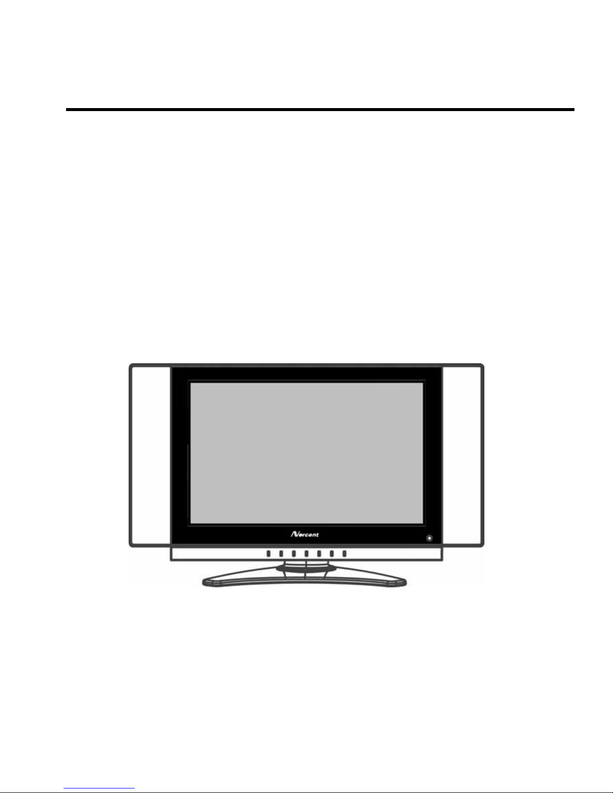
1.2 LCD TV Description
The LCD TV will contain a main board (include audio), a switching power board (include an inverter board), an
IR board, a Headphone jack board and a function keyboard. The main board and power board will house the
flat panel to control logic I
2
C bus, DDC, brightness control logic for LCD panel, DC-DC conversion to supply the
appropriate power to the whole board and transmitting TTL level signals into LCD Module to drive the LCD
display circuit.
The inverter board will drive the 6CCFLs (Cold Cathode Fluorescent Tube).
The function keyboard and Remote Control will provide the OSD control signal to the Main Board.
Apply power to the display by turning the power switch to the "ON" position and allow about ten seconds for
panel warm-up. The Power-On indicator lights "ORANGE" when the display is on.
With proper signals feed to the display, a pattern or data should appear on the screen, adjust the brightness
and contrast to the most pleasing display, or press auto-adjust to get the best picture-quality.
If your TV requires service, it must be returned with the power cord.
1.3 Interface Connectors
(A) AC Power: TV rear side
(B) TV Signal: TV rear side
(C) S-Video (Y/C): TV rear side, 4 Pin Mini-DIN female
(D) Composite Video: TV rear side, RCA female
(E) Composite Video: TV rear side, RCA female
(F) Audio: TV rear side, RCA female (Red/White), right channel/ left channel for Composite Video/ S-Video/
Component Video.
NORCENT LT2022
5
2. Adjustment
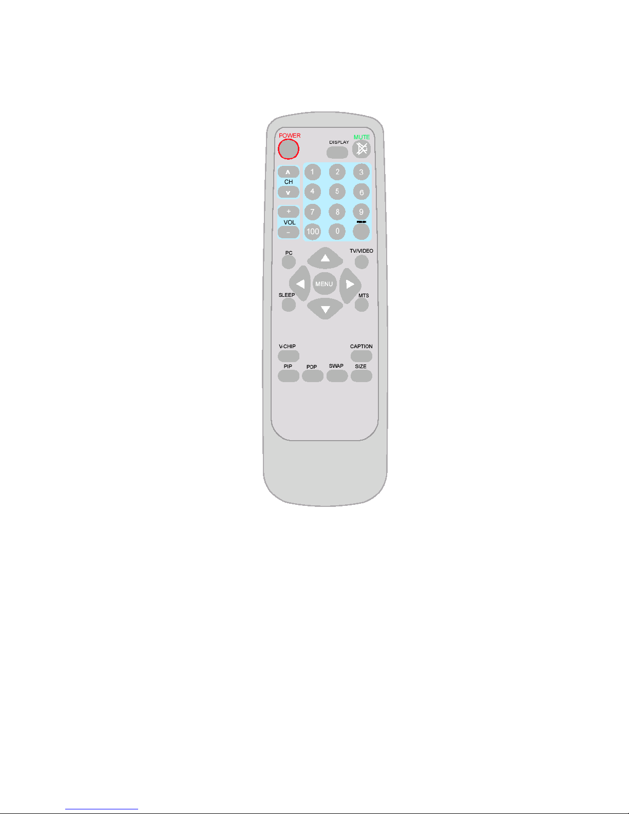
2.1 Use of the Remote Control
POWER:
Press to turn on/off the TV. The
TV is never completely powered
off unless it is physically
unplugged.
0~9/100 Digit buttons
To select a TV channel.
MTS
Press this key to activate
Multichannel Television
Sound, Stereo or Mono
sound.
SLEEP
With this key you can set a time
period after which the TV
should switch itself to standby.
Press the key repeatedly to
select the number of minutes.
This counter runs from 0, 30,
60, 90, 120 minutes. The timer
begins to count down from the
numbers of minutes selected
after the display has
disappeared.
PC
Not supported. (for the
model with this function
only)
MUTE
Temporarily interrupt the
sound or restore it.
DISPLAY
Press this button to Display
Channel number on the
right-top corner.
CH
Press ▲ or▼ to brows
through the TV channels
which are not erased. To
view a blocked channel, use
PRE-CH
Display the previously
selected TV channel.
TV/VIDEO
Select your input source:
press repeatedly to select TV,
AV1, AV2, S-VIDEO or
COMPONENT VIDEO mode,
according to where you
connected your external
source.
AV1/AV2 for a VCR
connected to the AV
connectors of the TV.
S-VIDEO for a S-Video
VCR connected to the SVIDEO connector of the
TV.
COMPONENT for a
DVD/DTV Set Top Box or
another component video
device connected to Y, Pb,
Pr and to the AV AUDIO
inputs L and R.
CAPTION
Press this button to turn
Closed Caption on.
Be sure you have selected
Caption On in the Setup
menu.
MENU
Press repeatedly to
dis
play
OSD menu.
V-CHIP
Press this button to
setu
p p
arental control.
SWAP
Not Supported. (for
the model with this
function only)
SIZE
Not Supported. (for the
model with this function onl
y)
POP
Not Supported. (for the
model with this function
only)
VOL
Press + or – to adjust the
volume.
PIP
Not Supported. (for the
model with this function
only)
NORCENT LT2022
6
2.2 use of the menus
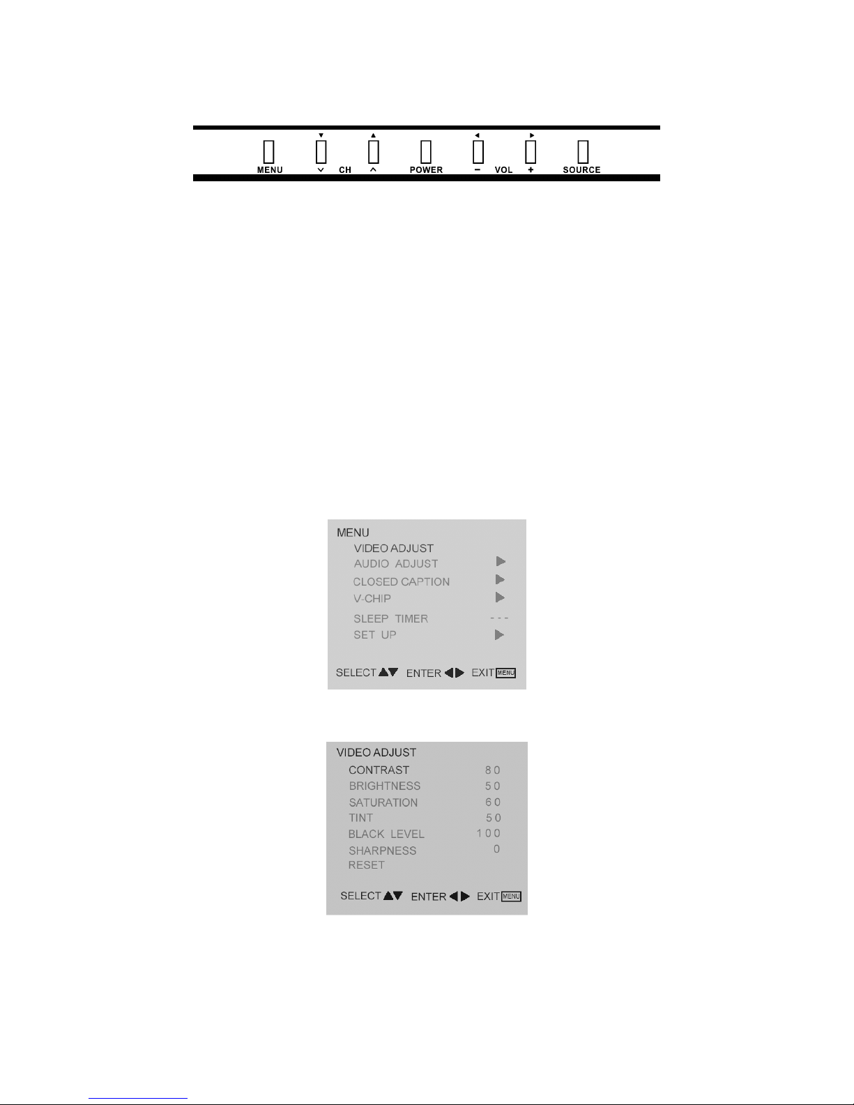
2.2.1 Front Panel Control Knobs
Power Key: Press to turn on or off the TV.
MENU Key: Press to show the OSD menu and exit OSD menu at the TV.
Down / Up Key: Press to perform select function and channel.
- / + Key: Press to confirm your function selection and adjustment.
Source Key: Press to select your input source.
2.2.2 To Use the Menus
1. Press the MENU button to display each menu
2. Use the cursor up/down to select a menu item.
3. Use the cursor left/right to enter a submenu or enable/disable the function.
4. Press the MENU button to exit the menu.
MAIN MENU
Press the MENU button to enter the main OSD (On Screen Display). Adjust items include VIDEO ADJUST,
AUDIO ADJUST, CLOSED CAPTION, V-CHIP, SLEEP TIMER and SET UP
VIDEO ADJUST
1. Contrast, Brightness and Saturation are adjusted from 0 to 100.
2. Tint is adjusted from 0 to 100.
3. Black Level is adjusted from 0 to 100.
4. Sharpness is adjusted from 0 to 10.
You can adjust picture contrast, brightness, color, tint and sharpness to the levels you prefer.
NORCENT LT2022
7
5. Reset is set up to default value.
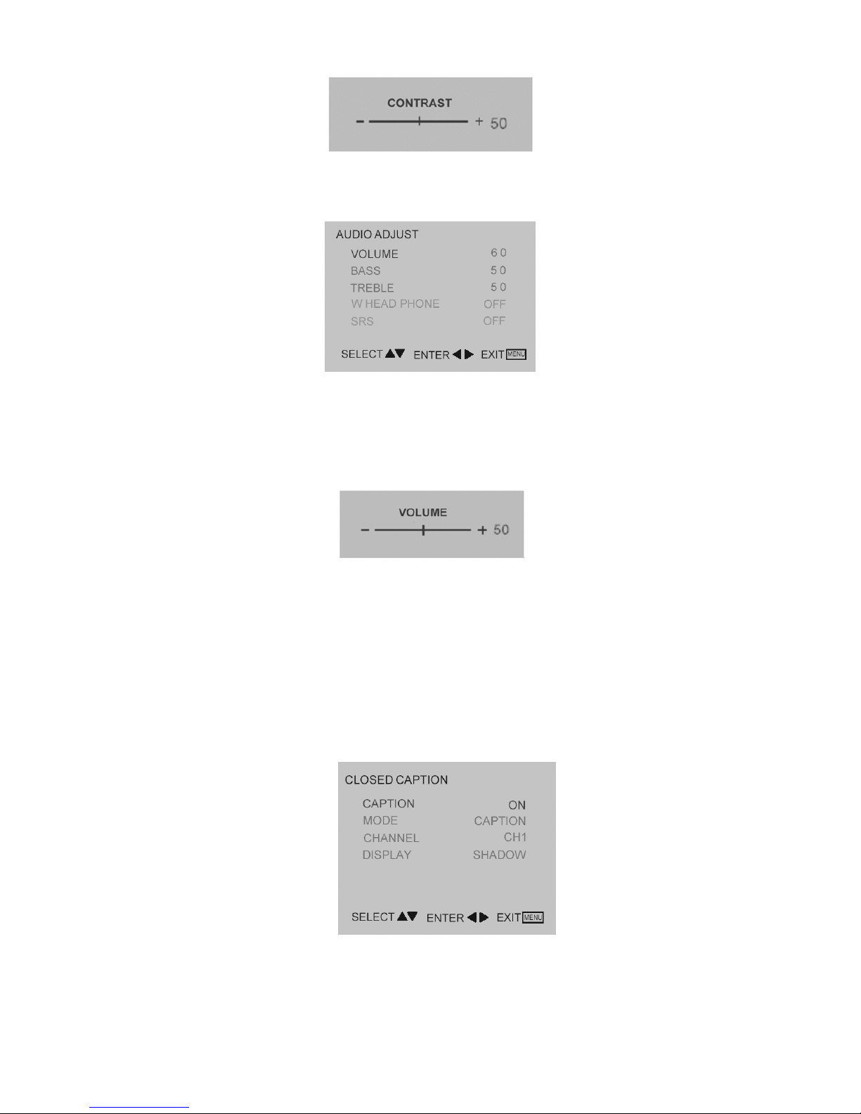
When adjust any item sub-OSD will show up like this
AUDIO ADJUST
1. Volume is adjusted from 0 to 100.
2. Bass and Treble are adjusted from 0 to 100.
3. W-Head Phone (optional) is the function for wireless headphone enable or disable.
You can adjust audio Volume, Balance, Bass and Treble to the levels you prefer.
When adjust any item sub-OSD will show up like this.
CLOSED CAPTION
It’s allows you to read the dialog of television programs on the TV screen. Designed to help the hearing impaired,
this feature uses on screen “text boxes” to show dialogue and conversations while the TV program is in progress.
Captions will appear on the screen only during captioned broadcasts.
Remark: the captions do not always use correct spelling and grammar.
Not all TV programs and product commercials are made for broadcast with Closed Caption information included.
Refer to your area’s TV program listings for the TV channels and times of closed Caption shows. The captioned
programs are usually noted in the TV listings with service Marks such as “CC”.
Caption Mode:
Dialogue (and descriptions) for the action on the captioned TV program shows on screen. Usually CH1 is the most
used channel. CH2 may be used for alternate languages if they are being transmitted.
Text Mode:
Often used for channel guide, schedules, bulletin board information for Closed Caption programs, news, weather
NORCENT LT2022
8
information or stock marker reports. Not all Closed Caption modes are necessarily being use by a TV channel
during the transmission of a Closed Caption program.
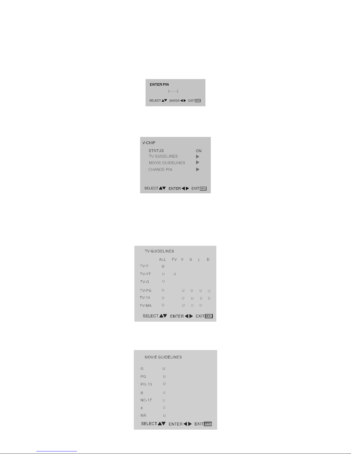
V-CHIP SETUP
Select V-Chip on OSD then enter 4 digits of pin number.
Initial pin number is “0000”.
If you enter an incorrect pin number “Incorrect” message will be displayed.
It is the parental control function (V-chip). It is used to block program viewing based on the ratings by the
broadcaster. The default setting is to allow all programs to be viewed. Viewing can be blocked by the type of
program and by the categories chosen be blocked. It is also possible to block all program viewing for a time period.
A. There are two item could be defined. One is TV Guidelines another one is Movie Guidelines.
B. Setting up TV Guidelines
Use Up/Down arrow buttons to move around the matrix and press Right arrow button to change the
value form “U” to “B” or ”B” to ”U”
U: Unblock
B: Block
C. Setting up Movie Guidelines
Use Up/Down arrow buttons to move around the matrix and press Right arrow button to change the
value from “U” to ‘B” or “B” to “U”
NORCENT LT2022
9
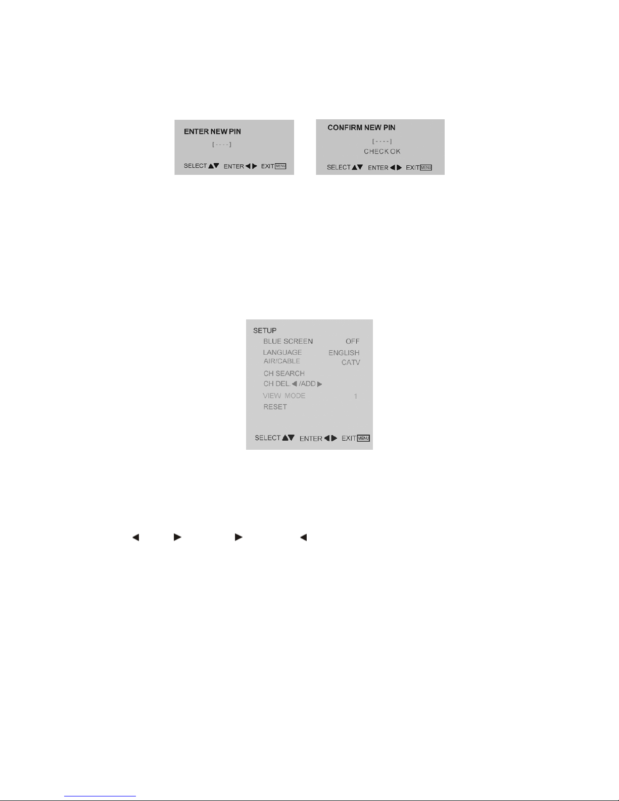
D. CHANGE PIN (personal identification number) is needed for changing password to control V-chip setup.
Process as follows:
1) Enter old pin code
2) Enter new pin code
3) Confirm new pin by entering new pin one more time.
SLEEP TIMER
It is for set a time period after which the TV should switch itself to standby. The counter runs from 0 > 30 > 60 > 90
> 120 minutes.
The timer begins to count down from the number of minutes selected after the display has disappeared.
Note: To view the remaining time, press the SLEEP button once. To cancel the sleep time, repeatedly press the
SLEEP button until… appears. If you turn the TV off after setting the sleep time, the setting will be erased. Set it
again.
SETUP
1. Blue screen for when no video input screen will be blue or blank. If it’s ON, the screen will be in blue. If it’s
OFF, the screen will be blank. Preset is ON.
2. Language for different language OSD MENU includes English / French / Spanish. Preset is English.
3. AIR/CATV/HRC/IRC for different TV input solution, RF and cable.
4. CH Search is for auto memorizes all receiving channels of air TV or CATV programs.
5. CH DEL.
/ADD. is for add “ ” or delete “ “ the current channel for memorizes.
6. RESET is set up to default value.
NORCENT LT2022
10
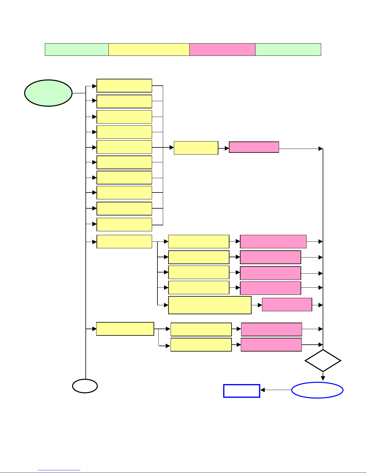
3. Trouble Shooting Chart
Defect Mode Failure Analysis Repair Testing
Completed
NG
Next Step
Missing Line
Bright Dot
Dark Dot
Light Leakage
Mura
Image Sticking
Dot Defect
Brightness Spot
Dot Defect
Particle
Check Panel
Panel Chan
g
e
No display Check Power Board
Check Main board
Check Panel
Change Panel
Change Main board
Change Power Board
Check Keyboard
Change Keyboard
Check Line Connected
Power board and Minored
Change Wires
Noise
Check Main board
Check Panel
Change Main board
Change Panel
A
Abnormal
Display
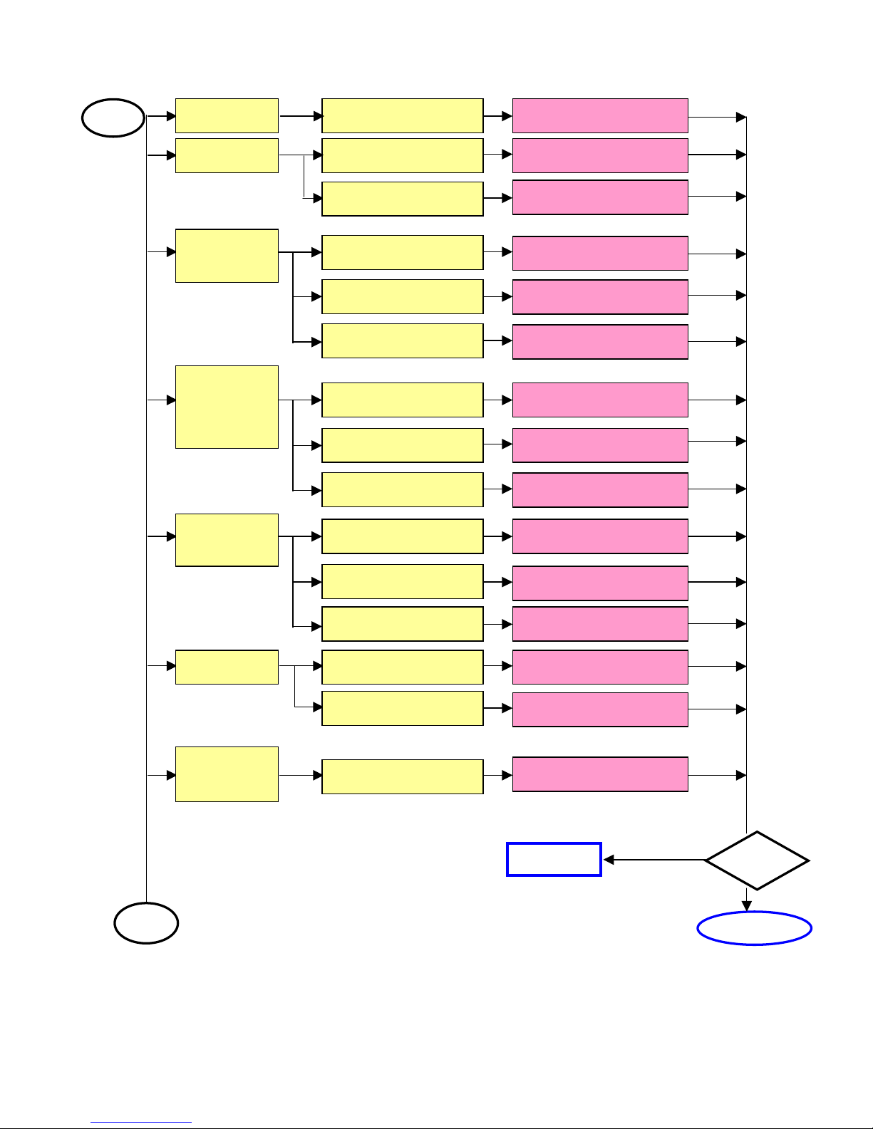
NORCENT LT2022
11
Test
Complete
A
Next Step
A
Noise Check Single Cable Change Single Cable
Flicker Check Main board Change Main board
Check Panel
Change Panel
Abnormal
Gray
Check Main board
Change Main board
Check Panel
Change Panel
Check LVD Cable
Change LVDS Cable
R\G\B
Display
Abnormal
Check Single Cable Change Single Cable
Check Main board Change Main board
Check Panel
Change Panel
Monitor
Shut Down
Check Power board Change Power board
Check Keyboard Change Keyboard
Check Main board
Change Main board
No signal Check Single Cable Change Single Cable
Check Main board
Change Main board
Power on
Display
A
bnormal
Check Main board
Change Main board
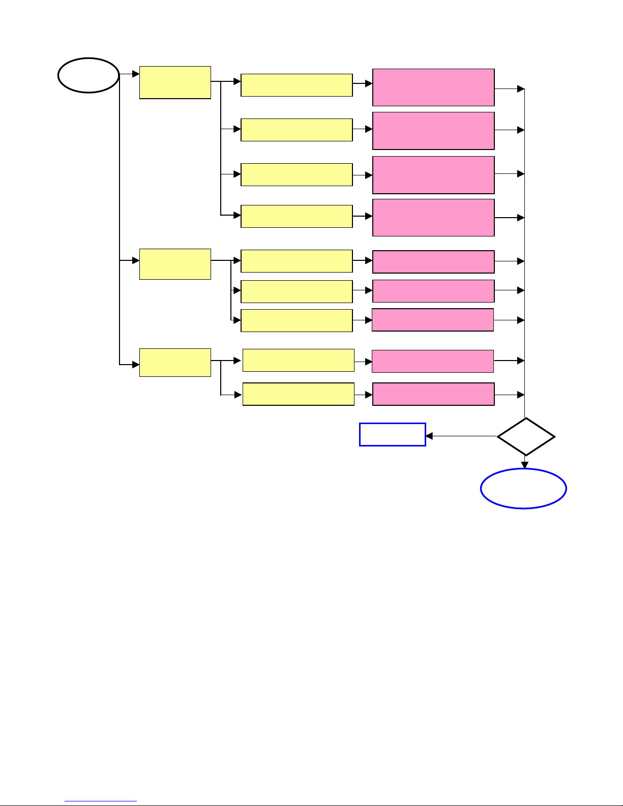
NORCENT LT2022
12
Change Keyboard or
Main board
Change Keyboard or
Main board or wire
Change Keyboard
Change Main board
Change Main board
Change LVDS Wire
LED Off
Change Keyboard or
Main board or wire
Change Keyboard or
Main board or wire
A
Change Wires
LED Abnormal
LED Dark
LED Display
Abnormal
LED Flicker
Abnormal
Keyboard
Check Wires
Check Keyboard
Check Main board
Abnormal
OSD
Check Main board
Check LVDS Wire
Test
Next step
Completed
NORCENT LT2022
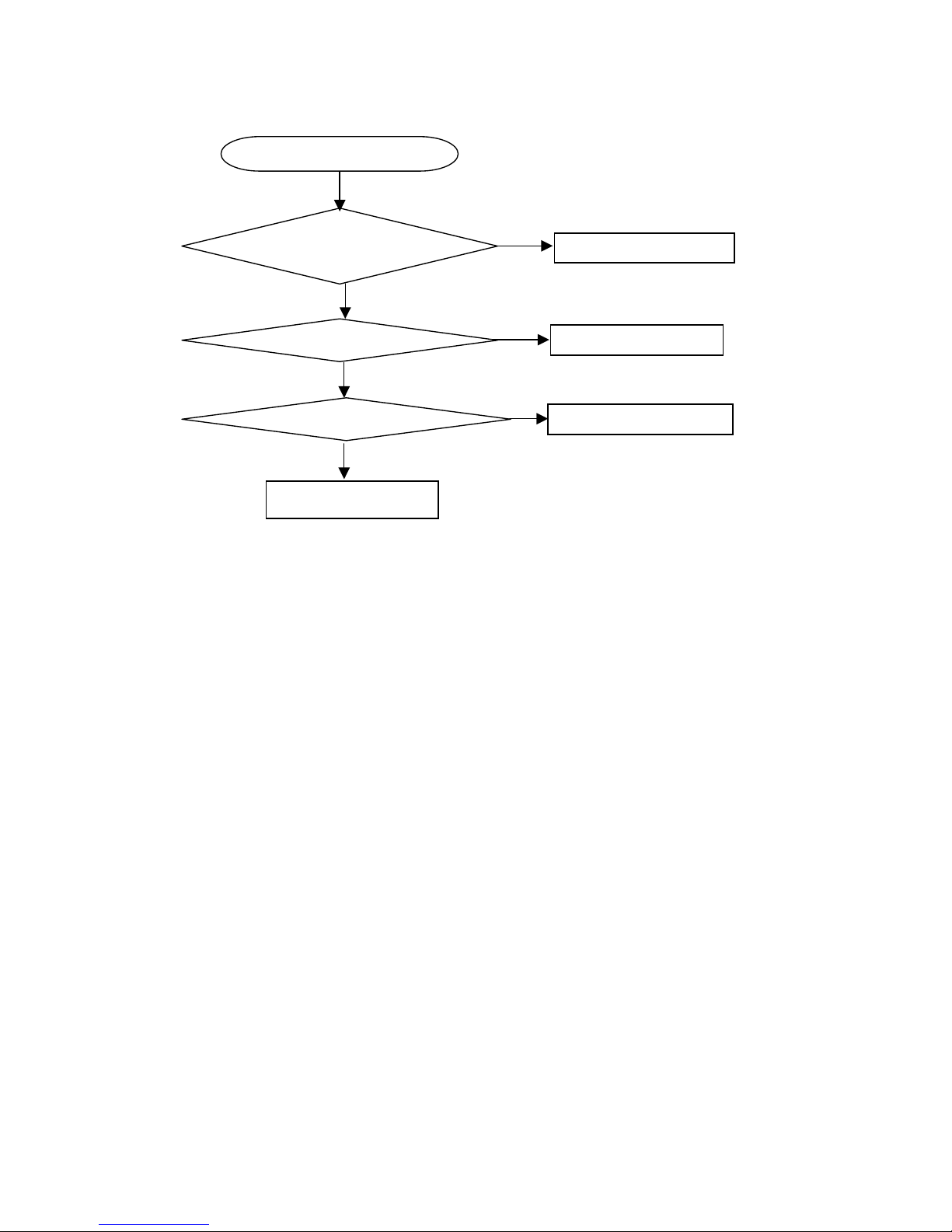
13
Key Board
OSD is unstable or not working
Is Key Pad Board connecting normally?
Connect Key Pad Board
Is Button Switch normally?
Replace Button Switch
Y
N
N
Is Key Pad Board Normally?
Replace Key Pad Board
Y
N
Y
Check Main Board

NORCENT LT2022
14
4. White-Balance, Luminance adjustment
Approximately 30 minutes should be allowed for warming up before proceeding white balance adjustment.
Before started adjust white balance, please setting the Chroma-7120 MEM. Channel 1 to 9300 color. (Our
9300 parameter is x =283, y = 297, Y> 350cd/cm2 (TV Mode))
For setting MEM. channel, you can refer to Chroma-7120 user guide or simple use “Mode”, “SC” and “NEXT”
key to modify XyY value and use “ID” key to modify the TEXT description
Following is the procedure to do white-balance adjust
When the monitor is in ON status, press Number key 100 9 9 9 will enter the factory mode, and OSD
will be shown in the screen, then select MORE function will into Bias and Gain adjustment.
SCALER Adjustment:
CO, BR Contrast and Brightness adjust.
RG, GG, BG R, G, B Gain adjust.
RB, GB, BB R, G, B Bias adjust.
S9, S6, ST, SH Save 9300, 6500, TV/AV /S-Video /480i, Component 480P color temperature.
R9, R6, RT, RH Recall 9300, 6500, TV/AV /S-Video /480i, Component 480P color temperature.
CC Set Close Caption ON/OFF.
VC Set V Chip ON/OFF.
WH Set Wireless Headphone ON/OFF.
PP Set PIP ON/OFF.
BI Setup Burn-in mode ON / OFF.
ISP Set ISP ON/OFF.
SR PP Set SRS ON/OFF.
EX Exit MORE function to factory mode menu.
Before Adjustment:
1. Press Number key 100 9 9 1 into Engineer Mode.
2. Press menu key repeat to “ADC “page, then select “EPinit” and press “right” key to initial EEPROM.
3. Press Number key 100 9 9 9 into the Factory Mode.
Gain adjustment:
Adjust Video color-temperature:
1. Switch the chroma-7120 to RGB-mode (with press “MODE” button)
2. Switch the MEM. Channel to Channel 03 (with up or down arrow on Chroma-7120)
3. The lcd-indicator on chroma-7120 will show R = ***, G=***, B=***.
4. Change source input to AV1.
5. Adjust the GG up to G value at chroma-7120 not going up, set the G value is max.
6. Adjust the BG and RG till the value of R and B value on Chroma-7120 same as G value.
7. Repeat the item 4 and 5 to make the R, G, B value are the same.
8. Select cursor to “ST” and press “right” arrow to save the value.
Turn the POWER-button off to on to quit from factory mode.
Remark: 1. Auto Level of PC should be adjusted with TIMG 127, PATN 42 or 16 GRAYS screen.
2. Auto Level of Component should be adjusted with 16 GRAYS screen.
3. It should be under white picture while adjusting the color temperature of all display modes.
NORCENT LT2022
15
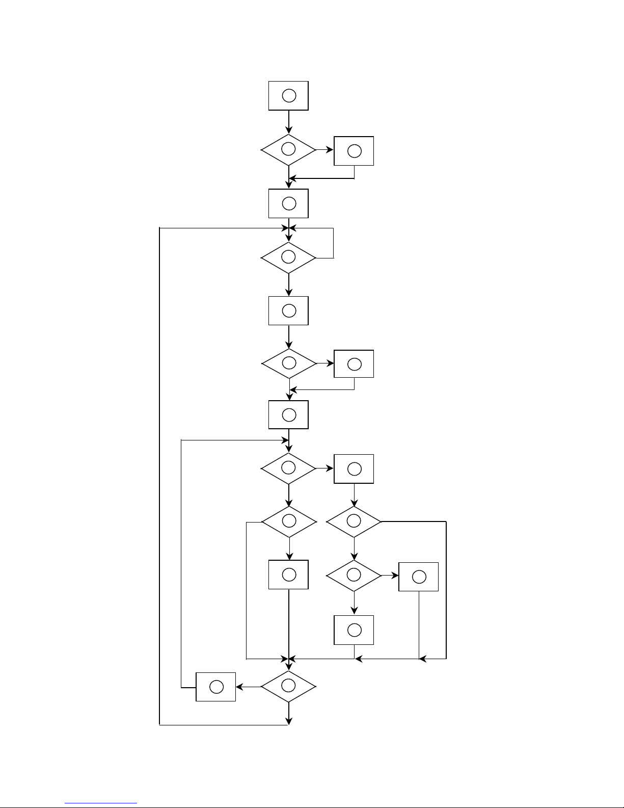
5. Software Flow Chart
1
2
N
Y
5
Y
N
10
Y
N
12
Y
N
7
Y
N
6
4
3
8
9
14
11
13
Y
N
15
Y
N
16
17
19
Y
N
18

NORCENT LT2022
16
1) MCU initializes.
2) Is the EEPROM blank?
3) Program the EEPROM by default values.
4) Get the PWM value of brightness from EEPROM.
5) Is the power key pressed?
6) Clear all global flags.
7) Are the AUTO and SELECT keys pressed?
8) Enter factory mode.
9) Save the power key status into EEPROM.
Turn on the LED and set it to green color.
Scalar initializes.
10) In standby mode?
11) Update the lifetime of back light.
12) Check the analog port, are they’re any signals coming?
13) Does the scalar send out an interrupt request?
14) Wake up the scalar.
15) Are there any signals coming from analog port?
16) Display "No connection Check Signal Cable" message. And go into standby mode after the message
disappears.
17) Program the scalar to be able to show the coming mode.
18) Process the OSD display.
19) Read the keyboard. Is the power key pressed?
NORCENT LT2022
17
6. BOM
EA64MSNKB2NCPVC
Location Part No. for TPV Description Quantity Unit
M1V 330 4128 SCREW M3X4 2 PCS
CBPFA64KMSE1P CONVERSION BOARD 1 PCS
PWTV2062CM1 20" POWER BOARD ASS'Y 1 PCS
1V6012 1 SCREW 2 PCS
15T5943 6 MAIN FRAME 1 PCS
15T8024 1 AC-SOCKET 1 PCS
15V5930 1 BKT CONNECTOR 1 PCS
15V6163 1 BKT D-SUB 1 PCS
26T 800504 5 BAR CODE 1 PCS
34V1223EGN 3L COVER HINGE 1 PCS
34V1224 GM L COVER CABLE 1 PCS
40T 200815 6B ID LABEL 1 PCS
40T 58160811A GREEN LEBEL 1 PCS
40T 58162435A LABEL 1 PCS
40T 583 11 1B I/D LABEL 1 PCS
40T 583 12 I/O LABEL 1 PCS
41T2001815 7A MANUAL 1 PCS
41T780081527A WARRANTY CARD 1 PCS
41T780081528A QSG 1 PCS
44T2004 1 EPS 1 PCS
44T2004 2 EPS 1 PCS
44T2004 5 1A U TYPE SHEET FOR BASE 1 PCS
44T2004815 2A CARTON 1 PCS
44T3231 15 EVA WASHER 1 PCS
44T3231 15528 EVA WASHER 1 PCS
44T3231 15548 EVA WASHER 1 PCS
44TZ001200 4 PIZZA BOX 1 PCS
45T 76 28 RN PE BAG FOR MANUAL 1 PCS
45T 88606 2 PE BAG FOR BASE 1 PCS
45T 88609 22 EPE COVER 1 PCS
45T 88626 3 PE BAG FOR MONITOR 1 PCS
52T 1185 MIDDLE TAPE FOR CARTON 180 CM
52T 1186 SMALL TAPE 10 CM
52T 1210 A ALUMINIUM TAPE 4 PCS
52T 1211 A ADHESIVE TYPE 1 PCS
52T 1211 B ADHESIVE TYPE 2 PCS
52T6020 6 PROTECT FILM 1 PCS
52T6025 11676 INSULATE SHEET 1 PCS
71T 100521 CORE 1 PCS
85T 583501504 GASKET 3 PCS
85V 650 3 SHIELD 1 PCS
85V 653 1 SHIELD CONNETDR 1 PCS
89T176J 50502 FFC CABLE 1 PCS
89T402A18N IS POWER CORD 1 PCS
92TB1JX1A31GF BATTERY 2 PCS
98TR7SW3NENCF Remote Control 1 PCS
M1V 140 12120 SCREW 6 PCS
M1V 330 4120 SCREW 1 PCS
M1V 330 4128 SCREW M3X4 2 PCS
M1V 330 4128 SCREW M3X4 3 PCS
M1V 330 4128 SCREW M3X4 1 PCS
M1V 330 6128 SCREW 1 PCS
NORCENT LT2022
18
M1V 330 6128 SCREW 1 PCS
M1V1030 14128 SCREW 3X14mm 4 PCS
M1V1130 6128 SCREW 8 PCS
M1V1130 6128 SCREW 4 PCS
M1V1140 4128 SCREW 4X6 1 PCS
Q1V 330 12120 SCREW 3X12mm 5 PCS
Q1V 930 6128 SCREW (T3X6) 3 PCS
Q1V1030 12128 SCREW 8 PCS
705LA64FB34044 20"TV BACK COVER ASS'Y 1 PCS
E750L 750TVMA1T01 1 E CMO 20.1"NORCENT CONSIG 1 PCS
HJPFA60A1 HEADPHONE JACK BOARD 1 PCS
IRPFF91A3 LCD TV IR BOARD 1 PCS
KEPFA60KA11 KEY BOARD 1 PCS
12T 394 3 RUBBER FOOT 6 PCS
15V5939 1 BKT BASE 1 PCS
33T4757 AI D BUTTON CHIN 1 PCS
33V4659 1 C LENS REMOTE 1 PCS
34T1222 GM 5A REAR COVER 1 PCS
34T1399 GM A COVER CHIN2 1 PCS
34V1225 GN L LOVER STAND B 1 PCS
34V1226 GN L STAND 1 PCS
34V1284 GN L LOVER STAND F 1 PCS
36T 700 2 GN SPR GRILL 2 PCS
95T8014 5543 WIRE HARNESS 1 PCS
95T8014 8564 HARNESS 8P -8P+4P 660MM 1 PCS
Q1V 130 8120 SCREW 10 PCS
Q1V 140 20120 SCREW 4 PCS
Q1V 330 8120 SCREW 3X8mm 4 PCS
Q1V 330 8120 SCREW 3X8mm 2 PCS
Q1V 330 8120 SCREW 3X8mm 2 PCS
Q1V1030 8128 SCREW 8 PCS
Q1V1030 8128 SCREW 2 PCS
Q1V1030 12128 SCREW 3 PCS
B34T1397DGN10A BEZEL-20-A2 1 PCS
T34T1377 GN L BASE-S2 1 PCS
E078L S78T3236L SPEAKER ASS'Y 1 PCS
E078R S78T3236R SPEAKER ASS'Y 1 PCS
M037 S37T4821 ACER 20" TV HINGE ASS'Y 1 PCS
HJPFA60A1
SMTHJPFA60A1 HEADPHONE BOARD FOR SMT 1 PCS
95T 900 53 HARNESS 95MM 1 PCS
CN1 33T3802 5H WAFER 5P RIGHT ANELE PI 1 PCS
J1 88V 302 7T PHONE JACK 1 PCS
715V1290 2 HEAD PHONE JACK BOARD 1 PCS
C1 65T0603102 32 CHIP 1000PF 50V X7R 1 PCS
C2 65T0603102 32 CHIP 1000PF 50V X7R 1 PCS
FB1 71T 56U601 BEAD 600 OHM 1 PCS
FB2 71T 56U601 BEAD 600 OHM 1 PCS
FB3 71T 56U601 BEAD 600 OHM 1 PCS
FB4 71T 56U601 BEAD 600 OHM 1 PCS
IRPFF91A3
SMTIRPFF91A3 TUNER BOARD SMT 1 PCS
95T 900 53 HARNESS 95MM 1 PCS
D600 56T 627 7 FM-6038TM2-5AN 1 PCS
J1 33T3802 4 WAFER PH-4 1 PCS
715V1108 1B ir led board 1 PCS
C600 65T0603101 31 CHIP 100PF 50V NPO 1 PCS
NORCENT LT2022
19
C601 65T0603104 32 CHIP 0.1UF 50V X7R 1 PCS
C602 65T0603104 32 CHIP 0.1UF 50V X7R 1 PCS
FB1 71T 59B601 EA CHIP BEAD 600OHM 0603 T 1 PCS
FB3 71T 59B601 EA CHIP BEAD 600OHM 0603 T 1 PCS
R600 61V0603101 CHIPR 100 OHM+-5% 1/10W 1 PCS
KEPFA60KA11
SMTKEPFA60KA11 TUNER BOARD SMT 1 PCS
95T 900 59 WIRE HARNESS 1 PCS
CN1 33T3802 8H WAFER 8P RIGHT ANGLE PI 1 PCS
D2 81T 12 2 GP GP36032ME/50-ZO 1 PCS
S1 77T 600 1GCJ TACT SWITCH TSPB-2-NP 1 PCS
S2 77T 600 1GCJ TACT SWITCH TSPB-2-NP 1 PCS
S3 77T 600 1GCJ TACT SWITCH TSPB-2-NP 1 PCS
S4 77T 600 1GCJ TACT SWITCH TSPB-2-NP 1 PCS
S5 77T 600 1GCJ TACT SWITCH TSPB-2-NP 1 PCS
S6 77T 600 1GCJ TACT SWITCH TSPB-2-NP 1 PCS
S7 77T 600 1GCJ TACT SWITCH TSPB-2-NP 1 PCS
715V1328 1 2 KEPC 1 PCS
C1 65T0603104 32 CHIP 0.1UF 50V X7R 1 PCS
C2 65T0603104 32 CHIP 0.1UF 50V X7R 1 PCS
C5 65T0603104 32 CHIP 0.1UF 50V X7R 1 PCS
FB1 71T 56U601 BEAD 600 OHM 1 PCS
FB3 71T 56U601 BEAD 600 OHM 1 PCS
FB5 71T 56U601 BEAD 600 OHM 1 PCS
Q2 57T 417 6 PMBS3906/PHILIPS-SMT 1 PCS
R2 61V0603100 1F CHIP 1KOHM 1/10W 1% 1 PCS
R20 61V0603301 CHIP 300 OHM 1/16W 1 PCS
R3 61V0603150 1F CHIP 1.5OHM 1/10W 1% 1 PCS
R4 61V0603180 1F CHIP 1.8K OHM 1/16W 1% 1 PCS
R5 61V0603220 1F 2.2K OHM 1% 1/10W 1 PCS
R6 61V0603360 1F CHIP 3.6KOHM 1% 1/10W 1 PCS
R7 61V0603470 1F CHIP 4.7K OHM 1/16W 1% 1 PCS
R8 61V0603103 CHIPR 10K OHM+-5% 1/10W 1 PCS
R9 61V0603103 CHIPR 10K OHM+-5% 1/10W 1 PCS
44F3231 20020 EVA 1 PCS
51F 300110 1 WD2102 4 G
33F303H03P H PH-3 1 PCS
33F303T020 PH PH-T 2 PCS
34F6205 1 BACK COVER 1 PCS
71FW100001006 6.5*4.5*10+H/S 2 PCS
44F3231 20020 EVA 1 PCS
51F 300110 1 WD2102 4 G
78FS803 1 KD
8 欧 3W YD40-1A-G
2 PCS
33F303H02P H PH-2 1 PCS
33F303T020 PH PH-T 2 PCS
34F6205 2 BACK COVER 1 PCS
71FW100001006 6.5*4.5*10+H/S 2 PCS
78FS323 1
90*40*15.35 8 欧 3W9040C0
1 PCS
2F0806100 SCREW NUTS 3 PCS
4F0815052 00 WASHER 9 PCS
4F081510M 00 WASHER 4 PCS
4F081510T 00 WASHER 8 PCS
15F 482110 BRACKET SECC 2.0 1 PCS
15F 482120 BRACKET SECC 2.0 1 PCS
15F 482130 BRACKET SUS430 1 PCS
19F0522140 SPRING 2 PCS
19F25214L0 SPRING 1 PCS
 Loading...