

Page 1
Service Manual for L1 and L2
Nokia Lumia 820
RM-824, RM-825
Key features
Windows Phone 8
1.5 GHz dual-core processor (Qualcomm Snapdragon S4)
8 GB internal flash memory, MicroSD card slot
EGSM, WCDMA HSPA and 4G LTE
Near Field Communication (NFC) technology
Wireless charging (Qi standard) available with an accessory
(Wireless Charging Shell for Lumia 820)
Version 1.0
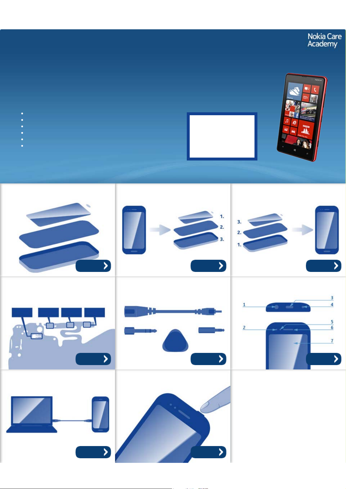
Exploded view Disassembly steps Assembly hints
Check the repair
policy before
performing any
mechanical repair
on Service Level
1&2!
More More More
Solder components Service devices Product controls and interfaces
More More More
Service concept Phone reset
More More
©2012 Nokia | Nokia Internal Use only | All Rights Reserved.
Page 2
Service Manual Level 1 and 2
Nokia Lumia 820
RM-824, RM-825
Version 1.0
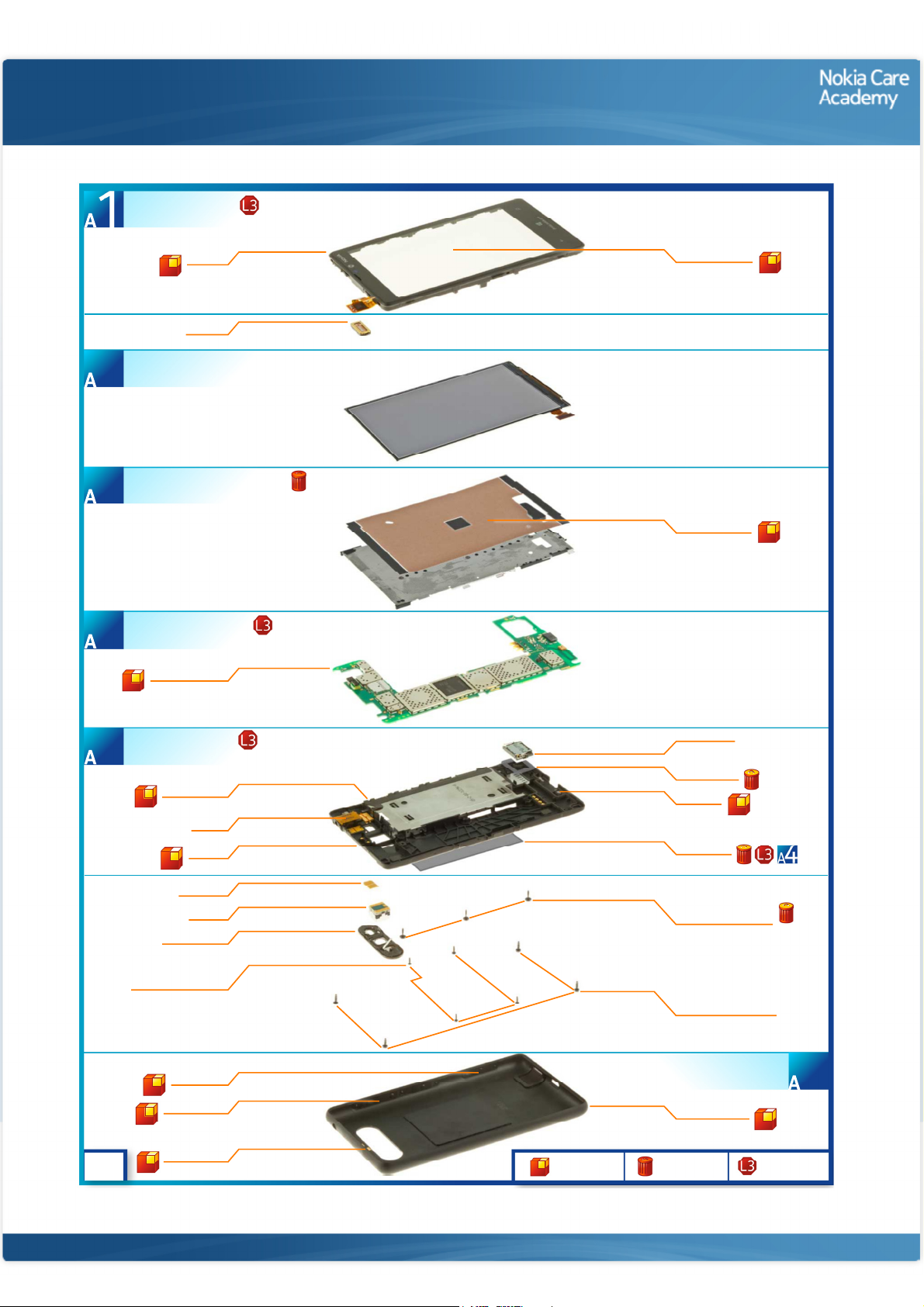
A-COVER ASSEMBLY
(I0001 - I0002)
Exploded view
A-COVER
I0002
EARPIECE
I0003
DISPLAY
2
DISPLAY SUPPORT ASSEMBLY
(I0004)
3
LIGHT SWAP PACKAGE
(I0005 - I0006)
4
LIGHT SWAP PWB
I0005
TOUCH WINDOW
I0001
HEAT SPREADER
I0004
CHASSIS ASSEMBLY
(I0007 - I0012)
5
SCREW TORX+ SIZE 4
v1.0
SIDE KEY FLEX
I0010
AV FLEX
I0009
CHASSIS
I0011
LED FLASH
I0014
CAMERA
I0022
CAMERA DECO
I0013
RF1.0 x 3.5
I0017
CAMERA KEY
I0019
VOLUME KEYS
I0018
NFC ANTENNA
I0021
Only available
as assembly
IHF SPEAKER
I0007
IHF ADHESIVE
I0008
ANTENNA
I0012
TYPE LABEL
I0006
SCREW TORX+ SIZE 4
M1.0 X 4.8
I0015
SCREW TORX+ SIZE 4
RF1.4 X 4.8
I0016
BATTERY COVER ASSEMBLY
Not reuseable
after removal
(I0018 - I0021)
BATTERY COVER
I0020
Repair/swap
only in level 3
6
©2012 Nokia | Nokia Internal Use only | All Rights Reserved.
Page 3
Service Manual Level 1 and 2
Nokia Lumia 820
RM- 824, RM-825
Version 1.0
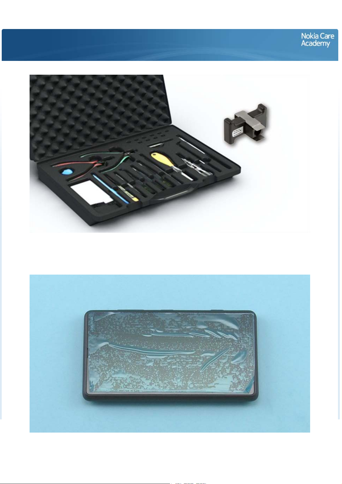
Disassembly steps
For disassembling you need the Nokia Standard toolkit version 2. You will also need the camera removal
tool SS-210. If the device is brought to service due to problems with NFC or wireless charging, please
collect the BATTERY COVER as well.
Before starting the disassembly, make sure that the device is powered off. Protect the TOUCH WINDOW
with protective film.
Page 4
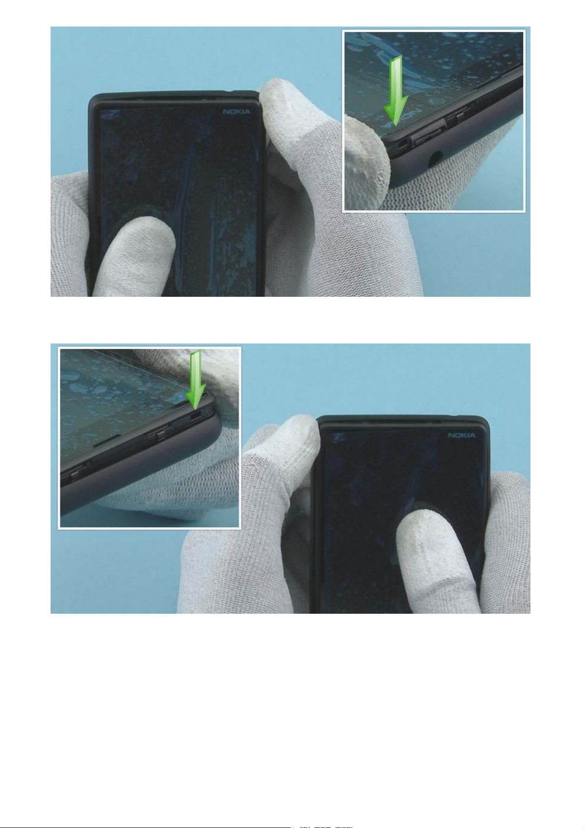
Start releasing the BATTERY COVER by pushing down the top right corner.
Then release the top left corner so that the main body comes out of the BATTERY COVER ASSEMBLY.
Page 5
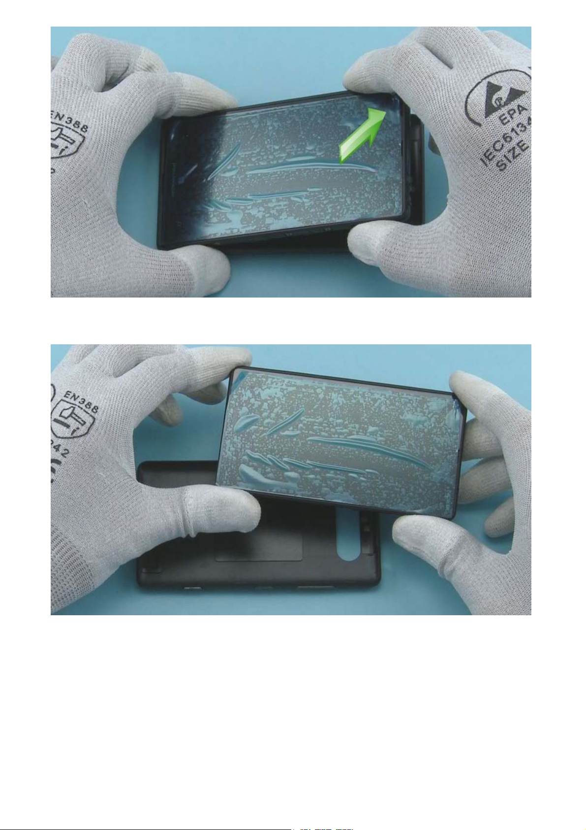
Lift up the main body from the bottom end.
The BATTERY COVER can now be separated from the main body.
Page 6
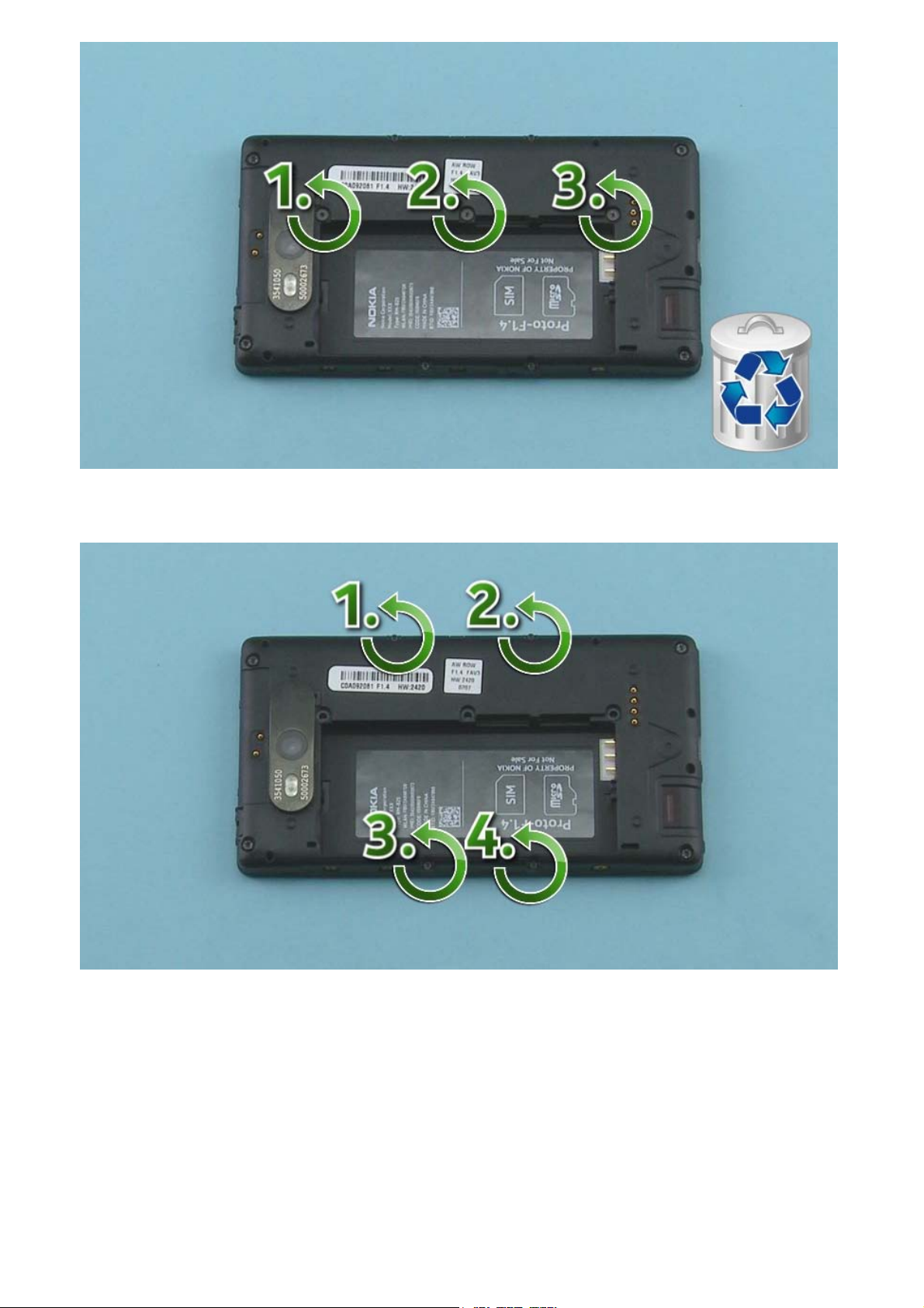
Unscrew the three TORX+ size 4 screws in the order shown. Do not use them again. Discard them.
Unscrew the four TORX+ size 4 screws in the order shown.
Page 7
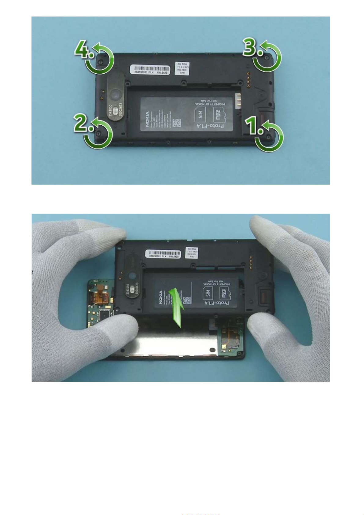
Unscrew the four TORX+ size 4 screws in the order shown.
Lift up and remove the CHASSIS ASSEMBLY.
Page 8
Remove the CAMERA by using the camera removal tool SS-210. First place the SS-210 on top of the
CAMERA. Press down carefully the black plastic parts of the SS-210. And then press down the metal
sheets until the camera retaining clips are released.
Grab the sides of the SS-210 and lift up to remove the CAMERA.
Page 9
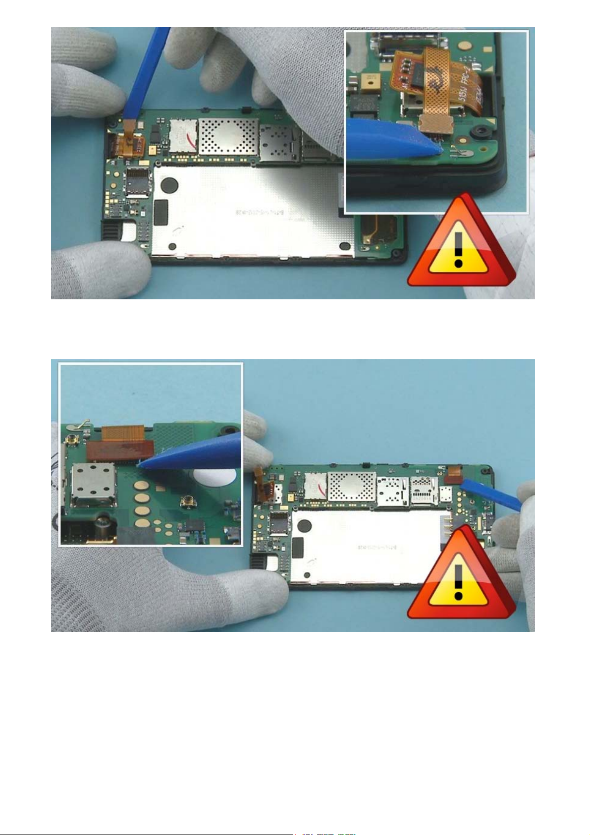
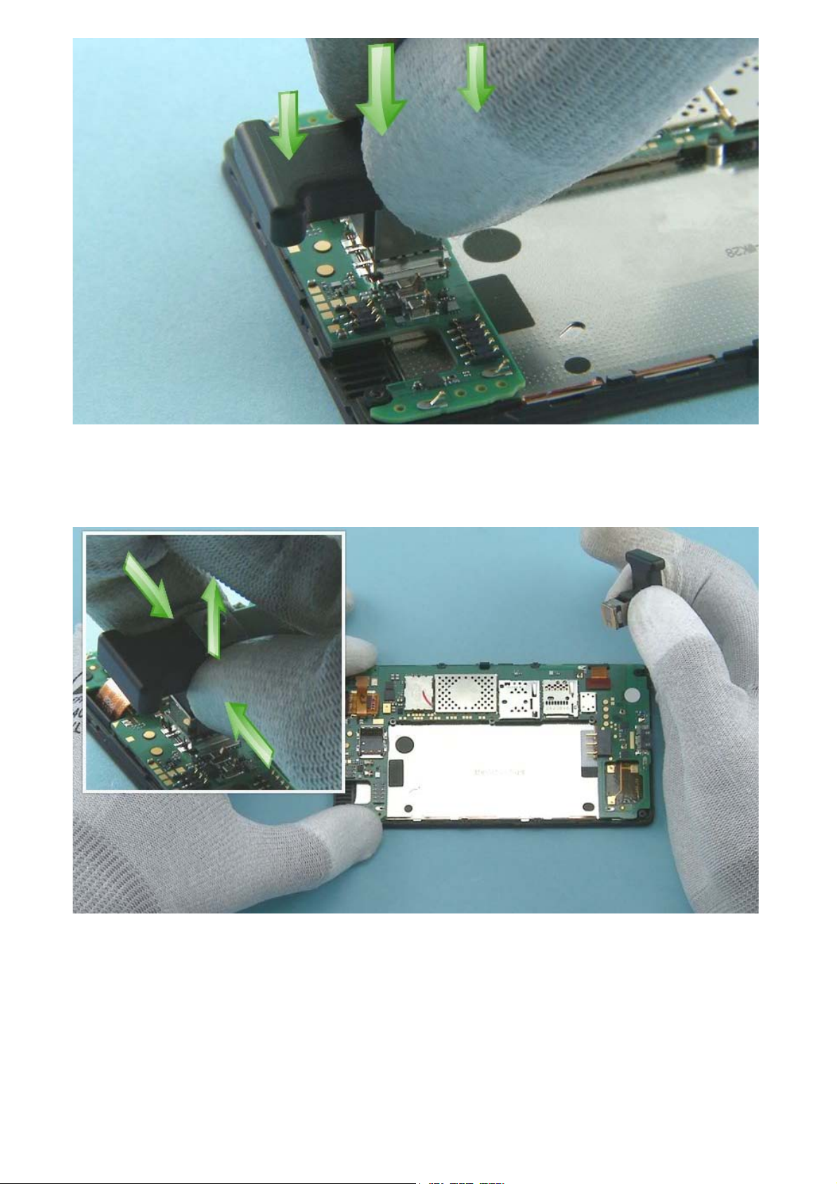
Open the TOUCH CONNECTOR with the SS-93. Be careful not to damage the connector or any nearby
components.
Use the SS-93 to open the DISPLAY CONNECTOR. Be careful not to damage the connector or any nearby
components.
Page 10
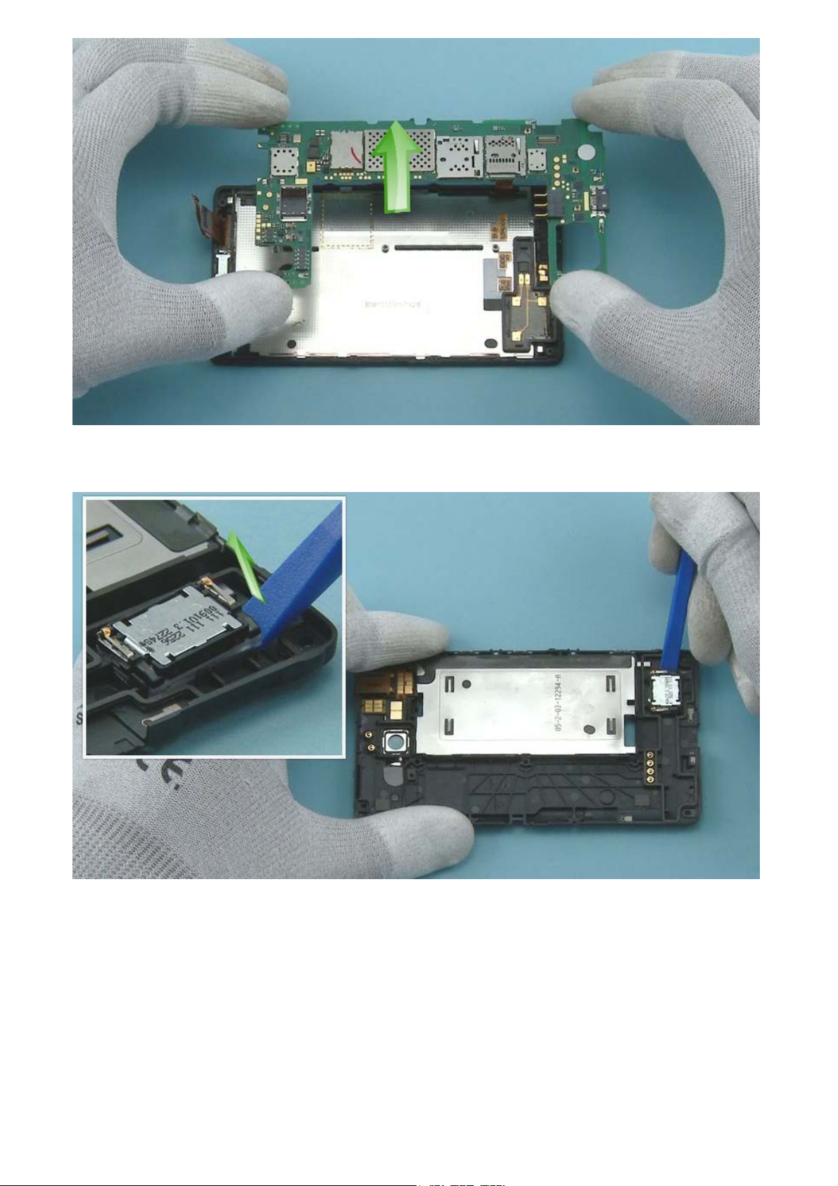
The ENGINE BOARD can now be lifted up.
Use the SS-93 to lever out the IHF SPEAKER.
Page 11

Use tweezers to remove the IHF SPEAKER.
Remove and discard the adhesive remains from the speaker slot.
Page 12

Use tweezers to remove the EARPIECE.
To separate the A-COVER and the DISPLAY, release the three shown clips.
Page 13

Release also the clips from the other side.
Carefully lever out the DISPLAY with the SS-93.
Page 14

Lift up and remove the DISPLAY.
Protect the DISPLAY with protective film.
Page 15

Use the SS-93 to detach the CAMERA DECO.
Remove the CAMERA DECO.
Page 16

Make sure the adhesive residue is removed.
Release the LED FLASH from the CAMERA DECO with the SS-93 and remove it with tweezers.
Page 17

The Nokia Lumia 820 disassembly procedure is complete.
-END OF DISASSEMBLY-
©2012 Nokia | Nokia Internal Use only | All Rights Reserved.
Page 18

Service Manual Level 1 and 2
Nokia Lumia 820
RM- 824, RM-825
Version 1.0
Assembly steps
For assembling you need the Nokia Standard toolkit version 2.
Place the LED FLASH to the CAMERA DECO with tweezers.
Page 19

Gently press the LED FLASH to activate the adhesive.
Place the CAMERA DECO to the CHASSIS and press down to activate the adhesive.
Page 20

Check from the other side of the CHASSIS that the clip holding the CAMERA DECO is attached.
When assembling the EARPIECE, make sure it is correctly aligned and the shown pins are facing the right
way.
Page 21

When assembling the IHF SPEAKER, make sure it is correctly aligned and the shown pins are facing the
right way.
Remove the protective film from the DISPLAY. Place the top end of the DISPLAY to the A-COVER as
shown.
Page 22

Lower down the bottom end of the DISPLAY and press it gently.
Remove the remaining protective film from the HEAT SPREADER. Place the top end of the DISPLAY
SUPPORT to the A-COVER as shown.
Page 23

Lower down the bottom end of the DISPLAY SUPPORT and press it gently.
Fasten the four TORX+ size 4 screws in the order shown to the torque of 6 Ncm.
Page 24

Fasten the four TORX+ size 4 screws in the order shown to the torque of 6 Ncm.
Fasten the four TORX+ size 4 screws in the order shown to the torque of 13 Ncm.
©2012 Nokia | Nokia Internal Use only | All Rights Reserved.
Page 25

Service Manual Level 1 and 2
Nokia Lumia 820
RM-824, RM-825
Version 1.0
Solder components
X1302
LED
spring
X1301
LED
spring
X1303
LED
GND spring
MIMO Antenna
GND spring
LED
Fuse
X2161
Speaker
spring
X2162
Speaker
spring
Camera
fuse
F1400 X1000F1300
Grounding
spring
X1001X7810
Grounding
spring
BOTTOM
MIMO Antenna
spring
Micro USB
connector
X3300
MIMO Antenna
GND spring
X7811X7804
Main antenna
spring
Battery
connector
X2002
Sidekey
connector
X4400
LED flash
GND spring
LED flash
spring
Grounding
X1471
RTC
Capacitor
spring
X1002
BT/WLAN
GND springAVConnector
X6301
X2160
X1400G4200 X7800X7809
GPS
GND spring
Camera
socket
©2012 Nokia | Confidential | All Rights Reserved.
Page 26

Service Manual Level 1 and 2
V
0
Nokia Lumia 820
RM-824, RM-825
ersion 1.
CA-101 Service cable AC-50 USB charger BP-5T
Service devices
SS-210 Camera removal tool Nokia Standard Toolkit (v2)
For more information, refer to the Service
Bulletin (SB-011) on Nokia Online. Supplier or
manufacturer contacts for tool re-order can be
found in “Recommended service equipment”
document on Nokia Online.
©2012 Nokia | Nokia Internal Use only | All Rights Reserved.
Page 27

Service Manual Level 1 and 2
Nokia Lumia 820
RM-824, RM-825
Version 1.0
Product controls and interfaces
2
4
6
9
10
11
1
1 — 3.5 mm universal audio
connector
2 — Earpiece
3
3 — Front camera
4 — Ambient light & Proximity
sensors
5 — Touch screen
6 — Back key
5
7 — Start key
8 — Search key
9 — Microphone
10 — Micro USB connector
7
8
11 — Loudspeaker
12 — Camera
13 — Camera flash
14 — Volume keys
15 — Power/Lock key
12
13
16 — Camera key
14
15
16
Ver. 1.0
©2012 Nokia | Nokia Internal Use only | All Rights Reserved.
Page 28

Service Manual Level 1 and 2
Nokia Lumia 820
RM-824, RM-825
Version 1.0
Flashing concept
Service concept
Service
software
CA-101
Care Dummy Battery
with power supply
via Nokia charger
or product
specific battery
Transceiver
©2012 Nokia | Nokia Internal Use only | All Rights Reserved.
Page 29

Service Manual Level 1 and 2
Nokia Lumia 820
RM- 824, RM-825
Version 1.0
Phone reset
Hardware reset
If the phone hardware is jammed, you should first
recommend that the consumer performs a hardware reset.
The hardware reset does not reset the Windows Live ID or
remove any consumer data.
To perform a hardware reset remove the battery and
reinsert it. Boot up the phone normally.
Software / operating system (OS) reset
The software / operating system (OS) reset returns the phone to its out-of-the-box state. Note that
this procedure erases all consumer data! Always first try to perform a hardware reset.
Option 1: About menu
- Use this option if the consumer knows the lock code
- This option warns the consumer about data loss!
- Tap Settings > About > reset your phone
Page 30

Option 2: Hardware key combination
- Use this option if the phone is locked and the consumer does not know the code
- Note: no warning about data loss!
- Do not advertise this feature to consumers!
Follow next steps to perform OS reset with phone keys.
Step 1
Make sure the phone is turned
Off. Press and hold the Volume
down and Power keys until an
exclamation mark is shown on the
screen
Step 2
Input the following key
combination:
1. Volume up
2. Volume down
3. Power
4. Volume down
Step 3
The phone will reset and boot up
automatically. Please note that
this may take several minutes.
Page 31

Service Manual Level 1 and 2
V
0
y
Nokia Lumia 820
RM-824, RM-825
ersion 1.
Version Date Description
1.0 10.10.2012 First published version
Version histor
©2012 Nokia | Nokia Internal Use only | All Rights Reserved.
 Loading...