

Nokia Lumia 720, RM-88 Service Manual
Service Manual for L1 and L
2
z
z
z
z
z
z
e
e
e
e
e
e
e
e
e
e
Nokia Lumia 720
RM-885
Key features
Sleek and stylish unibody design
Windows Phone 8 Operating System
4.3" IPS LCD display with Nokia ClearBlack technology
6.7 Mpix main camera with f/1.9 aperture
1.3 Mpix front camera
Bluetooth 3.0, NFC connectivity
Version 1.0
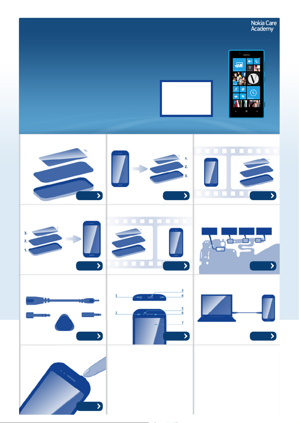
Exploded view Disassembly steps Disassembly video
Check the repair
policy before
performing any
mechanical repair
on Service Level
1&2!
Mor
Mor
Assembly steps Assembly video Solder components
Mor
Mor
Service devices Product controls and interfaces Service concept
Mor
Mor
Mor
Mor
Mor
Phone reset
Mor
©2013 Nokia | Nokia Internal Use only | All Rights Reserved.
Service Manual Level 1 and 2
Nokia Lumia 720
RM-885
Version 1.0
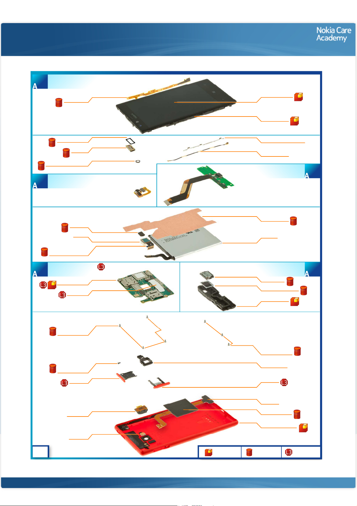
DISPLAY MODULE ASSEMBLY
(I0004 - I0006)
1
SIDEKEY FLEX
I0006
Exploded view
DISPLAY MODULE
I0005
DISPLAY FRAME
I0004
EARPIECE GASKET
EARPIECE
FRONT CAMERA GASKET
FRONT CAMERA ASSEMBLY
2
IC GASKET
CAMERA
CONNECTOR GASKET
LIGHT SWAP PACKAGE
(I0010, I0011)
4
CAMERA
LIGHT SWAP PWB
TYPE LABEL
I0008
I0007
I0009
I0014
I0015
I0016
I0010
I0011
RF COAX CABLE HOLDER
I0020
RF COAX CABLE
I0019
USB FLEX ASSEMBLY
HEATSPREADER
I0018
BATTERY
I0013
MAIN ANTENNA ASSEMBLY
(I0021 - I0023)
IHF SPEAKER
I0022
IHF SPEAKER GASKET
I0021
MAIN ANTENNA
I0023
3
5
v1.0
SCREW TORX+
SIZE 4 M1.4 x 2.5
SIZE 2 M1.2 x 2.6
I0012
SCREW TORX+
I0002
SIM DOOR
I0001
AV MODULE
I0027
FLASH LED
I0026
Only available
as assembly
©2013 Nokia | Nokia Internal Use only | All Rights Reserved.
SCREW TORX+
SIZE 4 M1.4 x 2.5
I0024
CAMERA BOOT
I0017
SD DOOR
I0003
WLC FLEX
I0029
BATTERY GASKET
I0028
UNIBODY ASSEMBLY
I0025
Not reuseable
after removal
Repair/swap
only in level 3
Service Manual Level 1 and 2
Nokia Lumia 720
RM- 885
Version 1.0
Disassembly steps
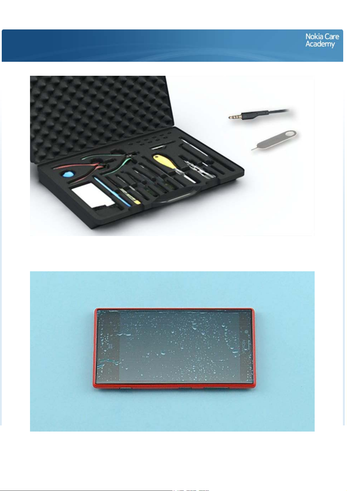
1) For disassembling you need the Nokia Standard toolkit version 2. You will also need an AV plug and the
SIM door key.
2) Protect the DISPLAY MODULE with protective film.

3) Insert the SIM door key to the small hole on the SD DOOR and press it gently. Remove the SD DOOR.
4) Insert the SIM door key to the small hole on the SIM DOOR and press it gently. Remove the SIM DOOR.
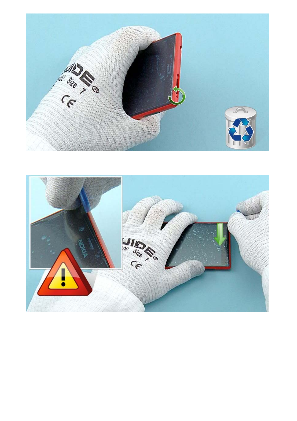
5) Unscrew the TORX+ size 2 screw. Do not use it again. Discard it.
6) To release the DISPLAY MODULE insert the SRT-6 to the top left corner of the device and slide to the
direction shown. Be careful not to damage the UNIBODY ASSEMBLY!
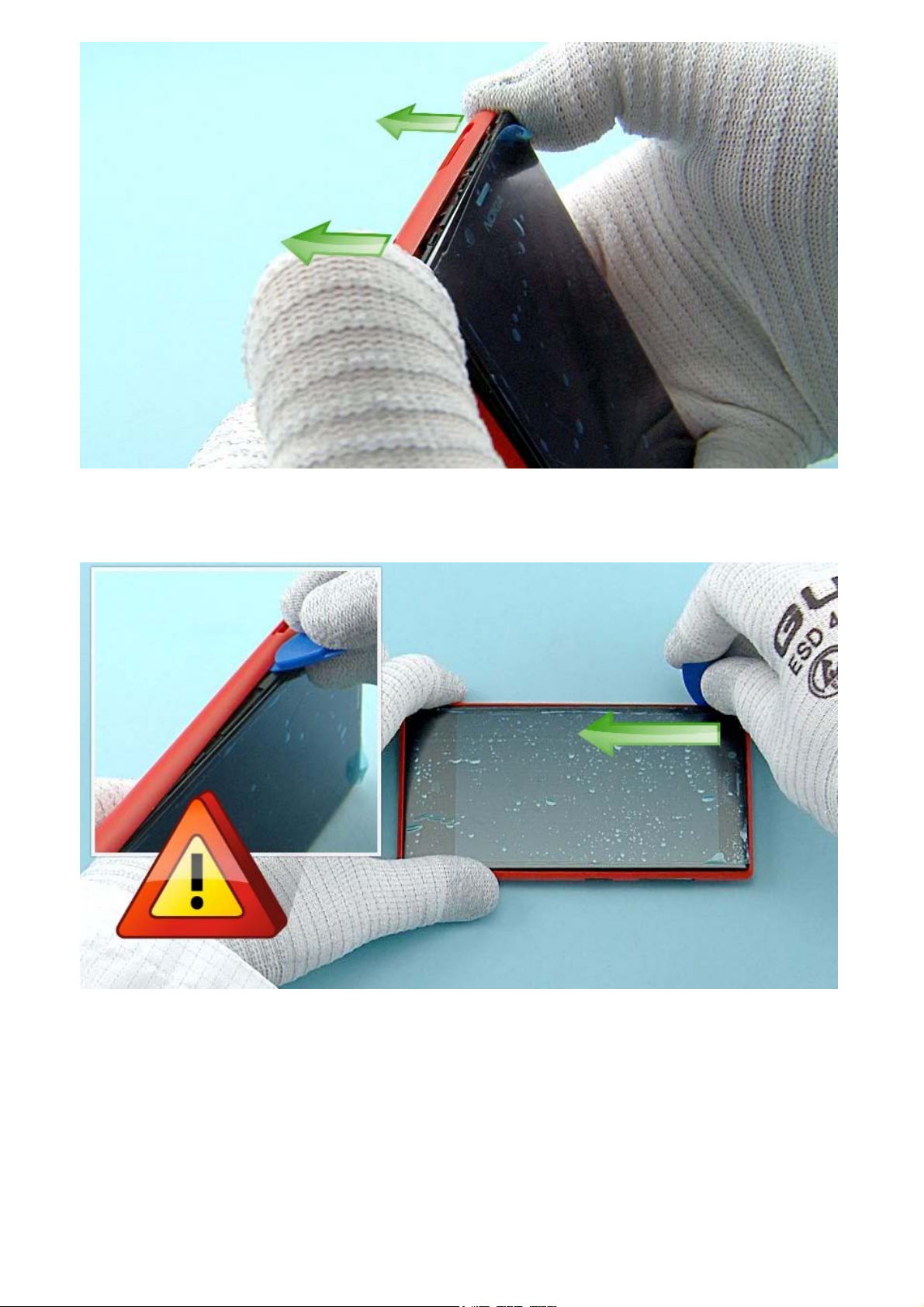
7) Push the top end of the UNIBODY ASSEMBLY to the direction shown to release the top part of the
DISPLAY MODULE.
8) Release the left side of the UNIBODY ASSEMBLY by sliding the SRT-6 to the direction shown. Be
careful not to damage the UNIBODY ASSEMBLY!

9) Release the four clips on the right side of the device with the SRT-6. Do not slide the SRT-6 as it might
damage the SIDEKEY FLEX!
10) Lift the top end of the DISPLAY MODULE up first. The DISPLAY MODULE and the UNIBODY ASSEMBLY
can now be separated.
11) Use the AV plug to lever up the AV MODULE. Remove the AV MODULE.
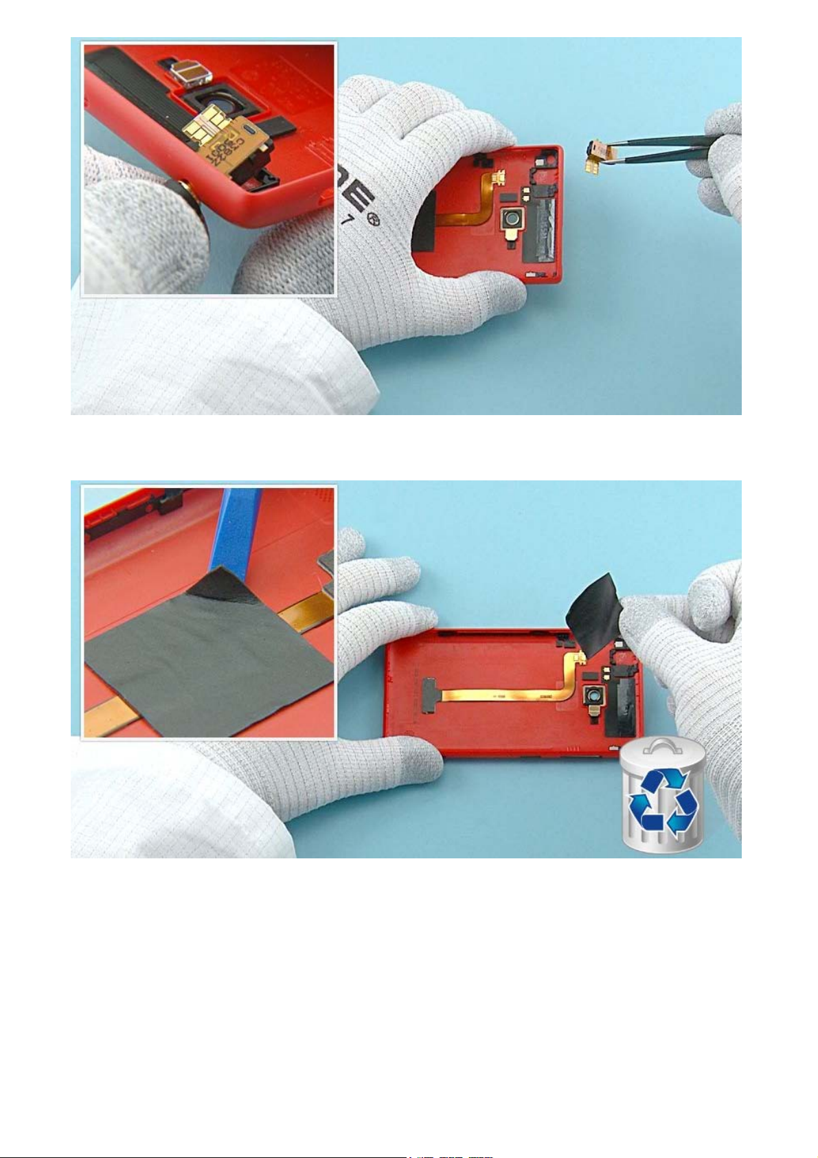
12) Lift one corner of the BATTERY GASKET with the SS-93 and peel it off. Do not use it again. Discard it.
13) Use the SS-93 to release the top end of the WLC FLEX. Be careful not to damage it!
14) Then release the middle part of the WLC FLEX. Be careful not to bend the flex!
15) Carefully release the bottom end of the WLC FLEX and remove it. Be careful not to damage the flex!
16) Use the SS-93 to release the FLASH LED. Remove it with tweezers.
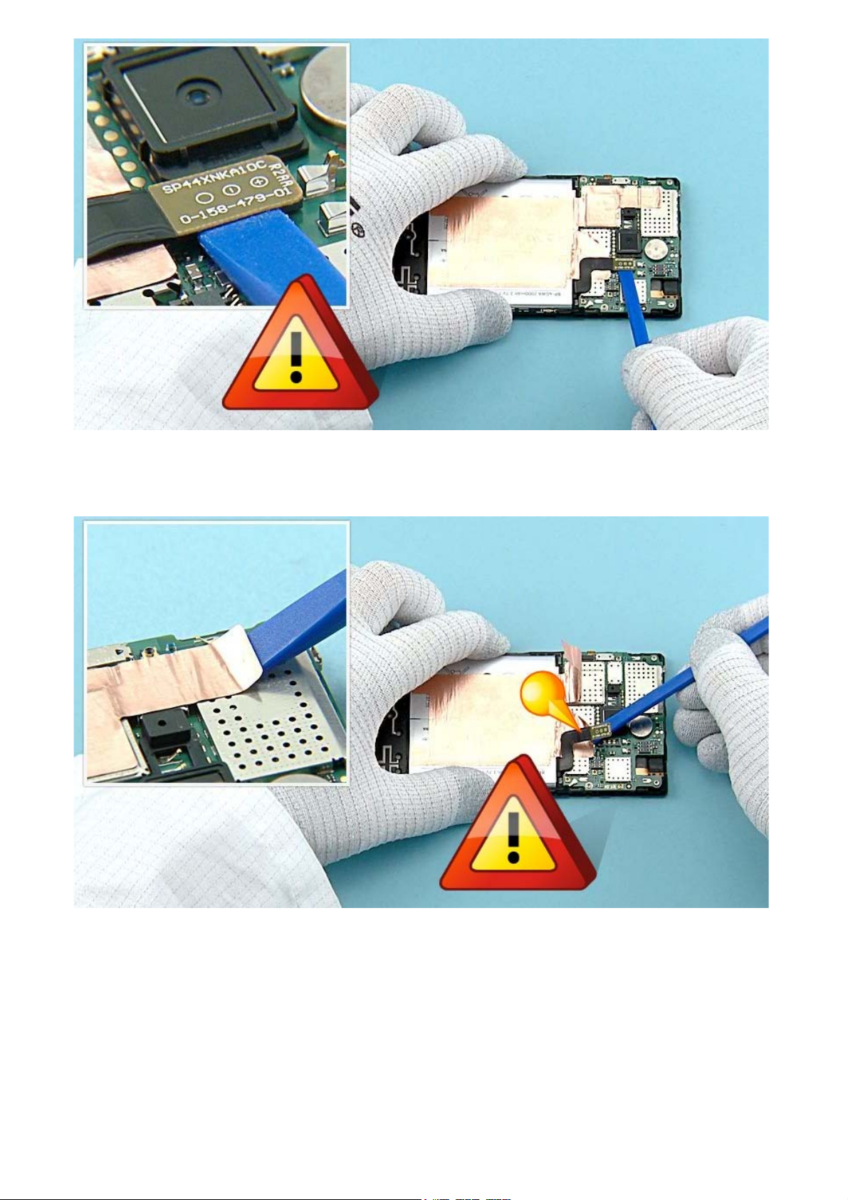
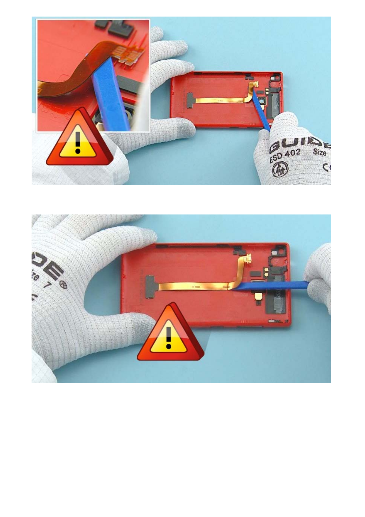
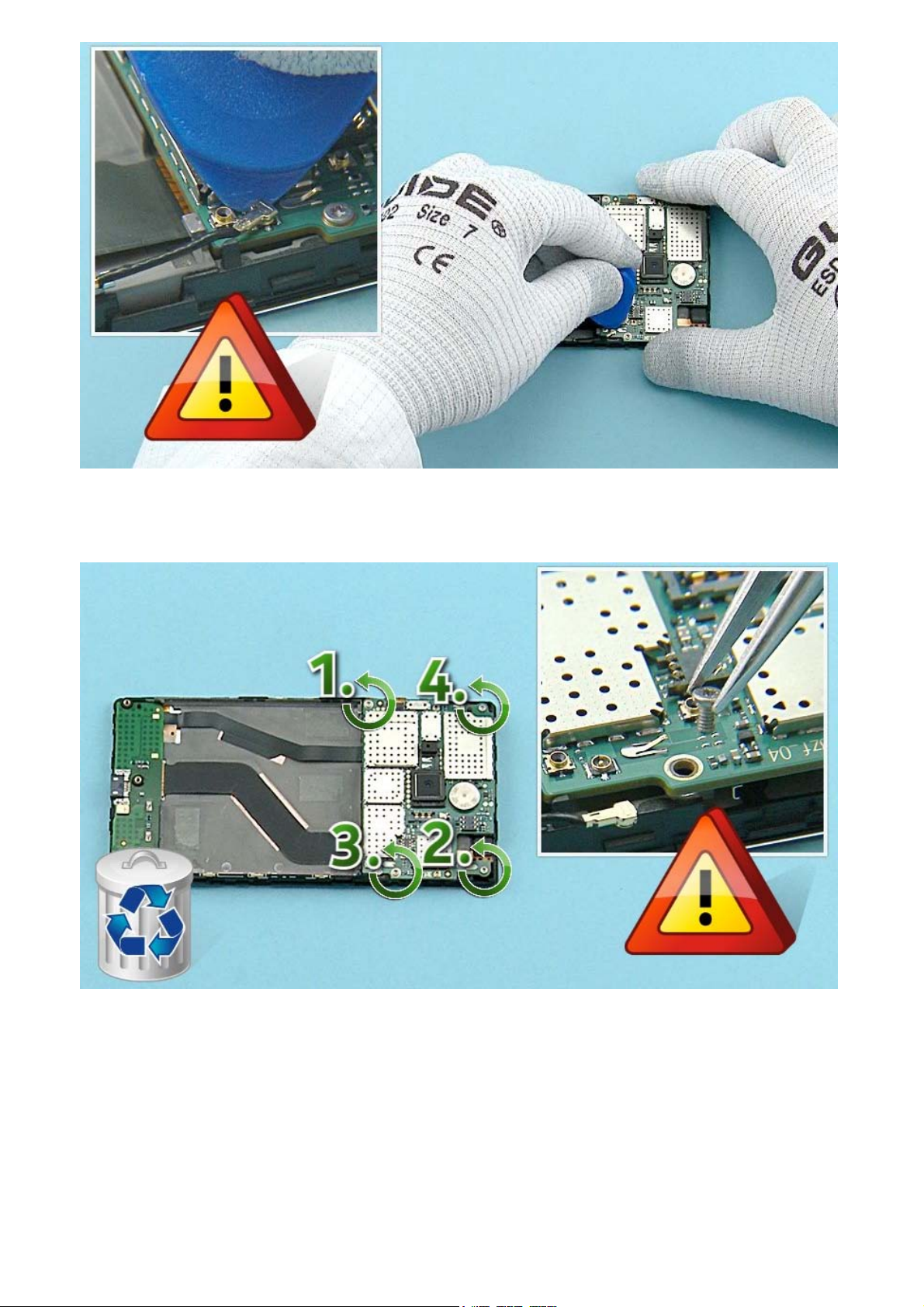
17) Open the BATTERY connector with the SS-93. Be careful not to damage the connector or any
components nearby!
18) Use the SS-93 to release the top parts of the HEATSPREADER. Be careful not to damage the
BATTERY connector!
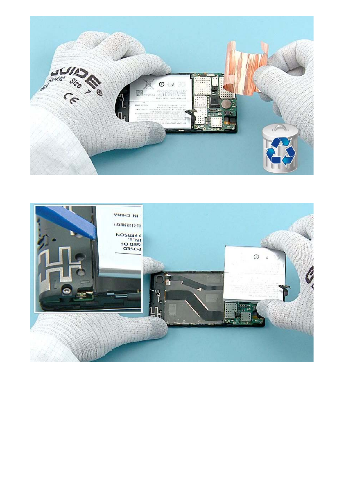
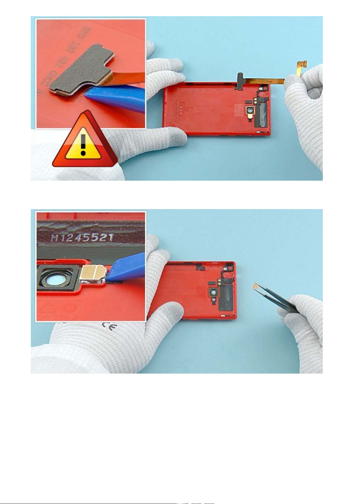
19) Peel off the HEATSPREADER completely. Do not use it again. Discard it.
20) Lift up the BATTERY with the SS-93 from the bottom end. Remove the BATTERY.
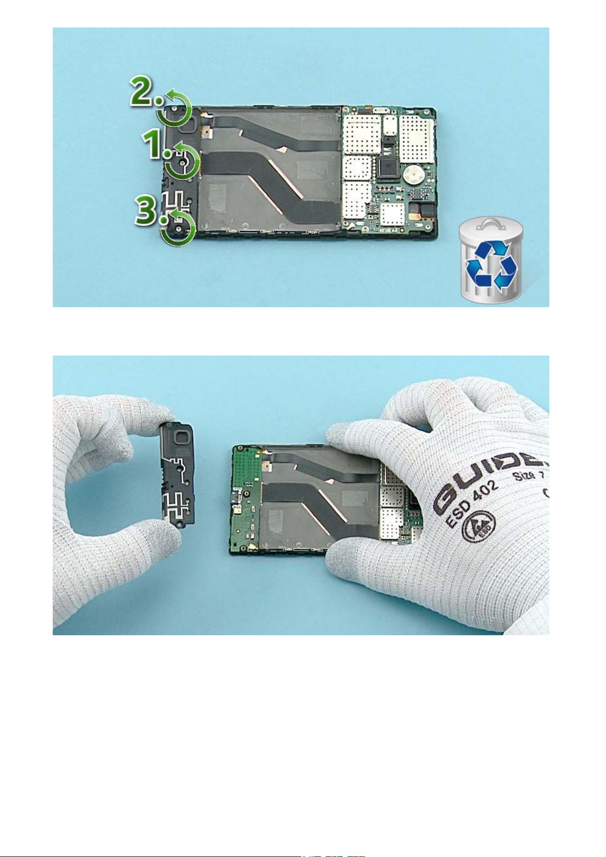
21) Unscrew the three Torx+ size 4 screws in the order shown. Do not use them again. Discard them.
22) Lift up and remove the MAIN ANTENNA.
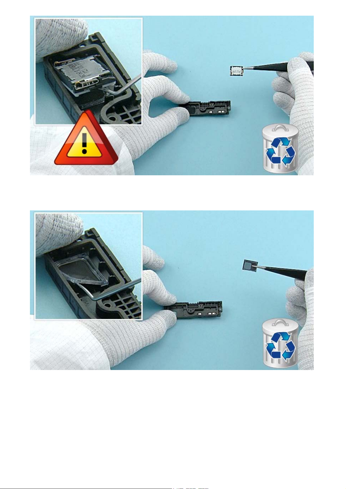
23) Use the dental tool to lever up the IHF SPEAKER. Be careful not to injure yourself with the sharp end
of the dental tool. The IHF SPEAKER is not reusable. Discard it.
24) Release also the IHF SPEAKER GASKET with the dental tool. Discard it.
25) Use the SRT-6 to release the top end of the RF COAX CABLE. Be very careful when opening the
connector! Be also careful not to damage any components nearby!
26) Unscrew the four Torx+ size 4 screws in the order shown. Remove the screws with tweezers to avoid
damaging the components on the ENGINE BOARD! Do not use these screws again. Discard them.
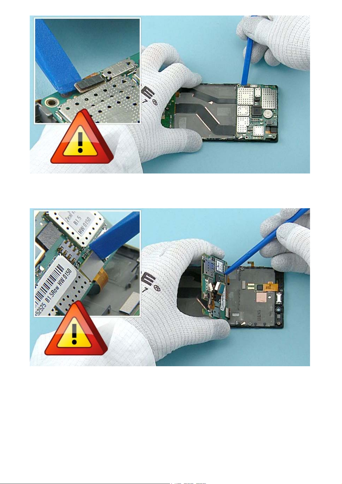
27) Use the SS-93 to open the SIDEKEY FLEX connector. Be careful not to damage the connector or any
components nearby!
28) Turn the ENGINE BOARD over as shown. Open the DISPLAY connector with the SS-93. Be careful not
to damage the connector or any components nearby!
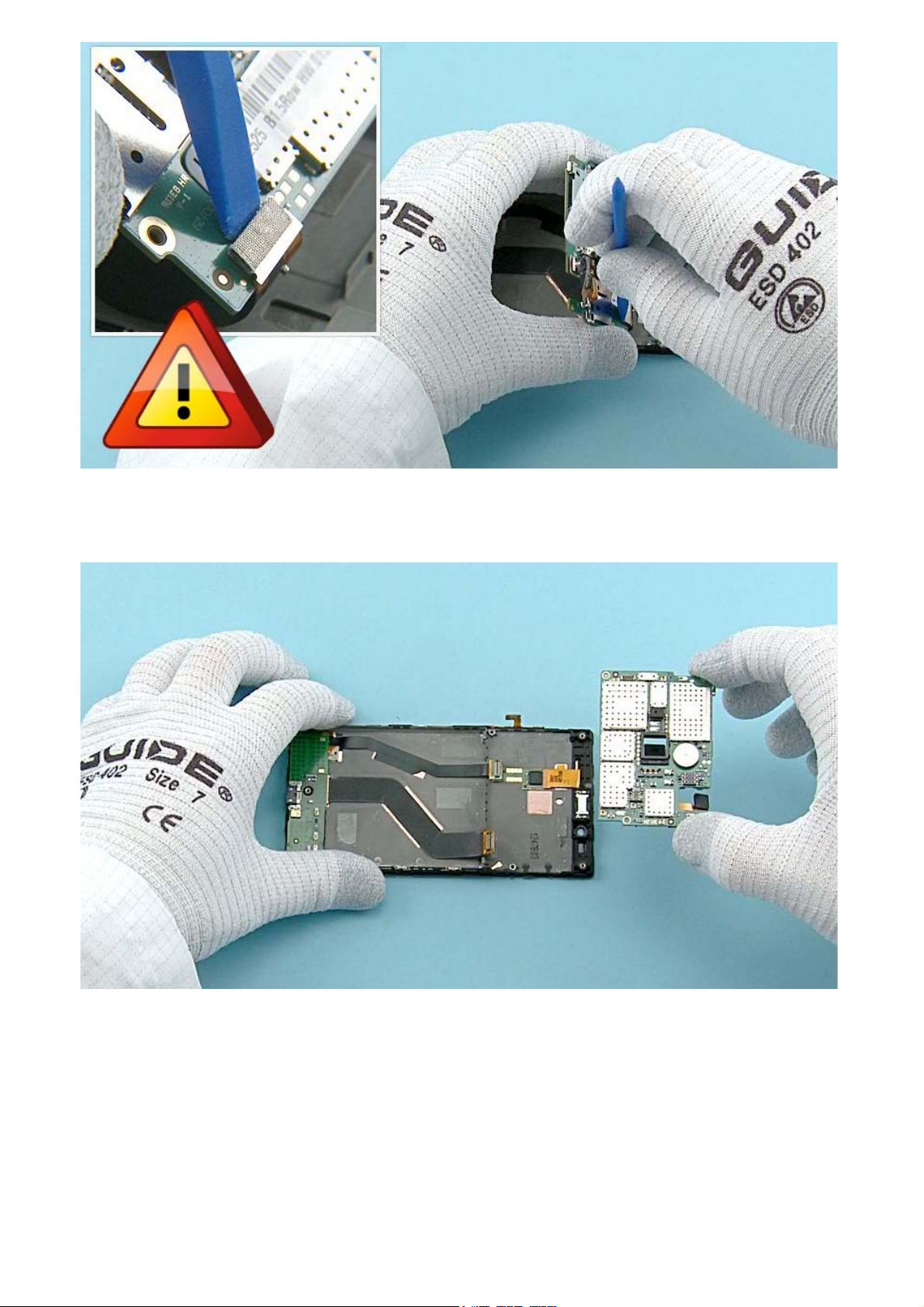
29) Open also the USB FLEX connector with the SS-93. Be careful not to damage the connector or any
components nearby!
30) The ENGINE BOARD can now be separated.
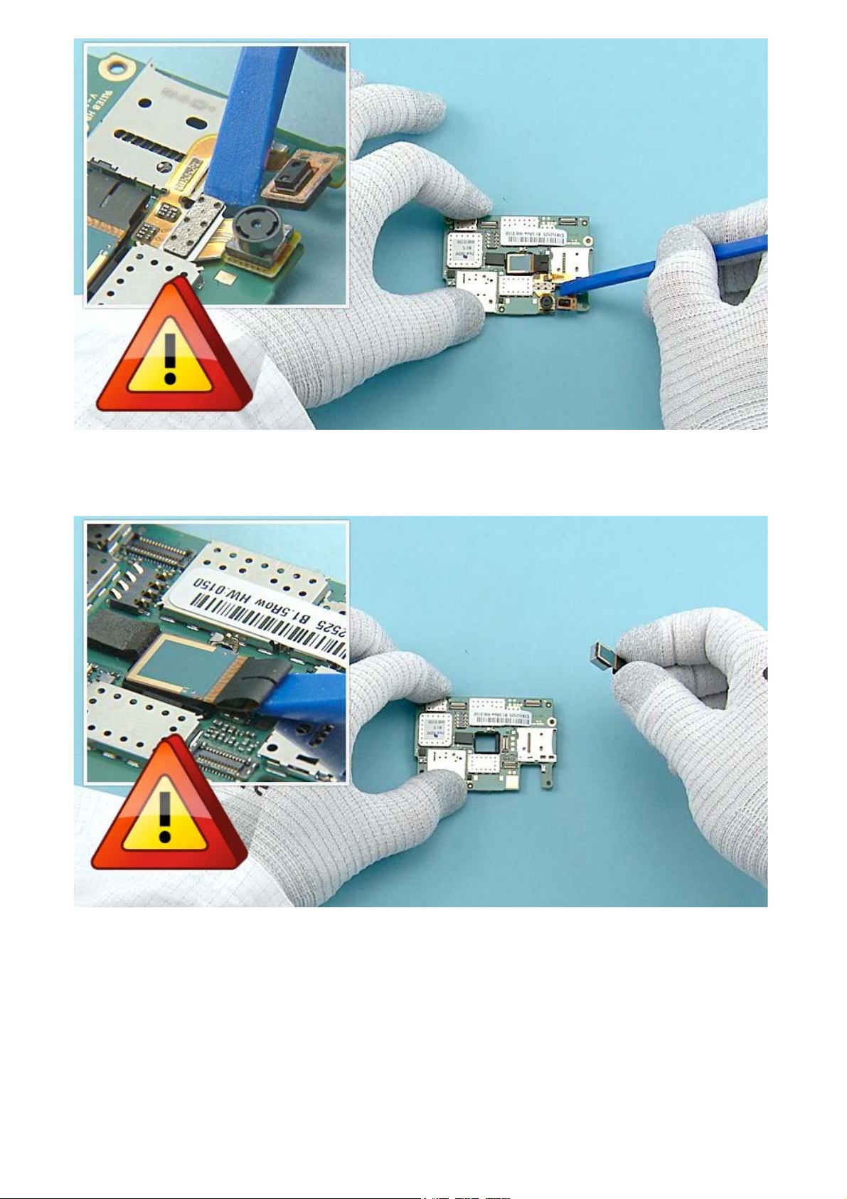
31) Open the FRONT CAMERA connector with the SS-93 and remove it. Be careful not to damage the
connector or any components nearby!
32) Open the CAMERA connector with the SS-93 and remove it. Be careful not to damage the connector
or any components nearby!
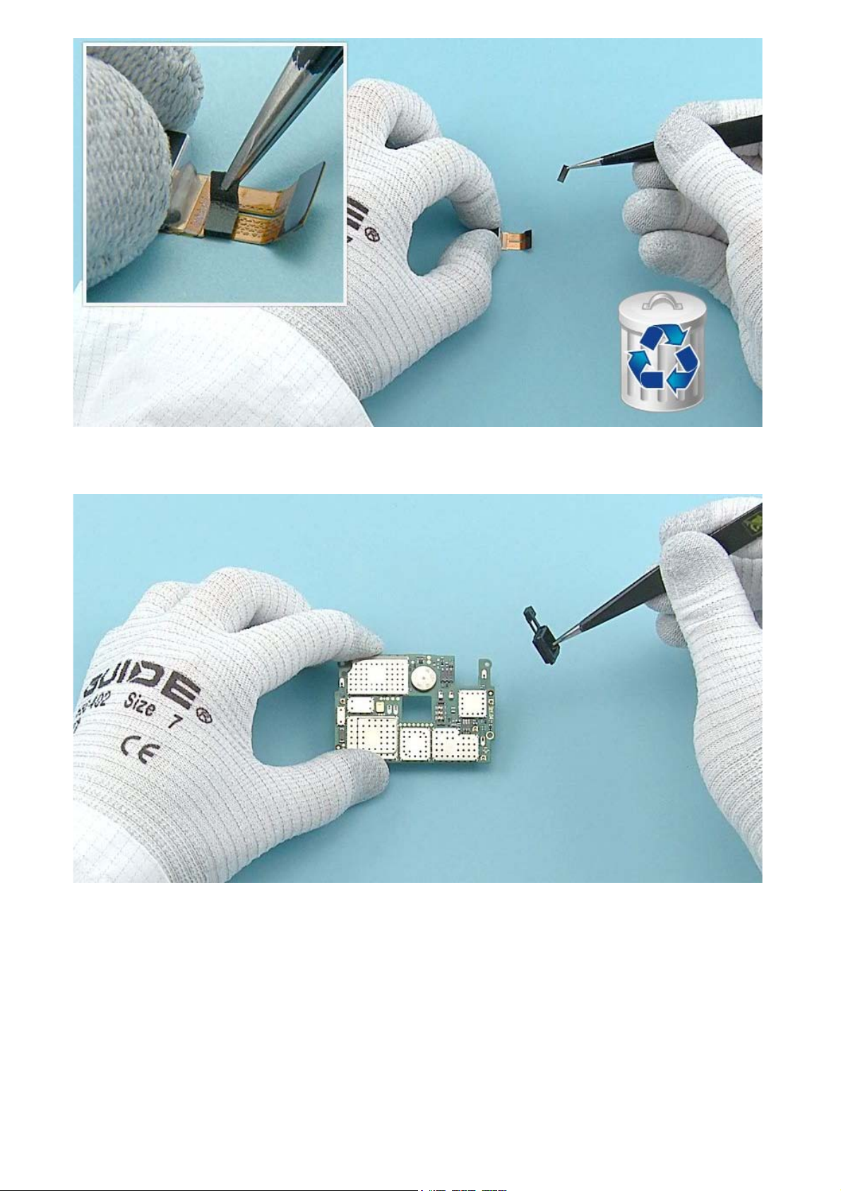
33) Remove the CAMERA CONNECTOR GASKET with tweezers. Do not use it again. Discard it.
34) Remove the CAMERA BOOT.
 Loading...