

Nokia Lumia 610, RM-835, RM836 Service Manual
Service Manual for L1 and L2
Nokia Lumia 610
RM-835 RM-836
Key features
Most affordable Nokia Lumia yet
Updated Windows Phone operating system
8 GB internal mass memory
3.7" WVGA 800 x 480 pixels LCD TFT display
Version 1.0
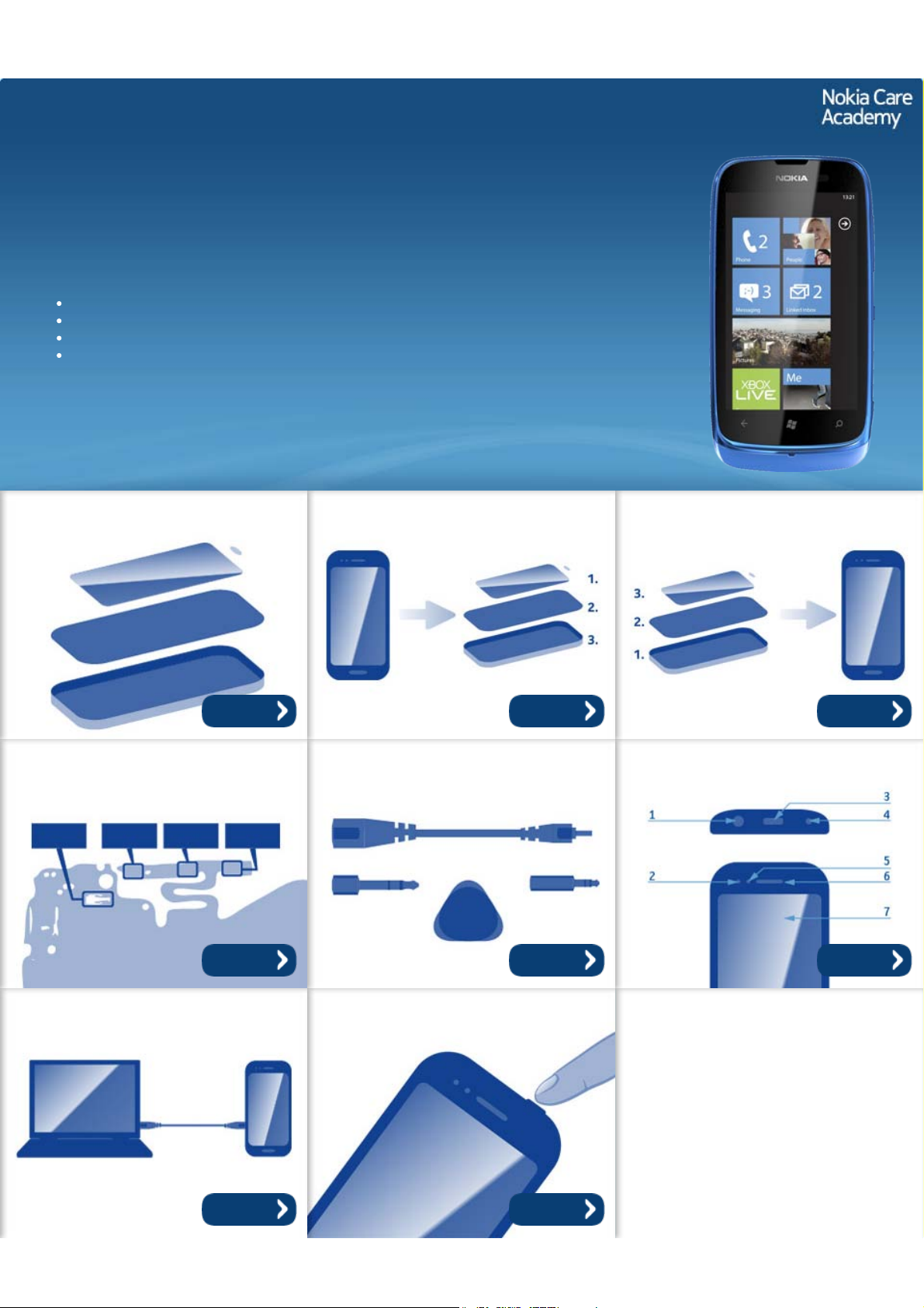
Exploded view Disassembly steps Assembly steps
More More More
Solder components Service devices Product controls and interfaces
More More More
Service concept Phone reset
More More
©2012 Nokia | Nokia Internal Use only | All Rights Reserved.
Service Manual Level 1 and 2
Nokia Lumia 610
RM-835 RM-836
Version 1.0
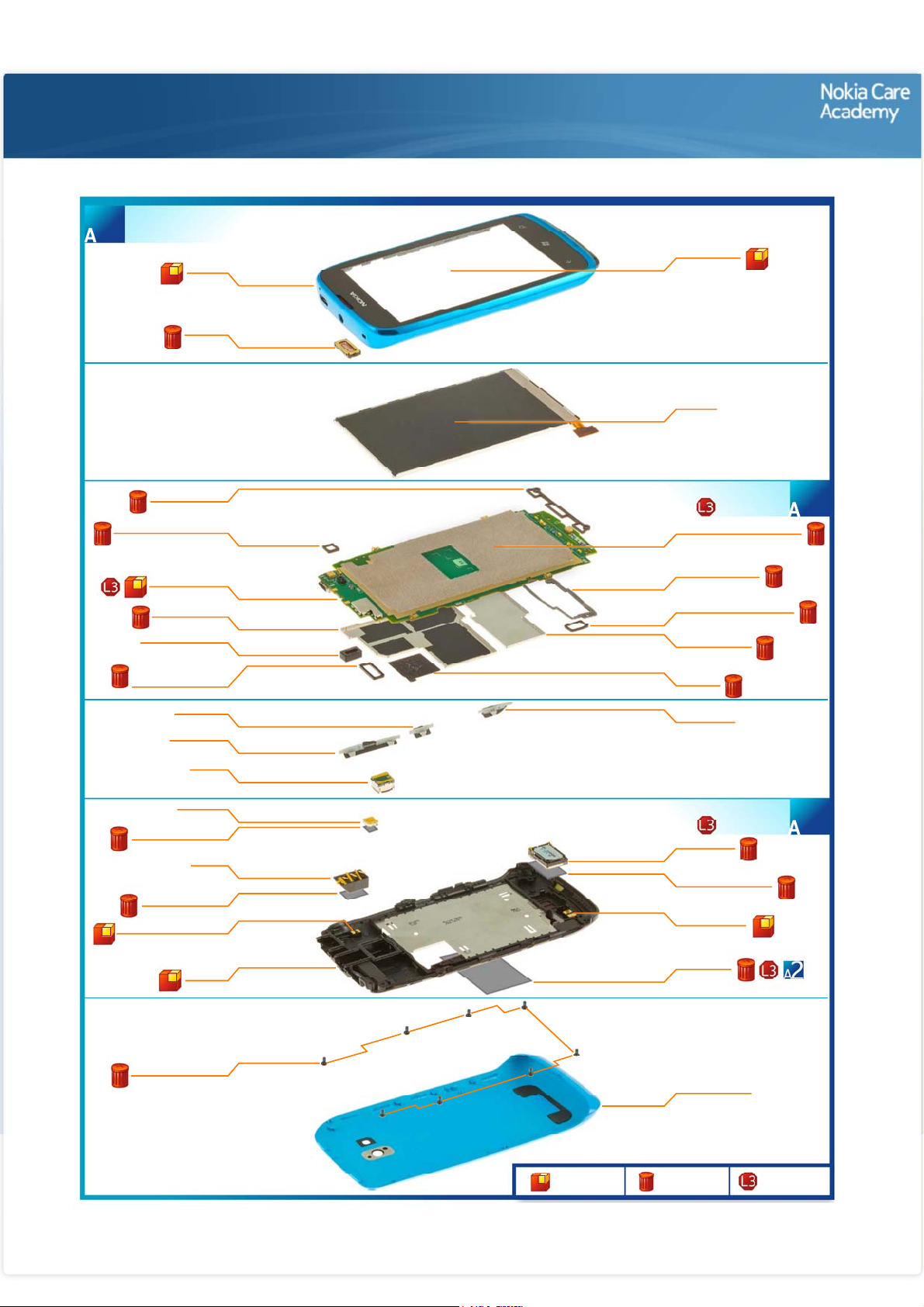
A-COVER ASSEMBLY
(I0001 - I0003)
1
A-COVER
I0002
EARPIECE
I0003
Exploded view
TOUCH PANEL
I0001
DISPLAY
I0007
KEY LED RUBBER
SECONDARY MIC RUBBER
LIGHT SWAP PWB
SHIELDING LID 2
LED FLASH RUBBER
CONNECTOR RUBBER
LED FLASH ADHESIVE
AV JACK ADHESIVE
BT/GPS/WLAN ANTENNA
I0009
I0008
I0018
I0016
I0017
TOUCH PANEL
I0012
POWER KEY
I0006
VOLUME KEY
I0004
CAMERA
I0020
LED FLASH
I0025
I0026
AV JACK
I0023
I0024
I0028
D-COVER
I0029
LIGHT SWAP PACKAGE
D-COVER ASSEMBLY
(I0008 - I0019)
DISPLAY CONDUCTIVE TAPE
I0010
ANTENNA RUBBER
I0014
LCD CONNECTOR RUBBER
I0011
SHIELDING LID 1
I0015
SIM TAPE
I0013
CAMERA KEY
I0005
(I0021 - I0029)
IHF SPEAKER
I0021
IHF SPEAKER GASKET
I0022
MAIN ANTENNA
I0027
TYPE LABEL
I0019
2
3
SCREW TORX+ SIZE 4
I0030
Only available
as assembly
©2012 Nokia | Nokia Internal Use only | All Rights Reserved.
BATTERY COVER
I0031
Not reuseable
after removal
Repair/swap
only in level 3
Service Manual Level 1 and 2
Nokia Lumia 610
RM- 835, RM -836
Version 1.0
Disassembly steps
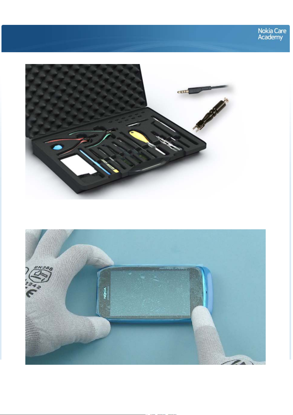
For disassembling you need the Nokia Standard toolkit version 2. You will also need the camera removal
tool SS-287 and an AV plug.
Protect the A-COVER with protective film.
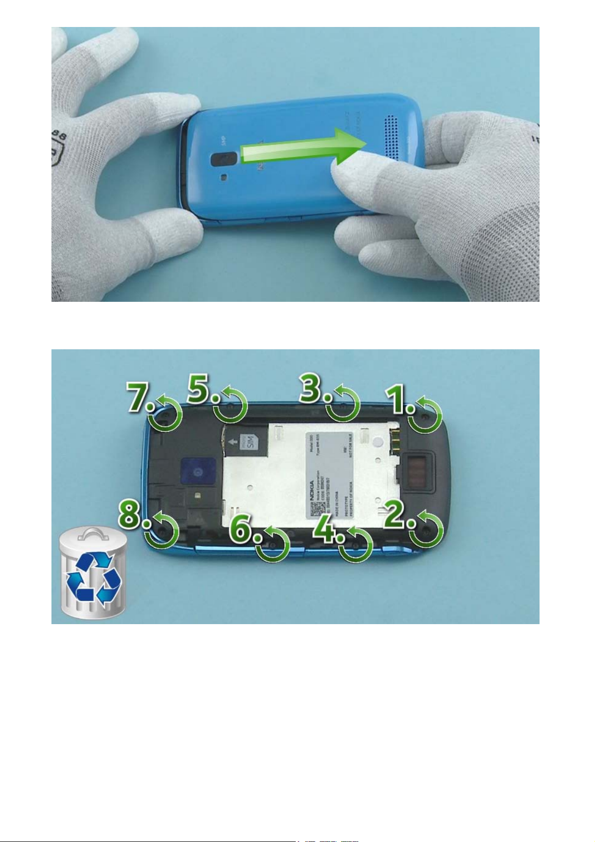
Open the BATTERY COVER by pulling it to the direction shown. Remove the BATTERY COVER.
Unscrew the eight Torx+ size 4 screws in the order shown. Do not use them again. Discard them.
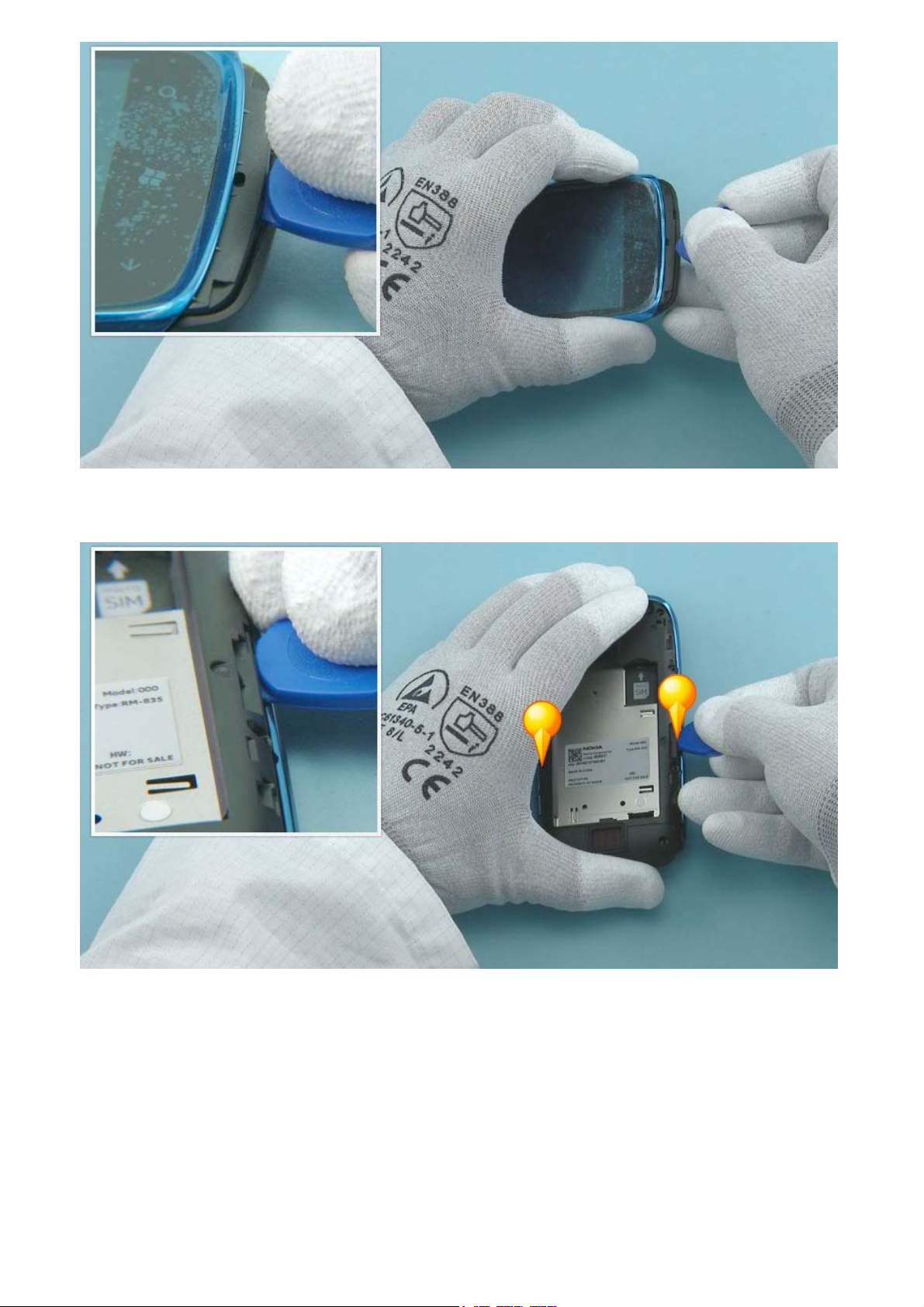
Insert the SRT-6 to the shown place and release the bottom end of the D-COVER.
Release also both sides of the D-COVER with the SRT-6.
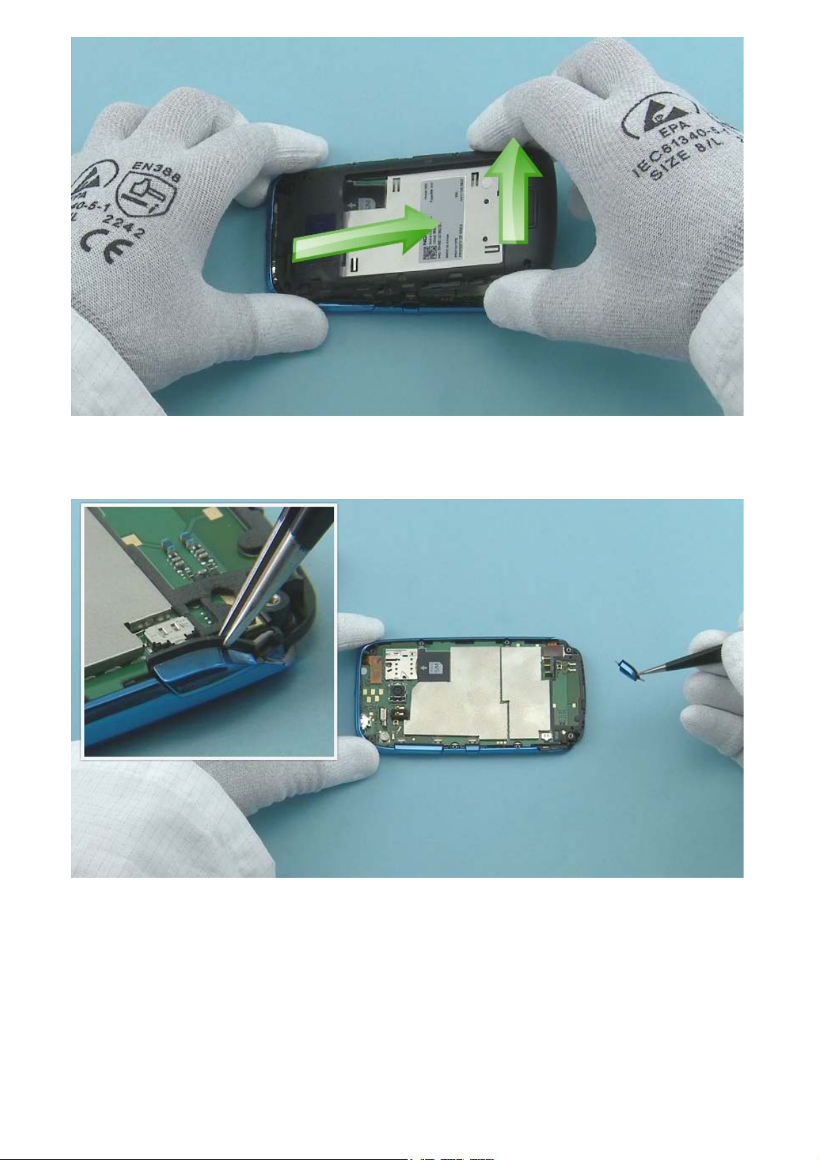
Lift up the bottom end of the D-COVER and pull it to the direction shown. The D-COVER can now be
separated.
Remove the CAMERA KEY with tweezers.
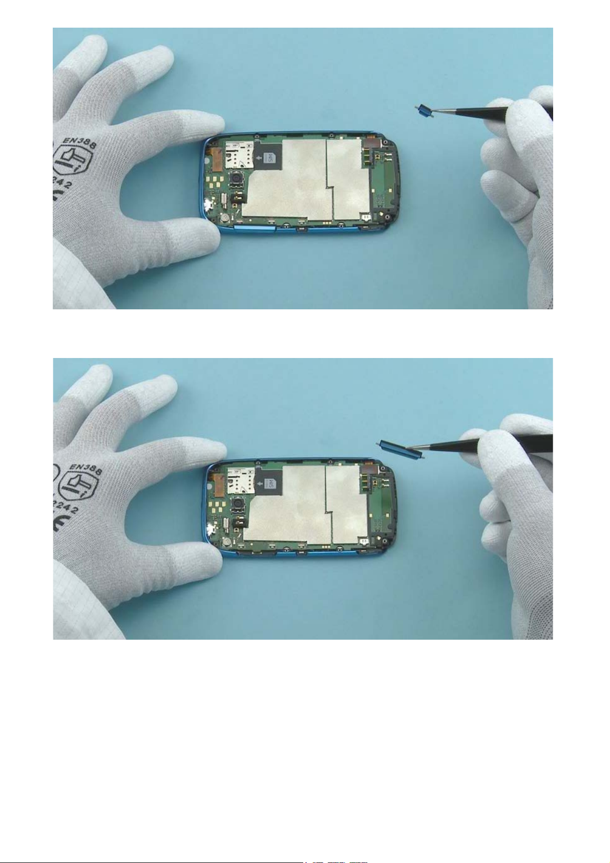
Remove the POWER KEY with tweezers.
Remove the VOLUME KEY with tweezers.
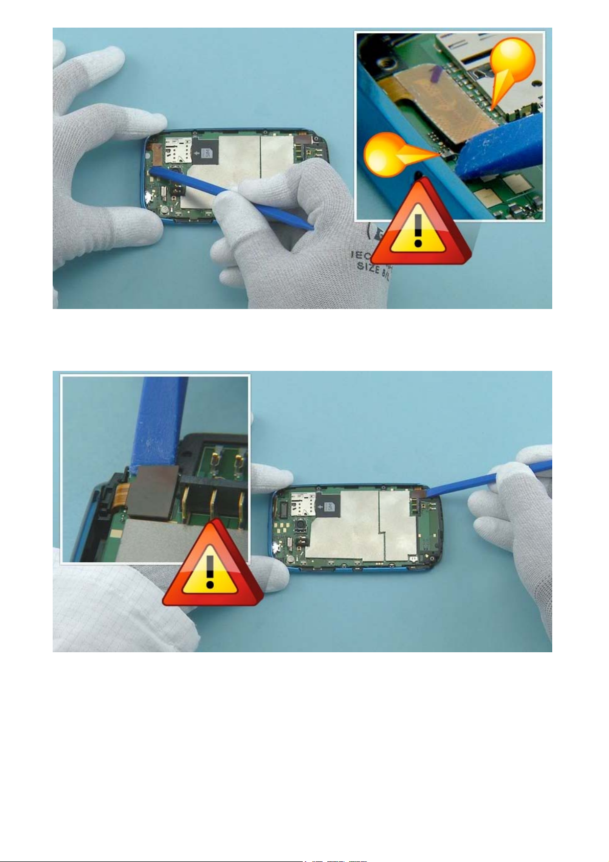
Use the SS-93 to open the TOUCH PANEL connector. Be very careful not to damage the connector or
the small components around the connector.
Open the DISPLAY connector with the SS-93. Be careful not to damage the connector or components
nearby.
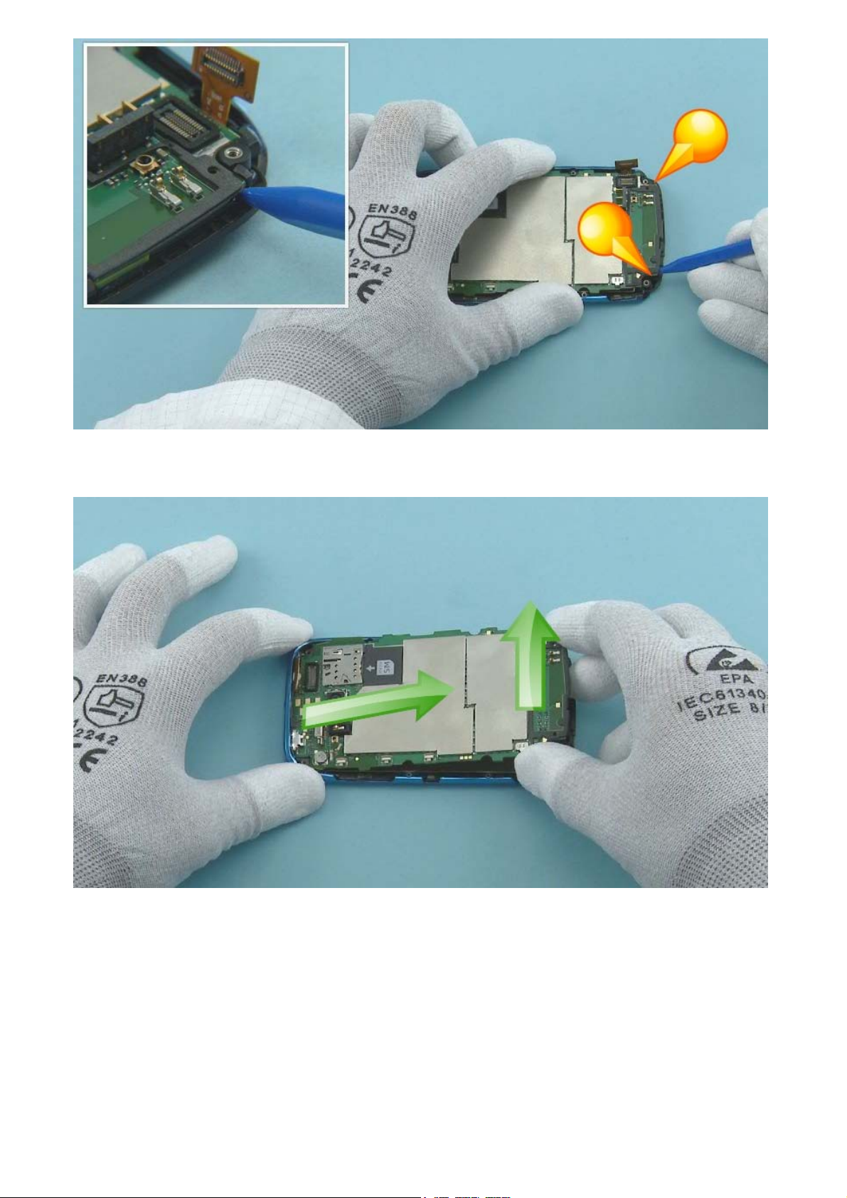
Open the two shown clips holding the ENGINE BOARD with the sharp end of the SS-93.
Lift up the bottom end of the ENGINE BOARD and pull it to the direction shown. The ENGINE BOARD can
now be separated.
 Loading...