

Page 1

Electronic user's guide released subject to "Nokia User's Guides Terms and Conditions, 7th June, 1998"
List of AT Commands for Nokia 22
Nokia 22
List of AT Commands
9356900 issue 1
Copyright © Nokia Mobile Phones 2001. All rights reserved.
Page 2

List of AT Commands for Nokia 22
2
Copyright © Nokia Mobile Phones 2001. All rights reserved.
Reproduction, transfer, distribution or storage of part or all of the contents in this document in any
form without the prior written permission of Nokia is prohibited.
Nokia and Nokia Connecting People are registered trademarks of Nokia Corporation. Other
product and company names mentioned herein may be trademarks or tradenames of their
respective owners.
Nokia operates a policy of continuous development. Nokia reserves the right to make changes and
improvements to any of the products described in this document without prior notice.
Under no circumstances shall Nokia be responsible for any loss of data or income or any special,
incidental, consequential or indirect damages howsoever caused.
The contents of this document are provided "as is". Except as required by applicable law, no
warranties of any kind, either express or implied, including, but not limited to, the implied
warranties of merchantability and fitness for a particular purpose, are made in relation to the
accuracy, reliability or contents of this document. Nokia reserves the right to revise this document
or withdraw it at any time without prior notice.
Copyright © Nokia Mobile Phones 2001. All rights reserved.
Page 3

3
List of AT Commands for Nokia 22
TABLE OF CONTENTS
Click on the page number to go to the page.
Table of Contents................................................................................................................................ 3
1 Introduction .................................................................................................................................8
2 Data connections......................................................................................................................... 9
3 AT command syntax.................................................................................................................. 10
3.1 Register commands............................................................................................................10
3.1.1 Basic commands.............................................................................................................10
3.1.2 Extended commands....................................................................................................... 10
4 TE-TA interface commands.......................................................................................................12
4.1 V.25ter................................................................................................................................ 12
4.1.1 S3 Command line termination character.......................................................................... 12
4.1.2 S4 Response formatting character................................................................................... 12
4.1.3 S5 Command line editing character................................................................................. 12
4.1.4 E Command echo............................................................................................................ 13
4.1.5 Q Result code suppression.............................................................................................. 13
4.1.6 V DCE response format................................................................................................... 13
4.1.7 X Result code selection and call progress monitoring control.......................................... 13
4.1.8 &C Circuit 109 (received line signal detector) behaviour.................................................. 14
4.1.9 &D Circuit 108 (data terminal ready) behaviour ............................................................... 14
4.1.10 +IPR Fixed DTE rate.................................................................................................... 14
4.1.11 +ICF DTE-DCE ch a ra cter framin g................................................................................ 15
4.1.12 +IFC DTE-DCE local flow control................................................................................. 15
4.1.13 +ILRR DTE-DCE local rate reporting............................................................................ 16
4.1.14 +ES Error control selection .......................................................................................... 16
4.1.15 +EB Break handling in error control operation.............................................................. 16
4.1.16 +EFCS 32-bit frame check sequence........................................................................... 16
4.1.17 +ER Error control reporting.......................................................................................... 17
4.1.18 +ETBM Call termination buffer manage ....................................................................... 17
4.2 De facto.............................................................................................................................. 17
4.2.1 S25 Detect DTR change time.......................................................................................... 17
4.2.2 &S DSR signal behaviour................................................................................................ 17
4.2.3 &K Select flow control...................................................................................................... 17
5 Generic commands................................................................................................................... 18
5.1 V.25ter................................................................................................................................ 18
5.1.1 Z Reset to default configuration....................................................................................... 18
5.1.2 &F Set to factory-defined con figuration............................................................................ 18
5.1.3 I Request identification information.................................................................................. 18
5.1.4 +GMI Request TA manufacturer identification................................................................. 18
5.1.5 +GMM Request TA model identification........................................................................... 18
5.1.6 +GMR Request TA revision identification ........................................................................ 19
5.1.7 +GSN Request TA serial number identification................................................................ 19
5.1.8 +GCAP Request complete capabilities list....................................................................... 19
5.2 De facto.............................................................................................................................. 19
5.2.1 &V View configuration......................................................................................................19
5.2.1.1 &W Store configuration............................................................................................. 19
5.2.1.2 &Y Select power-up configuration............................................................................. 19
5.3 GSM 07.07.......................................................................................................................... 20
5.3.1 +CGMI Request ME manufacturer identification.............................................................. 20
Copyright © Nokia Mobile Phones 2001. All rights reserved.
Page 4

4
List of AT Commands for Nokia 22
5.3.2 +CGMM Request ME model identification....................................................................... 20
5.3.3 +CGMR Request ME revision identification..................................................................... 20
5.3.4 +CGSN Request ME serial number identification ............................................................ 20
5.3.5 +CSCS Sel e ct TE character se t....................................................................................... 20
5.3.6 +WS46 Select wireless network....................................................................................... 21
6 Call control commands.............................................................................................................. 22
6.1 V.25ter................................................................................................................................ 22
6.1.1 D Dial .............................................................................................................................. 22
6.1.2 T Select tone dialling....................................................................................................... 23
6.1.3 P Select pulse dialling...................................................................................................... 23
6.1.4 A Answer response ......................................................................................................... 24
6.1.5 H Hook control................................................................................................................. 24
6.1.6 O Return to online data state........................................................................................... 25
6.1.7 S0 Automatic answer....................................................................................................... 25
6.1.8 S6 Pause before blind dialling ......................................................................................... 25
6.1.9 S7 Connection completion time-out................................................................................. 25
6.1.10 S8 Comma dial modifier time....................................................................................... 26
6.1.11 S10 Automatic disconnect delay .................................................................................. 26
6.1.12 L Monitor speaker loudness......................................................................................... 26
6.1.13 M Monitor speaker mode ............................................................................................. 26
6.1.14 +DS Data compression................................................................................................ 26
6.1.15 +DR Data compression reporting................................................................................. 27
6.2 De facto.............................................................................................................................. 27
6.2.1 B CCITT/Bell mode..........................................................................................................27
6.2.2 S1 Ring count.................................................................................................................. 28
6.2.3 S2 Escape code character............................................................................................... 28
6.2.4 S12 Escape guard time................................................................................................... 28
6.2.5 +++ Escape..................................................................................................................... 28
6.3 GSM 07.07.......................................................................................................................... 28
6.3.1 +CSTA Select type of address......................................................................................... 28
6.3.2 +CMOD Call mode.......................................................................................................... 29
6.3.3 +CHUP Hang-up call....................................................................................................... 29
6.3.4 Mute control +CMUT ....................................................................................................... 30
6.3.5 Loudspeaker volume level +CLVL................................................................................... 30
6.3.6 +CBST Select bearer service type................................................................................... 30
6.3.7 +CRLP Radio link protocol............................................................................................... 32
6.3.8 +CR Service reporting control.......................................................................................... 32
6.3.9 +CEER Extended error report.......................................................................................... 33
6.3.10 +CRC Cellular result codes.......................................................................................... 33
6.3.11 +CHSR Current call parameters reporting.................................................................... 34
6.3.12 +CSNS Single numbering scheme............................................................................... 34
6.3.13 +CHSD HSCSD device parameters............................................................................. 35
6.3.14 +CHSN Parameter command syntax........................................................................... 35
6.3.15 +CHSC Current call parameters................................................................................... 36
6.3.16 +CVHU Voice Hang Up Control ................................................................................... 37
7 Network service commands (GSM 07.07) ................................................................................. 38
7.1 +CNUM Subscriber number................................................................................................ 38
7.2 +CREG Network registration............................................................................................... 38
7.3 +COPS Opera tor selection.................................................................................................. 39
7.4 +CLCK Facility lock............................................................................................................. 40
Copyright © Nokia Mobile Phones 2001. All rights reserved.
Page 5

5
List of AT Commands for Nokia 22
7.5 +CPWD Change password ................................................................................................. 42
7.6 +CLIP Calling line identification presentation ...................................................................... 42
7.7 +CLIR Calling line identification restriction.......................................................................... 43
7.8 +COLP Connected line identification presentation .............................................................. 44
7.9 +CCWA Call waiting............................................................................................................ 45
7.10 +CUSD Unstructured supplementary service data.............................................................. 46
7.11 +CSSN Supplementary service notifications....................................................................... 47
7.12 +CLCC List current calls ..................................................................................................... 47
7.13 +CCUG Closed user group................................................................................................. 48
7.14 +CCFC Call Forwarding Number and Conditions................................................................ 49
7.15 +CHLD Call related to SSs.................................................................................................. 50
7.16 +CAOC Advice of charge.................................................................................................... 50
8 ME control and status commands (GSM 07.07)........................................................................ 51
8.1 +CPWC ME power class control......................................................................................... 51
8.2 +CPAS Phone activity status............................................................................................... 52
8.3 +CFUN Set phone functionality........................................................................................... 52
8.4 +CPIN Enter PIN................................................................................................................. 52
8.5 +CSQ Signal quality............................................................................................................ 53
8.6 +CPBS Select phonebook memory storage........................................................................ 54
8.7 +CPBF Find phonebook entries.......................................................................................... 55
8.8 +CPBW Write phonebook entry .......................................................................................... 56
8.9 +CIND Indicator control....................................................................................................... 57
8.10 +CMER ME event reporting ................................................................................................ 57
9 ME error command (GSM 07.07)............................................................................................... 58
9.1 +CMEE Report mobile equipment error .............................................................................. 58
10 SMS commands (GSM 07.05)................................................................................................... 59
10.1 +CSMS Select message service......................................................................................... 59
10.2 +CPMS Preferred message storage.................................................................................... 59
10.3 +CMGF Message format ..................................................................................................... 60
10.4 +CSCA Service centre address........................................................................................... 60
10.5 +CSMP Set text mode parameters...................................................................................... 61
10.6 +CSDH Show text mode parameters .................................................................................. 61
10.7 +CSCB Select cell broadcast message types ..................................................................... 62
10.8 +CSAS Save settings.......................................................................................................... 62
10.9 +CRES Restore settings..................................................................................................... 63
10.10 +CNMI New message indications to TE.............................................................................. 63
10.11 +CMGL List messages........................................................................................................65
10.12 +CMGR Read message...................................................................................................... 67
10.13 +CNMA New message acknowledgement to ME/TA........................................................... 69
10.14 +CMGS Send message...................................................................................................... 70
10.15 +CMSS Send message from storage.................................................................................. 71
10.16 +CMMS More messages to send........................................................................................ 72
10.17 +CMGW Write message to memory.................................................................................... 73
10.18 +CMGD Delete message.................................................................................................... 74
10.19 +CMGC Send command..................................................................................................... 74
11 Voice commands ....................................................................................................................... 76
11.1 +VTS DTMF generation...................................................................................................... 76
12 Miscellaneous commands......................................................................................................... 77
12.1 V.25ter................................................................................................................................ 77
12.1.1 A/ Repeat last command line ....................................................................................... 77
Copyright © Nokia Mobile Phones 2001. All rights reserved.
Page 6

6
List of AT Commands for Nokia 22
12.1.2 S47 Force fax class 2/2.0 error correction mode.......................................................... 77
13 Fax commands .......................................................................................................................... 78
13.1 TIA-578-A ........................................................................................................................... 78
13.2 TIA-592............................................................................................................................... 78
13.3 TIA SP-2388....................................................................................................................... 79
14 Result codes.............................................................................................................................. 81
14.1 V.25ter................................................................................................................................ 81
14.1.1 Basic syntax result codes............................................................................................. 81
14.1.2 +DR Data compression report...................................................................................... 81
14.1.3 +ILRR DTE-DCE local rate report................................................................................ 81
14.2 De fac to.............................................................................................................................. 82
14.2.1 Call repeat restriction result codes............................................................................... 82
14.3 GSM 07.07.......................................................................................................................... 82
14.3.1 +CSSI Intermediate supplementary service notification................................................ 82
14.3.2 +COLP Connected line identification report.................................................................. 82
14.3.3 +CR Data service report............................................................................................... 83
14.3.4 +CRING Distinctive ring............................................................................................... 83
14.3.5 +CLIP Calling line identification report.......................................................................... 83
14.3.6 +CSSU Unsolicited supplementary service notification ................................................ 84
14.3.7 +CCWA Call waiting..................................................................................................... 84
14.3.8 +CREG Network registration........................................................................................ 86
14.3.9 +CUSD Network initiated unstructured supplementary service data............................. 86
14.3.10 +CME ERROR Mobile equipment error........................................................................ 87
14.4 GSM 07.05.......................................................................................................................... 87
14.4.1 +CMTI New SMS-DELIVER indication......................................................................... 87
14.4.2 +CMT New SMS-DELIVER.......................................................................................... 88
14.4.3 +CBM New CBM.......................................................................................................... 89
14.4.4 +CDSI New SMS-STATUS-REPORT indication........................................................... 90
14.4.5 +CDS New SMS-STATUS-REPORT........................................................................... 90
14.4.6 +CMS ERROR Message service failure....................................................................... 91
15 Error values............................................................................................................................... 92
15.1 +CME ERROR values......................................................................................................... 92
15.2 +CMS ERROR values......................................................................................................... 93
16 References................................................................................................................................ 95
17 Example procedures on some at-commands............................................................................. 96
17.1 Inputting PIN CODE............................................................................................................ 96
17.2 Initialising the Nokia 22....................................................................................................... 96
17.3 Sending an SMS from a terminal or other similar application .............................................. 97
17.4 Sending a sample SMS in the text mode............................................................................. 97
17.5 HSCSD command examples............................................................................................... 98
Copyright © Nokia Mobile Phones 2001. All rights reserved.
Page 7

List of AT Commands for Nokia 22
Abbreviations
AT Attention
BCD Binary Coded Decimal
CBM Cell Broadcast Message
CIS PCMCIA Card Information Structure
CLI Calling Line Identity
COL Connected Line identit y
COR Configuration Option Register
CR Carriage Return
CTS Clear To Send
DCD Data Carrier Detect
DCE Data Circuit-terminating Equipment; see TA
DTE Data Terminal Equipment; see TE
DTMF Dual Tone Multiple Frequency
DTR Data Terminal Ready
DSR Data Set Ready
EMC Electro-Magnetic Compatibility
ERL Echo Return Loss
ESD Electro-Static Discharge
GSM Groupe Special Mobile, Global System for Mobile communications
HSCSD High Speed Circuit Switched Data
IMEI International Mobile station Equipment Identity
IRA International Reference Alphabet
ISDN Integrated Services Digital Network
ITU International Telecommunication Union
IWF Interworking Function
ME Mobile Equipment, e.g. a GSM phone
MO Mobile Originated
MT Mobile Terminated
MS Mobile Station
MSISDN Mobile Station ISDN Number
PC Personal Computer
PCM Pulse Code Modulation
PDU Protocol Data Unit
PIN Personal Identity Number
PUK Personal Unblocking Key
RI Ring Indicator
RLP Radio Link Protocol
RTS Request To Send
SIM Subscriber Identity Module
SM Short Mes s ag e
SMS Short Mes s ag e Ser vic e
SMSC Short Message Service Centre
TA Terminal Adapter, the physical equipment where AT command interpreter resides
(May be combined with ME)
TE Terminal Equipment, the physical equipment from where applications communicate
with TA using AT commands
TIA Telecommunications Industry Association
UART Universal Asynchronous Receiver Transmitter
USRT Universal Synchronous Receiver Transmitter
USSD Unstructured Supplementary Service Data
7
Copyright © Nokia Mobile Phones 2001. All rights reserved.
Page 8

8
List of AT Commands for Nokia 22
1 INTRODUCTION
This document describes the AT commands that can be used to operate the Nokia 22 PBX
connectivity terminal. Other specifications on the terminal can be found in the Nokia 22 User's
Guide and Nokia 22 Operator's Guide.
All the mandatory and optional ITU-T V.25ter /1/, ETS GSM 07.07 /2/, and ETS GSM 07.05 /3/
commands that are applicable to the Nokia 22 are included in the Nokia 22 command set. The 'de
facto' commands that are widely used with modems are also supported. Note that the ITU-T
V.25ter is a combination of three TIA standards (TIA-602, TIA-615, IS-131).
The Nokia 22 can be used as an adapter for a Group 3 facsimile terminal that supports facsimile
Service Classes 1, 2 and 2.0. The supported facsimile AT commands are listed according to the
standards in which they are specified: Service Class 1 TIA-578-A /4/, Service Class 2.0 TIA-592 /5/
and Service Class 2 TIA SP-2388 /6/. TIA SP-2388 is a draft of a coming standard, but here it is
referred to as a public standard.
The Nokia 22 can be operated using a compatible computer or other devices with a 9-pin RS232
connector.
Copyright © Nokia Mobile Phones 2001. All rights reserved.
Page 9
9
List of AT Commands for Nokia 22
2 DATA CONNECTIONS
The Nokia 22 supports non-transparent and transparent data connections and High Speed Circuit
Switched Data (HSCSD) in non-transparent mode, which enables a higher data transfer rate. Time
slot usage is presented as the number of up and down links. The Nokia 22 data transfer modes are
presented in Table 1.
Table 1. The Nokia 22 data transfer modes.
Data transfer mode Mode Data rate
Non-transparent data Asynchronous data 9600 kbps
Asynchronous data 14400 kbps
Asynchronous data HSCSD Multislot (1+1, 2+2, 3+1)
Transparent Asynchronous data 2400 kbps
Asynchronous data 4800 kbps
Asynchronous data 9600 kbps
Asynchronous data 14400 kbps
Copyright © Nokia Mobile Phones 2001. All rights reserved.
Page 10

10
List of AT Commands for Nokia 22
3 AT COM MAND SYNTAX
For basic information on the AT command syntax, refer to section V.25ter and to the GSM 07.07
section 4. This chapter describes the three different AT command formats and the default value
mechanisms for their parameters.
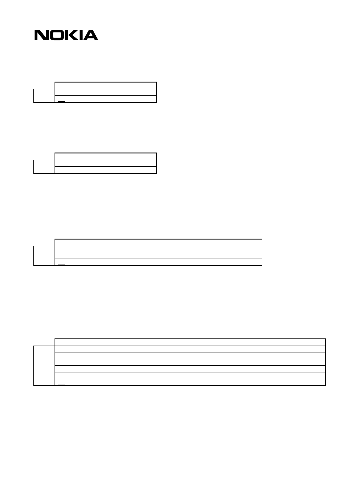
3.1 Register commands
Table 2. Register command format in command
description subsections
Command Response <n> values
Set
Read
Sn=<n> x..y (default z)
Sn? <n> xxx..yyy
The register command factory default value (&F) is given in parentheses under the column ‘<n>
values’. The existence of a register command can be queried by giving a command without equal
or question marks (i.e. ATS3 returns OK, but it does not change the <n> setting). <n> cannot be
omitted when its value is set (i.e. ATS3= returns ERROR).
3.1.1 Basic commands
Table 3. Basic command format in command description
subsections
Command Description
Set/execute
CMD[x] for value x
CMDy for value y
The commands D (dial), A (answer) and O (return to online data state) include also columns for
possible result codes.
The basic command (no ‘+’ prefix) &F default value is underlined. If no value is underlined, the
setting of that command is not stored in the non-volatile memory (the command &Y is an
exception). If the command parameter is in brackets (usually zero), the parameter can be omitted.
3.1.2 Extended commands
Table 4. Extended command format in command description subsections
Command Response Default +cme error/+cms
error
Set/execute
Read
Test
+CMD[=<x>,...] [+CMD: <y>,...] [x,...] [x]
+CMD? +CMD: <z>[,...] [x]
+CMD=? [+CMD: ...] [x]
The extended command (‘+’ prefix) parameter default values are given in a separate column. If the
default value is not in brackets, the default value is the &F default value of the corresponding
parameter. When such a parameter is omitted from a command, its value remains the same as
before. If the default value is in brackets, this value shall be used when the parameter is omitted
Copyright © Nokia Mobile Phones 2001. All rights reserved.
Page 11

11
List of AT Commands for Nokia 22
from the command line. The setting of such a parameter is not stored in the memory. If a
parameter has no default value, it must always be given.
NOTE: Voice (+V) and fax (+F) commands do not exactly follow this format.
GSM commands can also return a +CME ERROR or +CMS ERROR final result code, when the
error is related to the ME or network functionality. The last column indicates whether these codes
can be returned. The presentation of +CME ERROR can be controlled with the +CMEE command.
Copyright © Nokia Mobile Phones 2001. All rights reserved.
Page 12
12
List of AT Commands for Nokia 22
4 TE-TA INTERFACE COMMANDS
4.1 V.25ter
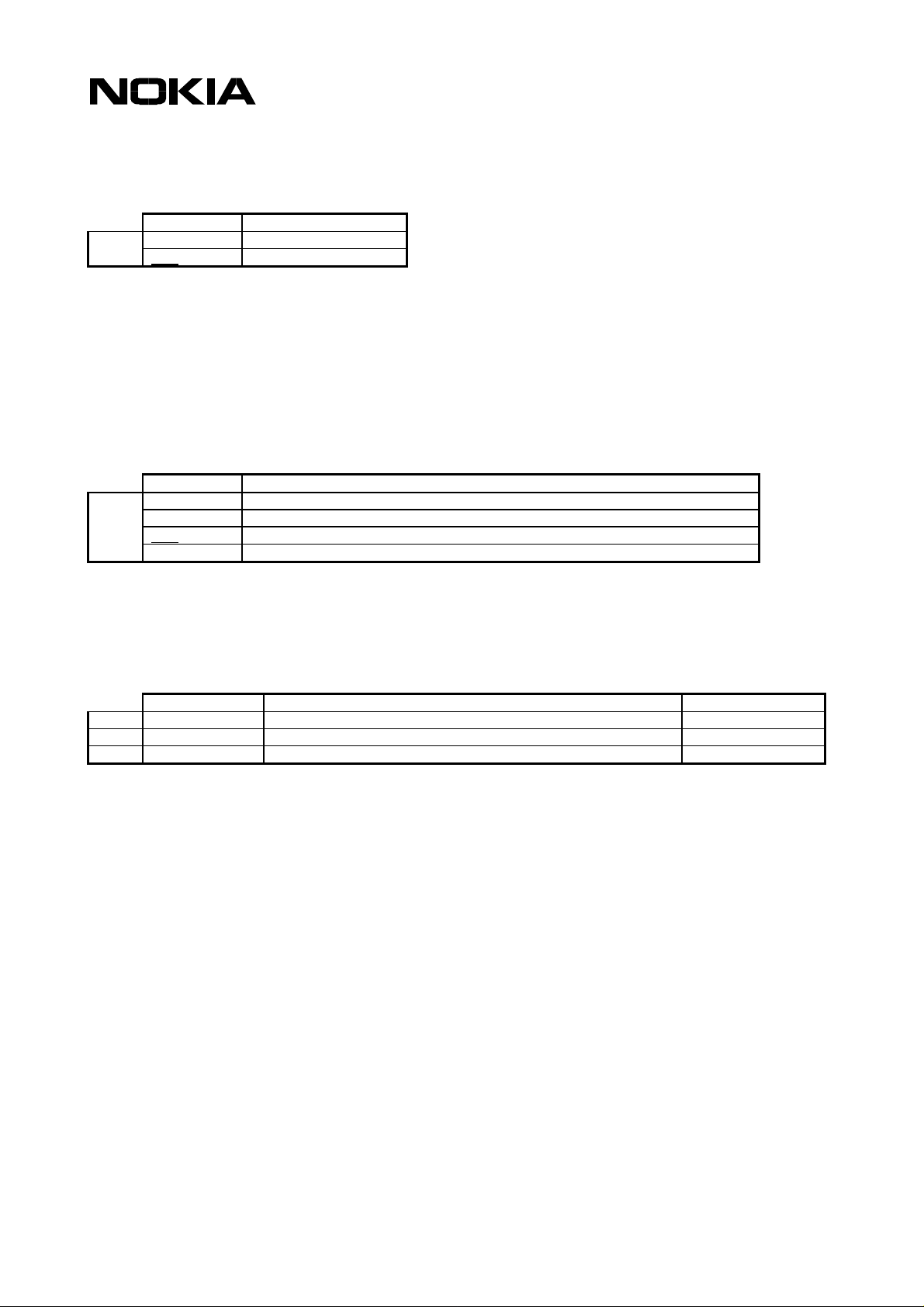
4.1.1 S3 Command line termination character
Command Response <n> values
Set
Read
S3=<n> 0..127 (default 13)
S3? <n> 000..127
The S3 command sets the decimal IA5 value of command line termination used by the DCE as a
part of the header, trailer, and terminator for result codes and information text, along with the S4
parameter (see the description of the V command for usage).
If the value of S3 is changed on a command line, the result code issued in response to that
command line will use the new value of S3. For example, if S3 was previously set to 13 and the
command line “ATS3=50” is issued, the result code issued will use the character with the ordinal
value 50 (IA5 3/2) in place of the CR.
4.1.2 S4 Response formatting character
Command Response <n> values
Set
Read
S4=<n> 0..127 (default 10)
S4? <n> 000..127
The S4 command sets the decimal IA5 value of the character generated by the DCE as a part of
the header, trailer, and terminator for result codes and information text, along with the S3
parameter (see the description of the V command for usage).
If the value of S4 is changed in a command line, the result code issued in response to that
command line will use the new value of S4.
4.1.3 S5 Command line editing character
Command response <n> values
Set
Read
S5=<n> 0..127 (default 8)
S5? <n> 000..127
The S5 command sets the decimal IA5 value of the character recognised by the DCE as a request
to delete the immediately preceding character from the command line.
Copyright © Nokia Mobile Phones 2001. All rights reserved.
Page 13
List of AT Commands for Nokia 22
4.1.4 E Command echo
Command Description
Set
E[0] no echo
E1 echo
The E command determines whether or not the DCE echoes characters received from the DTE
during the command state and the online command state.
4.1.5 Q Result code suppression
Command Description
Set
Q[0]
Q1 suppress codes
transmit codes
The Q command determines whether the DCE transmits result codes to the DTE. When result
codes are being suppressed, no portion of any intermediate, final, or unsolicited result code –
header, result text, line terminator, or trailer – is transmitted. Information text tr ansmitt ed in
response to commands is not affected by this command.
13
4.1.6 V DCE response format
Command Description
Set
V[0] numeric V.25ter basic syntax result codes, limited headers and
trailers
V1 Verbal V.25ter basic syntax result codes, full headers and trailers
The V command determines the contents of the header and trailer transmitted with result codes
and information responses. It also determines whether the result codes are transmitted in numeric
or verbal format. The text portion of information responses is not affected by this setting. The
command S3 and S4 settings affect header and trailer formatting. Note that the result codes
defined in GSM 07.07 and 07.05 have only verbal values.
4.1.7 X Result code selection and call progress monitoring control
Command Description
Set
X[0] OK, CONNECT, RING, NO CARRIER, ERROR codes enabled
X1 also CONNECT 1200, CONNECT 2400 enabled
X2 same as value 1
X3 also BUSY enabled
X4 also NO ANSWER enabled
X5 also CONNECT 4800 (or higher data rates), CARRIER, DELAYED, BLACKLISTED enabled
The X command defines the call progress result codes that are sent from the Nokia 22 to the DTE.
When BUSY, NO ANSWER, DELAYED or BLACKLISTED are not enabled, NO CARRIER is used
instead. When CONNECT <rate> with a correct data <rate> is not enabled, CONNECT is used
instead. This command only affects the presentation of the result codes mentioned in this table.
Copyright © Nokia Mobile Phones 2001. All rights reserved.
Page 14
14
List of AT Commands for Nokia 22
4.1.8 &C Circuit 109 (received line signal detector) behaviour
Command Description
Set
&C[0] always on
&C1 normal operation
The &C command determines how the state of the circuit 109 relates to the detection of a received
line signal from the distant end. Changing the parameter will take effect immediately in both
command and online command states.
In the &C1 mode of operation, the circuit 109 is on during the connection. The circuit 109 is also
known as a DCD or carrier signal.
4.1.9 &D Circuit 108 (data terminal ready) behaviour
Command Description
Set
&D[0] DTR on->off ignored
&D1 DTR on->off causes transition to on-line command state if a call is in progress
&D2 DTR on->off causes hang-up
&D3 DTR on->off causes hang-up and performs reset, like Z
The &D command determines how the DCE responds when the circuit 108/2 is changed from ON
to OFF during the online data state. The circuit 108 is also known as DTR signal.
4.1.10 +IPR Fixed DTE rate
Command Response Default
Set
Read
Test
+IPR=<rate> 0
+IPR? +IPR: <rate>
+IPR=? +IPR: (0),(9600,14400,19200,28800,38400,57600,115200)
The +IPR command sets the data rate at which the DCE will accept commands. The specified rate
takes effect immediately following the issuance of the current command line.
NOTE: The reset commands Z and &F do not change this setting.
Defined values
<rate> is the bit transmission rate in one second
Copyright © Nokia Mobile Phones 2001. All rights reserved.
Page 15

15
List of AT Commands for Nokia 22
4.1.11 +ICF DTE-DCE character framing
Command Response Default
Set
Read
Test
+ICF=<format>,<parity> [3,3]
+ICF? +ICF: <format>,<parity>
+ICF=? +ICF: (3,5),(0-3)
The +ICF command is used to determine the local serial port start-stop character framing that the
Nokia 22 uses when accepting DTE commands and when transmitting information text and a
result.
NOTE: The reset commands Z and &F do not change this setting.
Defined values
<format> determines the number of bits in the data bits, the presence of a parity bit,
and the number of stop bits in the start-stop frame.
3 8 data, 1 stop
5 7 data, 1 parity, 1 stop
<parity> determines how the parity bit is generated and checked, if present.
0 odd
1even
2mark
3 space
4.1.12 +IFC DTE-DCE local flow control
Command Response Default
Set
Read
Test
+IFC=<dce-by-dte>,<dte-by-dce> 2,2
+IFC? +IFC: <dce-by-dte>,<dte-by-dce>
+IFC=? +IFC: (0-3),(0-2)
The +IFC controls the operation of a local flow control between the DTE and the Nokia 22.
Defined values
<dce-by-dte> specifies the method to be used by the DTE to control the flow of the
received data from the Nokia 22
<dte-by-dce> specifies the method to be used by the Nokia 22 to control the flow of
the transmitted data from the DTE
0 no flow control
1 software flow control (XON/XOFF)
2 hardware flow control (RTS/CTS)
3 sof t ware flow control (XON/XOFF), with flow control characters passed also to the
remote DCE
Copyright © Nokia Mobile Phones 2001. All rights reserved.
Page 16
16
List of AT Commands for Nokia 22
4.1.13 +ILRR DTE-DCE local rate reporting
Command Response Default
Set
Read
Test
+ILRR=<n> 0
+ILRR? +ILRR: <n>
+ILRR=? +ILRR: (0,1)
The +ILRR command controls whether the extended-format “+ILRR:<rate>” information text is
transmitted from the Nokia 22 to the DTE. The <rate> reported represents the current DTE-DCE
rate. If enabled, the intermediate result code is transmitted after any error control or data
compression reports are transmitted and before any final result code (i.e. CONNECT) is
transmitted.
4.1.14 +ES Error control selection
Command Response default
set
read
test
+ES=<orig-rqst>,
<orig-fbk>,<ans-fbk>
+ES? +ES: <orig-rqst>,<orig-fbk>,<ans-fbk>
+ES=? +ES: (0-4),(0,2-4),(0-2,4-6)
4,0,2
Mandatory when the V.42 error control is implemented. See the ITU-T Recommendation V.25ter,
section 6.5.1. These settings are only used in transparent data calls (see +CBST). The supported
parameter values depend on the V.42 modes that are supported. Fallback to direct mode is not
supported by Nokia products.
4.1.15 +EB Break handling in error control operation
Command Response default
set
read
test
+EB=<break-sel>,
<timed>,<def-length>
+EB? +EB: <break-sel>,<timed>,<def-length>
+EB=? +EB: (0-3),(0,1),(0-254)
1,0,30
Mandatory when the V.42 error control is implemented. See the ITU-T Recommendation V.25ter,
section 6.5.2. These settings are only used in transparent data calls (see +CBST) with V.42
enabled (see +ES).
4.1.16 +EFCS 32-bit frame check sequence
Command response Default
set
read
test
+EFCS=<value> 0
+EFCS? +EFCS: <value>
+EFCS=? +EFCS: (0)
Mandatory when the V.42 error control is implemented. See th ITU-T Recommendation V.25ter,
section 6.5.4. Controls the use of the 32-bit frame check sequence option in the V.42 error control
mode. The 32-bit FCS is not supported by Nokia products.
Copyright © Nokia Mobile Phones 2001. All rights reserved.
Page 17

17
List of AT Commands for Nokia 22
4.1.17 +ER Error control reporting
Command response default
Set
Read
Test
+ER=<mode> 0
+ER? +ER: <mode>
+ER=? +ER: (0,1)
Mandatory when the V.42 error control is implemented. See the ITU-T Recommendation V.25ter,
section 6.5.5. Controls the presentation of the +ER intermediate result code.
4.1.18 +ETBM Call termination buffer manage
Command response default
Set
Read
Test
+ETBM=<txBuf>,<rxBuf>,<timer> 1,1,20
+ETBM? +ETBM: <txBuf>,<rxBuf>,<timer>
+ETBM=? +ETBM: (0-2),(0-2),(0-30)
Mandatory when the V.42 error control is implemented. See the ITU-T Recommendation V.25ter,
section 6.5.6. These settings may also be used in a non-transparent data call buffer management.
4.2 De facto
4.2.1 S25 Detect DTR change time
Command Response <n> values
Set
Read
S25=<n> 0..255 (default 0)
S25? <n> 000..255
The S25 command sets the time in seconds for reacting to the DTR signal change. The value 255
inhibits the signal change recognition. See also the &D command.
4.2.2 &S DSR signal behaviour
Command Description
Set
&S[0] always on
&S1 no effect
The &S command is ignored, the DSR is always ON.
4.2.3 &K Select flow control
Command Description
Set
&K[0] no flow control
&K3 hardware flow control (RTS/CTS)
&K4 software flow control (XON/XOFF)
Copyright © Nokia Mobile Phones 2001. All rights reserved.
Page 18
18
List of AT Commands for Nokia 22
The &K command changes the same setting as the +IFC. The use of +IFC is recommended.
5 GENERIC COMMANDS
5.1 V.25ter
5.1.1 Z Reset to default configuration
Command Description
Execute
Z[0] reset to stored profile 0
Z1 reset to stored profile 1
The settings that are not stored in a profile (refer to &W) will be reset to their factory defaults (refer
to &F). The implementation is according to GSM 07.07 section 5.7.
5.1.2 &F Set to factory-defined configuration
Command Description
Execute
&F[0] reset to factory
defaults
This command instructs the Nokia 22 to set default values to all parameters. The command
parameters that are reset to their factory defaults are: S3, S4, S5, E, Q, V, X, &C, &D, +IFC,
+ILRR, S25, &S, +CSCS, S0, S7, S8, S10, +DS, +DR, S2, S12, +CSTA, +CMOD, +CBST, +CRLP,
+CR, +CRC, +CSNS, +CREG, +COPS (only <format>), +CLIP, +CLIR, +COLP, +CCWA (only
<n>), +CUSD (only <n>), +CSSN, +CMER, +CPBS, +CMEE, +CSMS, +CPMS, +CMGF, +CSCA,
+CSMP, +CSDH, +CSCB, +CNMI.
5.1.3 I Request identification information
Command Response Description
Execute
I[0] Nokia Mobile Phones same as +GMI
I1 IMEI same as +GSN
I2 SWx.xx same as +GMR
I3 22 RPM-3 GSM900/1800 same as +GMM
I4..I13 Ignored values
5.1.4 +GMI Request TA manufacturer identification
Command Response
Execute
+GMI Nokia Mobile Phones
5.1.5 +GMM Request TA model identification
Command Response
Execute
+GMM 22 RPM-3 GSM900/1800
Copyright © Nokia Mobile Phones 2001. All rights reserved.
Page 19
List of AT Commands for Nokia 22
5.1.6 +GMR Request TA revision identification
Command Response
Execute
+GMR SWx.xx
5.1.7 +GSN Request TA serial number identification
Command Response
Execute
+GSN IMEI
5.1.8 +GCAP Request complete capabilities list
Command Response
Execute
+GCAP +GCAP: +CGS M, +FCLASS, +DS +ES
Defined values
19
+CGSM This is not a command to be used, but it refers to the support of the GSM 07.07 AT
command set. The implementation is according to GSM 07.07 section 5.7.
+FCLASS A command to query the support of different facsimile classes
+DS Data Compression
5.2 De facto
5.2.1 &V View configuration
Command Description
Execute
&V Show current and stored profile settings (all command parameter values defined
under &F plus &Y setting)
5.2.1.1 &W Store configuration
Command Description
Execute
&W[0] Store to profile 0
&W1 Store to profile 1
The &W command stores the current parameter values in the given profile. The command
parameters that are stored in a profile are the same as those listed under the &F command, except
for the parameters of the following commands that are not stored: +CMOD, +CSCA, +CSMP.
5.2.1.2 &Y Select power-up configuration
Command Description
Set
&Y[0] Power-up uses profile 0
&Y1 Power-up uses profile 1
The &Y command defines the profile from which parameters are loaded when the Nokia 22 is
activated. This setting is not part of the settings that are stored in a profile. The &F command does
not affect this setting.
Copyright © Nokia Mobile Phones 2001. All rights reserved.
Page 20
List of AT Commands for Nokia 22
5.3 GSM 07.07
5.3.1 +CGMI Request ME manufacturer identification
Command Response
Execute
Test
+CGMI Nokia Mobile Phones
+CGMI=?
5.3.2 +CGMM Request ME model identification
Command Response +cme error
Execute
Test
+CGMM 22 RPM-3 GSM900/1800 x
+CGMM=?
5.3.3 +CGMR Request ME revision identification
Command Response +cme error
Execute
Test
+CGMR SWx.xx x
+CGMR=?
20
5.3.4 +CGSN Request ME serial number identification
Command Response +cme error
Execute
Test
+CGSN IMEI X
+CGSN=?
5.3.5 +CSCS Select TE character set
Command Response Default
Set
Read
Test
+CSCS=<chset> "8859-1"
+CSCS? +CSCS: <chset>
+CSCS=? +CSCS: ("GSM","HEX","IRA","PCCP437","PCDN","8859-1")
The +CSCS command informs the Nokia 22 of the character set that is used by the DTE.
Defined values
<chset> DTE character set:
"GSM" GSM default alphabet (GSM 03.38 subclass 6.2.1); this setting easily causes
software flow control (XON/XOFF) problems.
"HEX" Character strings consist only of hexadecimal numbers from 00 to FF; e.g. "032FE6"
equals three 8-bit characters that in decimals are 3, 47 and 230; no conversions of
the original ME character set shall be done.
"IRA" International reference alphabet (ITU-T T.50)
"PCCP437" PC character set Code Page 437
"PCDN" PC Danish/Norwegian character set
"8859-1" ISO 8859 Latin 1 character set
Copyright © Nokia Mobile Phones 2001. All rights reserved.
Page 21
List of AT Commands for Nokia 22
5.3.6 +WS46 Select wireless network
Command Response
Set
Read
Test
+WS46=[12]
+WS46? 12
+WS46=? (12)
The +WS46 command can be used to set and query a selected or supported wireless network.
Only the value 12 ‘GSM digital cellular’ is supported.
21
Copyright © Nokia Mobile Phones 2001. All rights reserved.
Page 22

List of AT Commands for Nokia 22
6 CALL CONTROL COMMANDS
6.1 V.25ter
6.1.1 D Dial
22
Execute
Command Possible
verbose result
codes (V1)
D<dial-string> BLACKLISTED 14 Call to the number is forbidden until manual reset
BUSY 7 Called party is busy
CONNECT 1 Data/fax call established; rate 300 bps (or X forbids rate
CARRIER 16
CONNECT 1200 5 Data/fax call established; rate 1200 bps
CONNECT 2400 10 Data/fax call established; rate 2400 bps
CONNECT 4800 11 Data/fax call established; rate 4800 bps
CONNECT 9600 12 Data/fax call established; rate 9600 bps
CONNECT 14400 17 Data call established; rate 14400 bps
CONNECT 19200 18 Data call established; rate 19200 bps
CONNECT 28800 19 Data call established; rate 28800 bps
CONNECT 38400 20 Data call established; rate 38400 bps
DELAYED 13 Call to the number is temporarily forbidden
ERROR 4 Command cannot be actioned
NO ANSWER 8 Called party does not answer
NO CARRIER 3 Call could not be established
OK 0 Command aborted or voice call started with semicolon
Numeri
c (V0)
Description
display)
character
The original description of the D command is specified in the V.25ter standard, but the
implementation is according to the modifications specified in GSM 07.07. Before one of the above
codes can be returned, some of the following may precede: +CSSI, +COLP, +CR (or CARRIER),
+DR, or +ILRR (in that order). The dial command is also used to control alternating mode calls
(see GSM 07.07 section 6.6 and annexes E and F).
NOTE: The +VTS command or comma modifier (i.e. “ATD,1234”; in this case the first comma does
not cause a pause) can be used to send DTMF digits.
Copyright © Nokia Mobile Phones 2001. All rights reserved.
Page 23
List of AT Commands for Nokia 22
<dial-string> characters Values Description
V.25ter dialling digits
V.25ter modifiers
V.25ter semicolon
GSM 07.07 modifiers
De facto
0123456789+#* Accepted as valid digits (* and # can only be in the beginning)
ABCD cause ERROR
, in case of a voice call: originate call to the number preceding a
comma, wait for a remote answer, pause for a length specified with
the S8 register, and send numbers after comma as DTMF digits;
further commas cause a pause specified with S8 register (all commas
are ignored in case of data call)
T P ! W @ Accepted but ignored
; voice call originating (must be the last character of command line)
> direct dialling from the phonebook (must be the first char after D) (see
next table)
i allow calling line id presentation for this call
I restrict calling line id presentation for this call
G control CUG information for this call; use +CCUG values
L re-dial to the number last dialled
NOTE: I is the only case-sensitive dial string character.
23
Direct dialling
command
D>mem<n>[i/I][G][;]
D><n>[i/I][G][;] Originate call to the phone number in memory location <n>; the memory
Description +cme
Originate call to the phone number found in the location <n> in a specific
memory mem, which is one of the two letter memory abbreviations as returned
by +CPBS=? (without double quotes); the location range can be queried with
+CPBR=?; note that in case of a SIM ADN memory (SM), D>SIM<n> shall also
be accepted (due to inconsistency in 07.07)
selected with +CPBS is used
6.1.2 T Select tone dialling
Command
Execute
T
The T command is ignored. The implementation is according to GSM 07.07 section 6.18.
6.1.3 P Select pulse dialling
Command
Execute
P
The P command is ignored. The implementation is according to GSM 07.07 section 6.18.
error
X
X
Copyright © Nokia Mobile Phones 2001. All rights reserved.
Page 24

6.1.4 A Answer response
24
List of AT Commands for Nokia 22
Execute
CommandPossible verbose
result codes (V1)
A CONNECT 1 Data/fax call established; rate 300 bps (or X forbids rate
CONNECT 1200 5 Data / fax call established; rate 1200 bps
CONNECT 2400 10 Data / fax call established; rate 2400 bps
CONNECT 4800 11 Data / fax call established; rate 4800 bps
CONNECT 9600 12 Data / fax call established; rate 9600 bps
CONNECT 14400 17 Data call established; rate 14400 bps
CONNECT 19200 18 Data call established; rate 19200 bps
CONNECT 28800 19 Data call established; rate 28800 bps
CONNECT 38400 20 Data call established; rate 38400 bps
CONNECT 48000 21 Data call established; rate 48000 bps
CONNECT 56000 22 Data call established; rate 56000 bps
ERROR 4 Command cannot be actioned
CARRIER 16 Call will be established
NO CARRIER 3 Call could not be established
OK 0 Command aborted
Numeri
c (V0)
Description
display)
A command instructs the Nokia 22 to immediately connect to the line and to start the phone call.
Any additional commands that appear after A on the same command line are ignored.
All the result codes are not in V.25ter. Before one of the above codes can be returned, some of
the following may precede: +CR (or CARRIER), +DR, or +ILRR (in that order). The answer
command is also used to control alternating mode calls (see GSM 07.07 section 6.6).
6.1.5 H Hook control
Command Description
Execute
H[0] hang-up all calls (except possible waiting call) if only single mode calls are in
progress, or switch to voice mode if alternate mode call is active
The implementation is according to GSM 07.07 section 6.18.
Copyright © Nokia Mobile Phones 2001. All rights reserved.
Page 25
List of AT Commands for Nokia 22
6.1.6 O Return to online data state
25
Execute
Command Possible verbose
result codes (V1)
O CONNECT 1 Data/fax call established; rate 300 bps (or X forbids rate
CONNECT 1200 5 Data / fax call established; rate 1200 bps
CONNECT 2400 10 Data / fax call established; rate 2400 bps
CONNECT 4800 11 Data / fax call established; rate 4800 bps
CONNECT 9600 12 Data / fax call established; rate 9600 bps
CONNECT 14400 17 Data call established; rate 14400 bps
CONNECT 19200 18 Data call established; rate 19200 bps
CONNECT 28800 19 Data call established; rate 28800 bps
CONNECT 38400 20 Data call established; rate 38400 bps
ERROR 4 Command cannot be actioned
CARRIER 16 Call will be established
NO CARRIER 3 Call could not be established
OK 0 Command aborted
Numeri
c (V0)
Description
display)
The O command returns the Nokia 22 to the online data state from the online command mode. The
implementation is according to GSM 07.07 section 6.18.
6.1.7 S0 Automatic answer
Command Response <n> values
Set
Read
S0=<n> 0..255 (default 0)
S0? <n> 000..255
The S0 command sets the number of rings (RING or +CRING result codes) to wait before
answering automatically. 0 disables auto answering.
6.1.8 S6 Pause before blind dialling
Command Response <n> values
Set
Read
S6=<n> 2..10
S6? 002 002
The S6 command is ignored. The implementation is according to GSM 07.07 section 6.18.
6.1.9 S7 Connection completion time-out
Command Response <n> values
Set
Read
S7=<n> 0..255 (default 60)
S7? <n> 000..255
The S7 command sets the number of seconds to wait for the completion of call answering or
originating procedure before giving up and disconnecting. The implementation is according to GSM
07.07 section 6.18.
Copyright © Nokia Mobile Phones 2001. All rights reserved.
Page 26

26
List of AT Commands for Nokia 22
6.1.10 S8 Comma dial modifier time
Command Response <n> values
Set
Read
S8=<n> 0..255 (default 2)
S8? <n> 000..255
The S8 command specifies the time in seconds that the DCE shall pause during the signalling of
call addressing information to the network (dialling) when a “,” (comma) dial modifier is
encountered in a dial string of the D command. The implementation is according to GSM 07.07
section 6.18.
6.1.11 S10 Automatic disconnect delay
Command Response <n> values
Set
Read
S10=<n> 0..255 (default 100)
S10? <n> 000..255
The S10 command sets the time in tenths of a second that the Nokia 22 will remain connected to
the line (off-hook) after it has indicated the absence of the received line signal. If the received line
signal is detected before the time specified in the S10 expires, the Nokia 22 remains connected to
the line and the call continues. The implementation is according to GSM 07.07 section 6.18.
6.1.12 L Monitor speaker loudness
Command
Execute
L[0]..L3
The L command is ignored. The implementation is according to GSM 07.07 section 6.18.
6.1.13 M Monitor speaker mode
Command
Execute
M[0]..M2
The M command is ignored. The implementation is according to GSM 07.07 section 6.18.
6.1.14 +DS Data compression
Command Response Default
Set
Read
Test
+DS=<dir>,<neg>,<P1>,<P2> 0,0,2048,20
+DS? +DS: <dir>,<neg>,<P1>,<P2>
+DS=? +DS: (0-3),(0,1),(512-2048),(6-32)
The +DS command controls the V.42 bis data compression function.
NOTE: The V.42 bis data compression must be supported by the network.
Copyright © Nokia Mobile Phones 2001. All rights reserved.
Page 27
27
List of AT Commands for Nokia 22
Defined values
"dir" The desired direction(s) of the operation of the data compression function; from
the DTE's point of view:
0 Negotiated … no compression
1 Transmit only
2 Receive only
3 Both directions, accept any direction
"neg" specifies whether the DCE should continue to operate if the desired result is not
obtained:
0 Do not disconnect if Rec. V.42 bis is not negotiated by the remote DCE as specified
in <dir>
1 Disconnect if Rec. V.42 bis is not negotiated by the remote DCE as specified in <dir>
"P1" the maximum number of dictionary entries which should be negotiated
"P2" the maximum string length to be negotiated
6.1.15 +DR Data compression reporting
Command Response Default
Set
Read
Test
+DR=<mode> 0
+DR? +DR: <mode>
+DR=? +DR: (0 ,1 )
The +DR command controls the presentation of the +DR intermediate result code.
Defined values
<mode> data compression reporting:
0 disabled
1 enabled, i.e. + DR result code transmitted
6.2 De facto
6.2.1 B CCITT/Bell mode
Command
Execute
B[0]..B1
The B command is ignored.
Copyright © Nokia Mobile Phones 2001. All rights reserved.
Page 28

28
List of AT Commands for Nokia 22
6.2.2 S1 Ring count
Command Response <n> values
Read
S1? <n> 000..255
The S1 command returns the number of rings (RING or +CRING result codes) counted after the
last MT call setup.
6.2.3 S2 Escape code character
Command Response <n> values
Set
Read
S2=<n> 0..127 (default 43)
S2? <n> 000..127
The S2 command specifies the character to be used in the escape sequence. The default
character is a plus sign. See also the +++ Escape command.
6.2.4 S12 Escape guard time
Command Response <n> values
Set
Read
S12=<n> 0..255 (default 50)
S12? <n> 000..255
The S12 command sets the guard time before and after the escape sequence. The value is in
fiftieths of a second (default is one second). See also the +++ Escape command.
6.2.5 +++ Escape
During the online data state, it is possible to enter the online command state by giving three same
characters (defined by S2register; default is ‘+’) in a sequence. Before and after the sequence,
there must be a pause of at least the time defined by the S12 register. By setting S12 to zero, an
escape sequence detection can be disabled.
6.3 GSM 07.07
6.3.1 +CSTA Select type of address
Command Response Default
Set
Read
Test
+CSTA=<type> 129
+CSTA? +CSTA: <type>
+CSTA=? +CSTA: (129, 145)
The +CSTA command selects the type of number according to the GSM specifications. The dial
command D always uses this setting, except for the case when the dial string includes the
international access code character (+). In this case, the type of address sent to the network
defaults to 145.
Copyright © Nokia Mobile Phones 2001. All rights reserved.
Page 29
29
List of AT Commands for Nokia 22
Defined values
<type> type of number, refer to GSM 04.08 10.5.4.7:
129 unknown/telephony
145 international/telephony
6.3.2 +CMOD Call mode
Command Response Default
Set
Read
Test
+CMOD=<mode> 0
+CMOD? +CMOD: <mode>
+CMOD=? +CMOD: (0-3)
The +CMOD command selects the call mode of the further dialling commands (D) or for the next
answering command (A). The mode can be either single or alternating. When the single mode is
selected, the call originating and hang-up procedures are similar to the procedures specified in the
ITU-T Recommendations V.25ter, T.31 and T.32. In the GSM system, voice calls can be followed
by alternating voice/data and alternating voice/fax calls.
NOTE: The +CMOD shall be set to zero after a successfully completed alternating mode call. It
shall be set to zero also after a failed answering. The power-up, factory (&F) and user resets (Z)
shall also set the value to zero. This reduces the possibility of accidentally originating or answering
alternating mode calls.
NOTE: Alternating call answering operations from an external UI may change the +CMOD values.
Defined values
<mode>:
0 single mode
1 alter nating voice/fax (teleservice 61)
2 alter nating voice/data (bearer service 61)
3 voice followed by data (bearer service 81)
6.3.3 +CHUP Hang-up call
Command
Execute
Test
+CHUP
+CHUP=?
The +CHUP is an assured procedure to terminate an alternating mode call.
Copyright © Nokia Mobile Phones 2001. All rights reserved.
Page 30

30
List of AT Commands for Nokia 22
6.3.4 Mute control +CMUT
Command Response
Set
Read
Test
+CMUT=<n> +CME ERROR: <err>
+CMUT? +CMUT: <n>
+CME ERROR: <err>
+CMUT=? +CMUT: (list of supported <n>s)
Description
This command is used to enable and disable the uplink voice muting during a voice call. The test
command returns the supported values as a compound value.
Defined values
0 mute off
1 mute on
6.3.5 Loudspeaker volume level +CLVL
Command Response Default
Set
Read
Test
+CLVL=<level>
+CLVL?
+CLVL=?
+CLVL: <level>
+CLVL: (list of supported <level>s)
Description
This command is used to select the volume of the internal loudspeaker of the ME. The test
command returns the supported values as a compound value.
Defined values
<level>: integer type value with manufacturer specific range (smallest value
represents the lowest sound level)
6.3.6 +CBST Select bearer service type
Command Response Default
Set
Read
Test
+CBST=<speed>,
<name>,<ce>
+CBST? +CBST: <speed>,<name>,<ce>
+CBST=?
+CBST: (0-7,12,14-16,34,36,38,39,43,47-51,65,66,68,70,71,75
,79-81), (0,2),(0-3)
0,0,1
0,0,1
The +CBST command selects the bearer service with a data rate and the connection element to be
used when data calls are originated. The values may also be used during a mobile terminated data
call setup, especially in the case of single numbering scheme calls (refer +CSNS).
Defined values
Copyright © Nokia Mobile Phones 2001. All rights reserved.
Page 31

31
List of AT Commands for Nokia 22
<speed>:
0 autobauding (automatic selection of the speed; this setting is possible in case of a 3.1 kHz
modem and non-transparent service)
1 300 bps (V.21)
2 1200 bps (V.22)
3 1200/75 bps (V.23)
4 2400 bps (V.22bis)
5 2400 bps (V.26ter)
6 4800 bps (V.32)
7 9600 bps (V.32)
12 9600 bps (V.34)
14 14400 bps (V.34)
15 19200 bps (V.34)
16 28800 bps (V.34)
34 1200 bps (V.120)
36 2400 bps (V.120)
38 4800 bps (V.120)
39 9600 bps (V.120)
43 14400 bps (V.120)
47 19200 bps (V.120)
48 28800 bps (V.120)
49 38400 bps (V.120)
50 48000 bps (V.120)
51 56000 bps (V.120)
65 300 bps (V.110)
66 1200 bps (V.110)
68 2400 bps (V.110 or X.31 flag stuffing)
70 4800 bps (V.110 or X.31 flag stuffing)
71 9600 bps (V.110 or X.31 flag stuffing)
75 14400 bps (V.110 or X.31 flag stuffing)
79 19200 bps (V.110 or X.31 flag stuffing)
80 28800 bps (V.110 or X.31 flag stuffing)
<name>:
0 data circuit asynchronous (UDI or 3.1 kHz modem)
2 PAD Access (asynchronous) (UDI)
<ce>:
0 transparent
1 non-transparent
2 both, transparent preferred
3 both, non-transparent preferred
Copyright © Nokia Mobile Phones 2001. All rights reserved.
Page 32

32
List of AT Commands for Nokia 22
6.3.7 +CRLP Radio link protocol
Command Response Default
Set
Read
Test
+CRLP=<iws>,<mws>
,<T1>,<N2>[,<ver>
,<T4>]
+CRLP?
+CRLP=?
61,61,48,6
+CRLP: <iws>,<mws>,<T1>,<N2><CR><LF>
+CRLP: (0-61),(0-61),(39-255),(1-255)
<CR><LF>
The +CRLP command sets the used radio link protocol (RLP) parameters when non-transparent
data calls are originated.
The read command returns the current settings.
The test command returns the values supported by the Nokia 22 as a compound value.
Defined values
<ver> : RLP version number in integer format; when version indication is not present,
it shall equal 0
<iws> Inter Working Function (IWF) to MS window size
<mws> MS to IWF window size
<T1> acknowledgement timer in units of 10 ms
<N2> retransmission attempts
<T4>: re-sequencing period in units of 10 ms
6.3.8 +CR Service reporting control
Command Response Default
Set
Read
Test
+CR=<mode> 0
+CR? +CR: <mode>
+CR=? +CR: (0 ,1 )
The +CR command controls the returning of the intermediate result code +CR: <serv>. If enabled,
the intermediate result code is transmitted during connect negotiation when the Nokia 22 has
determined the speed and quality of service that will be used, and before any error control or data
compression reports are transmitted or any final result code (e.g. CONNECT) is transmitted.
Defined values
<mode>:
0 disables reporting
1 enables reporting
<serv>:
REL ASYNC asynchronous non-transparent
Copyright © Nokia Mobile Phones 2001. All rights reserved.
Page 33

33
List of AT Commands for Nokia 22
6.3.9 +CEER Extended error report
Command Response
Execute
Test
+CEER +CEER: <report>
+CEER=?
The +CEER command returns the reason for the last call setup or in-call modification failure, or the
reason for the last last call release. <report> is the textual representation of the network cause
value as listed in GSM 04.08 annex H.
6.3.10 +CRC Cellular result codes
Command Response Default
Set
Read
Test
+CRC=<mode> 0
+CRC? +CRC: <mode>
+CRC=? +CRC: (0,1)
The +CRC command controls whether the extended format of an incoming call indication is used.
When enabled, an incoming call is indicated with the unsolicited result code +CRING: <type>
instead of the normal RING.
Defined values
<mode>:
0 disables extended format
1 enables extended format
<type>:
FAX facsimile (TS 62)
VOICE normal voice (TS 11)
VOICE/REL ASYNC voice followed by data (BS 81)
ASYNC normal data (BS 81)
REL ASYNC normal data (BS 81)
ALT VOICE/REL ASYNC alternating voice/data, voice first (BS 61)
ALT REL ASYNC/VOICE alternating voice/data, data first (BS 61)
ALT VOICE/FAX a lt ernating voice/fax, voice first (TS 61)
ALT FAX/VOICE alternating voice/fax, fax first (TS 61)
Copyright © Nokia Mobile Phones 2001. All rights reserved.
Page 34

34
List of AT Commands for Nokia 22
6.3.11 +CHSR Current call parameters reporting
Command Response Default
Set
Read
Test
+CHSR=<mode>
+CHSR? +CHSR: <mode>
+CHSR=? +CHSR: (0,1)
1
When the CHSR=1 is set, the current HSCSD configuration is written to the terminal window every
time the HSCSD configuration has changed or a new HSCSD call has been initiated. To disable
the feature, key in at+chsr=0.
6.3.12 +CSNS Single numbering scheme
Command Response Default
Set
Read
Test
+CSNS=<mode> 0
+CSNS? +CSNS: <mode>
+CSNS=? +CSNS: (0-7)
The +CSNS command selects the bearer or teleservice to be used when a mobile terminated
single numbering scheme call is established, i.e. when a call without bearer capability element is
received.
The parameter values set with the +CBST command shall be used when <mode> equals a data
service. If the +CBST parameter is set to a value that is not applicable to single numbering calls,
the parameter shall be mapped to the closest valid value.
Defined values
<mode>:
0voice
1 alternating voice/fax, voice first (TS 61)
2 fax (TS 62)
3 alternating voice/data, voice first (BS 61)
4 data
5 alt er nating voice/fax, fax first (TS 61)
6 alternating voice/data, data first (BS 61)
7 voice followed by data (BS 81)
Copyright © Nokia Mobile Phones 2001. All rights reserved.
Page 35

35
List of AT Commands for Nokia 22
6.3.13 +CHSD HSCSD device parameters
Command Response +cme error
execute
test
+CHSD +CHSD: <mclass>,<maxRx>,<maxTx>,<sum>,<codings>
+CHSD=?
x
Parameters:
<mclass>: integer type; multislot class
<maxRx>: integer type; the maximum number of receive timeslots that the ME can use
<maxTx>: integer type; the maximum number of transmit timeslots that the ME can use
<sum>: integer type; the total number of receive and transmit timeslots that the ME can use at
the same time (per TDMA frame). The following applies in a HSCSD call: 1
£ (receive slots) + (transmit slots) £ <sum>
<codings> a sum of integers each representing a supported channel coding
4 9.6k full rate data traffic channel
8 14.4k full rate data traffic channel
12 both 9.6k and 14.4k supported
6.3.14 +CHSN Parameter command syntax
Command Response +cme error
execute
test
+CHSN=[<wAiur>[,<
wRx>[,<topRx>
[,<codings>]]]]
+CHSN=? +CHSN: (1-6),(1-3),(0-3),(4,8)
+CHSN: <wAiur>,<wRx>,<topRx>,<codings>
x
Description
The set command controls parameters for non-transparent HSCSD calls. Changing <topRx> or
<codings> value during a call does not affect the current call. Changing <wAiur> or <wRx> affects
the current call only if <topRx> was non-zero when a call was established.
Defined values
<wAiur>: integer type; wanted air interface user rate. The default value 0 indicates that the TA shall
calculate a proper value from the currently selected fixed network user rate (<speed>
subparameter from +CBST command), <codings>, and <wRx> (or <maxRx> from +CHSD
command if <wRx>=0). Other values:
1 9600 bps
2 14400 bps
3 19200 bps
4 28800 bps
6 43200 bps
<wRx>: integer type; wanted amount of receive timeslots. The default value 0 indicates that the TA
shall calculate a proper value from the currently selected <wAiur> and <codings>
Copyright © Nokia Mobile Phones 2001. All rights reserved.
Page 36

36
List of AT Commands for Nokia 22
<topRx>: integer type; top value for <wRx> that the user is going to request during the next
established non-transparent HSCSD call. The default value 0 indicates that the user is not
going to change <wAiur>/<wRx> during the next call
<codings>: a sum of integers each representing a channel coding that is accepted for non-
transparent HSCSD calls. The default value 0 indicates that all the supported codings are
accepted (refer +CHSD command for other values)
<codings>: is a sum of integers each representing a supported channel coding:
4 9.6k full rate data traffic channel
8 14.4k full rate data traffic channel
12 Both 9.6k and 14.4k supported
<maxAiur>: integer type; the maximum value for <wAiur> (assuming that all supported channel
codings are accepted and the maximum number of timeslots is used)
<modify>:
0 <wAiur>/<wRx> modification during call is not supported (<topRx> accepts only 0)
1 <wAiur>/<wRx> modification during call is supported by ME/TA
NOTE! The non-transparent/transparent data service shall be selected by the at+cbst command.
6.3.15 +CHSC Current call parameters
Command response
execute
test
+CHSC +CHSC: <rx>,<tx>,<aiur>,<coding>
+CHSC=?
Parameters:
<rx>: int eger type; the number of receive timeslots currently in use
<tx>: integer type; the number of transmit timeslots currently in use
<aiur>: integer type; the current air interface user rate (in case of a transparent service this
equals fixed network user rate) (Refer to the +CHSN command for the possible
values.)
<coding>: current channel coding (Refer to the +CHSD command for the possible values.)
+CVHU voice hang-up control
Copyright © Nokia Mobile Phones 2001. All rights reserved.
Page 37

List of AT Commands for Nokia 22
6.3.16 +CVHU Voice Hang Up Control
Command response default
set
read
test
+CVHU=<mode> 0
+CVHU? +CVHU: <mode>
+CVHU=? +CVHU: (0-2)
By default, NMP products should ignore the DTR drop, but disconnect on the ATH during a call
that is in the voice mode. (GSM 07.07 section 6.).
37
Copyright © Nokia Mobile Phones 2001. All rights reserved.
Page 38

38
List of AT Commands for Nokia 22
7 NETWO RK SERVICE COMMANDS (GSM 07.07)
7.1 +CNUM Subscriber number
Command Response +cme
error
Execute
Test
+CNUM +CNUM: [<alpha1>],<number1>,<type1>
[<CR><LF>+CNUM: [<alpha2>],<number2>,<type2>
[...]]
+CNUM=?
x
The +CNUM command returns the MSISDNs related to the subscriber. This information can be
stored in the SIM. If the subscriber has different MSISDNs for different services, each MSISDN is
returned on a different line.
Defined values
<alphax> optional alphanum er ic str ing associated with <numberx>
<numberx> string type phone number of a format specified by <typex>
<typex> type of address octet in integer format (refer GSM 04.08 10.5.4.7):
145 international/telephony
129 unknown/telephony
7.2 +CREG Network registration
Command Response Default +cme
error
Set
Read
Test
+CREG=<n> 0
+CREG? +CREG: <n>,<stat>[,<lac>,<ci>] x
+CREG=? +CREG: (0-2)
The +CREG command controls the presentation of the unsolicited result code +CREG: <stat>
when <n>=1 and the ME network registration status changes, or the code +CREG:
<stat>[,<lac>,<ci>] when <n>=2 and the network cell changes.
The read command returns the status of a result code presentation and an integer <stat> which
shows whether the network has currently indicated the registration of the ME. The location
information elements <lac> and <ci> are returned only when <n>=2 and the ME is registered in the
network.
Defined values
<n>:
Copyright © Nokia Mobile Phones 2001. All rights reserved.
Page 39

39
List of AT Commands for Nokia 22
0 disable network registr ation unsolicited result code
1 enable network registr ation unsolicited result code +CREG: <stat>
2 enable network registr ation and location information unsolicited result code
+CREG: <stat>[,<lac>,<ci>]
<stat>:
0 not register ed, the ME is not currently searching for a new operator to register to
1 regist er ed, home network
2 not register ed, but ME is currently searching for a new operator to register to
3 regist ration denied
4 unknown
5 registered, roaming
<lac> string type; a two byte location area code in hexadecimal format (e.g. "00C3" equals
193 in decimal)
<ci>: string type; a two byte cell ID in hexadecimal format
7.3 +COPS Operator selection
Command Response Default +cme error
Set
Read
Test
+COPS=<mode>,
<format>,<oper>
+COPS? +COPS: <mode>[,<format>,<oper>] x
+COPS=? +COPS: [(<stat>,,,<oper>)
[,...]],,(0,1),(2)
[0,2] x
x
The +COPS command forces an attempt to select and register the GSM network operator.
<mode> is used to select whether the selection is automatically carried out by the Nokia 22 or
whether it is forced by this command to the operator <oper>, given in numeric 2 <format>. The
selected operator name format shall also apply to the further read commands (+COPS?).
The read command returns the current mode and the currently selected operator. If no operator is
selected, <format> and <oper> are omitted.
The test command returns a list of quadruplets, each representing an operator that is present in
the network. A quadruplet consists of an integer indicating the availability of the operator <stat>
and a numeric representation of the operator. The list of operators shall be in the following order:
home network, networks referenced in SIM and other networks.
After the operator list is returned, the Nokia 22 returns lists of the supported <mode>s and
<format>. These lists shall be delimited from the operator list with two commas.
Defined values
<mode>:
0 automatic (<oper> field is ignored)
1 manual (<oper> field shall be present)
Copyright © Nokia Mobile Phones 2001. All rights reserved.
Page 40

40
List of AT Commands for Nokia 22
<format>:
2 numeric <oper>
<oper> The numeric format is the GSM Location Area Identification number (refer GSM 04.08
10.5.1.3) which consists of a three BCD digit country code coded as in ITU-T E.212
Annex A, plus a two BCD digit network code, which is administration specific;
returned <oper> shall not be in Binary Coded Decimal (BCD) format, but in IRA
characters converted from BCD; hence the number has the following structure:
(country code digit 3)(country code digit 2)(country code digit 1)(network code digit
2)(network code digit 1)
<stat>:
0 unknown
1 available
2current
3 forbidden
7.4 +CLCK Facility lock
Command Response Default +cme
error
Execute
Test
+CLCK=<fac>,<mode>,
<passwd>,<class>
+CLCK=? +CLCK: ("PS","SC","AO","OI","OX",
when <mode>=2:
+CLCK: <status>[,<class1>
[<CR><LF>+CLCK: <status>,<class2>
[...]]]
"AI","IR","AB","AG","AC","FD")
[,,,7] x
The +CLCK command enables and disables or queries the state of SIM/ME security features (PIN
or security code query or fixed dialling feature) or call barring supplementary services. The <fac>
values “AB”, “AG” and “AC” are only applicable for <mode>=0. Only security code levels ‘phone’
and ‘none’ can be handled with this command. If the ‘memory’ level is set and the status is queried
(+CLCK="PS",2), the AT interface shall indicate ‘not active’ (+CLCK: 0). When the SS status
request response coming from the network indicates that the SS is active for a specific data bearer
services (e.g. ‘circuit async’), the AT interface shall only indicate ‘data’ (<class>=2) (‘not active’
case is displayed only when the SS is not active to any service; i.e. +CLCK: 0,7).
The test command returns facility values supported by the Nokia 22 as a compound value.
Defined values
<fac>:
"PS" PH-SIM (lock Phone to SIM card) (The ME asks for a password when
an other SIM card than the current SIM card is inserted; the ME may
remember certain amount of previously used cards and, therefore, it
does not necessarily ask for a password when a previously used cards
is inserted)
Copyright © Nokia Mobile Phones 2001. All rights reserved.
Page 41

41
List of AT Commands for Nokia 22
"SC" SI M (lock SIM card) (SIM asks for a password in an ME power-up and
when this lock command is issued)
"AO" BAOC (Barr All Outgoing Calls) (refer ti GSM02.88, clause 1)
"OI" BO IC (Barr Outgoing International Calls) (refer to GSM 02.88, clause 1)
"OX" BOIC-exHC (Barr Outgoing International Calls except f or Home
Country) (refer to GSM 02.88, clause 1)
"AI" BAIC (Barr All Incom ing Calls) (ref er to GSM 02.88, clause 2)
"IR" BIC-Roam (Barr Incoming Calls when Roaming outside the home
country)
(refer to GSM 02.88, clause 2)
"AB" All Barring services (refer to GSM 02.30) (applicable only for
<mode>=0)
"AG" All outgoing barring services (refer to GSM 02.30) (applicable only for
<mode>=0)
"AC" All incom ing barring services (refer to GSM 02.30) (applicable only for
<mode>=0)
"FD" SIM fixed dialling memor y feature (if the PIN2 authentication is not done
during the current session, the PIN2 is required as <passwd>)
<mode>:
0 unlock
1lock
2 query status
<status>:
0 not active
1 active
<passwd> string type; shall be the same as the password specified for the facility
from the Nokia 22 user interface or with the Change Password +CPWD
command
<classx> is a sum of integers each representing a class of information (the
default value 7 equals all classes):
1 voice (telephony)
2 data (usually refers to all bearer services; with <mode>=2 this may only
refer to some bearer service)
4 fax (f acsimile services)
Copyright © Nokia Mobile Phones 2001. All rights reserved.
Page 42
List of AT Commands for Nokia 22
7.5 +CPWD Change password
Command Response +cme
Execute
Test
+CPWD=<fac>,<oldpwd>,<newpwd> x
+CPWD=? +CPWD: ("PS",5),("SC",4),("AB",4),("P2",4)
The +CPWD command sets a new password for the facility lock function defined by the Facility
Lock +CLCK command. Note that the target lock has to be in <mode>=1.
The test command returns a list of pairs that present the available facilities and the maximum
length of their password.
Defined values
42
error
<fac>:
"PS" PH-SIM lock Phone to SIM card
"SC" SIM lock SIM card
"AB" All Barring services
"P2" SIM PIN2
<oldpwd>, <newpwd> string type; <oldpwd> shall be the same as the password
specified for the facility from the ME user interface or using the Change Password
+CPWD command. <newpwd> is the new password
7.6 +CLIP Calling line identification presentation
Command Response Default
Set
Read
Test
+CLIP=<n> 0
+CLIP? +CLIP: <n>,<m>
+CLIP=? +CLIP: (0,1)
The +CLIP command refers to the GSM supplementary service CLIP (Calling Line Identification
Presentation) that enables a called subscriber to get the calling line identity (CLI) of the calling
party when receiving a mobile terminated call. The +CLIP command enables or disables the
presentation of the CLI. It has no effect on the execution of the CLIP supplementary service in the
network.
When the presentation of the CLI is enabled (and the calling subscriber allows it), +CLIP: number>,
<type> response is returned after every RING (or +CRING: <type>; refer to "Cellular result codes
+CRC") result code.
The read command gives the status of <n> and triggers an interrogation of the provision status of
the CLIP service according GSM 02.81 (given in <m>).The test command returns the values
supported by the Nokia 22 as a compound value.
Copyright © Nokia Mobile Phones 2001. All rights reserved.
Page 43
List of AT Commands for Nokia 22
Defined values
<n> parameter sets/shows the result code presentation status in the Nokia 22:
0 disable
1 enable
<m> parameter shows the subscriber CLIP service status in the network:
0 CLIP not pr ovisioned
1 CLIP pr ovisioned
2 unk nown (e.g. no network, etc.)
<number> string type phone number of a format specified by <type>
<type> type of address octet in integer format (refer to GSM 04.08 subclause
10.5.4.7):
43
129 unknown/telephony
145 international/telephony
7.7 +CLIR Calling li ne identificati on restriction
Command Response Default
Set
Read
Test
+CLIR=<n> 0
+CLIR? +CLIR: <n>,<m>
+CLIR=? +CLIR: (0-2)
The +CLIR command refers to the CLIR-service according to GSM 02.81 that allows a calling
subscriber to enable or disable the presentation of the CLI to the called party when originating a
call.
The set command overrides the CLIR subscription when the temporary mode is provisioned as a
default adjustment for all the following outgoing calls. This adjustment can be revoked by using the
opposite command. If this command is used by a subscriber without a provision of CLIR in the
permanent mode, the network will act according GSM 02.81.
The read command gives the default adjustment for all the outgoing calls (given in <n>) and
triggers an interrogation of the provision status of the CLIR service (given in <m>).
The test command returns the supported values.
Defined values
<n> sets the adjustment for outgoing calls:
0 the presentation indicator is used according to the subscription of the
CLIR service
Copyright © Nokia Mobile Phones 2001. All rights reserved.
Page 44

List of AT Commands for Nokia 22
1 CLIR invocation
2 CLIR suppression
<m> shows the subscriber CLIR service status in the network:
0 CLIR not pr ovisioned
1 CLIR pr ovisioned in permanent mode
2 unk nown (e.g. no network, etc.)
3 CLIR tempor ary mode presentation restricted
4 CLIR t emporary mode presentation allowed
7.8 +COLP Connected line identification presentation
Command Response Default
Set
Read
Test
+COLP=<n> 0
+COLP? +COLP: <n>,<m>
+COLP=? +COLP: (0,1)
44
The +COLP command refers to the GSM supplementary service COLP (Connected Line
Identification Presentation) that enables a calling subscriber to get the connected line identity
(COL) of the called party after setting up a mobile originated call. The command enables or
disables the presentation of the COL. It has no effect on the execution of the COLR supplementary
service in the network.
When enabled (and called subscriber allows), the +COLP: <number>,<type> intermediate result
code is returned before any +CR or V.25ter responses.
The read command gives the status of <n> and triggers an interrogation of the provision status of
the COLP service according to GSM 02.81 (given in <m>).
The test command returns the supported values.
Defined values
<n> sets/shows the result code presentation status in the Nokia 22:
0 disable
1 enable
<m> shows the subscriber COLP service status in the network:
0 COLP not pr ovisioned
1 COLP pr ovisioned
2 unk nown (e.g. no network, etc.)
<number> string type phone number of a format specified by <type>
<type> type of address octet in integer format (refer GSM 04.08 subclause 10.5.4.7):
129 unknown/telephony
145 international/telephony
Copyright © Nokia Mobile Phones 2001. All rights reserved.
Page 45
45
List of AT Commands for Nokia 22
7.9 +CCWA Call waiting
Command Response Default +cme
error
Set
Read
Test
+CCWA=<n>,<mode>,<class> when <mode>=2:
+CCWA: <status>,<class1 >
[<CR><LF>+CCWA: <status>,<class2 >
[...]]
+CCWA? +CCWA: <n>
+CCWA=? +CCWA: (0,1)
0[,,7] x
The +CCWA command allows the controlling of the Call Waiting supplementary service according
to GSM 02.83. Activation, deactivation and status query are supported. When querying the status
of a network service (<mode>=2), the response line for the ‘not active’ case (<status>=0) should
be returned only if the service is not active for any <class>. The parameter <n> is used to disable
and enable the presentation of an unsolicited result code.
+CCWA: <number>,<type>,<class> when the call waiting service is enabled.
The interaction of this command with other commands based on other GSM supplementary service
is described in the GSM standard.
The test command returns the supported values.
Defined values
<n> sets/shows the result code presentation status:
0 disable
1 enable
<mode> when not given, the network is not interrogated:
0 disable
1 enable
2 query status
<classx> is a sum of integers each representing a class of information (the default
value 7 equals all classes):
1 voice (telephony)
2 data (usually refers to all bearer services; with <mode>=2 this may only
refer to some bearer services)
4 fax (f acsimile services)
<status>:
0 not active
1 active
<number> string type phone number of a calling address in the format specified by
<type>
Copyright © Nokia Mobile Phones 2001. All rights reserved.
Page 46
46
List of AT Commands for Nokia 22
<type> type of address octet in integer format (refer GSM 04.08 10.5.4.7):
129 unknown/telephony
145 international/telephony
7.10 +CUSD Unstructured supplementary service data
Command Response Default +cme
error
Set
Read
Test
+CUSD=<n>,<str>,<dcs> +CUSD: <m>[,<str>,<dcs>] 0[,,0] x
+CUSD? +CUSD: <n>
+CUSD=? +CUSD: (0,1)
The +CUSD command allows the controlling of the Unstructured Supplementary Service Data
(USSD) according to GSM 02.90. Both network and mobile initiated operations are supported. The
parameter <n> is used to disable and enable the presentation of an unsolicited result code
(network initiated operation) +CUSD: <m>,<str>,<dcs>.
When <str> is given, a mobile initiated USSD-string or a response USSD-string to a network
initiated operation is sent to the network. In the case of a successful mobile initiated operation, the
response USSD-string coming from the network is returned before the final result code.
The test command returns the supported values.
Defined values
<n> sets/shows the result code presentation status:
0 disable
1 enable
<str> string type USSD-string (when <str> parameter is not given, the network
is not interrogated):
- if <dcs> indicates that the GSM 03.38 default alphabet is used:
- if the TE character set is not "HEX" (refer to the Select TE Character
Set +CSCS command): the Nokia 22 converts GSM alphabet into the
current TE character set according to the rules of GSM 07.05, Annex A
- if the TE character set is "HEX": the Nokia 22 converts each 7-bit
character of the GSM alphabet into two IRA character long hexadecimal
numbers (e.g. character Π (GSM 23) is presented as 17 (IRA 49 and
55))
- if <dcs> indicates that a 8-bit data coding scheme is used: the Nokia
22 converts each 8-bit octet into two IRA character long hexadecimal
numbers (e.g. octet with integer value 42 is presented to the TE as two
characters 2A (IRA 50 and 65))
<dcs> GSM 03.38 Cell Broadcast Data Coding Scheme in integer
format (default 0)
Copyright © Nokia Mobile Phones 2001. All rights reserved.
Page 47
List of AT Commands for Nokia 22
<m>:
0 no further user action required (network initiated USSD-Notify, or no
further information needed after mobile initiated operation)
1 further user action required (network initiated USSD-Request, or further
information needed after mobile initiated operation)
7.11 +CSSN Supplementary service notifications
Command Response Default
Set
Read
Test
+CSSN=<n>,<m> 0,0
+CSSN? +CSSN: <n>,<m>
+CSSN=? +CSSN: (0,1),(0,1)
The +CSSN command controls the presentation of the +CSSI intermediate result code and the
+CSSU unsolicited result code.
47
The test command returns the supported values.
Defined values
<n> sets/shows the +CSSI result code presentation status:
0 disable
1 enable
<m> sets/shows the +CSSU result code presentation status:
0 disable
1 enable
7.12 +CLCC List current calls
Command Response +cme error
Execute
Test
+CLCC [+CLCC: <id1>,<dir>,<stat>,<mode>,<mpty>
[<CR><LF>+CLCC: <id2>,<dir>,<stat >,<mode>,<mpty>
[...]]]
+CLCC=?
x
The +CLCC command returns a list of current calls of the Nokia 22. If the command succeeds but
no calls are available, no information response is sent.
Defined values
<idx> integer type call identification number as described in GSM 02.30 4.5.5.1. This
number can be used in the +CHLD command operations.
Copyright © Nokia Mobile Phones 2001. All rights reserved.
Page 48

List of AT Commands for Nokia 22
<dir>:
0 mobile or iginat ed (MO) call
1 mobile t erm inated (MT) call
<stat> state of the call:
0 active
1 held
2 dialing (MO call)
3 alerting (MO call)
4 incoming (MT call)
5 waiting (MT call)
<mode> bearer/teleservice:
0voice
1 data
2fax
3 voice followed by data, voice mode
4 alternating voice/data, voice mode
5 alter nating voice/fax, voice mode
6 voice followed by data, data mode
7 alter nating voice/data, data mode
8 alternating voice/fax, fax mode
9 unknown
48
<mpty>:
0 call is not one of multipart y (conference) call parties
1 call is one of multipar t y (conference) call parties
7.13 +CCUG Closed user group
Command Response Default
set
read
test
+CCUG=<n>,<index>,<info> 0,0,0
+CCUG? +CCUG: <n>,<index>,<info>
+CCUG=?
Parameters:
<n>:
0
disable CUG temporary mode
1 enable CUG temporary mode
<index>:
0...9 CUG index
10 no index (preferred CUG taken from subscriber data)
<info>:
0 no information
1 suppress OA
2 suppress preferential CUG
3 suppress OA and preferential CUG+CCFC call forwarding number and conditions
Copyright © Nokia Mobile Phones 2001. All rights reserved.
Page 49

49
List of AT Commands for Nokia 22
7.14 +CCFC Call Forwarding Number and Conditions
Command Response default +cme error
Execute
Test
+CCFC=<reason>,
<mode>,<number>
,
<type>,<class>,
<subaddr>,
<satype>,
<time>
+CCFC=? +CCFC: (0-5)
when <mode>=2:
+CCFC: <status>,<class1>[,<number>,<type>
[,<subaddr>,<satype>[,<time>]]]
[<CR><LF>+CCFC:
<status>,<class2>[,<number>
,<type>[,<subaddr>,<satype>[,<time>]]]
[...]]
[,,,
129/145,7
,,128,20]
x
This command controls call forwarding supplementary services. The <reason> values 4 and 5 are
only applicable for <mode>=0. When the status request response from network indicates that the
SS is active for specific data bearer services (e.g. ‘circuit async’), the AT interface shall only
indicate ‘data’ (<class>=2) (the ‘not active’ case is displayed only when the SS is not active to any
service; i.e. +CCFC: 0,7).
Parameters:
<reason>:
0 unconditional
1 mobile busy
2 no reply
3 not reachable
4 all call forwarding (GSM 02.30)
5 all conditional call forwarding (GSM 02.30)
<mode>:
0 disable
1 enable
2 query st atus
3 registration
4 erasure
<number>: string type phone number of forwarding address in the format specified by <type>
<type>: type of address octet in integer format (GSM 04.08, subclause 10.5.4.7). The default
value is 145 when the dialling string includes the international access code character
"+", otherwise the default value is129
<subaddr>: string type subaddress of the format specified by <satype>
<satype>: t ype of subaddress octet in integer format (GSM 04.08, subclause 10.5.4.8). The
default value is 128.
<classx> a sum of integers each representing a class of information (the default value 7 equals
all classes):
1 voice
2 data
4 fax
Copyright © Nokia Mobile Phones 2001. All rights reserved.
Page 50

50
List of AT Commands for Nokia 22
also all other values below 128 are reserved
<time>: 1...30 when "no reply" is enabled or queried, gives the time in seconds to wait before
a call is forwarded. The default value is 20.
<status>:
0 not active
1 active
7.15 +CHLD Call related to SSs
Command response +cme error
Execute
test
+CHLD=<n>
+CHLD=? +CHLD: (0,1,1x,2,2x,3,4)
x
Optional. See ETSI GSM 07.07 /2/, section 7.12. Controls call hold, multiparty and explicit call
transfer supplementary service operations as defined in GSM 02.30, section 4.5.5.1. A short
description of <n> values: 0 = release waiting or incoming call (send ‘busy’ cause to network), or
held calls; 1 = release active calls and accept another (waiting or held) call; 1x = release active call
x; 2 = active calls on hold and accept another (waiting or held) call; 2x = active multiparty call on
hold except for call x; 3 = add a held call to a multiparty call; 4 = connect a held call to an active (or
MO alerting) call (locally both calls are disconnected).
7.16 +CAOC Advice of charge
Command response +cme error
execute
read
test
+CAOC[=<mode>] [+CAOC: <ccm>]
[+CAOC?] +CAOC: <mode>
+CAOC=? [+CAOC: (0-2)]
x
Optional. See ETSI GSM 07.07 /2/, section 7.15. Returns the current call meter value (in home
units) from the ME.
Copyright © Nokia Mobile Phones 2001. All rights reserved.
Page 51

51
List of AT Commands for Nokia 22
8 M E CONTROL AND STATUS COMMANDS (GSM 07.07)
8.1 +CPWC ME power class control
Command Response +cme error
execute
read
test
+CPWC=<class>,<band> [+CAOC: <ccm>]
+CPWC? +CPWC: <curr_class1>,
<def_class1>, <band1>
[,<curr_class2>,
<def_class2>,<band2>[...
]]
+CPWC=? +CPWC:
(0,(0,4,5)),(1,(0-2))
x
x
This command is used to set the preferred ME power class for each supported GSM frequency
band. The interaction of this setting with the selected bearer service (+CBST and HSCSD
commands) is manufacturer specific (for example, selecting a multislot operation might reduce the
power class automatically). If the setting fails in an ME error, the +CME ERROR: <err> is returned.
The read command returns the currently selected output power class and default output power
class for each supported frequency band (as defined by the ME manufacturer). The parameter
<band1> and its associated power class parameters refer to the currently used frequency band.
For example, +CPWC: 2,1,1,5,4,0 in the case of a dual-band ME currently using the band
GSM1800, for which the power class is currently set to 2, the default being class 1, and the
currently set power class value for GSM900 is class 5, the default being class 4.
The test command returns the supported bands and their power classes. For example,
+CPWC: (0,(0,4,5)),(1,(0-2)) in a case of a dual-band handheld ME.
Defined values
<class>, <curr_classn>s, <def_classn>s:
0 default (not applicable to <curr_class>s or <def_classn>s)
1… MS output power class as in GSM 05.05 [38]
<band>, <bandn>s:
0 GSM900
1 GSM1800
2 reserved for GSM1900
3
Copyright © Nokia Mobile Phones 2001. All rights reserved.
Page 52

52
List of AT Commands for Nokia 22
8.2 +CPAS Phone activity status
Command Response
Execute
Test
+CPAS +CPAS: <pas>
+CPAS=? +CPAS: (0,1,3,4)
The +CPAS command returns the activity status <pas> of the ME. It can be used to interrogate the
ME before requesting action from the phone.
The test command returns the supported values.
Defined values
<pas>:
0 ready
1 unavailable (This value is never reported.)
3ringing
4 call in prog r ess
8.3 +CFUN Set phone functi onality
Command Response Default +cme
error
Set
Read
Test
+CFUN=<fun>[,0] [0,0] x
+CFUN? +CFUN: <fun> x
+CFUN=? +CFUN: (0,1),(0)
The +CFUN command selects the level of functionality <fun> of the Nokia 22. It can be used to
stop the use of the Nokia 22 in a controlled manner. After <fun>=0, it is not possible to
communicate with the Nokia 22, but the device has to be hardware reset to establish
communication.
The test command returns supported values.
Defined values
<fun>:
0 minimum functionality
1 full f unctionalit y, t h is setting is ignored
8.4 +CPIN Enter PIN
Set
Read
Test
Command Response +cme
error
+CPIN=<pin>,<newpin> x
+CPIN? +CPIN: <code> x
+CPIN=?
Copyright © Nokia Mobile Phones 2001. All rights reserved.
Page 53

53
List of AT Commands for Nokia 22
The +CPIN command sends a password to the Nokia 22 that is required for the operating the
Nokia 22 (SIM PIN, SIM PUK, PH-SIM PIN, etc.). Note that quotation marks must be used in this
command (e.g. AT+CPIN="1234").
If the required PIN is SIM PUK or SIM PUK2, <newpin> is required. <newpin> replaces the old pin
of the SIM.
The read command returns an alphanumeric string that indicates whether a password is required.
Defined values
<pin>, <newpin> string type values
<code>:
READY ME is not pending for any password
SIM PIN ME is waiting for a SIM PIN
SIM PUK ME is waiting for a SIM PUK
PH-SIM PIN ME is waiting for a phone-to-SIM card password
PH-FSIM PIN ME is waiting for a phone-to-very first SIM card password
PH-FSIM PUK ME is waiting for a phone-to-very first SIM card unblocking password
SIM PIN2 ME is waiting for a SIM PIN2 (it is recommended that this <code> is
returned only if the last executed command resulted in a PIN2
authentication failure (i.e. +CME ERROR: 17); if the PIN2 is not entered
immediately after the failure, it is recommended that the ME should not
block its operation)
SIM PUK2 ME is waiting for a SIM PUK2 (it is recommended that this <code>
should be returned only if the last executed command resulted in a
PUK2 authentication failure (i.e. +CME ERROR: 18); if PUK2 and the
new PIN2 are not entered immediately after the failure, it is
recommended that the ME should not block its operation)
PH-NET PIN ME is waiting for a network personalisation password
PH-NET PUK ME is waiting for a network personalisation unblocking password
PH-NETSUB PIN ME is waiting for a network subset personalisation password
PH-NETSUB PUK ME is waiting for a network subset personalisation unblocking password
PH-SP PIN ME is waiting f or a service provider personalisation password
PH-SP PUK ME is waiting for a service provider personalisation unblocking
password
PH-CORP PIN ME is waiting for a corporate personalisation password
PH-CORP PUK ME is waiting f or a corporate personalisation unblocking password
8.5 +CSQ Signal quali t y
Command Response +cme error
Execute
Test
+CSQ +CSQ: <rssi>,99 x
+CSQ=? +CSQ: (0-31,99),(99)
The +CSQ command returns the received signal strength indication <rssi>.
Copyright © Nokia Mobile Phones 2001. All rights reserved.
Page 54

List of AT Commands for Nokia 22
The test command returns the supported values.
Defined values
<rssi> indicates the quality of the network coverage:
0 No network coverage
6 Nokia 22 is connected to the network
12 Satisfactory coverage
18 Good coverage
24 Excellent coverage
8.6 +CPBS Select phonebook memory storage
Command Response Default +cme error
Set
Read
Test
+CPBS=<storage> "SM"
+CPBS? +CPBS: <storage> x
+CPBS=? +CPBS: ("ME","SM","FD","ON","EN",
"MC","DC","RC")
54
The +CPBS command selects the phonebook memory storage <storage> that is used by the other
phonebook commands.
The read command returns the currently selected memory, the number of used locations and the
total number of the locations in the memory.
The test command returns the supported storages.
Defined values
<storage>:
"DC" ME dialled calls list ( + CPBW is not applicable for this stor age)
"EN" SIM (or ME) emergency number (+CPBW is not applicable for this storage)
"FD" SIM fixdialling-phonebook
"MC" ME missed (unanswered received) calls list (+CPBW not applicable for this storage)
"ME" ME phonebook
"ON" SIM (or ME) own numbers (MSISDNs) list (reading of this storage is also available
using +CNUM )
"RC" ME received calls list (+ CPBW is not applicable for this storage)
"SM" SIM phonebook
+CPBR Read phonebook entries
Command Response +cme
error
Execute
Test
+CPBR=<index1>,
<index2>
+CPBR=? +CPBR: (<index>-list),[<nlength>],[<tlength>] x
[+CPBR: <index1>,<number>,<type>,<text>[[...]
<CR><LF>+CPBR: <index2>,<number>,<type>,<text>]]
x
The +CPBR command returns phonebook entries in the location number range <index1> ...
<index2> from the current phonebook memory storage selected using the +CPBS. The entry fields
returned are the location number <indexn>, the phone number stored there <number> (of the
Copyright © Nokia Mobile Phones 2001. All rights reserved.
Page 55

55
List of AT Commands for Nokia 22
format <type>) and text <text> associated with the number. If all the queried locations are empty
(but available), no information text lines can be returned.
The test command returns the location range supported by the current storage as a compound
value and the maximum lengths of the <number> and <text> fields. In the case of a SIM storage,
the lengths may not be available.
Defined values
<index1>, <index2>, <index> Integer type values in the range of the location numbers
of the phonebook memory.
<number> string type phone number of the format <type>
<type> type of address octet in integer format (refer to GSM 04.08
10.5.4.7):
129 unknown/telephony
145 international/telephony
<text> string type field of the maximum length of <tlength>
<nlength> integer type value indicating the maximum length of the
<number> field
<tlength> integer type value indicating the maximum length of the
<text> field
8.7 +CPBF Find phonebook entries
Command Response +cme
error
Execute
Test
+CPBF=<findtext> [+CPBF: <index1>,<number>,<type>,<text>[[...]
<CR><LF>+CPBF: <index2>,<number>,<ty pe>,<text>]]
+CPBF=? +CPBF: [<nlength>],[<tlength>] x
x
The +CPBF command returns phonebook entries (from the current phonebook memory storage
selected using the +CPBS) which an alphanumeric field start with the <findtext> string. The entry
fields returned are the location number <indexn>, the phone number stored there <number> (of the
format <type>) and text <text> associated with the number. If the searched text is not found in the
entries in the current memory, the response is empty.
The test command returns the maximum lengths of the <number> and <text> fields. In the case of
a SIM storage, the lengths may not be available.
Defined values
<index1>, <index2> integer type values in the range of location numbers of the
phonebook memory
<number> string type phone number of the format <type>
<type> type of address octet in integer format (refer GSM 04.08 10.5.4.7):
129 unknown/telephony
145 international/telephony
<findtext>, <text> string type field of the maximum length of <tlength>
Copyright © Nokia Mobile Phones 2001. All rights reserved.
Page 56

56
List of AT Commands for Nokia 22
<nlength> integer type value indicating the maximum length of the <number> field
<tlength> integer type value indicating the maximum length of the <text> field
8.8 +CPBW Write phonebook entry
Command Response Default +cme
error
Execute
Test
+CPBW=<index>,<number>,
<type>,<text>
+CPBW=? +CPBW: (<index>-list),[<nlength>],
(129,145),[<tlength>]
[,,129/145] x
x
The +CPBW command writes a phonebook entry in the location number <index> in the current
phonebook memory storage selected using the +CPBS. The entry fields written are phone number
<number> in the format <type> and text <text> associated with the number. If these fields are
omitted, the phonebook entry is deleted.
The test command returns the location range supported by the current storage as a compound
value, the maximum length of the <number> field, the supported number formats of the storage,
and the maximum length of the <text> field. In the case of a SIM storage, the lengths may not be
available.
Defined values
<index> integer type values in the range of the location numbers of the phonebook
memory
<number> string type phone number of the format <type>
<type> type of address octet in integer format (refer GSM 04.08 10.5.4.7). The
default value is 145 when dialling string includes the international access code
character "+", otherwise 129:
129 unknown/telephony
145 international/telephony
<text> string type field of the maximum length of the <tlength>
<nlength> integer type value indicating the maximum length of the <number> field
<tlength> integer type value indicating the maximum length of the <text> field
Copyright © Nokia Mobile Phones 2001. All rights reserved.
Page 57

List of AT Commands for Nokia 22
8.9 +CIND Indicator control
Command Response +cme error
set
read
test
+CIND=
+CIND? +CIND: <ind>[,<ind>[,...]]
+CIND=?
Dtp2v3, CDS1.2: +CIND: ("message",(0,1)),("call",(0,1)),
("roam",(0,1)),("smsfull",(0,1))
Nokia 22: +CIND:
("message",(0,1)),("call",(0,1)),("roam",(0,1)),
("smsfull",(0,1)),("signal",(0-5))
X
X
X
Optional. See ETSI GSM 07.07 /2/, section 8.9. Queries the current status of the ME physical
indicators.
8.10 +CMER ME event reporting
Command Response Default +cme error
set
read
Test
+CMER=<mode>,<keyp>,
<disp>,<ind>[,0]
+CMER? +CMER: <mode>,<keyp>,<disp>,<ind>,0
+CMER=?
Dtp2v3, CDS1.2: +CMER:
(2),(0,2),(0),(0,1),(0)
Nokia 22 1.0: +CMER: (2,3),(0),(0),(0,1),(0)
Nokia 22: +CMER: (2,3),(0),(0),(0,1),(0)
2,0,0
,0[,0]
57
x
Mandatory when any of the +CKEV, +CDEV, or +CIEV result codes are implemented. See ETSI
GSM 07.07 /2/, section 8.10. Enables/disables the presentation of the keypad, display and
indicator unsolicited result codes.
Copyright © Nokia Mobile Phones 2001. All rights reserved.
Page 58
58
List of AT Commands for Nokia 22
9 M E ERROR COMMAND (GSM 07.07)
9.1 +CMEE Report mobile equipment error
Command Response Default
Set
Read
Test
+CMEE=<n> 0
+CMEE? +CMEE: <n>
+CMEE=? +CMEE: (0-2)
The +CMEE command disables or enables the use of the result code +CME ERROR: <err> as an
indication of an error relating to the functionality of the Nokia 22. When enabled, the ME related
errors cause the +CME ERROR: <err> final result code instead of the regular ERROR final result
code. ERROR is returned normally when an error is related to the syntax or invalid parameters.
The test command returns the supported values.
Defined values
<n>:
0 disable +CME ERROR: <err> result code and use ERROR instead
1 enable +CME ERROR: <err> result code and use numeric <err> values
2 enable +CME ERROR: <err> result code and use verbose <err> values
See also the result code +CME ERROR.
Copyright © Nokia Mobile Phones 2001. All rights reserved.
Page 59

List of AT Commands for Nokia 22
10 SMS COMMANDS (GSM 07.05)
10.1 +CSMS Select message service
Command Response Default
Set
Read
Test
+CSMS=<service> +CSMS: 1,1,1 0
+CSMS? +CSMS: <service>,1,1,1
+CSMS=? +CSMS: (0,1)
The +CSMS command selects the messaging service <service>.
The read command returns the current service setting.
The test command returns a list of all the supported services.
59
Defined values
<service>:
0 GSM 03.40 and 03.41 (the syntax of the SMS AT commands is
compatible with GSM 07.05 Phase 2, version 4.7.0; The phase 2+
features which do not require a new command syntax may be supported
(e.g. correct routing of messages with new Phase 2+ data coding
schemes)
1 GSM 03.40 and 03.41 (the syntax of the SMS AT commands is
compatible with the GSM 07.05 Phase 2+ version; the requirement of
the setting 1 is mentioned under the corresponding command
descriptions)
10.2 +CPMS Preferred message storage
Command Response Default +cms
Set
Read
Test
+CPMS=<mem1
>
,<mem2>
,<mem3>
+CPMS? +CPMS: <mem1>,<used1>,<total1>,<mem2>,
+CPMS=? +CPMS: ("ME","SM"),("ME","SM"),("SM")
+CPMS: <used1>,<total1>,<used2>,
<total2>,<used3>,<total3>
<used2>,<total2>,<mem3>,<used3>,<total3>
error
"SM","SM","SM" x
x
The +CPMS command selects the memory storage <mem1>, <mem2> and <mem3> to be used
for reading, writing, etc.
The test command returns lists of the supported memory storage.
Defined values
Copyright © Nokia Mobile Phones 2001. All rights reserved.
Page 60
60
List of AT Commands for Nokia 22
<mem1> memory from which messages are read and deleted (the commands List Messages
+CMGL, Read Message +CMGR and Delete Message +CMGD)
<mem2> memory to which writing and sending operations are made (the commands Send
Message from Storage +CMSS and Write Message to Memory +CMGW)
<mem3> memory to which received SMs are preferred to be stored (unless forwarded directly
to the TE; refer to the command New Message Indications +CNMI); the received
CBMs are always stored in the "BM" (or some manufacturer specific storage) unless
directly forwarded to the TE; the received status reports are always stored in the "SR"
(or a manufacturer specific storage) unless directly forwarded to the TE
"ME" ME message storage
"SM" S IM messag e storage
<usedx> integer type; the number of messages currently in <memx>
<totalx> integer type; the total number of message locations in <memx>
10.3 +CMGF Message format
Command Response Default
Set
Read
Test
+CMGF=<mode> 0
+CMGF? +CMGF: <mode>
+CMGF=? +CMGF: (0,1)
The +CMGF command tells the Nokia 22 the input and output format of messages to be used.
<mode> indicates the format of the messages used with the send, list, read and write commands
and the unsolicited result codes resulting from the received messages. The mode can be either the
PDU mode (entire TP data units used) or the text mode (headers and body of the messages given
as separate parameters). The text mode uses the character set specified by the command Select
TE Character Set +CSCS to be used in the message body.
The test command returns the supported modes as a compound value.
Defined values
<mode>:
0 PDU mode
1 text mode
10.4 +CSCA Service centre address
Command Response Default
Set
Read
Test
+CSCA=<sca>,<tosca> "",129
+CSCA? +CSCA: <sca>,<tosca>
+CSCA=?
Copyright © Nokia Mobile Phones 2001. All rights reserved.
Page 61
61
List of AT Commands for Nokia 22
The +CSCA command updates the SMSC address through which mobile originated SMs are
transmitted. In the text mode, the setting is used by the send and write commands. In the PDU
mode, the setting is used by the same commands, but only when the length of the SMSC address
coded into TPDU equals zero. The SMSC address may change also when the +CRES is taken
action.
The read command returns the current SMSC address settings.
Defined values
<sca> GSM 04.11 RP SC address Address-Value field in string format
<tosca> GSM 04.11 RP SC address Type-of-Address octet in integer format:
129 unknown/telephony
145 international/telephony
10.5 +CSMP Set text mode parameters
Command Response Default
Set
Read
Test
+CSMP=<fo>,<vp>,<pid>,<dcs> 17,167,0,0
+CSMP? +CSMP: <fo>,<vp>,<pid>,<dcs>
+CSMP=?
The +CSMP command is used to select values for the additional parameters needed when the SM
is sent to the network or placed in a storage when the text format message mode is selected. It is
possible to set the validity period starting from the moment when the SM is received by the SMSC
(<vp> is in range 0... 255) or to define the absolute time of the validity period termination (<vp> is a
string). The format of <vp> is given by <fo>. The values of these parameters may change also
when the +CRES is used.
NOTE: When storing a SMS-DELIV ER from the TE to t he pref erred memory storage in the text
mode (refer command Write Message to Memory +CMGW), the <vp> field can be used for <scts>.
Defined values
<fo> f irst octet of GSM 03.40 SMS-DELIVER or SMS-SUBMIT in integer format
<vp> depending on the SMS-SUBMIT <fo> setting: GSM 03.40 TP-Validity-Period either in
integer format or in time-stri n g fo rmat
<pid> GSM 03.40 TP-Protocol-Identifier in integer format
<dcs> GSM 03.38 SMS Data Coding Scheme in integer format
10.6 +CSDH Show text mode parameters
Command Response Default
Set
Read
Test
+CSDH=<show> 0
+CSDH? +CSDH: <show>
+CSDH=? +CSDH: (0,1)
Copyright © Nokia Mobile Phones 2001. All rights reserved.
Page 62
List of AT Commands for Nokia 22
The +CSDH command controls whether detailed header information is shown in the text mode
result codes.
The test command returns the supported values as a compound value.
Defined values
<show>:
0 do not show header values defined in the commands +CSCA and
+CSMP (<sca>, <tosca>, <fo>, <vp>, <pid> and <dcs>) nor <length>,
<toda> or <tooa> in the +CMT, +CMGL, +CMGR result codes for SMSDELIVERs and SMS-SUBMITs in the text mode; for SMS-COMMANDs
in the +CMGR result code, do not show <pid>, <mn>, <da>, <toda>,
<length> or <cdata>
62
1 show the values in result codes
10.7 +CSCB Select cell broadcast message types
Command Response Default +cms
Set
Read
Test
+CSCB=<mode>,<mids>,<dcss> 0,"","" x
+CSCB? +CSCB: <mode>,<mids>,<dccs>
+CSCB=? +CSCB: (0,1)
The +CSCB command defines the types of CBMs that are to be received.
The test command returns the supported modes as a compound value.
Defined values
<mode>:
0 message types specified in <mids> and <dcss> are accepted
1 message types specified in <mids> and <dcss> are not accepted
<mids> string type, all the possible combinations of GSM 03.41 CBM message
identifiers, e.g. "0,1,5,320-478,922"
error
<dcss> string type, all the possible combinations of 03.38 CBM data coding
schemes, e.g. "0-3,5”
10.8 +CSAS Save settings
Command Response Default +cms
Execute
Test
+CSAS=<profile> [1] x
+CSAS=? +CSAS: (0,1) x
Copyright © Nokia Mobile Phones 2001. All rights reserved.
error
Page 63
63
List of AT Commands for Nokia 22
The +CSAS command saves active message service settings to a non-volatile memory. The
settings specified in the commands Service Centre Address +CSCA, Set Message Parameters
+CSMP and Select Cell Broadcast Message Types +CSCB are saved. The SMSC address is not
stored if +CSCA is not set/restored during the current session (i.e. +CSCA? returns
+CSCA: "",129). The protocol id (<pid>), data coding scheme (<dcs>) and validity period (<vp>)
are not stored if the +CSMP parameter <fo> does not indicate SMS-SUBMIT (i.e. bits 1-0 are not
‘01’). In addition, the validity period is not stored if <fo> does not indicate the relative validity period
format (i.e. bits 4-3 are not ‘10’). The destination address or alpha tag cannot be stored through an
AT interface.
NOTE: The values that are not stored shall remain intact.
The test command shall display the supported profile numbers for reading and writing of settings.
10.9 +CRES Restore settings
Command Response Default +cms
error
Execute
Test
+CRES=<profile> [1] x
+CRES=? +CRES: (0,1) x
The +CRES command restores message service settings from the non-volatile memory to the
active memory. The settings specified in the commands Service Centre Address +CSCA, Set
Message Parameters +CSMP and Select Cell Broadcast Message Types +CSCB are restored. If
the protocol id, data coding scheme or validity period is restored, the +CSMP parameter <fo> is
forced to be SMS-SUBMIT (i.e. bits 1-0 are set to ‘01’). In addition, if a validity period is restored,
<fo> is forced to indicate the relative validity period format (i.e. bits 4-3 are set to ‘10’). The rest of
the <fo> bits are set to zero.
The test command shall display the supported profile numbers.
10.10 +CNMI New message indications to TE
Command Response Default +cms
error
Set
Read
Test
+CNMI=<mode>,<mt>,
<bm>,<ds>,<bfr>
+CNMI? +CNMI: <mode>,<mt>,<bm>,<ds>,<bfr>
+CNMI=? +CNMI: (0-2),(0-3),(0,2,3),(0-2),(0,1)
0,0,0,0,0 x
The +CNMI command defines the procedure for indicating the receiving of new messages from the
network to the TE when the TE is active, e.g. DTR signal is ON. If the TE is inactive (e.g. DTR
signal is OFF), message receiving should be done as specified in GSM 03.38.
<mode> controls the processing of unsolicited result codes specified within this command, <mt>
sets the result code indication routing for SMS-DELIVERs, <bm> for CBMs and <ds> for SMSSTATUS-REPORTs. <bfr> defines the handling method for buffered result codes when <mode> 1
or 2 is enabled.
The test command gives the supported setting values.
Defined values
Copyright © Nokia Mobile Phones 2001. All rights reserved.
Page 64

64
List of AT Commands for Nokia 22
<mode> the setting affects only to unsolicited result codes specified within this command:
0 Buffer unsolicited result codes in the Nokia 22. If the Nokia 22 result code buffer is
full, the oldest indications will be discarded and replaced with the new received
indications.
1 Discard indicat ion and reject new received message unsolicited result codes when
the control link is reserved (e.g. in on-line data mode). Otherwise forward them
directly to the TE.
2 Buff er unsolicit ed result codes in the Nokia 22 when the control link is reserved (e.g.
in the on-line data mode) and flush them to the TE after reservation. Otherwise
forward them directly to the TE.
NOTE: The result code buffer is in the volatile memory, messages may get lost if the
Nokia 22 is switched off before the codes are sent to TE.
<mt> The rules for storing received SMs depend on its data coding scheme (refer to GSM
03.38), preferred memory storage (+CPMS) setting, and this value:
0 No SMS-DELIVER indications are routed to the TE.
If SMS-DELIVER is stored into the Nokia 22, an indication of the memory location is
routed to the TE using an unsolicited result code: +CMTI: <mem>,<index>
1 S MS-DELIVERs (except for class 2 messages and messages in the message waiting
indication group (store message)) are routed directly to the TE using an unsolicited
result code:
+CMT: <length><CR><LF><pdu> (PDU mode enabled)
or
+CMT: <oa>,<scts>[,<tooa>,<fo>,<pid>,<dcs>,<sca>,<tosca>,
<length>]<CR><LF><data> (text mode enabled; about parameters in italics, refer to
the command Show Text Mode Parameters +CSDH)
Class 2 messages and messages in the message waiting indication
group (store message) result in an indication as defined in <mt>=1.
3 Class 3 SMS-DELIVERs are routed directly to t he TE using unsolicited result codes
defined in <mt>=2. The messages of other data coding schemes result in an
indication as defined in <mt>=1.
<bm> the rules for storing received CBMs depend on its data coding scheme (refer
GSM 03.38), the setting of the Select CBM Types (+CSCB), and this value:
0 No CBM indications are routed to the TE.
2 New CBMs are routed directly to the TE using an unsolicited result
code:
+CBM: <length><CR><LF><pdu> (PDU mode enabled)
or +CBM: <sn>,<mid>,<dcs>,<page>,<pages><CR><LF><data>
(textmode enabled)
3 Class 3 CBMs are routed directly to the TE using unsolicited result
codes defined in <bm>=2. If the CBM storage is supported, the
messages of other classes result in an indication as defined in <bm>=1.
Copyright © Nokia Mobile Phones 2001. All rights reserved.
Page 65

65
List of AT Commands for Nokia 22
<ds>:
0 No SMS-STATUS-REPORTs are routed to the TE.
1 SMS-STATUS-REPORTs are routed to the TE using an unsolicited
result code:
+CDS: <length><CR><LF><pdu> (PDU mode enabled)
or
+CDS: <fo>,<mr>,[<ra>],[<tora>],<scts>,<dt>,<st> (text mode enabled)
2 If SMS-STATUS-REPORT is stored into the Nokia 22, an indication of
the memory location is routed to the TE using an unsolicited result code:
+CDSI: <mem>,<index>
<bfr>:
0 the Nokia 22 buffer of unsolicited result codes defined within this
command is flushed to the TE when <mode> 1-2 is entered (the OK
response shall be given before flushing the codes).
1 the Nokia 22 buffer of unsolicited result codes defined within this
command is cleared when <mode> 1-2 is entered.
10.11 +CMGL List messages
Command Response Default +cms
Execute
Test
+CMGL=
<stat>
+CMGL=? Text mode (+CMGF=1):
Text mode (+CMGF=1), SMS-DELIVER or SMS-SUBMIT:
+CMGL: <index>,<stat>,<oa/da>,[<scts>]
[,<tooa/toda>,<length>]<CR><LF><data>[<CR><LF>
+CMGL: <index>,<stat>,<oa/da>,[<scts>]
[,<tooa/toda>,<length>]<CR><LF><data>[...]]
text mode (+CMGF=1), SMS-STATUS-REPORT:
+CMGL: <index>,<stat>,<fo>,<mr>,[<ra>],[<tora>],<scts>,
<dt>,<st>[<CR><LF>
+CMGL: <index>,<stat>,<fo>,<mr>,[<ra>],[<tora>],<scts>,
<dt>,<st>[...]]
text mode (+CMGF=1), SMS-COMMAND:
+CMGL: <index>,<stat>,<fo>,<ct>[<CR><LF>
+CMGL: <index>,<stat>,<fo>,<ct>[...]]
PDU mode (+CMGF=0):
+CMGL: <index>,<stat>,<length><CR><LF><pdu>
[<CR><LF>+CMGL:<index>,<stat>,<length>
<CR><LF><pdu>[...]]
+CMGL: ("REC UNREAD","ALL")
["REC
UNREA
D"/0]
error
x
PDU mode (+CMGF=0):
+CMGL: (0,4)
Text mode:
The +CMGL command returns the messages with the status value <stat> from a message storage
to the TE. If the status of the message is 'received unread', the status in the storage changes to
Copyright © Nokia Mobile Phones 2001. All rights reserved.
Page 66

66
List of AT Commands for Nokia 22
'received read'.
NOTE: If the selected <mem1> can contain different types of SMs (e.g. SMS-DELIVERs, SMSSUBMITs, SMS-STATUS-REPORTs and SMS-COMMANDs), the response may be a mix of the
responses of the different SM types. The TE application can recognise the response format by
examining the third response parameter.
The test command shall give a list of all the supported status values.
PDU mode:
The +CMGL command returns messages with the status value <stat> from the preferred message
storage <mem1> to the TE. Entire data units <pdu> are returned. If the status of the message is
'received unread', the status in the storage changes to 'received read'.
Defined values
<stat> integer type in the PDU mode (default 0), or string type in the text mode;
indicates the status of the message in the memory:
0 "REC UNREAD" r eceived unread message (i.e. new message)
1 "REC READ" r e ceived read message
2 "STO UNSENT" stored unsent message (only applicable to SMs)
3 "STO SENT" stor ed sent message (only applicable to SMs)
4 "ALL" all messages (only applicable to the +CMGL command)
<index> integer type value in the range of location numbers
<oa/da> GSM 03.40 TP-Originating/Destination-Address Address-Value field in string
format; type of address given by <tooda/toda>
<scts> GSM 03.40 TP-Service-Centre-Time-Stamp in time-string format
<tooa/toda>/<tora> GSM 04.11 TP-Originating/Destination-Address Type-of-Address
octet in integer format
129 unknown/telephony
145 internal/telephony
<length> integer type value that indicates the length of the message body <data> in
characters in the text mode (+CMGF=1); or integer type value that indicates the
length of the actual TP data unit in octets (i.e. the RP layer SMSC address octets are
not counted in the length) in the PDU mode (+CMGF=0),
<data> SMS: GSM 03.40 TP-User-Data in the text mode responses
<fo> first octet of GSM 03.40 SMS-DELIVER, SMS-SUBMIT , SMS-STATUS-
REPORT, or SMS-COMMAND in integer format
<mr> GSM 03.40 TP-Message-Reference in integer format
<ra> GSM 03.40 TP-Recipient-Address Address-Value field in string format; the type
of address is given by <tora>
Copyright © Nokia Mobile Phones 2001. All rights reserved.
Page 67

<dt> GSM 03.40 TP-Discharge-Time in time-string format: “yy/MM/dd,hh:mm:ss±zz”
<st> GSM 03.40 TP-Status in integer format
<ct> GSM 03.40 TP-Command-Type in integer format
<pdu> GSM 04.11 SC address followed by GSM 03.40 TPDU in hexadecimal format
10.12 +CMGR Read message
Command Response +cms
Execute
+CMGR=
<index>
text mode (+CMGF=1), SMS-DELIVER:
+CMGR: <stat>,<oa>,<scts>[,<tooa>,<fo>,<pid>,<dcs>,
<sca>,<tosca>,<length>]<CR><LF><data>
text mode (+CMGF=1), SMS-SUBMIT:
+CMGR: <stat>,<da>[,<toda>,<fo>,<pid>,<dcs>,[<vp>],
<sca>,<tosca>,<length>]<CR><LF><data>
text mode (+CMGF=1), SMS-STATUS-REPORT:
+CMGR: <stat>,<fo>,<mr>,[<ra>],[<tora>],<scts>,<dt>,<st>
text mode (+CMGF=1), SMS-COMMAND:
+CMGR: <stat>,<fo>,<ct>[,<pid>,[<mn>],[<da>],[<toda>],
<length><CR><LF><cdata>]
67
List of AT Commands for Nokia 22
error
x
PDU mode (+CMGF=0):
+CMGR: <stat>,<length><CR><LF><pdu>
Test
+CMGR=?
Text mode:
The +CMGR command returns a message with the location value <index> from the message
storage. If the status of the message is 'received unread', the status in the storage changes to
'received read'.
PDU mode:
The +CMGR command returns a message with the location value <index> from the preferred
message storage to the TE. The status of the message and the entire message data unit <pdu> is
returned. If the status of the message is 'received unread', the status in the storage changes to
'received read'.
Defined values
<index> integer type; value in the range of the location numbers
<stat> integer type in the PDU mode (default 0), or string type in the text mode;
indicates the status of the message in the memory:
0 "REC UNREAD" r eceived unread message (i.e. new message)
1 "REC READ" r e ceived read message
2 "STO UNSENT" stored unsent message (only applicable to SMs)
3 "STO SENT" stor ed sent message (only applicable to SMs)
4 "ALL" all messages (only applicable to the +CMGL command)
Copyright © Nokia Mobile Phones 2001. All rights reserved.
Page 68

List of AT Commands for Nokia 22
<oa>/<da> GSM 03.40 TP-Originating/Destination-Address Address-Value field in
string format; the type of address is given by <tooda>/<toda>
<scts> GSM 03.40 TP-Service-Centre-Time-Stamp in time-string format
<tooa>/<toda>/<tora> GSM 04.11 TP-Originating/Destination-Address Type-of-
Address octet in integer format
129 unknown/telephony
145 internal/telephony
<fo> first octet of GSM 03.40 SMS-DELIVER, SMS-SUBMIT , SMS-STATUS-
REPORT, or SMS-COMMAND in integer format
<pid> GSM 03.40 TP-Protocol-Identifier in integer format
<dcs> GSM 03.38 SMS Data Coding Scheme in integer format
68
<sca> GSM 04.11 RP SC address Address-Value field in string format, type of
address given by <tosca>
<tosca> GSM 04.11 RP SC address Type-of-Address octet in integer format
129 unknown/telephony
145 internal/telephony
<length> integer type value that indicates the length of the message body <data> in
characters in the text mode (+CMGF=1); or that indicates the length of the actual TP
data unit in octets (i.e. the RP layer SMSC address octets are not counted in the
length) in the PDU mode (+CMGF=0).
<data> SMS: GSM 03.40 TP-User-Data in text mode responses
<vp> GSM 03.40 TP-Validity-Period either in integer format or in time-string format
(refer <dt>)
<mr> GSM 03.40 TP-Message-Reference in integer format
<ra> GSM 03.40 TP-Recipient-Address Address-Value field in string format; type of
address given by <tora>
<dt> GSM 03.40 TP-Discharge-Time in time-string format: “yy/MM/dd,hh:mm:ss±zz”
<st> GSM 03.40 TP-Status in integer format
<ct> GSM 03.40 TP-Command-Type in integer format
<mn> GSM 03.40 TP-Message-Number in integer format
<pdu> GSM 04.11 SC address followed by GSM 03.40 TPDU in hexadecimal format
Copyright © Nokia Mobile Phones 2001. All rights reserved.
Page 69

69
List of AT Commands for Nokia 22
10.13 +CNMA New message acknowledgement to ME/TA
Command Response +cms
error
Execute
Test
text mode (+CMGF=1):
+CNMA
PDU mode (+CMGF=0):
+CNMA=<n>,<length><CR>PDU is given<ctrl-Z/ESC>
+CNMA=? PDU mode
(+CMGF=0):
+CNMA: (0-2)
x
Text mode:
The +CNMA command confirms the correct reception of a new message (SMS-DELIVER or SMS-
STATUS-REPORT) which is routed directly to the TE. This acknowledgement command (causing
the Nokia 22 to send RP-ACK to the network) shall be used when the +CSMS parameter
<service> equals 1. The Nokia 22 shall not send another +CMT or +CDS result code to the TE
before the previous one is acknowledged.
If the Nokia 22 does not get acknowledgement within the required time (network timeout), the
Nokia 22 will send a RP-ERROR to the network. Routing to the TE will automatically be disabled
by setting both <mt> and <ds> values of +CNMI to zero.
PDU mode:
The +CNMA command confirms the reception of a new message (SMS-DELIVER or SMS-
STATUS-REPORT) which is routed directly to the TE. This acknowledgement command shall be
used when the +CSMS parameter <service> equals 1. In the PDU mode, it is possible to send
either a positive (RP-ACK) or a negative (RP-ERROR) acknowledgement to the network. The
parameter <n> defines which acknowledgement will be sent. Optionally (when <length> is greater
than zero), an acknowledgement TPDU (SMS-DELIVER-REPORT for RP-ACK or RP-ERROR)
may be sent to the network. The entering of the PDU is done similarly as specified in the command
Send Message +CMGS, except that the format of <ackpdu> is used instead of <pdu> (i.e. SMSC
address field is not present). The PDU shall not be bounded by double quotes. The TA shall not
send another +CMT or +CDS result code to the TE before the previous code is acknowledged.
If the Nokia 22 does not get an acknowledgement within the required time (network timeout), the
ME should send an RP-ERROR to the network. The Nokia 22 shall automatically disable routing to
the TE by setting both <mt> and <ds> values of the +CNMI to zero.
The test command returns a list of supported <n> values. If the only value that is supported is 0,
the device does not support the sending of TPDU.
Defined values
<n>:
0 comm and operates as defined for the text mode
1 send RP-ACK ( or buffered result code received correctly)
2 send RP- ERRO R (if PDU is not given, the Nokia 22 shall send an SMS-
Copyright © Nokia Mobile Phones 2001. All rights reserved.
Page 70

DELIVER-REPORT with a GSM 03.40 TP-FCS value set to ‘FF’ (unspecified error
cause))
<length> the length of the actual TP data unit in octets (i.e. the RP layer SMSC
address octets are not counted in the length)
10.14 +CMGS Send message
Command Response Default +cms
Execute
Text mode (+CMGF=1):
+CMGS=<da>,<toda><CR>
text is entered<ctrl-Z/ESC>
List of AT Commands for Nokia 22
text mode (+CMGF=1) and sending
ok:
+CMGS: <mr>[,<scts>]
text mode:
[,129/145]
70
error
x
Test
PDU mode (+CMGF=0):
+CMGS=<length><CR>
PDU is given<ctrl-Z/ESC>
+CMGS=?
PDU mode (+CMGF=0) and sending
ok:
+CMGS: <mr>[,<ackpdu>]
Text mode:
The +CMGS command sends message to the network (SMS-SUBMIT). The message reference
value <mr> is returned to the TE when a message is successfully delivered. Optionally (when
+CSMS <service> value is 1 and the network supports), <scts> is returned. Values can be used to
identify a message upon unsolicited delivery status report result code.
PDU mode:
The +CMGS command sends a message from a TE to the network (SMS-SUBMIT). The message
reference value <mr> is returned to the TE when a message is successfully delivered. Optionally
(when +CSMS <service> value is 1 and the network supports), <ackpdu> is returned. Values can
be used to identify a message upon an unsolicited delivery status report result code.
The text/PDU entering is as specified in 07.05. If the SMSC address is not set/restored during the
current session (i.e. +CSCA? returns +CSCA: "",129), it must automatically be read from the
SIM/ME (location 1). In the PDU mode, all kinds of GSM 03.40 MO TPDUs can be sent with this
command (operation equals +CMGC).
Defined values
<da> GSM 03.40 TP-Destination-Address Address-Value field in string format; the
type of address is given by <toda>
<toda> GSM 04.11 TP-Destination-Address Type-of-Address octet in integer format
129 unknown/telephony
145 internal/telephony
<mr> GSM 03.40 TP-Message-Reference in integer format
<scts> GSM 03.40 TP-Service-Centre-Time-Stamp in time-string format
<length> the length of the actual TP data unit in octets (i.e. the RP layer SMSC
address octets are not counted in the length)
Copyright © Nokia Mobile Phones 2001. All rights reserved.
Page 71

71
List of AT Commands for Nokia 22
<ackpdu> GSM 03.40 RP-User-Data element of RP-ACK PDU
10.15 +CMSS Send message from storage
Command Response Default +cms
error
Execute
Test
+CMSS=<index>,
<da>,<toda>
+CMSS=?
text mode (+CMGF=1) and sending ok:
+CMSS: <mr>[,<scts>]
PDU mode (+CMGF=0) and sending ok:
+CMSS: <mr>[,<ackpdu>]
[,"",129/145] x
Text mode:
The +CMSS command sends a message with the location value <index> from a preferred
message storage <mem2> to the network (SMS-SUBMIT or SMS-COMMAND). If a new recipient
address <da> is given for the SMS-SUBMIT, it shall be used instead of the one stored with the
message. The reference value <mr> is returned to the TE on a successful message delivery.
Optionally (when +CSMS <service> value is 1 and network supports), <scts> is returned. Values
can be used to identify a message upon an unsolicited delivery status report result code.
PDU mode:
The +CMSS command sends a message with the location value <index> from a message storage
<mem2> to the network (SMS-SUBMIT or SMS-COMMAND). If the new recipient address <da> is
given for the SMS-SUBMIT, it shall be used instead of the one stored with the message. The
reference value <mr> is returned to the TE when a message is successfully delivered. Optionally
(when +CSMS <service> value is 1 and network supports), <ackpdu> is returned. Values can be
used to identify a message upon an unsolicited delivery status report result code.
Defined values
<index> integer type; a value in the range of the location numbers supported by the
associated memory
<da> GSM 03.40 TP-Destination-Address Address-Value field in string format; type of
address given by <toda>
<toda> GSM 04.11 TP-Destination-Address Type-of-Address octet in integer format
129 unknown/telephony
145 internal/telephony
<mr> GSM 03.40 TP-Message-Reference in integer format
<scts> GSM 03.40 TP-Service-Centre-Time-Stamp in time-string format
<ackpdu> GSM 03.40 RP-User-Data element of RP-ACK PDU
Copyright © Nokia Mobile Phones 2001. All rights reserved.
Page 72

72
List of AT Commands for Nokia 22
10.16 +CMMS More messages to send
Parameter Command Syntax
Command Possible response(s)
+CMMS=[<n>]
+CMMS? +CMMS: <n>
+CMMS=?
+CMMS: (list of supported <n>s)
Description
The set command controls the continuity of SMS relay protocol link. When the feature is enabled
(and supported by network), multiple messages can be sent much faster as the link is kept open.
The test command returns the supported values as a compound value.
Defined Values
<n>:
0 disable
1 keep enabled until the time between the response of the latest message send command
(+CMGS, +CMSS, etc.) and the next send command exceeds 1-5 seconds (the exact value
is up to the ME implementation), then the ME shall close the link and the TA automatically
switches <n> back to 0
2 enable (if the time between the response of the latest message send command and the next
send command exceeds 1-5 seconds (the exact value is up to the ME implementation), the
ME shall close the link but the TA shall not automatically switch back to <n>=0)
An example of the sending of a default alphabet message in the text mode and a SMS-STATUSREPORT is wanted:
AT+CNMI? (check that status reports are routed to TE)
+CNMI: 2,1,0,1,0
OK
AT+CSMP=32,167,0,0 (status report wanted; otherwise default settings)
OK
AT+CMGS="+358501234567" (start editing a message)
> This the first line. (edit first line and press carriage return)
> This is the last line.^Z (edit second line and send message by pressing control-Z)
+CMGS: 10 (success: message reference 10 returned from SMSC)
OK
+CDS: 2,10,"+358501234567",145,"95/07/04/13:12:14+04",
"95/07/04/13:12:20+04",0 (status report of successful message delivery received)
Storing an unsent message in the memory, sending it from there, and deleting it:
AT+CPMS? (check memory settings)
+CPMS: "ME",4,10,"ME",4,10,"ME",4,10
OK
AT+CMGW="9501231234" (write message)
> This is the message body^Z
+CMGW: 7 (index number in storage returned)
OK
AT+CMSS=7 (send from storage)
+CMSS: 12 (success: reference value 12 sent from SC)
OK
AT+CMGD=7 (delete message)
Copyright © Nokia Mobile Phones 2001. All rights reserved.
Page 73

List of AT Commands for Nokia 22
OK
10.17 +CMGW Write message to memory
Command Response Default +cms
Execute
Text mode (+CMGF=1):
+CMGW=<oa/da>,<tooa/toda>,<stat>
<CR>text is entered<ctrl-Z/ESC>
storing successful:
+CMGW: <index>
text mode:
[,129/145,
"STO UNSENT"]
73
error
x
Test
PDU mode (+CMGF=0):
+CMGW=<length>,<stat><CR>
PDU is given<ctrl-Z/ESC>
+CMGW=?
PDU mode:
[,2]
Text mode:
The +CMGW command stores a message (either SMS-DELIVER or SMS-SUBMIT) to the memory
storage <mem2>. A memory location <index> of the stored message is returned. By default, the
message status will be set to 'stored unsent', but the parameter <stat> also allows other status
values to be given. The entering of text is done similarly as specified in the command Send
Message +CMGS.
NOTE: SMS-COMMANDs and SMS-STATUS-REPORTs can not be stored in the text mode.
PDU mode:
The +CMGW command stores a message to the memory storage <mem2>. A memory location
<index> of the stored message is returned. By default, the message status will be set to 'stored
unsent', but the <stat> parameter also allows other status values to be given.
Text/PDU entering is as specified in ETSI GSM 07.05 /3/. If the SMSC address is not set/restored
during the current session (i.e. +CSCA? returns +CSCA: "",129) and the stored message is SMSSUBMIT or SMS-COMMAND, the SMSC address must automatically be read from the SIM/ME
(location 1).
Defined values
<oa>/<da> GSM 03.40 TP-Originating/Destination-Address Address-Value field in
string format; the type of address is given by <tooda>/<toda>
<scts> GSM 03.40 TP-Service-Centre-Time-Stamp in time-string format
<tooa>/<toda>/<tora> GSM 04.11 TP-Originating/Destination-Address Type-of-
Address octet in integer format
129 unknown/telephony
145 internal/telephony
<stat> integer type in the PDU mode (default 0), or string type in the text mode;
indicates the status of a message in the memory:
0 "REC UNREAD" r eceived unread message (i.e. new message)
1 "REC READ" r e ceived read message
2 "STO UNSENT" stored unsent message (only applicable to SMs)
Copyright © Nokia Mobile Phones 2001. All rights reserved.
Page 74
3 "STO SENT" stor ed sent message (only applicable to SMs)
4 "ALL" all messages (only applicable to +CMGL command)
<index> integer type; value in the range of the location numbers
<length> integer type value that indicates the length of the message body <data> in
characters in the text mode (+CMGF=1); or that indicates the length of the actual TP
data unit in octets (i.e. the RP layer SMSC address octets are not counted in the
length) in the PDU mode (+CMGF=0).
10.18 +CMGD Delete message
Command +cms error
Execute
Test
+CMGD=<index> X
+CMGD=?
74
List of AT Commands for Nokia 22
The +CMGD command deletes a message from a preferred message storage location <index>.
10.19 +CMGC Send command
Command Response Default +cms
error
Execute
Test
text mode (+CMGF=1):
+CMGC=<fo>,<ct>,<pid>,<mn>,<da>,
<toda><CR>text is entered<ctrl-Z/ESC>
PDU mode (+CMGF=0):
+CMGC=<length><CR>
PDU is given<ctrl-Z/ESC>
+CMGC=?
text mode (+CMGF=1) and sending
ok:
+CMGC: <mr>[,<scts>]
PDU mode (+CMGF=0) and
sending ok:
+CMGC: <mr>[,<ackpdu>]
text mode:
[2,0,0,
0,"",
129/145]
x
Text mode:
The +CMGC command sends a command message from a TE to the network (SMS-COMMAND).
The entering of text (GSM 03.40 TP-Command-Data) is done as specified in the command Send
Message +CMGS, but the format is fixed to be a sequence of two IRA character long hexadecimal
numbers which Nokia 22 converts into 8-bit octets. The message reference value <mr> is returned
to the TE when a message is successfully delivered. Optionally (when +CSMS <service> value is 1
and network supports), <scts> is returned. Values can be used to identify a message upon an
unsolicited delivery status report result code.
PDU mode:
The +CMGC command sends a command message from a TE to the network (SMS-COMMAND).
The message reference value <mr> is returned to the TE on a successful message delivery.
Optionally (when +CSMS <service> value is 1 and the network supports), <ackpdu> is returned.
Values can be used to identify a message upon an unsolicited delivery status report result code.
Text/PDU entering is as specified in ETSI GSM 07.05. If the SMSC address is not set/restored
during the current session (i.e. +CSCA? returns +CSCA: "",129) it must automatically be read from
Copyright © Nokia Mobile Phones 2001. All rights reserved.
Page 75

List of AT Commands for Nokia 22
the SIM/ME (location 1). In the PDU mode, all kinds of GSM 03.40 MO TPDUs can be sent with
this command (operation equals +CMGS).
Defined values
<fo> first octet of GSM 03.40 SMS-COMMAND in integer format
<ct> GSM 03.40 TP-Command-Type in integer format
<pid> GSM 03.40 TP-Protocol-Identifier in integer format
<mn> GSM 03.40 TP-Message-Number in integer format
<da> GSM 03.40 TP-Destination-Address Address-Value field in string format; the
type of address is given by <tooda>/<toda>
75
<toda> GSM 04.11 TP-Destination-Address Type-of-Address octet in integer format
129 unknown/telephony
145 internal/telephony
<mr> GSM 03.40 TP-Message-Reference in integer format
<scts> GSM 03.40 TP-Service-Centre-Time-Stamp in time-string format
<length> in the PDU mode (+CMGF=0), the length of the actual TP data unit in octets
(i.e. the RP layer SMSC address octets are not counted in the length)
<ackpdu> GSM 03.40 RP-User-Data element of RP-ACK PDU
Copyright © Nokia Mobile Phones 2001. All rights reserved.
Page 76

List of AT Commands for Nokia 22
11 VOICE COMMANDS
11.1 +VTS DTMF generation
Command Response
Execute
Test
+VTS=<dtmf>,<dtmf>,...
+VTS=? (),(),()
The +VTS command sends Dual Tone Multiple Frequency (DTMF) voices during a call. The
dialling command can also be used to send DTMFs (see the D command).
Defined values
<dtmf> DTMF digit: 0 - 9, *, #
76
Copyright © Nokia Mobile Phones 2001. All rights reserved.
Page 77
List of AT Commands for Nokia 22
12 MISCELLANEOUS COMMANDS
12.1 V.25ter
12.1.1 A/ Repeat last command line
As first chars of a command line, A/ repeats the previous command line form the Nokia 22
command line buffer. Lowercase (a/) is also accepted.
12.1.2 S47 Force fax class 2/2.0 error correction mode
Command Response <n> values
Set
Read
S47=<n> 0..2 (default 0)
S47? <n> 000..002
77
It is recommended that this command should be used when the fax ECM is implemented. The
command is used to force the ECM on, because fax software is not always capable of enabling it.
Defined values
<n>:
0 disabled
1 enabled with 64 byte frames
2 enabled with 256 byte frames
Copyright © Nokia Mobile Phones 2001. All rights reserved.
Page 78

78
List of AT Commands for Nokia 22
13 FAX COMMANDS
The following standard facsimile (+F) command sets are supported by Nokia 22 according to GSM
03.45 facsimile group 3 transparent. The specification of these commands is out of the scope of
this document. The command structures can be found in the referred standards:
- Class 1, TIA-578-A /4/
- Class 2, TIA SP-2388 /6/
- Class 2.0, TIA-592 and ITU-T T.32 /7/
In the classes 2 and 2.0, the Nokia 22 Error supports the correction mode (ECM) with 16k send
and receive buffers. The facsimile commands supported by the Nokia 22 are listed below.
13.1 TIA-578-A
+FCLASS Select, read or test Service Class
+FMI Report manufacturer identification
+FMM Request model identification
+FMR Request revision identification
+FTS Transmit silence
+FRS Receive silence
+FTM Facsimile transmit
+FRM Facsimile receive
+FTH HDLC transmit
+FRH HDLC receive
+FLO Flow control select
+FPR Serial port rate control
+FDD Double Escape Character Replacement
13.2 TIA-592
+FCLASS Select, read or test Service Class
+FMI Report manufacturer identification
+FMM Request model identification
+FMR Request revision identification
D Originate command
A Answer command
+FDT Data transmission
+FDR Data reception
+FKS Session termination
+FIP Initialise facsimile parameters
+FCC DCE capabilities parameters
+FIS Curr ent session parameters
+FCS Current session results
+FLI Local ID strings
+FPI Local polling ID strings
+FNS Non-standard frame FIF octet string
+FLP Indicate document to poll
+FSP Request to poll
Copyright © Nokia Mobile Phones 2001. All rights reserved.
Page 79

List of AT Commands for Nokia 22
+FCR Capability to receive
+FBU HDLC frame reporting
+FNR Negotiation message reporting
+FIE Procedur e interrupt enable
+FPS Page status
+FCQ Copy quality checking
+FRQ Receive quality thr esholds
+FAA Adaptive answer
+FCT DTE phase C response timeout
+FHS Call terminat ion status
+FRY ECM retry count
+FMS Minimum phase C speed
+FLO Flow control select
+FPR Serial port rate control
+FPP Packet protocol control
+FBO Data bit order
+FEA Phase C received EOL alignment
+FFC Format conversion
+FBS Buffer size
79
13.3 TIA SP-2388
+FCLASS Select, read or test Service Class
+FMFR Request manufacturer identification
+FMDL Request model identification
+FREV Request product revision identification
D Originate a call
A Answer a call
+FDT Data transmission
+FET Transmit page punctuation
+FDR Begin or continue phase C receive data
+FDCC Establish DCE capabilities
+FK Session termination
+FDIS Current session parameters
+FDCS Current session results
+FLID Local ID string
+FCIG Local polling ID string
+FLPL Indicate document to poll
+FSPL Request to poll
+FCR Capability to receive
+FBUG Session message reporting
+FECM Er r or correction mode control
+FPTS Page transfer status
+FCQ Copy quality checking
+FBADMUL Error threshold multiplier
+FBADLIN Bad line thr eshold
+FPHCTO DTE phase C response timeout
+FAXERR T.30 session error report
+FCTCRTY ECM retry count
+FMINSP Minimum phase C speed
Copyright © Nokia Mobile Phones 2001. All rights reserved.
Page 80

List of AT Commands for Nokia 22
+FTBC Phase C transmit data block size
+FRBC Phase C receive data block size
+FBOR Data bit order
+FREL Phase C received EOL alignment
+FVRFC Vertical resolution format conversion
+FDFFC Data compression format conversion
+FLNFC Page length format conversion
+FWDFC Page width format conversion
+FAA Answer parameter
+FBUF Buffer size
80
Copyright © Nokia Mobile Phones 2001. All rights reserved.
Page 81

81
List of AT Commands for Nokia 22
14 RESULT CODES
14.1 V.25ter
14.1.1 Basic syntax result codes
OK, ERROR, BUSY, CONNECT, CONNECT <rat e>, NO ANSWER, NO CARRIER: See the ITU-T
Recommendation V.25ter, section 5.7.1 and the X, D, A and O commands in this document. Note
that OK can be a result of a successful remotely initiated in-call modification from data to speech
mode, and CONNECT[<rate>] can be a result of a successful remotely initiated in-call modification
from speech to data mode. NO CARRIER can also indicate a remote hang-up of a speech call.
RING: See ETSI GSM 07.07 /2/, section 7.12. See the ITU-T Recommendation V.25ter, section
6.3.4 and the +CRC command in this document. The MT voice calls or alternating voice/data calls
starting with voice shall not result to this indication. When the RING result code is enabled
(+CRC=0), alternating MT voice/fax calls starting with voice shall automatically be switched into the
fax mode by the Nokia 22 (if +CMOD=0). Note that the RING result code is not given for waiting
calls.
14.1.2 +DR Data compression report
Format Description
+DR: <type> given when +DR=1; informs about the presence of V.42bis data compression in the established
connection
The +DR intermediate result code, if enabled, is issued after the Error Control Report (+ER) and
before the final result code (e.g. CONNECT).
Defined values
<type>:
NONE Data compression is not in use
V42B V.42 bis is in use in both directions
V42B RD V.42 bis is in use in receive direction only
V42B TD V.42 bis is in use in transmit direction only
14.1.3 +ILRR DTE-DCE local rate report
Format Description
+ILRR: <rate> given when +ILRR=1; informs about the local port rate after connection
establishment
The +ILRR intermediate result code is given after the (possible) +DR result code.
Copyright © Nokia Mobile Phones 2001. All rights reserved.
Page 82

List of AT Commands for Nokia 22
14.2 De facto
14.2.1 Call repeat restriction result codes
BLACKLISTED and DELAYED. Refer to the dialling command D and GSM 02.07, Annex A.
14.3 GSM 07.07
14.3.1 +CSSI Intermediate supplementary service notification
Format Description
+CSSI: <code> given when +CSSN=1 and some supplementary service notification is given
by network during MO call establishment
The +CSSI is the first intermediate result code after the dial command D. This result code is
enabled and disabled with the +CSSN command.
82
Defined values
<code>:
0 unconditional call f or warding is active
1 some of the conditional call forwards are active
2 call has been forwarded
3 call is waiting
5 outg oing calls ar e barred
6 incoming calls are barred
7 CLIR suppression rejected
14.3.2 +COLP Connected line identification report
Format Description
+COLP: <number>,<type> Given when +COLP=1 and number received from the network when MO call
established
The +COLP intermediate result code is given after the possible +CSSI result code. This result code
is enabled and disabled with the +COLP command.
Defined values
<number> string type phone number of the format specified by <type>
<type> type of address octet in integer format (refer GSM 04.08 subclause 10.5.4.7):
129 unknown/telephony
145 international/telephony
Copyright © Nokia Mobile Phones 2001. All rights reserved.
Page 83

83
List of AT Commands for Nokia 22
14.3.3 +CR Data service report
Format Description
+CR: REL
ASYNC
given when +CR=1 and data call established; informs about the type of data call being
established
The +CR intermediate result code is given after a possible +COLP result code during a MO data
call setup. During a MT data call setup, this is the first intermediate result code. Note that this
result code shall replace the CARRIER result code (when X5 is set). This result code is enabled
and disabled with the +CR command.
14.3.4 +CRING Distinctive ring
Format Description
+CRING: <type> Given when +CRC=1 and incoming MT call (no active or held calls in
ME)
This result code is enabled and disabled with the +CRC command.
NOTE: +CRING replaces the V.25ter RING result code.
Defined values
<type>:
FAX facsimile (TS 62)
VOICE normal voice (TS 11)
REL ASYNC normal data
ASYNC normal data
VOICE/REL ASYNC voice followed by data (BS 81)
ALT VOICE/REL ASYNC alternating voice/data, voice first (BS 61)
ALT REL ASYNC/VOICE alternating voice/data, data fir st (BS 61)
ALT VOICE/FAX alternating voice/fax, voice first (TS 61)
ALT FAX/VOICE alternating voice/fax, fax first (TS 61)
14.3.5 +CLIP Calling line identification report
Format Description
+CLIP: <number>,<type> given when +CLIP=1 and number received from network when MT
call received (no active or held calls in ME)
The +CLIP result code is sent to the TE after every RING (or +CRING) result code. This result
code is enabled and disabled with the +CLIP command.
Defined values
<number> string type phone number of a format specified by <type>
Copyright © Nokia Mobile Phones 2001. All rights reserved.
Page 84

84
List of AT Commands for Nokia 22
<type> type of address octet in integer format (refer GSM 04.08 subclause 10.5.4.7):
129 unknown/telephony
145 international/telephony
14.3.6 +CSSU Unsolicited supplementary service notification
Format Description
+CSSU: <code>[,<index>[,<number>,
<type>]]
given when +CSSN=,1 and some supplementary service notification
is given by the network during a MT call setup or during a voice call;
note that a remote release of a held call is also informed with this
result code
In the MT call setup case, the +CSSU result code is sent to the TE after every possible +CLIP
result code. In the case of a waiting call, this is given after the +CCWA result code but discarded if
the Nokia 22 is in the on-line data state. This result code is enabled and disabled with the +CSSN
command.
Defined values
<index> refer "Closed user group +CCUG"
<code>:
0 this is a forwarded call (MT call setup)
1 this is a CUG call (also <index> present) (MT call setup)
2 call has been put on hold (during a voice call)
3 call has been retrieved (dur ing a voice call)
4 mult ipar ty call entered (during a voice call)
5 call on hold has been released (this is not a SS notification) (during a
voice call)
7 call is being connecte d (alerting) with the remote party in the alerting
state in an explicit call transfer operation (during a voice call)
8 call has been connected with the other remote party in an explicit call
transfer operation (number and subaddress parameters may also be present) (during
a voice call or a MT call setup)
<number> string type phone number of a format specified by <type>
<type> type of address octet in integer format (refer to GSM 04.08, subclause
10.5.4.7):
129 unknown/telephony
145 international/telephony
14.3.7 +CCWA Call waiting
Format Description
+CCWA: <number>,<type>,<class> given when +CCWA=1 and incoming MT call is received when
there is active or held calls in the ME discarded if in the on-line
data state
Copyright © Nokia Mobile Phones 2001. All rights reserved.
Page 85

85
List of AT Commands for Nokia 22
Description
This command allows the controlling of the Call Waiting supplementary service. Activation,
deactivation and status query are supported. When querying the status of a network service
(<mode>=2), the response line for ‘not active’ case (<status>=0) should be returned only if the
service is not active for any <class>. The parameter <n> is used to disable/enable the presentation
of an unsolicited result code +CCWA: <number>,<type>,<class>[,<alpha>] to the TE when a call
waiting service is enabled. The command should be abortable when the network is interrogated.
The interaction of this command with other commands based on other GSM supplementary
services is described in the GSM standard.
The test command returns the values supported by the TA as a compound value.
Defined values
<n> (sets/shows the result code presentation status in the TA):
0 disable
1 enable
<mode> (when the <mode> parameter is not given, the network is not interrogated):
0 disable
1 enable
2 query status
<classx> is a sum of integers each representing a class of information (default 7 equals all
classes):
1 voice (telephony)
2 data (usually refer to all bearer services; with <mode>=2 this may refer only to some
bearer service)
4 fax (f acsimile services)
also all other values below 128 are reserved by this ETS
<status>:
0 not active
1 active
<number>: string type phone number of a calling address in the format specified by <type>
<type>: type of address octet in integer format (refer GSM 04.08 [8] subclause 10.5.4.7)
<alpha>: optional string type alphanumeric representation of <number> corresponding to the
entry found in the phonebook; the used character set should be the one selected with
the command Select TE Character Set +CSCS
Copyright © Nokia Mobile Phones 2001. All rights reserved.
Page 86

86
List of AT Commands for Nokia 22
14.3.8 +CREG Network registration
Format description
+CREG: <stat>[,<lac>,<cid>] when +CREG=1: given when <stat> value changes; given after NO CARRIER if
network lost when on-line
when +CREG=2: given when <stat> value changes and when network cell
(<lac> and <cid>) of the ME changes; given after NO CARRIER if network lost
when on-line
The +CREG result code is enabled and disabled with the +CREG command.
Defined values
<stat>:
0 not register ed, the ME is not currently searching for a new operator to register to
1 regist er ed, home network
2 not register ed, but ME is currently searching a new operator to register to
3 regist ration denied
4 unknown
5 registered, roaming
<lac> string type, two byte location area code in hexadecimal format (e.g. "00C3" equals
193 in decimal)
<ci> string type, two byte cell ID in hexadecimal format
14.3.9 +CUSD Network initiated unstructured supplementary service data
Format Description
+CUSD: <m>,<str>,<dcs> given when +CUSD=1 and network initiated ‘notify’ or ‘request’ USSD
message received; discarded if in the on-line data state
This result code is enabled and disabled with the +CUSD command.
NOTE: only the first ‘request’ message during a network initiated USSD session yields to the
+CUSD unsolicited result code. The rest are information responses of the +CUSD command.
Defined values
<m>:
0 no furt her user action required (network initiat ed USSD-Notify, or no further
information needed after mobile initiated operation)
1 fu rther user action requir ed (network initiated USSD-Request, or further information
needed after mobile initiat ed operat ion)
Copyright © Nokia Mobile Phones 2001. All rights reserved.
Page 87
87
List of AT Commands for Nokia 22
<str> string type USSD-string (when <str> parameter is not given, network is
not interrogated):
- if <dcs> indicates that GSM 03.38 default alphabet is used:
- if the TE character set is other than "HEX" (refer to the Select TE command)
- Character Set +CSCS): the Nokia 22 converts the GSM alphabet into current TE
character set according to the rules of GSM 07.05, Annex A
- if the TE character set is "HEX": the Nokia 22 converts each 7-bit character of the
GSM alphabet into two IRA character long hexadecimal numbers (e.g. character Π
(GSM 23) is presented as 17 (IRA 49 and 55))
- if <dcs> indicates that an 8-bit data coding scheme is used: the Nokia 22 converts
each 8-bit octet into two IRA character long hexadecimal numbers (e.g. octet with
integer value 42 is presented to the TE as two characters 2A (IRA 50 and 65))
<dcs> GSM 03.38 Cell Broadcast Data Coding Scheme in the integer format (default
0)
14.3.10 +CME ERROR Mobile equipment error
Format Description
+CME ERROR: <err> given instead of ERROR when +CMEE=1 or =2 and error is related to the ME or network
operation
Defined values
<err> see Error values section
14.4 GSM 07.05
14.4.1 +CMTI New SMS-DELIVER indication
Format Description
+CMTI: <mem>,<index> when +CNMI=0: indications are buffered into the Nokia 22
when +CNMI=1: in the on-line data state, indications are discarded; in the
command mode they are forwarded directly to the TE
when +CNMI=2: in the on-line data state, indications are buffered into the Nokia
22; in the command mode they are forwarded directly to the TE
See also the +CNMA command.
Defined values
<mem> memory to which th received SMs are preferred to be stored:
"SM" S IM messag e storage
Copyright © Nokia Mobile Phones 2001. All rights reserved.
Page 88

List of AT Commands for Nokia 22
<index> integer type, the location of the message in the defined memory
14.4.2 +CMT New SMS-DELIVER
Format Description
text mode:
+CMT: <oa>,<scts>
[,<tooa>,<fo>,<pid>,<dcs>,<sca>,
<tosca>,<length>]<CR><LF><data>
PDU mode:
+CMT: <length>
<CR><LF><pdu>
when +CNMI=0: routed messages are buffered into the Nokia 22 (if the
buffer is full, ‘memory capacity exceeded’ is sent to the network)
when +CNMI=1: in the on-line data state, the routed messages are
rejected (e.g. ‘memory capacity exceeded’ is sent to the network and
when the command mode is entered, ‘memory available’ is sent to the
network); in the command mode they are forwarded directly to the TE
when +CNMI=2: in the on-line data state, routed messages are buffered
into the Nokia 22 (if the buffer is full, ‘memory capacity exceeded’ is
sent to the network and, when the command mode is entered, ‘memory
available’ is be sent to the network); in the command mode they are
forwarded directly to the TE
88
See also +CNMA command.
Defined values
<oa> GSM 03.40 TP-Originating -Address Address-Value field in string
format; the type of address is given by <tooa>
<scts> GSM 03.40 TP-Service-Centre-Time-Stamp in time-string format
<tooa> GSM 04.11 TP-Originating -Address Type-of-Address octet in integer
format
129 unknown/telephony
145 internal/telephony
<fo> first octet of GSM 03.40 SMS-DELIVER, SMS-SUBMIT, SMS-ST ATUS-
REPORT, or SMS-COMMAND in integer format
<pid> GSM 03.40 TP-Protocol-Identifier in integer format
<dcs> GSM 03.38 SMS Data Coding Scheme in integer format
<sca> GSM 04.11 RP SC address Address-Value field in string format, type of
address given by <tosca>
<tosca> GSM 04.11 RP SC address Type-of-Address octet in integer format
129 unknown/telephony
145 internal/telephony
<length> integer type value that indicates the length of the message body <data>
in characters in the text mode (+CMGF=1); or that indicates the length
of the actual TP data unit in octets (i.e. the RP layer SMSC address
octets are not counted in the length) in the PDU mode (+CMGF=0).
Copyright © Nokia Mobile Phones 2001. All rights reserved.
Page 89

List of AT Commands for Nokia 22
<data> SMS: GSM 03.40 TP-User-Data in the text mode responses
<pdu> GSM 04.11 SC address followed by GSM 03.40 TPDU in the
hexadecimal format
14.4.3 +CBM New CBM
Format Description
text mode:
+CBM: <sn>,<mid>,<dcs>,<page>,<pages><CR><LF><data>
PDU mode:
+CBM: <length><CR><LF><pdu>
when +CNMI=0: messages are discarded
when +CNMI=1-2: messages are
forwarded directly to the TE (CBMs
cannot be received during a call)
Defined values
<sn> GSM 03.41 CBM Serial Number in integer format
89
<mid> GSM 03.41 CBM Message Identifier in integer format
<dcs> GSM 03.38 Cell Broadcast Data Coding Scheme in integer format
<page> GSM 03.41 CBM Page Parameter bits 4-7 in integer format
<pages> GSM 03.41 CBM Page Parameter bits 0-3 in integer format
<data> GSM 03.41 CBM Content of Message in text mode responses; format:
- if <dcs> indicates that GSM 03.38 default alphabet is used:
- if the TE character set is other than "HEX" (refer command +CSCS in GSM 07.07):
the Nokia 22 converts the GSM alphabet into the current TE character set according
to the rules of Annex A
- if the TE character set is "HEX": the Nokia 22 converts each 7-bit character of the
GSM alphabet into two IRA character long hexadecimal numbers
- if <dcs> indicates that an 8-bit or a UCS2 data coding scheme is used: the Nokia 22
converts each 8-bit octet into two IRA character long hexadecimal numbers
<length> the length of the actual TP data unit in octets (i.e. the RP layer SMSC
address octets are not counted in the length)
<pdu> GSM 03.41 TPDU in hexadecimal format
Copyright © Nokia Mobile Phones 2001. All rights reserved.
Page 90
List of AT Commands for Nokia 22
14.4.4 +CDSI New SMS-STATUS-REPORT indication
Format Description
+CDSI: <mem>,<index> when +CNMI=0: indications are buffered into the Nokia 22
when +CNMI=1: in the on-line data state, indications are discarded; in command
mode they are forwarded directly to the TE
when +CNMI=2: in the on-line data state, indications are buffered into the Nokia
22; in the command mode forwarded directly to the TE
Defined values
<mem> memory to which the received SMs are preferred to be stored:
"SM" S IM messag e storage
<index> integer type, the location of the message in the defined memory
90
14.4.5 +CDS New SMS-STATUS-REPORT
Format Description
text mode:
+CDS: <fo>,<mr>,[<ra>],[<tora>],
<scts>,<dt>,<st>
PDU mode:
+CDS: <length><CR><LF><pdu>
when +CNMI=0: routed messages are buffered into the Nokia 22 (if
buffer is full, ‘memory capacity exceeded’ is sent to the network)
when +CNMI=1: in the on-line data state, the routed messages are
rejected (e.g. ‘memory capacity exceeded’ is sent to the network and
when the command mode is entered, ‘memory available’ is sent to
network); in the command mode they are forwarded directly to the TE
when +CNMI=2: in the on-line data state routed, messages are buffered
into the Nokia 22 (if the buffer is full, ‘memory capacity exceeded’ is sent
to the network and when the command mode is entered, ‘memory
available’ is sent to network); in the command mode, they are forwarded
directly to the TE
See also the +CNMA command.
Defined values
<fo> first octet of GSM 03.40 SMS-STATUS-REPORT in integer format
<mr> GSM 03.40 TP-Message-Reference in integer format
<ra> G SM 03.40 TP-Recipient-Address Address-Value field in string format;
type of address given by <tora>
<tora> GSM 04.11 TP- Recipient -Address Type-of-Address octet in integer
format:
129 unknown/telephony
145 internal/telephony
<scts> GSM 03.40 TP-Service-Centre-Time-Stamp in time-string format
<dt> GSM 03.40 TP-Discharge-Time in time-string format:
“yy/MM/dd,hh:mm:ss±zz”
Copyright © Nokia Mobile Phones 2001. All rights reserved.
Page 91

List of AT Commands for Nokia 22
<st> GSM 03.40 TP-Status in integer format
<length> the length of the actual TP data unit in octets (i.e. the RP layer SMSC
address octets are not counted in the length)
<pdu> GSM 04.11 SC address followed by GSM 03.40 TPDU in hexadecimal
format
14.4.6 +CMS ERROR Message service failure
Format Description
+CMS ERROR: <err> Given instead of ERROR when error is related to ME or network
operation
Defined values
<err> see the Error values section
91
Copyright © Nokia Mobile Phones 2001. All rights reserved.
Page 92

92
List of AT Commands for Nokia 22
15 ERROR VALUES
15.1 +CME ERROR values
The columns in the following table indicate which AT commands can return the numeric <err>
value given in the topmost row. The Numbers in the cells indicate what kind of an error can
generate the <err>. The meanings of the numbers are given after the table.
An example of the +CNUM command:
Numeric error values: 1, 5, 10 - 12, 23.
The corresponding errors are: ‘external ME is not connected to TA’, ‘phone security code required
to execute the AT command’, ‘ME does not have a SIM connected to it’, 'SIM PIN required to
execute the AT command’, 'SIM PUK required to execute the AT command’.
+CGMM
+CGMR
+CGSN
D><str>
D>mem<n>
+CNUM
+CREG?
+COPS=
+COPS?
+COPS=?
+CLCK=
+CPWD=
+CCWA=
+CUSD=
+CLCC
+CFUN=
+CFUN?
+CPIN=
+CPIN?
+CSQ
+CPBS?
+CPBR=
+CPBR=?
+CPBF=
+CPBF=?
+CPBW=
+CPBW=?
Table 5. +CME error values
3 4 5 10 11 12 16 17 18 21 22 23 24 26 27 30 31 100
9 1234 78
9 1234 5, 6 8
1234 8
10 1234
1234
1234
15 1 2 3 4 11 12 8 13 23 14
1 2 3 4 11 12 8 13 23 14
1234 132314
1234 132314
123411 8
2
1234 8
1234 5 8 18
1234 8
1234 8
1234 8
24151 2 3 4 16125 8 171819
1234 8
1 phone security code required to execute the AT command
2 ME does not have a SIM connected to it
3 SIM PIN requir ed to execute the AT command
4 SIM PUK requir ed to execute the AT command
Copyright © Nokia Mobile Phones 2001. All rights reserved.
Page 93
93
List of AT Commands for Nokia 22
5 mem ory location does not exist
6 phonebook memory location is empty
7 mat ch in searched string is not found in any of the memory locations
8 g eneral memor y error; e.g. problems in SIM database communication
9 call hold/retrieve/swap/build/split/transfer/deflection failed or cannot be actioned
10 manual network selection is not possible because unavailable or forbidden network
name was given, or call is active
11 invalid password was given
12 SIM PUK2 required to execute the AT command
13 there is no network service to complete the request
14 supplementary service command failed due to an unknown error; i.e. an error that is
not covered by other <err> values
15 AT interpreter does not support the operation
16 SIM PIN2 required to execute the AT command
17 alpha entry to be stored is too long
18 number to be read/stored is too long
19 number to be stored contains characters that are not available in that memory
20 SIM interface control is not reserved or the maximum number of applications has
reserved the SIM control
22 external ME UI cannot be accessed
23 network timeout
24 entries cannot be stored in the currently selected phone book memory (e.g. on
missed calls list)
25 there is no active voice call
15.2 +CMS ERROR values
The columns in the following table indicate the SMS AT commands that can return the <err> value
given in the topmost row. The numbers in the cells indicate the error that can generate the <err>
value. The meaning of the numbers is given under the table. For details on how to read the table,
see the example in the previous section.
Table 6. +CMS error values
0-127 128-255 301 302 304 305 310 311 312 316 320 321 322 330 331
+CPMS=
+CPMS?
+CSCB=
+CSAS=
+CSAS=?
+CRES=
+CRES=?
+CNMI=
+CMGL=
+CMGR=
+CNMA=
+CMGS=
+CMSS=
+CMGW=
+CMGD=
+CMGC=
9 10 5 11 12 2 3 1 4 7 16
9 10 5141112231468 716
9 10 5 11 12 2 3 1 4 7 16
5 23146
5 23146
56
5 231468
5 23146
5 231468
5 23146
526
5 23146
5 231468
11
5 11122 3 1 4 6 13
5 231468
Copyright © Nokia Mobile Phones 2001. All rights reserved.
Page 94

94
List of AT Commands for Nokia 22
1 phone security code required to execute the AT command
2 ME does not have a SIM connected to it
3 SIM PIN requir ed to execute the AT command
4 SIM PUK requir ed to execute the AT command
5 SMS interf ace is reserved by some other application
6 g eneral memor y error; e.g. problems in the SIM database communication
7 message to be sent to the network does not contain the SMSC address and
the SMSC address cannot be found from the Nokia 22
8 mem ory location does not exist
9 RP layer cause value from the network
10 TP layer cause value from the network
11 PDU mode is enabled: the length of the given PDU is not equivalent with the given
<length> or the ME/TA detects that the PDU is of invalid format
12 text mode is enabled: too long a message is attempted to be sent/stored, or the
+CSMP does not contain a valid SMS-SUBMIT (in the case of +CMGS=), or the
ME/TAdetects that the PDU is of invalid format
13 SMS memory is full
14 <index> given in the +CMSS does not contain SMS-SUBMIT or SMS-COMMAND, or
<index> given in the +CMSS contains SMS-COMMAND and the <da> is given
16 no network service
Copyright © Nokia Mobile Phones 2001. All rights reserved.
Page 95

95
List of AT Commands for Nokia 22
16 REFERENCES
/1/ ITU-T Recommendation V.25ter: Serial asynchronous automatic dialling and control; Aug
1995.
/2/ GSM 07.07: Digital cellular telecommunications system (Phase 2+); AT command set for
GSM Mobile Equipment (ME); version 5.4.0; Nov 1997.
/3/ GSM 07.05: Digital cellular telecommunications system (Phase 2+); Use of Data Terminal
Equipment - Data Circuit terminating Equipment (DTE - DCE) interface for Short Message
Service (SMS) and Cell Broadcast Service (CBS); version 5.4.0; Nov 1997.
/4/ TIA-578-A Facsimile Digital Interfaces - Asynchronous Facsimile DCE Control Standard,
Service Class 1; May 1995.
/5/ TIA-592 Facsimile Digital Interfaces - Asynchronous Facsimile DCE Control Standard,
Service Class 2; May 1995.
/6/ TIA SP-2388: Proposed new standard - Asynchronous Facsimile DCE Control Standard; Aug
1990.
/7/ TIA PN-3131: Project to complete IS-101 Facsimile Digital Interfaces - Voice Control Inter im
Standard for Asynchronous DCE; Feb 1995.
/9/ ITU-T Recommendation G.711: Pulse code modulation (PCM) of voice frequencies; 1993.
/10/ GSM 03.40: Digital cellular telecommunications system (Phase 2+); Technical realization of
the Short Message Service (SMS); Point-to-Point (PP).
/11/ GSM 03.38: Digital cellular telecommunications system (Phase 2+); alphabets and language-
specific information.
/12/ GSM 03.41: Digital cellular telecommunications system (Phase 2+); Technical realization of
the Short Message Service Cell Broadcast (SMSCB).
/13/ ETS 300 342-1: Radio Equipment and Systems (RES); ElectroMagnetic Compatibility (EMC)
for European digital cellular telecommunications system (GSM 900 MHz and DCS 1 800
MHz).
Copyright © Nokia Mobile Phones 2001. All rights reserved.
Page 96

96
List of AT Commands for Nokia 22
17 EXAMPLE PROCEDURES ON SOME AT-COMMANDS
How to create a data call or send an SMS in text or PDU mode (and how to also check the PIN
code or signal quality).
17.1 Inputting PIN CODE
The password (PIN, security code etc.) status can be queried with the +CPIN? –command. If the
response is READY, no password is required. If the response is SIM PIN, the Nokia 22 is waiting
for a PIN code. It is possible that more than one password is needed. The following example
indicates how the PIN code is given to the Nokia 22.
How to input PIN code:
Command from the DCE Response from
Explanation
the Nokia 22
AT+CPIN?<CR> - Query about password status
+CPIN: SIM PIN PI N code requir ed
OK Previous command was succesful
AT+CPIN="1234" - Give PIN code 1234 to the Nokia 22
OK Previous command was succesful
AT+CPIN?<CR> - Query about the password status
+CPIN: READY No password required
OK Previous command was succesful
How to check network registration (signal quality):
AT+CSQ<CR> - Query signal strength.
+CQ:31, 99 Response +CSQ<rssi>, 99 (*)
(*) Values for <rss i >
0 No network coverage (Check PIN code)
1-31 Signal strenght
17.2 Initialising the Nokia 22
Command from the DCE Response
Explanation
from the
Nokia 22
AT&F<CR> - Set to factory defined configuration.
OK Previous command was succesful
AT+IFC=1,1<CR> - Set the flow control to SW flow control, the
default is HW flow control (2,2)
OK Previous command was succesful
AT&D0<CR> - Ignore DTR changes
Copyright © Nokia Mobile Phones 2001. All rights reserved.
Page 97

97
List of AT Commands for Nokia 22
OK Previous command was succesful
Making a data call with Nokia 22:
ATD+358705966200 - Start connection with dialling the preferred
number
CARRIER The Nokia 22 has a data connection to the
GSM infrastructure
CONNECT The connection to the preferred number is
established and the application can start
sending data
17.3 Sending an SMS from a terminal or other similar application
There are two different modes – the text mode and the PDU (Protocol Data Unit) mode – for
handling short messages. The default mode of the Nokia 22 is the PDU mode (+CMGF=0). A PDU
quick guide is available at www.forum.nokia.com (the Nokia 22 developer-section). The text mode
is easier to understand than the PDU mode.
AT+CMGF=0<CR> - Set the Nokia 22 to GSM 07.05 SMS PDU
mode (default).
AT+CMGS=29<CR>
>0011000C915358508181420000A7
1154747A0E4Acf41f4f29C9E769F41
21
- Send the message to the defined phone
number. The service number is not a
mandatory field in the PDU structure. This
example does not have the SMSC number.
17.4 Sending a sample SMS in the text mode
Command from the DCE Response
Explanation
from the
Nokia 22
AT+CMGF=1 - Set t h e Nokia 22 to GSM 07.05 SMS Text
mode. The default value is the PDU mode
(0).
OK Previous command was successful.
AT+CSCA="+358508771010",145- Set the SMS Service Centre number to be
used with an outgoing SMS.
OK Previous command was successful.
AT+CMGS="+358705966200",1
45<CR>My SMS<CTRL-Z>
Send the "My SMS" message to defined
phone number. 145 specifies the phone
number type.
+CMGS:
60
Data Card responses to successful sending
with Message reference number
OK Previous command was successful.
Copyright © Nokia Mobile Phones 2001. All rights reserved.
Page 98
List of AT Commands for Nokia 22
17.5 HSCSD command examples
Connection Type
Wanted air interface user
rate
9600 AT+CBST=0,0,1;+CHSN=1,0,0,0
14400 AT+CBST=0,0,1;+CHSN=2,0,0,0
19200 AT+CBST=0,0,1;+CHSN=3,0,0,0
28800 AT+CBST=0,0,1;+CHSN=4,0,0,0
43200 AT+CBST=0,0,1;+CHSN=6,0,0,0
Wanted air interface user
rate
9600 AT+CBST=81,0,1;+CHSN=1,0,0,0
14400 AT+CBST=81,0,1;+CHSN=2,0,0,0
19200 AT+CBST=81,0,1;+CHSN=3,0,0,0
28800 AT+CBST=81,0,1;+CHSN=4,0,0,0
43200 AT+CBST=81,0,1;+CHSN=6,0,0,0
31.1 kHz
Connection Type
v.110
98
Connection Type
Wanted air interface user
rate
9600 AT+CBST=51,0,1;+CHSN=1,0,0,0
14400 AT+CBST=51,0,1;+CHSN=2,0,0,0
19200 AT+CBST=51,0,1;+CHSN=3,0,0,0
28800 AT+CBST=51,0,1;+CHSN=4,0,0,0
43200 AT+CBST=51,0,1;+CHSN=6,0,0,0
v.120
Q: Can the application or terminal I am using directly receive incoming SMS?
A: The received SMS messages are stored in the SIM card memory "SM" by default. The
messages can be read from the SIM card using AT commands, e.g., the +CMGR command.
The +CNMI command (e.g. AT+CNMI=1,2,2,1,0<CR>) allows the application to receive the
incoming SMSs directly in all environments.
The following ETSI specifications can be used as a reference when the GSM 07.05 Text- and PDU
modes are used: GSM 07.05, GSM 03.03, GSM 03.38, GSM 03.40, GSM 03.41, GSM 04.11.
Q: What standards does the Nokia 22 support?
A: There are several standards that have influenced the design of the Nokia 22. From the
application's point of view, the most important standards are those that specify the AT-command
interface: ITU-T V.25ter, ETS GSM 07.07, ETS GSM 07.05, TIA-578-A, TIA-592 and TIA SP-2388.
Copyright © Nokia Mobile Phones 2001. All rights reserved.
Page 99

List of AT Commands for Nokia 22
These standards can be obtained from national standards organizations or at www.etsi.fr,
www.tiaonline.org and www.itu.ch.
99
Copyright © Nokia Mobile Phones 2001. All rights reserved.
 Loading...