

Page 1

PAMS Technical Documentation
RAE-2 Series
Chapter 6
Service SW and Tuning
Instructions
Original, 02/99
Copyright 1999. Nokia Mobile Phones. All Rights Reserved.
Page 2
RAE-2
PAMS
Service SW and Tuning Instructions
AMENDMENT RECORD SHEET
Amendment
Number
Date Inserted By Comments
02/99 Original
Technical Documentation
Page 6– 2
Original, 02/99
Page 3

PAMS
RAE-2
Technical Documentation
Service SW and Tuning Instructions
CONTENTS – Service Software
Service Software 6– 5. . . . . . . . . . . . . . . . . . . . . . . . . . . . . . . . . . . . . . . .
General 6– 5. . . . . . . . . . . . . . . . . . . . . . . . . . . . . . . . . . . . . . . . . . . . .
Hardware requirements for Windows 3.1x 6– 5. . . . . . . . . . .
Hardware requirements for Windows 95 6– 5. . . . . . . . . . . .
Software Environment of the Support Modules 6– 5. . . . . . . . .
Required Servicing Equipment 6– 6. . . . . . . . . . . . . . . . . . . . . . .
Installation 6– 7. . . . . . . . . . . . . . . . . . . . . . . . . . . . . . . . . . . . . . . .
Mechanical Connections 6– 7. . . . . . . . . . . . . . . . . . . . . . . . . .
Installing the software on PC Hard Disk 6– 7. . . . . . . . . . . . .
Common Properties of the User Interface 6– 8. . . . . . . . . . . . . . . . . .
Login Dialog 6– 8. . . . . . . . . . . . . . . . . . . . . . . . . . . . . . . . . . . . . . . . .
Main Window 6– 9. . . . . . . . . . . . . . . . . . . . . . . . . . . . . . . . . . . . . . . .
Using Help 6– 9. . . . . . . . . . . . . . . . . . . . . . . . . . . . . . . . . . . . . . . . . .
Page No
SW Update Concepts 6– 10. . . . . . . . . . . . . . . . . . . . . . . . . . . . . . . . . . .
Equipment for Nokia RAE-2 the PDA Flash programming 6– 11. . . .
Wintesla RS 6– 11. . . . . . . . . . . . . . . . . . . . . . . . . . . . . . . . . . . . . . . . .
Multimedia card 6– 12. . . . . . . . . . . . . . . . . . . . . . . . . . . . . . . . . . . . . .
Equipment for RAE–2N the CMT SW Upgrade 6– 13. . . . . . . . . . . . .
Complete Equipment for RAE–2N* the CMT SW Upgrade 6– 13.
Upgrade Equipment for RAE–2N* the CMT SW Upgrade 6– 15. .
Software Update Instructions 6– 16. . . . . . . . . . . . . . . . . . . . . . . . . . . . .
the PDA Software Upgrade 6– 16. . . . . . . . . . . . . . . . . . . . . . . . . . . . . .
Wintesla RS 6– 16. . . . . . . . . . . . . . . . . . . . . . . . . . . . . . . . . . . . . . . . .
Multimedia card 6– 17. . . . . . . . . . . . . . . . . . . . . . . . . . . . . . . . . . . . . .
Creating Flash programming Multimedia card 6– 17. . . . . . . . . .
the PDA SW uthe PDAte with Multimedia card 6– 18. . . . . . . . .
the CMT Software Upgrade 6– 19. . . . . . . . . . . . . . . . . . . . . . . . . . . . . .
General 6– 19. . . . . . . . . . . . . . . . . . . . . . . . . . . . . . . . . . . . . . . . . . . . .
Equipment Setup instructions 6– 19. . . . . . . . . . . . . . . . . . . . . . . . . .
Setting up the PC 6– 19. . . . . . . . . . . . . . . . . . . . . . . . . . . . . . . . . . . . .
Programming with Wintesla interface 6– 19. . . . . . . . . . . . . . . . . . . .
Troubleshooting for the CMT SW upgrade 6– 20. . . . . . . . . . . . . . .
RF Tuning Instructions 6– 22. . . . . . . . . . . . . . . . . . . . . . . . . . . . . . . . . . .
General 6– 22. . . . . . . . . . . . . . . . . . . . . . . . . . . . . . . . . . . . . . . . . . . . .
Required Equipment 6– 22. . . . . . . . . . . . . . . . . . . . . . . . . . . . . . . . . . . .
Equipment Setup 6– 22. . . . . . . . . . . . . . . . . . . . . . . . . . . . . . . . . . . . .
Equipment Setup for RF Tuning RAE–2 Phone
Without Removing Covers 6– 24. . . . . . . . . . . . . . . . . . . . . . . . . . .
Original, 02/99
Page 6– 3
Page 4

RAE-2
PAMS
Service SW and Tuning Instructions
Tuning RF with covers Off –using Module Jig MJS–4 6– 25. . .
Tuning EM without removing covers 6– 26. . . . . . . . . . . . . . . . . .
Tuning Steps 6– 27. . . . . . . . . . . . . . . . . . . . . . . . . . . . . . . . . . . . . . . . . . .
RX Calibration (AGC + AFC) 6– 27. . . . . . . . . . . . . . . . . . . . . . . . . . .
I/Q Modulator Amplitude Balance and Phase Shift Tuning 6– 27. .
Tuning of Transmitter Power Levels 6– 29. . . . . . . . . . . . . . . . . . . . .
Energy Management Calibration 6– 30. . . . . . . . . . . . . . . . . . . . . . . . . .
Battery & charger default values 6– 30. . . . . . . . . . . . . . . . . .
Battery voltage 6– 30. . . . . . . . . . . . . . . . . . . . . . . . . . . . . . . . .
Charger voltage 6– 30. . . . . . . . . . . . . . . . . . . . . . . . . . . . . . . .
Battery size 6– 30. . . . . . . . . . . . . . . . . . . . . . . . . . . . . . . . . . . .
Battery temperature 6– 30. . . . . . . . . . . . . . . . . . . . . . . . . . . . .
Charge current 6– 30. . . . . . . . . . . . . . . . . . . . . . . . . . . . . . . . .
Technical Documentation
Page 6– 4
Original, 02/99
Page 5

PAMS
RAE-2
Technical Documentation
Service Software
General
Wintesla software is used to perform service functions of the RAE–2N* PDA.
This SW consists of Wintesla service software and product specific DLL’s
(Dynamically Linked Libraries). Both the CMT(Cellular Mobile Telephone)
and the PDA (Personal Digital Assistant) have their own DLL’s, but those
DLL’ s are delivered as one SW package. T o run WinTesla SW , a parallel port
software protection device (PKD–1) has to be connected. TDF–4 box must
connected to PC as described on following pages to perform the CMT
flashing functions. If only controls of the CMT and the PDA are neccessary ,
RAE–2N* can be controlled using equipment setup described in the Wintesla
RS chapter. The test functions send test messages from PC to MS and
receive results and show them in the PC display . The messages to the CMT
and the PDA can be sent via DAU–9C cable. The DLR–2 cable can send
messages only to the PDA.
Service SW and Tuning Instructions
Note: if this software is to be run on laptops, the power saving feature MUST
be switched off.
Hardware requirements for Windows 3.1x
The recommended minimum hardware standard to run Service Software is
any computer which is 386 33 MHz or greater with at least 4 MB of memory
and VGA type display (640 x 480). This assumes that only the WinT esla with
After Sales Support Modules is active, i.e. other Windows packages are not
running in the background.
Hardware requirements for Windows 95
The recommended minimum hardware standard to run Service Software is
any computer which has Pentium processor , memory 8 MB and meets HW
requirements recommended by Microsoft.
Software Environment of the Support Modules
The Service Software user interface is intended for the following
environments: Microsoft Windows 3.1x (enhanced mode) and Windows
95environment running in enhanced mode. Support for Microsoft NT may be
added, if required. Detailed information about Windows and application
usage can be found from the Microsoft Windows Version 3.1 Users Guide
chapter one (Windows Basics) and chapter two (Application Basics).
As an ordinary Windows application, the main idea in the user interface is
that selections are made with menus, push buttons and shortcut keys.
Selections can be done by using keyboard and/or mouse. There is always
a status bar displayed at the bottom of the main window which contains
information about current actions.
Original, 02/99
Page 6– 5
Page 6

RAE-2
PAMS
Service SW and Tuning Instructions
Required Servicing Equipment
– Computer: At least IBM 80386 or compatible with one unused serial
port (COM1 or COM2)*), one parallel port (LPT1), hard disk
recommended
– Operating System: DOS Version 3.2 or later
– If PCLStart in use: DOS 6.22 and IBM 80486 or compatible
– Display: Any 80–character text display
– Service software version for 3.5” disk (product code: 0774080)
Rest of the needed service equipment depends on what kind of operations
service personnel wants to perform. Different configurations are described
later in this chapter.
Technical Documentation
*)
Note: A number of PC’s of an older generation use the Intel, National Semiconductor, or United
Microelectronics IC 8250 as the serial port UART. This is a comparatively inefficient circuit for current
purposes and does not necessarily support the M2BUS adapter at 9600 baud. The newer UART’s
NS16450 and NS16550AF of National Semiconductor offer solutions for these problems.
Page 6– 6
Original, 02/99
Page 7

PAMS
RAE-2
Technical Documentation
Installation
Mechanical Connections
Caution: Make sure that you have switched off the PC and the printer
before making connections.
Caution: Do not connect the PKD–1 key to the serial port. You may
damage your PKD–1 !
The software controls RAE–2N via a separate adapter connected to the
serial port of the PC, and to the communicator’s bottom connector (DAU–9C
cable).
Attach the dongle PKD–1 to the parallel port 1 (25–pin female D–connector)
of the PC. When connecting PKD–1 to the parallel port, be sure that you
insert the computer side of the PKD–1 to the PC (male side). If you use a
printer on parallel port 1, install the PKD–1 between the PC and your printer
cable.
Service SW and Tuning Instructions
The PKD–1 should not affect devices working with it. If some errors occur
(errors in printing are possible) please try printing without the PKD–1. If
printing is OK without the PKD–1 please contact your dealer. We will offer
you a new PKD–1 in exchange for your old one.
The program is delivered on a diskette and is copy protected with a dongle
PKD–1. It must be present in parallel port when using Service software.
Installing the software on PC Hard Disk
The program can also be installed on the hard disk, which is recommendable
to obtain a maximum data access rate.
Keep the original diskette safe to enable upgrading of the program !
If you plan to use PCL Start service software, you must install it before
installing Service software, see PCL Start installation instructions.
To install the new Service software program, follow the steps below:
1. insert the new Service software diskette
into drive A: of your computer
2. start Windows, and open File Manager
3. start INSTALL.EXE and
To install product specific DLL’s, take your RAE–2N DLL disks, and repeat
the steps above.
Original, 02/99
log into drive a:
type
A:
type C: and press <Enter>
install Service software to drive C:
and press <Enter>
Page 6– 7
Page 8
RAE-2
PAMS
Service SW and Tuning Instructions
Technical Documentation
Common Properties of the User Interface
This chapter describes how the User Interface CLF must appear to the user .
The User Interface MUST be capable of being driven without the use of a
mouse, as the service engineer rarely has space on the bench to use a
mouse.
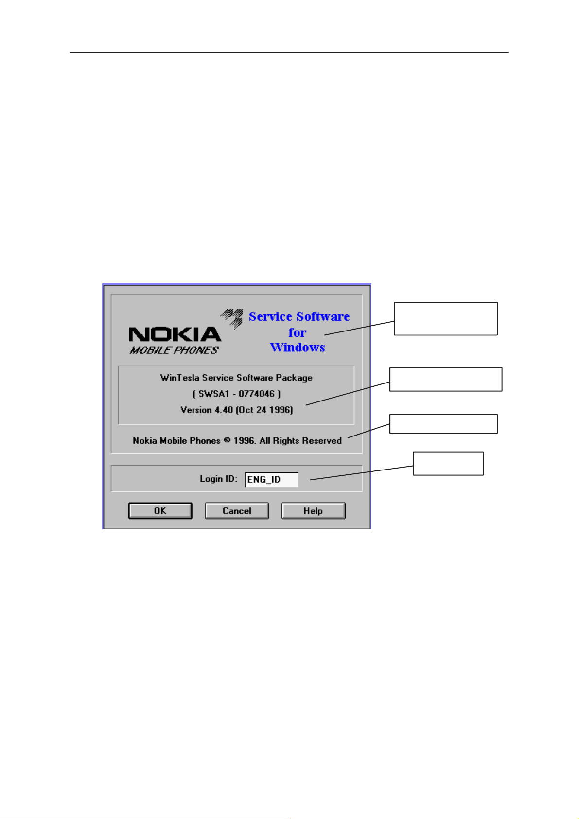
Login Dialog
When the Service Software application is invoked, by checking on the
Service Software icon, the Login dialog box will be displayed on the screen.
Nokia logo and
application name
Nokia logo and application name bitmap (–)
Displays Nokia logo and name of the application.
Application version static text (–)
Contains the name and version of the application.
Copyright notice static text (–)
Copyright is informed as: “Nokia Mobile Phones (c) 1996. All
Rights Reserved”.
Application version
Copyright version
Login box
Page 6– 8
Login Box edit box (–)
The user Login ID edit box, where the user enters his faultlog
user name. (See Faultlog User Guide)
OK button (default key)
The user name is stored in memory and the dialog box is
closed. When the dialog box is closed, the application starts.
Original, 02/99
Page 9
PAMS
RAE-2
Technical Documentation
Cancel button (ESC)
The Dialog box is closed and application is started, but the
Faultlog feature is disabled.
Help button (F1)
Activates the Windows Help application and displays context
sensitive Help.
Service SW and Tuning Instructions
Main Window
When Wintesla opens the basic screen, product specific DLL’s must be
activated using mouse to select Product –> Open
– If you want to control the CMT side, select RAE–2
– If you want to control the PDA side, select RAE2PD
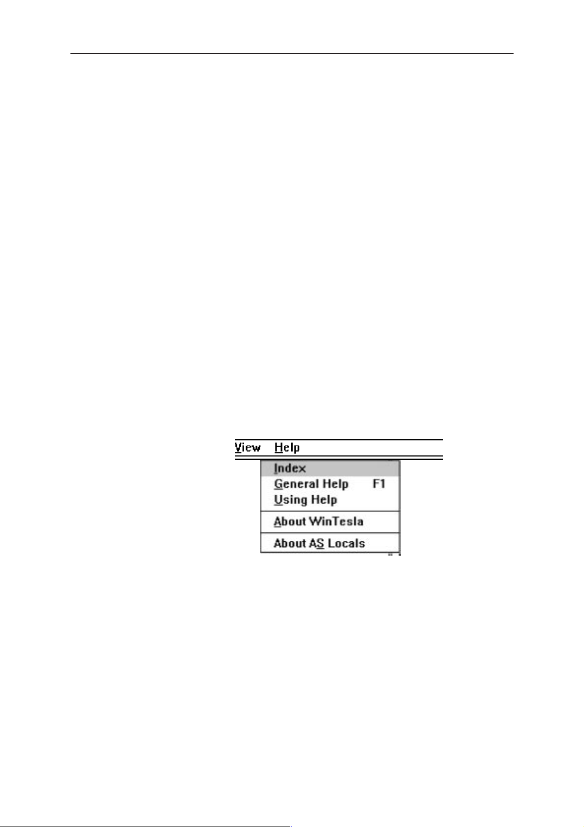
Using Help
When DLL’s are active , menu bar contains several items, including help
texts, as shown in the picture below.
Instructions for service software use can be found in the help texts. Step
by step instructions for complex operations like SW upgrades and tunings
can be found in the end of this chapter.
Original, 02/99
Page 6– 9
Page 10

RAE-2
PAMS
Service SW and Tuning Instructions
SW Update Concepts
The following lists describe the equipment which can be used in the RAE–2
software update. Nokia RAE–2 contains two main processors, one for the
PDA (Personal Digital Assistant) and one for the CMT (Cellular Mobile
T elephone). Both of these main processors have their own SW package, and
to ensure proper functionality between softwares both the CMT and the PDA
SW upgrade must be done.
Service points can perform the PDA SW upgrade only by using WinT esla RS
method. the PDA SW upgrade using multimedia card is limited only to
services with PKD1–CS or PKD–1NS SW protection key.
NOTE! All power supplies are designed to be used in Finland or in countries
with the same voltage (230 AC) and the same AC plug. More information
about power supplies with different voltages and plugs will be available later
Technical Documentation
Page 6– 10
Original, 02/99
Page 11

PAMS
RAE-2
Technical Documentation
Service SW and Tuning Instructions
Equipment for Nokia RAE-2 the PDA Flash programming
Wintesla RS
6.
9.
7.
1.
4.
8.
2. and 3.
5.
List of required equipment:
Item: Service accessory: Product code:
1 PC environment
486 processor or newer
WIN3.11/Win 95 (NT is not supported ) OS
2 Wintesla service SW 0774046
3 RAE–2N* Wintesla DLL package 0774126
4 PKD–1 SW protection key 0750018
5 DLR–2 cable or DAU–9C cable 0730138*
6 PKD–4F the PDA Flash programming dongle
0750124
7 BBS–5 Service battery 0770117
8 FLA–7 Flash Loading Adapter 0770119
9 ACL–3E power supply (FLA–7’s power supply) 0680015
*) Product code for DAU–9C. DAU–9C can control both the PDA and the
CMT, DLR–2 can control only the PDA.
Original, 02/99
Page 6– 11
Page 12

RAE-2
PAMS
Service SW and Tuning Instructions
Multimedia card
This setup can be used only if you have a PKD–1CS or PKD–1NS SW
protection key.
1.
3.
1.
Technical Documentation
2.
4.
3.
2.
Equipment list
(All product codes on the list include only one piece of equipment)
Item: Service accessory: Product code:
1 Eight PKD–4F the PDA Flash programming dongle’s 0750124
2 Eight BBS–5 Service batteries 0770117
3 Eight Flash Multimedia cards 4340513
4 One power junction unit JBP–8 0770141
** One lab. power supply
(Output curr. min. 3A, output voltage 4.1 V)
See details how to create Multimedia cards with the PDA SW upgrade
capability in SW update instructions.
Page 6– 12
Original, 02/99
Page 13

PAMS
RAE-2
Technical Documentation
Service SW and Tuning Instructions
Equipment for RAE–2N the CMT SW Upgrade
Complete Equipment for RAE–2N* the CMT SW Upgrade
NOTE!
If you already have DCT3 SW upgrade equipment and you want to
change it to be capable to perform RAE–2N the CMT SW upgrade The
you already have most of the equipment on your desk.
The complete equipment list and the list of equipment which is needed to
change DCT3 SW upgrade equipment to perform RAE–2N the CMT SW
upgrade are illustrated in next two figures.
6.
4.
15.
16.
1.
7.
9.
2. and 3.
10.
8.
5.
10.
12.
11.
13.
Complete equipment list
Item: Service accessory: Product code:
14.
1 PC environment
Original, 02/99
486 processor or newer
Page 6– 13
Page 14

RAE-2
PAMS
Service SW and Tuning Instructions
WIN3.11/Win 95 (NT is not supported ) OS
2 Wintesla service SW 0774046
3 RAE–2N* Wintesla DLL package 0774126
4 PKD–1 SW protection key 0750018
5 AXS–5 cable 0730091
6 SCH–8 cable 0730137
7 Service battery BBS–5 0770117
8 FLA–7 Flash loading adapter 0770119
9 DC power cable SCF–7 0730141
10 Two AXS–4 cables 0730090
NOTE! One AXS–4 cable included to Flash prommer (FPS–4) sales
package
11 Modular cable XCM–1 4626131
12 Flash security box TDF–4 0770106
Flash prommer FPS–4 sales package 0085095
The following items are included in FPS–4 sales package:
13 FPS–4 Flash prommer
14 Centronics cable 0730029
15 ACL–3E power supply 0680015
Technical Documentation
NOTE! FPS–Item 4 Must be ordered with memory extension modules:
1*SRAM type SF6 0200742
4*FLASH type SF7 0200743
16 ACH–6E power supply (TDF–4’s power supply) 0675084
Page 6– 14
Original, 02/99
Page 15

PAMS
RAE-2
Technical Documentation
Service SW and Tuning Instructions
Upgrade Equipment for RAE–2N* the CMT SW Upgrade
Here is the equipment list in case you already have Nokia 61XX/51XX
SW update capability.
6.
3.
5.
1.
4.
2.
Item: Service accessory: Product code:
1 SCH–8 cable 0730137
2 Modular cable XCM–1 4626131
3 Service battery BBS–5 0770117
4 FLA–7 Flash loading adapter 0770119
5 DC power cable SCF–7 0730141
6 ACL–3E power supply 0680015
RAE–2N* Wintesla DLL package 0774126
NOTE ! One ACL–3E is included to Standard (FPS–4) sales package. If
FPS–4 has been delivered with other kind power supply then ACL–3E is
needed).
Original, 02/99
Page 6– 15
Page 16

RAE-2
PAMS
Service SW and Tuning Instructions
Software update Instructions
Previous pages introduced all possible configurations that can be used in
RAE–2N* software upgrade. The following chapters contain detailed
step–by–step instructions how to perform this upgrade.
In case that equipment is not working properly:
– Check that connections are made according to insructions.
– Switch the power off from the boxes and PC and restart the whole
system.
– Clean the contact surfaces.
PDA Software Upgrade
Technical Documentation
Wintesla RS
Currently the PDA Software upgrade with Wintesla (running on Win95) lasts
approximately 8 min 30 sec. If Wintesla is running on Windows 3.1 1 upgrade
time approximately double (18 minutes).
NOTE! Remember to backup user data before SW upgrade. All user data
must be removed from the device after SW upgrade. After that user data
backups can be restored to the device.
Steps to perform upgrade:
1. Insert service battery BBS–5. Remember to check that the
2. Connect PKD–4F to service battery.
3. Connect DLR–2 (or DAU–9C) cable to PC’s serial (COM) port.
4. Connect other end of DLR–2 (or DAU–9C) to Nokia 9110
5. Start Wintesla software.
6. Select ’Open’ from Wintesla command menu.
switch on the battery is turned to ’Test’ position (Check the
label under the battery for position information).
bottom connector.
Page 6– 16
7. Select RAE2PD from the list.
8. Press ”OK”.
9. Update settings:
9..a Speed: 115200 (If Wintesla is running in WIN3.11 then
use: 57600).
9..b Port: Com1 (or 2 depending of your setup).
9..c Choose RS protocol.
Original, 02/99
Page 17

PAMS
RAE-2
Technical Documentation
10. Press ”OK”.
11. Insert Service battery’s power cable to FLA–7.
12. Once Wintesla informs ”the PDA responding in BIOS mode”
press ok. Otherwise press ”cancel” and start again from step 9.
13. Select memory –> SW update.
14. Select wanted image (*.hdr).
15. Press ok.
16. Once programming is done service SW will prompt ’ SW
utpdate successful’. Cables can now be disconnected.
17. Now the PDA software is updated. Format the file system by
pressing SHIFT–TAB–F and connect BLN–3 battery at the
same time. This will remove all user data from the device.
NOTE: Make sure that backup file you have created is stored
in a secure location before formatting file system.
Service SW and Tuning Instructions
Multimedia card
This procedure is possible only with PKD–1CS or PKD–1NS SW protection
key . For security reasons this procedure is not authorized with other PKD–1
SW protection keys.
Creating Flash programming Multimedia card
Note! You need to have PC which has Wintesla version 3.0 or newer. See
chapter 3.3 for information about installation. Y ou also need to have PKD–1
CS/NS SW protection key connected to your PC.
1. Insert empty Flash Multimedia card to RAE–2N* Multimedia
card slot
2. Insert service battery. Remember to check that Testmode
switch is turned to Testmode position (Check the label under
the battery for position information).
3. Connect DLR–2 (or DAU–9C) cable to PC’s serial (COM) port.
4. Connect other end of DLR–2 (or DAU–9C) to RAE–2N* bottom
connector.
5. Start Wintesla software from Windows desktop.
Original, 02/99
6. Select Product –> Open from Wintesla command menu.
7. Select RAE2PD from the list.
8. Press ok.
9. Update settings:
9..a Speed: 115200 (If Wintesla is running in WIN3.11 then
use: 57600).
Page 6– 17
Page 18

RAE-2
PAMS
Service SW and Tuning Instructions
9..b Port: Com1 (or 2 depending of your setup).
9..c Use RS protocol.
10. Press ok.
11. Insert Service battery’s power cable to FLA–7.
12. Once Wintesla informs ”the PDA responding in BIOS mode”
press ok. Otherwise press ”cancel” and start again from step 9.
13. Select memory –> Write Memory Card from menus.
14. Choose correct Multimedia card image file and press OK.
15. Select Memory–>Update Memory Card NMP ID
16. Disconnect Multimedia card.
the PDA SW Update with Multimedia card
Technical Documentation
NOTE! Remember to backup user data before SW upgrade. All user data
must be removed from the device after SW upgrade. After that user data can
be restored to the device.
1. Insert Multimedia card to RAE–2N* Multimedia card slot.
2. Insert service battery BBS–5.
NOTE! Check that the switch on BBS–5 is turned to ’Normal’ position (Check
the label under the battery for position information)
3. Connect PKD–4F dongle to BBS–5 Service Battery.
4. Connect BBS–5 Service Battery power cable to Power
Junction Unit JBP–8 or to flash loading adapter FLA–7.
5. Programming starts automatically and will last approximately 2
minutes .
6. Once programming is done remove all user generated data
from the device by pressing SHIFT–TAB–F.
NOTE: Make sure that backup file you have created is stored
in a secure location before formatting file system.
Page 6– 18
Original, 02/99
Page 19

PAMS
RAE-2
Technical Documentation
the CMT Software Upgrade
General
the CMT software upgrade is currently possible only by using software
upgrade equipment described earlier.
Equipment Setup instructions
1. Once TDF–4 box is first time used it has to be activated
according to instructions which come inside the TDF–4
package.
2. Connect boxes, cables and PC according to connection
drawing (Appendix).
Service SW and Tuning Instructions
3. Install FPS4 Prommer SW (release 2.00 or newer)
Installation diskettes (Product code 8400041) come with
FPS–4S (Sales pack)
4. Run setup (type ”setup .”).
5. Answer setup program’s questions according to your
environment.
Setting up the PC
1. Install WinTesla (version 5.31 or newer, rather at least 5.34)
Floppy disks can be ordered with product code 0774046
2. Install dongle drivers (combined Win3.1x, 95 and NT)
http://casw–www.ca.nmp.nokia.com/swline/WinTesla/wt_dngl.h
tm
3. Install the CMT & the PDA DLL’s
Order 3.5” floppy disks using product code 0774126
Programming with Wintesla interface
When the system has been set up, SW upgrade can be preformed according
to following instructions.
Original, 02/99
1. Insert BBS–5 service battery. Remember to check that switch
on the battery is in ’Test’ position (Check the label under the
battery for position information).
2. Connect SCH–8 cable to FLA–7’s ”service cable” connector.
3. Connect power cable to FLA–7’s ”service battery
communicator” connector.
Page 6– 19
Page 20

RAE-2
PAMS
Service SW and Tuning Instructions
4. Connect SCH–8 cable to N9110’s bottom connector by using
bottom connector adapter.
5. Turn the CMT on by pressing power button.
6. Start Wintesla software.
7. Select Product –> Open –> RAE2.
8. Press F5 to initialize phone in local mode.
9. Select Software –> Flash Phone.
10. New dialog opens.
11. Select software image: Press ”Load image” button.
12. Select PPM image: Press ”Load PPM” button.
13. Check from the PDA display that Relink –connection is ready.
14. Press ”Flash” button.
15. Once program is prompting for restoring user data choose
either YES or NO.
Technical Documentation
NOTE! If you select YES user data (the CMT profile settings, Voice mail
number, Welcome graphics, dealer&operator setting and divert number
settings) will be saved to file.
16. Programming starts.
17. When service SW asks you to check that phone is on, switch
the phone on if necessary.
18. Flash authority ID, Factory setup values and user settings
(optional) are updated.
19. After flash programming completed message you can close the
flash dialog.
20. Disconnect Nokia 9110.
Troubleshooting for the CMT SW upgrade
If something went wrong during flashing:
1. Switch the phone on and scan the CMT with CTRL–R.
2. Flash again without restoring user settings.
3. Restore user settings that were read during first attempt by
using ’Dealer–>SCM&User settings’ Select file with ”Select
File” button and then press ’Save’ button.
Page 6– 20
If you have a dead the CMT:
1. Do not try to switch phone on.
2. Use Product–>Open–>RAE–2. Wintesla will prompt you
’Found COMBOX without phone, open flash only menu?’
Answer Yes and then use Software –>Flash Phone.
Original, 02/99
Page 21

PAMS
RAE-2
Technical Documentation
3. This time user settings can not be read. After flashing ’Restore
Default User Settings’ dialog is opened and you can select
which default settings you want to download to the CMT.
4. Later you can use ’Dealer–>SCM&User settings’ to return your
the CMT settings if you have earlier saved them to a file. the
CMT settings can be saved by using ’Dealer–>SCM&User
settings’ and ’Read Phone’ button.
Service SW and Tuning Instructions
Original, 02/99
Page 6– 21
Page 22

RAE-2
PAMS
Service SW and Tuning Instructions
RF Tuning Instructions
General
All tuning operations of the RAE–2 are carried out using the service
software. The service software turns the phone into the locals mode, in
which the phone can be outwardly controlled via the MBUS interface. This
MBUS interface can be found from the bottom of the phone.
Tuning is based on the software communicating with the D/A and A/D
converters of the phone. In some instances the phone processor will also
calculate the required correction parameter.
The tuning values of the phone reside on the EEPROM. The contents of the
EEPROM can be read by the service software and saved as a file. This is
advisable when there is need to retain that information, e.g. in view of
replacement of the circuit. The program also enables writing the default
parameters on the EEPROM, in which case all tuning steps should be carried
out.
Technical Documentation
During tuning, proceed as follows:
– Take care not to damage sensitive measuring instruments with
excessive RF power.
– Carry out all tuning steps in the shortest possible time to avoid
excessive heating of RF units.
– Perform all tuning steps in the order presented.
– Never try to mask a fault by tuning it out!
Required Equipment
– PC/AT computer with service software; see separate section for
instructions on installation and use.
– Service accessories; see equipment setup lists.
– Multimeter or DVM.
– GSM radio telephone test station or separate measuring equipment as
follows:
– RF generator
– pulse power meter
– spectrum analyzer
– attenuator and branching unit
Equipment Setup
Caution: Make sure that you have switched off the PC and the printer
Page 6– 22
before making connections !
Original, 02/99
Page 23

PAMS
RAE-2
Technical Documentation
Caution: Do not connect the PKD–1 key to the serial port. You may
Attach the protection key PKD–1 to parallel port one (25–pin female
D–connector) of the PC. When connecting the PKD–1 to the parallel port be
sure that you insert the PC end of the PKD–1 to the PC (male side). If you
use a printer on parallel port one, place the PKD–1 between the PC and your
printer cable.
Next see the following lists for correct equipment. Different equipment is
needed when tuning phone without removing covers or when tuning phone
with covers removed.
Service SW and Tuning Instructions
damage your PKD–1 !
Original, 02/99
Page 6– 23
Page 24

RAE-2
PAMS
Service SW and Tuning Instructions
Technical Documentation
Equipment Setup for RF Tuning RAE–2 Phone Without Removing
Covers
1.
1.
2.
2.
5.
5.
4.
4.
3.
3.
7. and 8.
7. and 8.
6.
6.
Item: Service accessory: Product code:
1 Service battery BBS–5 0770117
2 Calibration Unit JBE–1 (* 0770118
3 Service Car Kit HCR–2 0770146
4 Modular T–adapter 4626134
5 Software protection key PKD–1 0750018
6 MBUS cable DAU–9S 0730108
7 Wintesla Service SW 0774060
8 WinTesla product specific DLL’s for RAE–2N* 0774126
** Laboratory power supply 3A/12V (adjustable)
Page 6– 24
*) Never use FLA–7 for tunings.
Original, 02/99
Page 25

PAMS
RAE-2
Technical Documentation
Service SW and Tuning Instructions
Tuning RF with covers Off –using Module Jig MJS–4
2.
3.
5. and 6.
4.
1.
Item: Service accessory: Product code:
1 Module Jig MJS–4 0770116
2 MBUS cable DAU–9S 0730108
3 Modular T–adapter 4626134
4 Software protection key PKD–1 0750018
5 Wintesla Service SW 0774046
6 WinTesla product specific DLL’s for RAE–2N* 0774126
** Laboratory power supply 3A/12V (adjustable)
Original, 02/99
Page 6– 25
Page 26

RAE-2
PAMS
Service SW and Tuning Instructions
Tuning EM without removing covers
NOTE: EM values can not be tuned in module jig MJS–4
1.
2.
Technical Documentation
3.
5.
6. and 7.
4.
Item: Service accessory: Product code:
1 Service battery BBS–5 0770117
2 Calibration Unit JBE–1 0770118
3 Software protection key PKD–1 0750018
4 MBUS cable DAU–9C 0730138
5 DC cable SCB–3 0730114
6 Wintesla Service SW 0774046
7 WinTesla product specific DLL’s for RAE–2N* 0774126
** Laboratory power supply 3A/12V (adjustable)
Page 6– 26
Original, 02/99
Page 27

PAMS
RAE-2
Technical Documentation
Tuning Steps
RX Calibration (AGC + AFC)
Reference values for the received signal strength meter are program tuned.
RSSI reference signal level programming:
– Select
– Connect RF generator to service jig antenna connector at 947.067710
MHz.
– Adjust signal generator level to –55 dBm + cable attenuation.
– Press
– Adjust signal generator level to –80 dBm + cable attenuation.
Tuning –> RX Calibration
OK
button
Service SW and Tuning Instructions
– Press
Service software reports:
A Table of AFC Parameters:
A Table for AGC Calibration:
– Press
OK
button.
AFC INIT Value
AFC Slope
PSW Slope
AGC in 3 db steps 0...57 dB
DAC and voltage reading for each gain value
SAVE
button
I/Q Modulator Amplitude Balance and Phase Shift Tuning
The purpose of this tuning operation is to adjust the I/Q modulator d.c.
offsets and the I/Q modulator amplitude balance and phase shift.
I/Q modulator d.c. offsets, amplitude balance and phase shift tuning:
– Select
Tuning –> TX I/Q...
– Select I/Q tuning values from PC’s memory, phone’s EEPROM or
factory default values.
– Connect spectrum analyzer (with attenuator if needed) to service jig
antenna connector.
– Check that TX power level is level 10, channel is 60 and TX data type
is 1.
– Adjust spectrum analyzer centre frequency to 902 MHz, Span 200
kHz, Res BW 10 kHz, Video BW 1 kHz and Sweep time 0.5 s.
Original, 02/99
Page 6– 27
Page 28

RAE-2
PAMS
Service SW and Tuning Instructions
–67.71 kHz +67.71 kHz
D.C. offset
tunings:
Set this value
to minimum
CHF
> 30 dB
Technical Documentation
> 35 dB
Amplitude &
phase difference:
Set this value
to minimum
– Select the ”TX I d.c. offset” option.
– Adjust the level of centre frequency (CHF signal) to minimum by
varying D/A converter value with
<–
and –> buttons.
– The amplitude difference between CHF–67.7 kHz and CHF should be
>30 dB.
– Select option ”TX Q d.c. offset”.
– Adjust the level of signal CHF to minimum by varying D/A converter
value with <– and
–>
keys.
– Use the ”Amplitude Difference” option.
– Adjust the level of signal CHF+67.7 kHz (902.06777 MHz) to minimum
by varying D/A converter value with <– and –> keys.
– The amplitude difference between CHF+67.7 kHz and CHF–67 kHz
should be >35 dB.
– Select the ”Phase Difference” option.
– Adjust the level of signal CHF+67.7 kHz to minimum by varying D/A
converter value with <– and –> keys.
– When values are correct press
SAVE
button.
Page 6– 28
Original, 02/99
Page 29

PAMS
RAE-2
Technical Documentation
Tuning of Transmitter Power Levels
This adjustment loads the power levels of the phone transmitter into the
EEPROM. When doing this, a pulse power meter or spectrum analyzer must
be used.
Power levels programming:
– Select
– Select I/Q tuning values from PC’s memory, phone’s EEPROM or
factory default values.
– Set power supply voltage 3.7 V to module jig (MJS–4). When tuning
without removing covers, supply 7.0V to JBE–1.
– Connect pulse power meter or spectrum analyzer to antenna
connector.
Tuning –> TX Power...
Service SW and Tuning Instructions
– Check that channel is 60.
– Adjust the power level (levels 5, 15 and 19) by clicking the + and –
buttons, and change levels with ↑
Power level
5 32.7
15 13.0
19 7.0
Base –25.0
Note: If the base calculation feature is enabled, then the base level is
calculated automatically.
– Press
– Once all TX levels are correct, press
Calculate
Tuning P
(CH 60)
button to calculate all other levels.
OUT
and ↓ keys.
/dBm
SAVE
button.
Original, 02/99
Page 6– 29
Page 30

RAE-2
PAMS
Service SW and Tuning Instructions
Energy Management Calibration
NOTE: This can not be done in module jig MJS–4. EM calibration is
possible only when phone is completely assembled.
– Connect DAU–9C cable and BBS–5 battery to RAE–2N phone
– Connect BBS–5 to the calibration unit JBE–1 and DC cable SCB–3
between phone and calibration unit.
– Connect JBE–1 to laboratory power supply which is adjusted to 7.0V
– Start Wintesla service SW
– Select Tuning –> Energy Management Calibration
– Run calibrations separately or all at once as described in the following
list. Connect 10.5V to the calibration unit JBE–1 as prompted by service
SW.
– Select calibrations:
Technical Documentation
Battery & charger default values
– Select 1.Run Battery & charger default values
checkbox
Battery voltage
– Select 2.Battery voltage checkbox
Charger voltage
– Select 3.Charger voltage checkbox
Battery size
– Select 4.Battery size checkbox
Battery temperature
– Select 5.Battery temperature checkbox
Charge current
Page 6– 30
– Select 6.Charge current
– Select Save without confirmation, if you don’t want
confirm all the selected calibration values before saving
– Run calibrations by pressing Run button
– Set supply voltage back to 7.0 V
1
[]
Original, 02/99
 Loading...