

Page 1

PAMS Technical Documentation
RAE–2 Series PDA Phone
Chapter 09
Mechanical Parts and
Disassembly
Original 02/99 Copyright 1999 Nokia Mobile Phones. All rights reserved.
Page 2
RAE–2
PAMS
Mechanical Parts
Amendment
Number
Technical Documentation
AMENDMENT RECORD SHEET
Date Inserted By Comments
02/99 Original
Page – 2
Original 02/99
Page 3

PAMS
RAE–2
Technical Documentation
CONTENTS
Exploded Diagram – 4. . . . . . . . . . . . . . . . . . . . . . . . . . . . . . . . . . . . . .
List of Mechanic Parts – 5. . . . . . . . . . . . . . . . . . . . . . . . . . . . . . . . .
LCD / UI Module Disassembly – 6. . . . . . . . . . . . . . . . . . . . . . . . . . .
System Module Disassembly – 8. . . . . . . . . . . . . . . . . . . . . . . . . . . . .
Mechanical Parts
Page No
Original 02/99
Page – 3
Page 4

RAE–2
PAMS
Mechanical Parts
RAE–2 Exploded diagram below
Technical Documentation
1
2 3
5
4
6
14
26
7
8
10
12
16
17
24
18
20
22
19
21
9
11
13
15
23
Page – 4
30
34
28
32
33
25
27
29
31
Original 02/99
Page 5

PAMS
RAE–2
Technical Documentation
List of Mechanic Parts
Item Code Description Specifications / Ratings
1 9456203 Front cover with lens
2 6190033 Screw M1,6x5 6 pcs 6x M1,6X5
3 9790326 Phone keypad
4 0201097 Phone UI PCB
5 4850063 Phone LCD
6 4850801 PDA Display ELbacklight
7 9855044 Hingle flex
8 4850049 PDA LCD
9 9780234 Coaxial cable
10 9460251 Flex cover
11 9460248 Hinge end
Mechanical Parts
12A 9460249 Latch
12B 6402165 Spring
13 0660183 Antenna
14 9790330 Function keypad left
15 9790320 Function keypad right
16 9451258 IR window
17 9456209 Screen frame
18 0201096 PDA PCB
19 9367026 Keypad frame
20 9547007 Chassis
21 9790313 QWERTY keypad Note: English language keypad
22 ** CMT PCB Not available as spare part
23 5140119 HF speaker
24 5469091 System connector
25 9467029 Audio holder
26 9510421 Metal gasket
27 5140067 Earpiece
28 5140133 Microphone
29 9451261 Audio cover
30 9456156 Back cover
31 6190013 Screws 6 x M1,6x7
32 9451257 Card cover
33 9510425 Card shield
34 9470052 Plug 4 pcs
Original 02/99
Page – 5
Page 6

RAE–2
PAMS
Mechanical Parts
LCD / UI Module Disassembly
1. Remove battery.
2. Remove cover label (A) and screw (B).
3. Gently lift off front cover starting from both sides in the bottom
end of the phone or by pulling the top end of front cover.
4. Remove phone keymat.
5. Remove 5 screws (C) and 2 washers (D).
6. Disconnect flex connectors by releasing connector clips. Connectors will be opened by lifting the clip up.
7. Unplug the coaxial cable.
8. Unclip UI PCB from PDA LCD by lifting up 3 metal clips (E).
9. Remove phone LCD. Do not try to remove phone LCD without
opening the metal clip. Elastomer might be damaged.
Technical Documentation
10. Remove UI PCB, display EL backlight, PDA LCD and function
keypads.
Note 1: Latch and spring, spring flies away quite easily.
Note 2: PDA LCD is connected to screen frame with tapes. Al-
ways use new tapes when re–assembling.
11. Remove antenna. Use a knife or a small screwdriver to lift
plastic clip which blocks the antenna.
12. Re–assemble in reverse order and observe the following
points:
–Check that coaxial cable goes behind guide pin and does not
get trapped under front cover.
See further details in figure1
–Note that torque of the screws must be 10 Ncm.
–Assembly flex cover so that mat side is inside the phone.
The correct way to assembly coaxial cable is described in the next page.
Page – 6
Original 02/99
Page 7

PAMS
RAE–2
Technical Documentation
Mechanical Parts
Figure 1.
Figure1. Correct way to assemble the coaxial cable in the lid part.
Original 02/99
Page – 7
Page 8

RAE–2
PAMS
Mechanical Parts
System Module Disassembly
1. Remove battery.
2. Remove four plugs (34) and six screws (31).
3. Remove audio cover, audio holder and back cover, be careful
not to touch sensitive parts of earpiece.
4. Unplug the coaxial cable.
5. Remove CMT PCB, system connector and IR window. CMT
PCB might be very tightly connected, use necessary force to
remove it.
6. Open chassis. Disconnect flex connector by releasing connector clip. Connector will be opened by lifting the clip up.
7. Remove PDA PCB.
Technical Documentation
8. Remove chassis; at first from the lower hinge, easiest position
is to put the hinge almost 180° angle, and remove the chassis
then. Be careful not to damage coaxial cable.
9. Remove QWERTY keypad and keypad frame. Do not touch
carbon connections surfaces on QWERTY keypad.
10. Re–assemble in reverse order and observe following points:
–Re–assemble chassis first to the upper hinge and check
coaxial cable.
–Re–assemble PDA PCB and connect flex connector when
chassis is open.
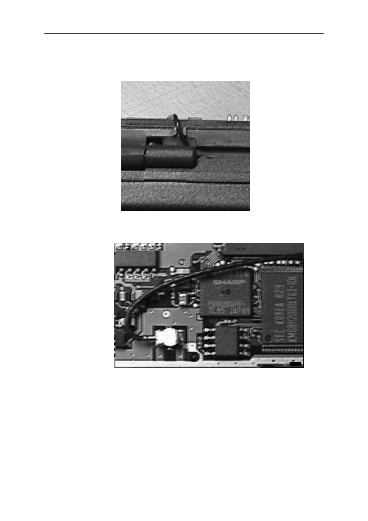
–Coaxial cable must go under the hinge flex and between two
bulbs on keypad frame. See picture. (figure 4)
–Check that coaxial cable does not get trapped.
–Check that coaxial cable goes to CMT PCB between two
bulbs. See pictures.(figure 2 and figure 3)
–Notice that torque of screws must be 15 Ncm.
11. Figures 2 to 4 : The correct way to assemble coaxial cable.
Page – 8
Original 02/99
Page 9
PAMS
RAE–2
Technical Documentation
Mechanical Parts
Figure 2.
Figure 2. Correct way to assemble coaxial cable between the guiding pins.
Figure 3.
Figure 3. Correct way to assemble coaxial cable on CMT PCB.
Original 02/99
Page – 9
Page 10

RAE–2
PAMS
Mechanical Parts
Figure 4. Correct way to assemble coaxial cable under hinge flex cover.
Technical Documentation
Page – 10
Original 02/99
 Loading...