

Page 1

PAMS Technical Documentation
RAE–2 Series PDA
Chapter 13
Accessories
Original 02/99
Copyright 1999 Nokia Mobile Phones. All rights reserved.
Page 2

RAE–2
PAMS
Accessories
Amendment
Number
Technical Documentation
AMENDMENT RECORD SHEET
Date Inserted By Comments
02/99 Original
Page 13 – 2
Original 02/99
Page 3

PAMS
RAE–2
Technical Documentation
CONTENTS
Units and Accessories 13 – 4. . . . . . . . . . . . . . . . . . . . . . . . . . . . . . . . . . .
Headset HDC-8 13 – 5. . . . . . . . . . . . . . . . . . . . . . . . . . . . . . . . . . . . . . . . .
Technical Summary 13 – 5. . . . . . . . . . . . . . . . . . . . . . . . . . . . . . . .
List of Modules 13 – 5. . . . . . . . . . . . . . . . . . . . . . . . . . . . . . . . . . . .
Desktop Charger DCH–7 13 – 6. . . . . . . . . . . . . . . . . . . . . . . . . . . . . . . .
Technical Summary 13 – 6. . . . . . . . . . . . . . . . . . . . . . . . . . . . . . . . . . .
Rear Connector View Desk Stand 13 – 7. . . . . . . . . . . . . . . . . . . .
Interconnection Diagram 13 – 8. . . . . . . . . . . . . . . . . . . . . . . . . . . .
Handset HSU–1 13 – 9. . . . . . . . . . . . . . . . . . . . . . . . . . . . . . . . . . . . . . . .
Accessories
Page No
Technical Summary 13 – 9. . . . . . . . . . . . . . . . . . . . . . . . . . . . . . . .
Use of Handset 13 – 9. . . . . . . . . . . . . . . . . . . . . . . . . . . . . . . . . . . .
Memory Card MMC DTS–4 13 – 10. . . . . . . . . . . . . . . . . . . . . . . . . . . . . .
Fast Travel Charger ACP–9 13 – 11. . . . . . . . . . . . . . . . . . . . . . . . . . . . . .
Product Codes 13 – 11. . . . . . . . . . . . . . . . . . . . . . . . . . . . . . . . . . . . .
Specification 13 – 11. . . . . . . . . . . . . . . . . . . . . . . . . . . . . . . . . . . . . . .
RS232 Adapter Cable DLR–2 (073077) 13 – 12. . . . . . . . . . . . . . . . .
Cigarette Lighter Charger LCH–9 (0675005) 13 – 13. . . . . . . . . . . . .
Original 02/99
Page 13 – 3
Page 4
RAE–2
PAMS
Accessories
Technical Documentation
Units and Accessories
All RAE–2N accessories are non–serviceable.
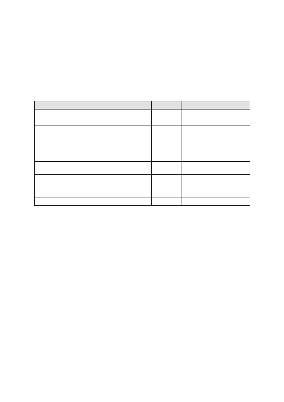
Table 1. List of Units and Accessories
Name of unit or accessory Type code Notes
Battery BLN–3 1030 mAh, Li–Ion
Performanace Travel Charger ACP–9
Headset HDC–8
Advanced Deskstop Stand DCH–7 Includes synchronization but-
ton for PC connection
RS–232 Adapter Cable DLR–2
Carrying Case CBR–4
Memory Card DTS–4 Removable memory card.
MMC
Advanced HF Car Kit CARK–99
Privacy Handset HSU–1
Mobile Charger LCH–9
Upgrade HF Car Kit CARK–102
Page 13 – 4
Original 02/99
Page 5
PAMS
RAE–2
Technical Documentation
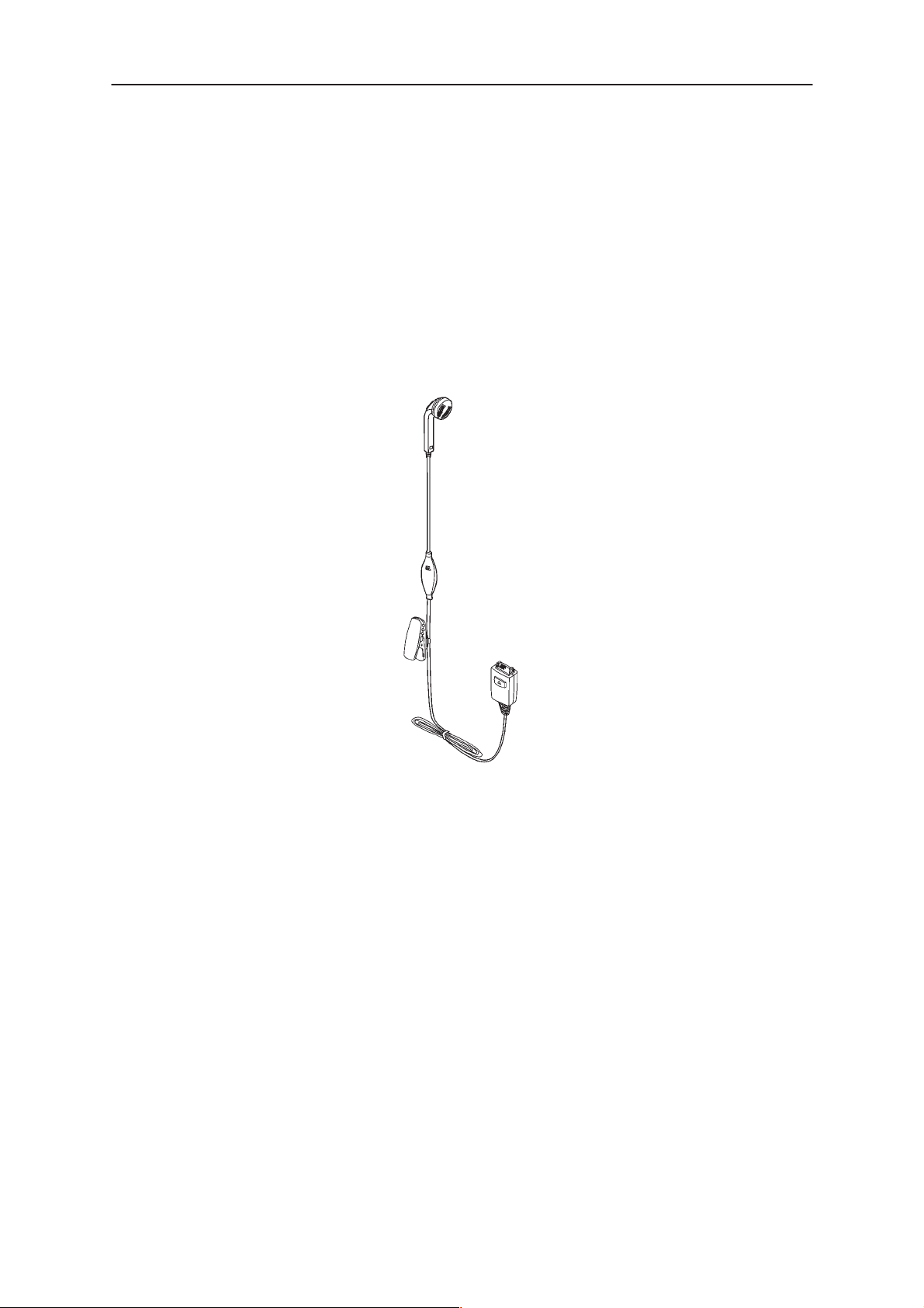
Headset HDC-8
Connect the HDC–8 to the bottom connector of phone, and it is ready to
use. The push button at microphone part can be used for answering and
ending the call.
Accessories
Technical Summary
HDC–8 headset contains a microphone, a speaker, EMI–components
and CONTROL button . Headset will be connected straight to the bottom
connector of the phone.
Headset can be used also with the car kit.
List of Modules
Headset HDC–8
Figure 1. HDC–8
Original 02/99
Page 13 – 5
Page 6

RAE–2
PAMS
Accessories
Desktop Charger DCH–7
Desktop charger DCH–7 is designed for the charging of the RAE–2 PDA
and a spare battery.
Technical Documentation
Technical Summary
The desktop charger DCH–7 is a two–slot stand designed to be placed on
a desk–top. The front slot holds and charges the phone, and the rear slot
holds and charges a spare battery.
The desk stand includes red and green LEDs to show the status of the
spare battery charging in the rear slot.
The desk stand supports charging of 4.1V and 4.2V lithium–ion batteries.
The desk stand is powered by an external ACP–9A/E/U/X performance
travel charger. When a RAE–2 is placed in the front slot it is charged at
the same rate as if the external charger was connected directly to the
phone. When a spare battery is placed in the rear slot, it is charged at a
slower rate. Charging of the spare battery is delayed until the phone has
finished charging.
The front slot provides data connection between the deskstand connected
PC and the RAE–2. The host PC is connected by Nokia data cable to the
Figure 2. DCH–7 Desk Stand
Page 13 – 6
Original 02/99
Page 7

PAMS
RAE–2
Technical Documentation
rear of the desk stand. The PC must have the Nokia ”Share” software
running for the data transfer to the PC to be successful.
Rear Connector View Desk Stand
The rear connector allows for the Nokia PC data cable to be connected to
the Spock whilst in the desk stand. The cable is connected to the rear of
the desk stand and the desk stand provides routing of the signals to the
Spock phone.
The rear connector provides for connection of the charger to the desk
stand.
Accessories
The desk stand provides a convenient push button, called a ”Share” button to initiated the phone to PC data synchronization. The data transfer
from the phone to the PC is then achieved via the phone serial data link
[Fbus]. The Nokia Data cable is required for connection of the desk stand
to the PC.
Original 02/99
Figure 3. DCH–7 Deskstand
Page 13 – 7
Page 8

RAE–2
PAMS
Accessories
Interconnection Diagram
PC
CHARGER
serial cable
Fbus to Rs232
DESKSTAND
Fbus
Front
slot
Technical Documentation
PHONE
3–wire
AC supply
SPARE BATTERY
DC–jack
Rear
slot
Figure 4. Interconnection Diagram
Page 13 – 8
Original 02/99
Page 9

PAMS
RAE–2
Technical Documentation
Handset HSU–1
The main function of the HSU–1 Audio Handset is to form an electroacoustic interface between the user and the phone environment.
Accessories
Technical Summary
The HSU–1 Audio Handset consists of handset with coil cord and of
cradle. In the handset there is earphone and microphone with corresponding amplifiers. There is also a simply interface for controlling these
functions. Electronics consist of DG–1 handset module. Mechanical dimensions are small and mechanics consists of A–cover, B– cover and coil
cord with the cradle. The HSU–1 Audio Handset has a volume potentiometer.
Use of Handset
The HSU–1 Audio Handset is designed to be a dummy handset with no
display and no keyboard. Its use is to form an electroacouistical connection between the user and DCT – environment. When not in use the
handset is on the cradle. During the use the handset is lifted from the
cradle and audio paths are opened.
HSU–1
Original 02/99
Page 13 – 9
Page 10

RAE–2
PAMS
Accessories
Memory Card MMC DTS–4
The PDA includes a synchronous serial interface that is compatible with
the Multimedia Card Bus (MMC) Protocol. The MMC is a changeable
Flash or ROM memory card with variable memory size. The MMC connector is located on the BS8 Module..
1 234567
Technical Documentation
32mm
24mm
Figure 5. DTS–4 Dimensions
1.5mm
Page 13 – 10
Original 02/99
Page 11

PAMS
RAE–2
Technical Documentation
Fast Travel Charger ACP–9
Operating within the voltage range 90 V...264 V AC (50 Hz...60 Hz), the Fast
Travel Charger is practically current independent in normal office and household use. Like the standard charger, it is compatible with all battery options
and is available for different wall sockets.
The Fast Travel Charger can also be used with basic stand and desktop
stand.
ACP–9E
ACP–9U
Accessories
ACP–9X
ACP–9A
Product Codes
Fast Travel Charger (Euro plug) 90–264 Vac ACP–9E 0675149
Fast Travel Charger (US plug) 90–264 Vac ACP–9U 0675151
Fast Travel Charger (UK plug) 90–264 Vac ACP–9X 0675150
Fast Travel Charger
Output cable PCC–1
Specification
Output connectors:
Protection:
Output voltage/current (typ):
(Australia) 90–264 Vac ACP–9A 0675152
(supplied with ACP–9):
0730076
3.5 mm DC plug, 3–pole (+, –, control)
output current limiting, max. 850 mA
output voltage limiting, max. 9.3 V (unloaded)
8.4 V / 800 mA
Original 02/99
Page 13 – 11
Page 12

RAE–2
PAMS
Accessories
RS232 Adapter Cable DLR–2 (073077)
Purpose Connects an external computer with RAE–1N
(via PAR–1) see below
Cable length 950mm 25 mm (3 wire, 3.5 mm)
D connector D9 connector female
Stereo connector Stereo plug (2.5 mm)
with 3.5 mm strain relief
Technical Documentation
Page 13 – 12
Original 02/99
Page 13

PAMS
RAE–2
Technical Documentation
Cigarette Lighter Charger LCH–9 (0675005)
Accessories
Purpose charging adapter for car environment; input voltage
9...32 V
Charger type Switching mode power supply
Operation quick charge (< 0.5–2.5 h), trickle charge
Protection input fused, output current limit
Connectors output: 3.8 mm standard DC plug;
input: D 21 / 23 mm
Weight <120 g
Cable 2 m curly cable
NOTE! The current version of LCH–2 does not indicate (led illumination) in
a correct way what is the status of the charging with Li batteries.
For quick car installation, the user can utilise the Cigarette Lighter Charger
LCH–2, Power Adapter PAR–1, and RS232 serial cable DLR–1 Mobile
Holder MBR–1 cannot be used in this context.
Original 02/99
Page 13 – 13
Page 14

RAE–2
PAMS
Accessories
Technical Documentation
This page intentionally left blank.
Page 13 – 14
Original 02/99
 Loading...