

Page 1

nokia
RAE/K-1 Repairhints
Service & Competence Center Europe
Customer Care Training Group Date 05.04.2001
CONFIDENTIAL
Introduction Version 1.0 Approved
Repairhints
1 (29)
Communicator
9000/9000i
RAE/K-1/4
© NMP 2001
Checked by:
Customer Care Training Group
Approved by:
SCCE
Page 2

nokia
RAE/K-1 Repairhints
Service & Competence Center Europe
Customer Care Training Group Date 05.04.2001
CONFIDENTIAL
Introduction Version 1.0 Approved
GENERAL
-General handling
PDA-module GP-1, SIM-Flex GEM-1 and PDA-LCD are the same for all products.
CMT-module GE-8s ( MCM1 code 0200725 ) and User Interface-module GK-2 are meant for RAE-1/I,
while GE-9s ( MCM1 code 0200865 ) and UI-module GK-2-1 are meant for RAK-1/I.
To find out a failure easier, interchange separate modules with some which are working proper,
so that you can define the fault to a single module. Check general every connector for broken
solderings, if bent or soiled.
EMC grounding tape is recommended to replace always with new one after removal.
Take care not to destroy HF-Microphone and Coax-cable when assembling the communicator,
further more it is absolutely necessary to use the right screws at their intended places!
-Component characteristics:
Some components contain important data.
Several described steps are only practicable if you are able to reflash/ realign the phone and/or rewrite
IMEI/SIMlock in certain cases. Please pay attention to separate notes.
-Realign after repair
Characteristics of replacement parts are different.
To prevent additional faults after repair (eg. low standby time, loosing network etc…) it is necessary
to retune phone values after repair.
2 (29)
© NMP 2001
Checked by:
Customer Care Training Group
Approved by:
SCCE
Page 3

nokia
RAE/K-1 Repairhints
Service & Competence Center Europe
Customer Care Training Group Date 05.04.2001
CONFIDENTIAL
Introduction Version 1.0 Approved
INTRODUCTION
IMPORTANT:
This document is intended for use by authorized NOKIA service centers only.
The purpose of this document is to provide some further service information for NOKIA Communicator 9000/I.
It contains a lot of collected tips and hints to find failures and repair solutions easily.
It also will give support to the inexperienced technicians.
Saving process time and improving the repair quality is the aim of using this document.
We have built it up based on fault symptoms (listed in "Contents") followed by detailed description for further
analysis.
It is to be used additionally to the service manual and other service information like Service Bulletins, for that
reason it doesn't contain any circuit descriptions or schematics.
3 (29)
All measurements are made using following equipment:
Nokia repair SW : PCLocals V 1.9 for GSM / PC Locals V 0.7 for PCN
Nokia Module Jig : MJS-1
Digital multimeter : Fluke 73
Oscilloscope : Hitachi V-1565; Fluke PM 3380A/B
Spectrum Analyser : Advantest R3131 with an analogue probe
RF-Generator / : Rohde & Schwarz CMU 200
GSM Tester
Temperature chamber : Vötsch VT 4002
While every endeavour has been made to ensure the accuracy of this document, some errors may exist. If the
reader finds any errors, NOKIA should be notified in writing, using following procedure:
Please state:
Title of the Document + Issue Number/Date of publication.
Page(s) and/or Figure(s) in error.
Please send to: Nokia GmbH
Service & Competence Center Europe
Meesmannstr.103
D-44807 Bochum / Germany
Email: training.sace@nokia.com
© NMP 2001
Checked by:
Customer Care Training Group
Approved by:
SCCE
Page 4
nokia
RAE/K-1 Repairhints
Service & Competence Center Europe
Customer Care Training Group Date 05.04.2001
CONFIDENTIAL
Introduction Version 1.0 Approved
Contents
HW-CHANGES 5
UI-PROBLEMS 6
SIMCARD FAULTS 7
NOT CHARGING 10
SELFTEST FAILED 12
CMT DOES NOT SWITCH ON 13
SWITCHES OFF INTERMITTENT 15
PDA MODULE FAULTY 16
POOR OR NO SERVICE (RAE-1) 17
LOW OR NO TX POWER (RAE-1) 19
POOR OR NO SERVICE (RAK-1) 21
LOW OR NO TX POWER (RAK-1) 23
TX I/Q PROBLEMS 25
SIGNAL CHARTS 26
CHANGE HISTORY 29
4 (29)
© NMP 2001
Checked by:
Customer Care Training Group
Approved by:
SCCE
Page 5

nokia
RAE/K-1 Repairhints
Service & Competence Center Europe
Customer Care Training Group Date 05.04.2001
CONFIDENTIAL
Introduction Version 1.0 Approved
HARDWARE CHANGES RAE-1 / RAK-1
SB 010 / RAE-1
STRANGE CHARACTERS ON THE DISPLAY
In some communicators the phone display (LCD) becomes scrambled if the user has pressed e.g. 2-5-8-0 keys of
the phone’s keypad very quickly. Typically there will be additional, missing or odd pixels at the top of the field
strength or battery level bars. To prevent these strange characters to appear at the display, the value of C346 has
been changed from 100 pF to 47 pF (On GE8 module).
SB 015 / RAE-1 SB 004 / RAK-1
NEW REED RELAY S170
This new relay is more reliable and sensitive than the old one. Change if display message “PLEASE CLOSE COVER”
appears while cover is fully closed.
This modified relay was used in production from IMEI number 490169/10/041518/0.
SB 017
NEW HARDWARE VERSIONS 5.0 AND 5.1
To improve phone’s LCD functionality and for better PDA-performance, several changes have been done,
for details see Service Bulletin 017
5 (29)
© NMP 2001
Checked by:
Customer Care Training Group
Approved by:
SCCE
Page 6

nokia
CONFIDENTIAL
RAE/K-1 Repairhints
Service & Competence Center Europe
Introduction Version 1.0 Approved
Customer Care Training Group Date 05.04.2001
USER INTERFACE PROBLEMS
Check all connectors and flexfoils for their condition –if bent, dirty or poor soldered.
Display failures
CMT: Too low or too strong Display contrast or missing segments:
Check for poor soldering and/or mechanical condition of flexfoil
Check if segments missing after fast pressing keypad (eg. keys 2-5-8-0)
If this is the case – change C346 from 100pf to 47 pf
see also Service Bulletin 010 for GE8 Modul
unstable LCD backlight – change PSL N230
PDA: Bad or flickering LCD – Display driver defect – change Display
LCD Contrast problems – check/change R93, R97
Audio failures
Always check GEM-1 SIMFLEX connections / - connectors X001 (UI) and X212 (CMT)
Bad Audio Quality incoming (Xmic) – check Earphone B001 if dirty / change if necessary.
Bad Audio Quality outgoing (MicX) – check Mic B002 for dirt / change if necessary.
Ringing tone problems – check Buzzer B003 if dirty or bend / change if necessary.
Keypad failures
If there are problems with any keypad and/or functionkeys –
Metal key domes are possibly mechanically defect –
disconnect CMT LCD and change GK2 / GK2-1 PCB.
SIM failures
Check mechanical condition of GEM-1 SIMFLEX.
Check connections / -connectors of SIMFLEX.
Check pads of SIMCARD reader X002 if bent.
Change GEM-1 SIMFLEX if necessary.
General start problems
Internal failure respectively Screensaver Error GEOS.ini.
Try to format and make SW – update after formatting.
This can be done with service-software
or by pressing Shift + Esc + F and installing the battery to boot the communicator.
Keep the keys pressed until you get a screen to confirm the formatting.
Note that formatting will remove all user-generated data. You should save user`s data before proceed !
6 (29)
© NMP 2001
Checked by:
Customer Care Training Group
Approved by:
SCCE
Page 7
nokia
CONFIDENTIAL
RAE/K-1 Repairhints
Service & Competence Center Europe
Introduction Version 1.0 Approved
Customer Care Training Group Date 05.04.2001
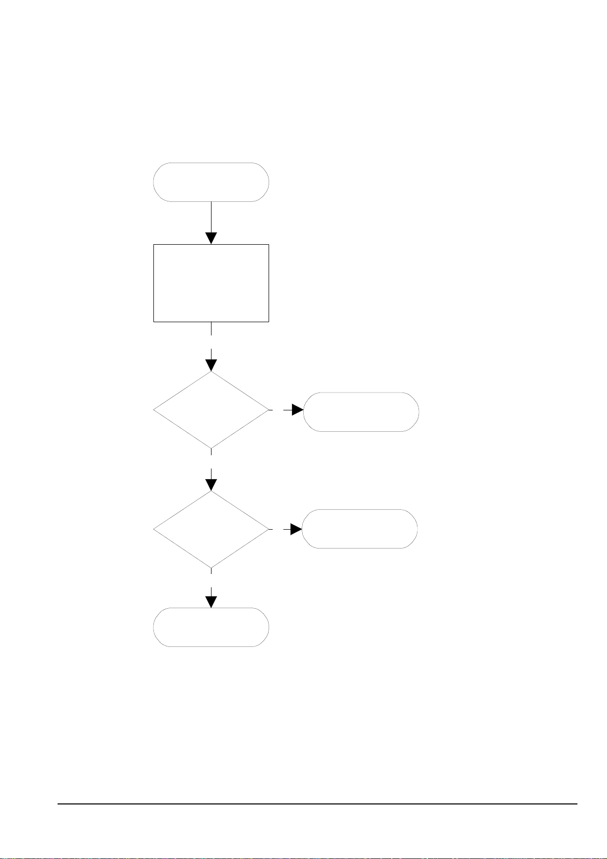
SIMCARD FAULTS
"Insert SIMcard"
Check mechanical
appearance of SIMflex
GEM-1, change if necessary
nOK
7 (29)
Check
signals at E400:
pin90 SIMreset
pin91 SIMdata
pin92 VSIM
pin94 SIMclk
nOK
Check voltage at
E400 pin 93, 4.8VDC
nOK
Check values around
V370
OK
OK
Check SIMlines for
disconnections or
shorts to GND
Change E400
© NMP 2001
Checked by:
Customer Care Training Group
Approved by:
SCCE
Page 8
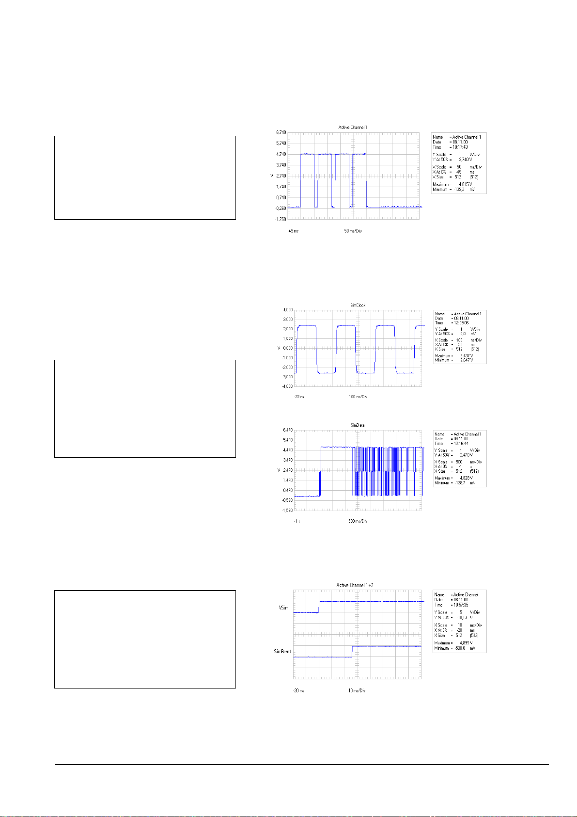
VSIM after switching on the phone without
nokia
CONFIDENTIAL
RAE/K-1 Repairhints
Service & Competence Center Europe
Introduction Version 1.0 Approved
Customer Care Training Group Date 05.04.2001
SIMcard. E 400 pulses up VSIM four times
to an amplitude of 5 Volt.
8 (29)
If the phone is switched on with SIMcard Vsim keeps on 5 Volt expected that SIMcard is not dirty or damaged.
Note that SIMClock and SIMData are only
present when SIMcard is active, for
example when phone registers to network.
Some SIMcards do not allow to switch off
SIMClock but the clock-frequency can be
reduced from 3.25MHz to 1.625MHz
if SIMcard is not used.
SIMReset is low-active, that means that
the Simcard will be reseted when SIMReset
is 0 Volt.
This is the case after switching on the
phone. While VSIM is already high,
SIMReset keeps low for a few milliseconds
– in this time the card will be reseted.
© NMP 2001
Checked by:
Customer Care Training Group
Approved by:
SCCE
Page 9

nokia
CONFIDENTIAL
RAE/K-1 Repairhints
Service & Competence Center Europe
Introduction Version 1.0 Approved
Customer Care Training Group Date 05.04.2001
SIMflex GEM-1
Check mechanical appearance of flexfoil, change if pads torn off or traces are damaged.
SIMlines faulty
Check connection between
E400 pin 90 and X212 pin 7 (100 Ohm, R331).
E400 pin 91 and X212 pin 9 (100 Ohm, R338).
E400 pin 94 and X212 pin 6 (68 Ohm, R330).
E400 pin 92 and X212 pin 8 (resistance is 1800 Ohm, to ensure functionality check also V330/331! ).
Check resistance of SIMlines to GND at X212, value shouldn’t decrease 100kOhm.
E 400 faulty
If SIMlines keep inactive even though SIMcard is inserted, Sim-Flex is ok, SIMlines
have no shorts to ground and voltage at E400 pin 93 is 4.8 Volt, it is necessary to change E400.
Note that you have to realign phone values after changing E400.
9 (29)
© NMP 2001
Checked by:
Customer Care Training Group
Approved by:
SCCE
Page 10

Check voltage divider R232/233
Check voltage divider R263/264
Check R202, R206/207
nokia
CONFIDENTIAL
RAE/K-1 Repairhints
Service & Competence Center Europe
Introduction Version 1.0 Approved
Customer Care Training Group Date 05.04.2001
NOT CHARGING
If it is necessary to take measurements in the charging-circuit you have the possibility to activate
charging-mode in the service-jig by closing SW 1!
Nothing happens if charger is connected
First check X121 and PAR-1 if soiled or oxidized.
Check Vcharge-line for disconnections. Charger-voltage is supplied via connector X121,
over L970 / V970 (overvoltage-protection, located on PDA-board) to board-to-board connector X102/201 and
from there to V250/251, which are responsible for the fault in most cases.
If charger-voltage is ok at V250 or fault persists after changing V250/251, check CHRDET at E400
Pin 97 (~ 4V DC when charging active).
“Not charging“ appears on LCD
Calibrate battery/charger voltage with PCLocals under CMT Testing and Adjustments/Adjustments/
Battery & Charge Voltage Adjustment, values should be ~ 300 for charge voltage and ~ 600 for
battery voltage. If any AD-value is out of reference, check corresponding voltage-divider (see table below). If
calibration is ok but charging still not possible, check AD converters for Battery temp/type with PCLocals under
CMT Testings and Adjustments/Logic Controls/Read AD-Converters.
Battery voltage ~ 720*
Charger voltage ~ 360*
Battery temperature ~ 430
Battery type ~ 600 Check R208/209
* The AD-values of battery/charger voltage in the table differ from the values in calibration because
calibration is done with 6 Volt while AD-converters are read with a battery voltage of 7.2 Volt.
If charging is possible when communicator is switched on but charger is not recognized in off-state mode,
check voltage at N230 pin 11, which is normally 1.7V DC. The only function of CHRDETI line is to get phone from
off-state mode into acting-dead mode (phone is powered up but to the user it seems that phone is still switched
off, only the battery indicator is scrolling). If there is a disconnection in CHRDETI-line, above mentioned fault will
appear.
AD-value reference Possible reason if AD-value is not ok
change N230 or E200
change E200
change N230 or E200
check BATDET line for overload or disconnection
10 (29)
© NMP 2001
Checked by:
Customer Care Training Group
Approved by:
SCCE
Page 11

nokia
CONFIDENTIAL
RAE/K-1 Repairhints
Service & Competence Center Europe
Introduction Version 1.0 Approved
Customer Care Training Group Date 05.04.2001
NOT CHARGING
"Not charging"
appears if charger is
connected
11 (29)
Calibrate
Charger/batt.voltage
with PCLocals
nOK
OK
Check AD_converters with
PCLocals
Try to charge after
calibration
nOK
Battery voltage out of limits
OK ~ 720
Charge voltage out of limits
OK ~ 360
nOK
nOK
Check Vcharge line
for disconnections
Check voltage divider
R232/233 or change
N230, E200
Check voltage at
V250
nOK
OK
Check voltage divider
R263/264, change
E200
© NMP 2001
Battery temperature out of
limits
OK ~ 430
Battery type out of limits
OK ~ 600
Checked by:
nOK
nOK
Check R202/206/207,
change N230/ E200
Check R208/209
check BATDET-line
for overloading
Customer Care Training Group
Approved by:
SCCE
Page 12

nokia
CONFIDENTIAL
RAE/K-1 Repairhints
Service & Competence Center Europe
Introduction Version 1.0 Approved
Customer Care Training Group Date 05.04.2001
SELFTEST FAILED
If “Selftest failed“ appears on LCD, MCU (located on MCM1) is able to work and the watchdog of
PSL (N230) can be served.
To get more information about the fault use PCLocals: initialise CMT to local mode and choose
CMT Power up Selftests.
Try to flash CMT-module in case of failed selftests like MCU DSP code download or similar.
In most cases of Selftest failures one of the two multichip-modules E200 / E400 is defect. It is also
possible that one defect MCM damages the other, so that you have to change both MCMs in case
of doubt.
After changing E200 it is necessary to flash CMT-part. Then you have to write back product-code and
HW version, only after this procedure it is possible to write back the IMEI.
Don`t forget to realign RX/TX-values, because tuning values will be lost after changing E200
Note: Changing of E200 requires IMEI reconstruction process for DCT 1 phones
In case of Selftest failures which appears from time to time check DSP-oscillator. It is enabled by ASIC
(Check E400 pin 88, 4.8V DC).
Critical parts are the crystal G300, coil L300 and transformer T300. If it is necessary to change the crystal,
take care not to destroy L300, which is thermical sensitive!
12 (29)
© NMP 2001
Checked by:
Customer Care Training Group
Approved by:
SCCE
Page 13

nokia
RAE/K-1 Repairhints
Service & Competence Center Europe
Customer Care Training Group Date 05.04.2001
CONFIDENTIAL
Introduction Version 1.0 Approved
CMT MODULE DOES NOT SWITCH ON
In this case check first of all the fault with the normal battery, do NOT connect a service-battery
to the phone. If the CMT-module does not switch on disassemble it and check resistance of capacitors
C763 and C790-793. If resistance of every capacitor is ok, you can connect phone to a service-battery
to check current consumption – the use of other tools may result in burnt traces !
Off state current should be ≤ 2mA, sleep mode current ≤ 20mA, call mode current varies
between 200mA and 600mA (depends on TX powerlevel and lights).
Note: If module is placed in service-jig, deactivate the PDA-module by closing S170, before powering on CMT with
the powerswitch!
It is also not possible to switch on CMT of an assembled communicator with an open lid; you can check
state of lid with PCLocals under CMT Testings and Adjustments/Logic Controls/Read AD Converters in
local mode: Cover information with open lid ~ 870, closed ~ 100.
13 (29)
If CMT does not switch on, it can also be necessary to update the CMT software.
Because of two different CMT-modules GE-8/GE-9 you have to check out the MCU internal software version.
This is necessary to update the different versions with the matching version of CMT-software,
for example MCU int. SW 2.16 with ext. SW GE8_216.502 and MCU int. SW 2.17 with ext. SW GE8_217.502
If there is no possibility to read out MCU int. SW, try to flash several times with the different versions.
How to carry out the upgrade procedure of the CMT side SW see also SB-005.
Note that it is necessary to retune RSSI if CMT-SW has been upgraded to version GE8_216.502 / GE8_217.502.
Due to GEOS Operating System licence agreement it is NOT ALLOWED to upgrade Nokia 9000 to
Nokia 9000i by using Nokia 9000i Flash (CMT or PDA) SW!
© NMP 2001
Checked by:
Customer Care Training Group
Approved by:
SCCE
Page 14

nokia
CONFIDENTIAL
RAE/K-1 Repairhints
Service & Competence Center Europe
Introduction Version 1.0 Approved
Customer Care Training Group Date 05.04.2001
CMT DOES NOT SWITCH ON
Does not
switch on
14 (29)
Check if PWR
consumption is fixed
or about 500mA
No
Check Vbatt at
N230, pin 5,20
OK
Check DETin 1.8VDC
at N230, pin 12
OK
Check that
XPWRon at N230 pin 10
decreases to 0 if
PWRswitch is pressed
OK
Check VL1 4.8V DC
at C241
Yes
nOK
nOK
nOK
nOK
Check Vbatt line for
shorts to GND or try
to flash CMT-module
Check
X202,L200/202
Check Voltage divider
R230/231
Check S36, X001,
R984/985, V130,
X102/201
Check/change L230,
V230, N230
OK
Check Vref 4.65VDC
+/-2% at C247
OK
Check MCUCLK at
E200 pin 85, 26MHz,
5Vpp squarewave
nOK
nOK OK
Check Vref-line for
overloading, change
N230
Check 26MHz Clk at
E400 pin 13, 5.5V
squarewave
nOK
OK
Check XRES 4.8VDC
at E400 pin 96
OK OK OK
nOK
Change N230 Check/change E400 Check/change E200
Check RESETX 4.8V
at E400 pin 112
nOK
Check values around
B800, also check
D300/301
Check/change E400
Check XPWROFF at
E200 pin 22, 5Vpp
squarewave
nOK
Powerunit is ok
© NMP 2001
Checked by:
Customer Care Training Group
Approved by:
SCCE
Page 15

nokia
RAE/K-1 Repairhints
Service & Competence Center Europe
Customer Care Training Group Date 05.04.2001
CONFIDENTIAL
Introduction Version 1.0 Approved
SWITCHES OFF INTERMITTENT
12
If the communicator switches off itself after turning power on while message „recharge battery“ appears
on CMT-display, check voltage at E200 pin 53, should be 3.6V DC. If voltage is not ok, check VBATDETline between N230 pin 23 and E200 pin 53 for shorts to ground or disconnection. Check also voltage divider
R232/233, change N230 or E200 if necessary.
Note that you have to flash CMT-part, write back phone data and realign phone values when changing
E200 because it contains both Flash and EEPROM!
12.87
If the communicator intermittent switches off itself
and the symptom can be reproduced by moving the
battery sideways, check that the space between the
right edge of connector X202 and the chassis is
0.5mm. If distance is not ok, try to correct it by
opening screws of shield and chassis and push CMTmodule to the left, check gap after tightening the
screws. If this does not work, replace connector
X202.
15 (29)
© NMP 2001
Checked by:
Customer Care Training Group
Approved by:
SCCE
Page 16

nokia
CONFIDENTIAL
RAE/K-1 Repairhints
Service & Competence Center Europe
Introduction Version 1.0 Approved
Customer Care Training Group Date 05.04.2001
PDA – MODULE FAULTY
Because of very detailed troubleshooting diagrams in the service manual we will describe in the
following only the most common faults of the PDA-module.
For more information refer to Servicemanual chapter 8 (Faultfinding & Disassembly).
If you suppose a faulty FLASH, never change D163. This part contains the boot-code, which PDA needs to
start. Without boot-code PDA won`t work, it is even impossible to ping PDA or make SW-update.
As you won`t be able to rewrite boot-code, you have to swap module.
PDA-module not initialising
Check Communicator in temperature chamber at +5°C for 10min. if fault occurs only from time to time.
If PDA module does not initialize after temperature check or hangs up, make HW-update as described in SB017.
Other possibilities if HW-update does not solve the problem :
Check connector X121 for cold solderings, if bent or soiled. Check also V970, L970 and C970
PDA does not start
Check state of lid with PCLocals: CMT Testings and Adjustments/Logic Controls/Read AD Converters
in local mode: Cover information with open lid ~ 870, closed ~ 100. If value is fixed on ~ 100, check
mechanical/electrical appearance of S170,also check R150/151. Probably force of magnet is too low.
Check Vb 7.2V DC at both sides of L80, change coil if necessary.
Check voltage at C89, 22V DC. If not ok, check R77 for defect or cold soldering, change N83 if necessary
Check R184 (33 Ohm) for defect or broken solderings
Check voltage at connector X010 pin1 on UI-module, which is 3.3V DC when PDA is active.
If not ok, check R926/927, also check flex foil of PDA-LCD, which can be easily damaged while disassembling.
16 (29)
Check 32.768kHz sinewave at D130
pin 86. In most cases the crystal
B130 is defect if signal is not ok.
In some cases it can be necessary to format file system. This can be done with service-software
or by pressing Shift + Esc + F and installing the battery to boot the communicator.
Keep the keys pressed until you get a screen to confirm the formatting.
Note that formatting will remove all user-generated data. You should save user`s data before proceed !
PDA does not start after screensaver was active/standby-problems
This fault occurs often, if Communicator is checked in temperature chamber at +5°C for 10min.
In this case HW-update as described in SB17 is necessary
Change R120- R129 from 22kOhm to 4.7kOhm and replace D130 with new part (code 4370339)
Screensaver Error GEOS.ini / internal error
It is necessary to format file system and make SW-update.
(press Shift + Esc + F and install battery to boot the communicator; all user-generated data will be lost!).
Date & time lost after battery removal
Check that voltage of G87 is ≥ 2.8 VDC. Change if voltage is lower than 2.8V – G87 is NOT chargeable!
PDA Display failures
Bad or flickering LCD – Display driver defect – change Display
LCD Contrast problems – check/change R93, R97
© NMP 2001
Checked by:
Customer Care Training Group
Approved by:
SCCE
Page 17

nokia
CONFIDENTIAL
RAE/K-1 Repairhints
Service & Competence Center Europe
Introduction Version 1.0 Approved
Customer Care Training Group Date 05.04.2001
POOR OR NO SERVICE (RAE–1)
First of all: Check the appearance of all mechanical components, connectors and connections like coax cable and
connectors X503 / X501 / X035.
If the mechanical condition is OK, calibrate RX/TX values to find out the trouble.
RX failed
Check the TX-spectrum at standard frequency (902MHz /CH 60). If spectrum is ok, check the following points.
Measurements taken by input signal 947 MHz / CH 60 and level –40dBm
Check Data signals coming from MCM2
SCLK : 3Vpp squarewave at R823
SDATA : 4.5Vpp squarewave at R824
SENA1 : 3Vpp squarewave at R825
PDATA0 : 5Vpp squarewave at R507
Change MCM2 / E400 if one or more of these signals failed
If these signals are ok, check the reference frequency of 26 MHz at N820, pin 8, frequency deviation ≤ 50Hz.,
change B800 if necessary.
Check also VREF 4.65VDC ± 2% (from PSL)
Check also VPLL, VHLO, VRX, RXPWR and SYNTHPWR: 4.7V, see diagrams at page #26 and / or change N601 if
necessary.
Check UHF oscillator frequency 1018 MHz at N820, pin 6, change G001 if necessary
Check VHF oscillator frequency 232 MHz at N820, pin 15
Check 947 MHz at Z500, RX pin ~ -50dBm
Check 947 MHz at V501, Base pin ~ -70dBm and output at collector pin ~ -52dBm
Check 947 MHz in and out at Z505, attenuation ≤ 5dBm
Change corresponding components
Check UHF 1018 MHz at V511
Check IF 71 MHz at V511 / L511 ~ -65dB / change V511 if necessary
Check IF 71 MHz at L542 (input of Z541) approximately –37dBm and
output of Z541 with ≤20dBm attenuation at C545 / C546
Check IF 71 MHz at N551, pin 1,2 ~ -56dBm
Check IF 13 MHz at N551 out, pin 7 and in at pin 9,10
Check 13 MHz RXI / RXQ ~ -21dBm at N551, pin 13,12
Change Z551 / N551 if necessary
Note that the measured RF values depend on used measurement equipment.
17 (29)
© NMP 2001
Checked by:
Customer Care Training Group
Approved by:
SCCE
Page 18

nokia
CONFIDENTIAL
RAE/K-1 Repairhints
Service & Competence Center Europe
Introduction Version 1.0 Approved
Customer Care Training Group Date 05.04.2001
RAE-1
18 (29)
Change PSL N230
Change N601
nOK
nOK
RX FAIL
Check
SCLK at R823
SDATA at R824
SENA1 at R825
PDATA0 at R507
Check VREF: 4.65V (+-2%)
Check VBATT at N601: 7.2V
Check VPLL, VHLO, VTX,
TXPWR, all ~ 4.7V
Check:
TXIN at R551
TXIP at R553
TXQP at R554
TXQN at R556
OK
Check AFC at R800: ~2.7V
OK
OK
Check 26MHz at C803
OK
OK
Check SYNTHPWR at R601
OK
OK
Check UHF 1018 MHz at
OK
N820, pin6
nOK
nOK
nOK
nOK
Change E400
Change B800
Check/change E400
Change G001
Check values at V840
and 841, change N820 if
Check/change
components in line to
Change Z541 if
necessary
necessary
V511
Check VHF 232MHz at N820,
pin15
Check UHF 1018MHz at
V511
Check IF71 MHz at L542 and
Values at C545/546
Check IF 13MHz at N551/
pin 7 output and pin 9,10
input
OK
Check 947 MHz at V501,
check 947 MHz at Z505
OK
OK
OK
OK
OK
OK
OK
in&out (att~5dB)
Check IF 71MHz at V511 and
L511
Check 71MHz at input N551
pin1,2
Check RX I/Q values at
N551, pin 12/13
nOK
nOK
nOK
Check C506, change
corresponding
components
Change V511
Check/change
components in lines
to N551
Change Z551/N551
corresponding on
failed signal
© NMP 2001
Checked by:
Customer Care Training Group
Approved by:
SCCE
Page 19

nokia
CONFIDENTIAL
RAE/K-1 Repairhints
Service & Competence Center Europe
Introduction Version 1.0 Approved
Customer Care Training Group Date 05.04.2001
LOW OR NO TX POWER (RAE–1)
First of all check always the appearance of all mechanical components, connections or connectors like coax cable,
and connectors X503 / X501 / X035.
TX failed
Measurements taken by active unit TX channel 60, 902MHz
Check TX I/Q and Data signals coming from MCM2
TXIN : 400mVpp squarewave at R551
TXIP : 400mVpp squarewave at R553
TXQP : 400mVpp squarewave at R554
TXQN : 400mVpp squarewave at R556
SCLK : 3Vpp squarewave at R823
SDATA : 4.5Vpp squarewave at R824
SENA1 : 3Vpp squarewave at R825 and/or see diagrams at page 26
Change MCM2 / E400 if one or more of these signals failed
If these signals are ok check the reference frequency of 26 MHz at N820, pin 8, frequency deviation ≤ 50Hz.
change B800 if necessary
Check also VREF 4.65VDC ± 2% (from PSL).
Check also VPLL, VHLO, VTX, TXPWR and SYNTHPWR 4.7V
see diagrams at page #26 and / or change N601 if necessary
Check UHF oscillator frequency 1018 MHz at N820, pin 6, change G001 if necessary
Check VHF oscillator frequency 232 MHz at N820, pin 15
Check VHF 232 MHz at N551, pin 16,19 ~ -26dBm
Check ½ VHF 116 MHz output at N551, pin 28 ~-30dBm, change N551 if necessary
Check ½ VHF 116 MHz at C710 (~ -12dBm) and at V702 (~ -25dBm)
Check UHF 1018 MHz at V702 ~ -10dBm
Check 902 MHz at V710, Basis pin ~ -39dBm and collector pin ~ -20dBm
Check 902 MHz at Z713 input (~ -23dBm) and output (~ -26dBm)
Check VBATT 6.5V before and after R743 and R756, change corresponding component
Check 902 MHz at V725 / V738 / V756 and V768 in- & output
If V756/V768 defect for itself, change the second one as well in every case
Check 902 MHz at Z500 (~ -12dBm), change corresponding component(s)
19 (29)
© NMP 2001
Checked by:
Customer Care Training Group
Approved by:
SCCE
Page 20

nokia
CONFIDENTIAL
RAE/K-1 Repairhints
Service & Competence Center Europe
Introduction Version 1.0 Approved
Customer Care Training Group Date 05.04.2001
RAE-1
20 (29)
Change PSL N230
Change N601
nOK
nOK
TX FAIL
Check
SCLK at R823
SDATA at R824
SENA1 at R825
Check VREF: 4.65V (+-2%)
Check VBATT at N601:
7.2VDC
Check VPLL, VHLO, VTX,
TXPWR, all 4.7V
Check:
OK
OK
OK
OK
OK
OK
OK
OK
OK
TXIN at R551
TXIP at R553
TXQP at R554
TXQN at R556
Check AFC at R800:
0.2-4.6VDC
Check 26MHz at C803
freq.-devitation <=50Hz
Check SYNTHPWR at R601
Check UHF 1018 MHz at
N820, pin6
nOK
nOK
nOK
nOK
Change E400
Change B800
Check/change E400
Change G001
Change cor. comp.If
V756/768 def.,change
2nd one too
Check VHF 232MHz at N820,
pin15 and values at N551,
Check 1/2 VHF 116MHz at
C710 (~-12dBm) and V702
Check 902 MHz at Z713
nOK
pin 16/19
(~-25dBm)
input ~-23dBm, output
~-26dBm
Check 902 MHz at
V725/738/756/768
OK
Check 1/2 VHF 116MHz at
OK
OK
OK
OK
OK
OK
OK
N551, pin28
Check UHF 1018MHz at
V702 ~-10dBm, check 902
MHz at V710 basis
~-39dBm/ collector ~-20dB
Check VBATT 6.5V before and
after R743/756
Check 902 MHz at Z500
~-12dB
nOK
nOK
nOK
Change N551
Change def.
component
Change
corresponding
components in line
© NMP 2001
Checked by:
Customer Care Training Group
Approved by:
SCCE
Page 21

nokia
CONFIDENTIAL
RAE/K-1 Repairhints
Service & Competence Center Europe
Introduction Version 1.0 Approved
Customer Care Training Group Date 05.04.2001
POOR OR NO SERVICE (RAK–1)
First of all check always the appearance of all mechanical components, connections or connectors like coax cable,
and connectors X503 / X501 / X035.
If the mechanical condition is OK, calibrate RX/TX values to find out the trouble.
RX failed
At first check if there is a TX-spectrum is standard frequency of 1747,4MHz /CH 698
If TX spectrum and an RSSI calibration not possible – probably MCM2 / E400 faulty
If spectrum ok, check the following points…
Measurements taken by input signal 1842,4MHz / CH 698 and level –40dBm
Check Data signals coming from MCM2
SCLK : 3Vpp squarewave at R823
SDATA : 4.5Vpp squarewave at R824
SENA1 : 3Vpp squarewave at R825
PDATA0 : 5Vpp squarewave at R507
and/or see diagrams at page #26, check also AFC at R800, 0.2-4.6VDC.
Change MCM2 / E400 if one or more of these signals failed
If these signals are ok, check the reference frequency of 26 MHz at N820, pin 8 frequency deviation ≤ 50Hz,
change B800 if necessary.
Check also VREF 4.65VDC ± 2% (from PSL),
Check also VPLL, VHLO, VRX, RXPWR and SYNTHPWR 4.7V.
See diagrams at page #26 and / or change N601 if necessary
Check UHF oscillator frequency 1529.4 MHz at N820, pin 5, change G001 if necessary
Check VHF oscillator frequency 400MHz at N820, pin 16.
Check 1842.4MHz at Z500, RX pin ~ -50dBm.
Check 1842.4MHz at V501, Basis pin ~ -70dBm and output at collector pin ~ -52dBm.
Check 1842.4MHz in and out at Z505, attenuation ≤ 5dBm.
Change corresponding components, check UHF 1529.4MHz at V511.
Check 1st IF 313MHz at V511 / L511 ~ -65dBm / change V511 if necessary, check 313MHz at V531 / L530.
Check 87MHz at L531 – if not ok – check / change V531.
nd
Check 2
IF 87MHz at L542 (input of Z541) approximately –37dBm and output of Z541 with ≤ 20dBm
attenuation at C545 / C546.
Check 2nd IF 87MHz at N551, pin 1,2 ~ -56dBm – not ok check lines back to Z541
Check 3rd IF 13 MHz at N551 out, pin 7 and in at pin 9,10
Check 13 MHz RXI / RXQ ~ -21dBm at N551, pin 13,12, change Z551 / N551 if necessary
21 (29)
© NMP 2001
Checked by:
Customer Care Training Group
Approved by:
SCCE
Page 22

nokia
CONFIDENTIAL
RAE/K-1 Repairhints
Service & Competence Center Europe
Introduction Version 1.0 Approved
Customer Care Training Group Date 05.04.2001
RAK-1
RX FAIL
Check
SCLK at R823
SDATA at R824
SENA1 at R825
PDATA0 at R507
OK
Check AFC at R800
0.2-4.6VDC
nOK
Change E400
22 (29)
Change PSL N230
Change N601
Check values at V840
and 841, change N820 if
necessary
Check/change
components in line to
V511
nOK
Check VREF: 4.65V (+-2%)
Check VBATT at N601: 7.2V
nOK
nOK
Check VPLL, VHLO, VTX,
Check VHF 400MHz at N820,
nOK
Check 313MHz at V511 and
TXPWR, all 4.7V
pin15
L511
OK
OK
OK
OK
OK
OK
OK
OK
OK
OK
Check 26MHz at C803
frequency deviation
+- 50Hz
Check SYNTHPWR at R601
Check UHF 1529.4 MHz at
N820, pin6
Check 1842.4 MHz at V501
and Z505 in&out (att<5dB)
Check IF 87MHz at V531 and
values at C545/546
nOK
nOK
nOK
nOK
nOK
Change B800
Check/change E400
Change G001
Check C506, change
corresponding
components
Change V511
Change Z541 if
necessary
© NMP 2001
nOK
Check IF 87MHz at input
N551, pin 1,2
OK
Check IF 13MHz at N551
pin7 output and pin 9,10
OK
Check RXI/Q signals at
N551/pin 12,13
OK
Check RX I/Q signals at
N551, pin 12/13
OK
Checked by:
Customer Care Training Group
input
nOK
nOK
Check/change
components in lines
to N551
Change Z551/N551
corresponding on
failed signal
Approved by:
SCCE
Page 23

nokia
RAE/K-1 Repairhints
Service & Competence Center Europe
Customer Care Training Group Date 05.04.2001
CONFIDENTIAL
Introduction Version 1.0 Approved
LOW OR NO TX POWER (RAK–1)
First of all check always the appearance of all mechanical components, connections or connectors like coax cable,
and connectors X503 / X501 / X035.
Measurements taken by active unit TX channel 698, 1747.4MHz
Check TX I/Q and Data signals coming from MCM2
TXIN : 400mVpp squarewave at R551
TXIP : 400mVpp squarewave at R553
TXQP : 400mVpp squarewave at R554
TXQN : 400mVpp squarewave at R556
SCLK : 3Vpp squarewave at R823
SDATA : 4.5Vpp squarewave at R824
SENA1 : 3Vpp squarewave at R825 and/or see diagrams at page 26
Change MCM2/E400 if one or more of these signals failed.
If these signals are ok check the reference frequency of 26 MHz at N820, pin 8 frequency deviation ≤ 50Hz
Change B800 if necessary.
Check also VREF 4.65V ± 2% (from PSL),
Check also VPLL, VHLO, VTX, TXPWR and SYNTHPWR: 4.7V
See diagrams at page #26 and / or change N601 if necessary.
Check UHF oscillator frequency 1529.4MHz at N820, pin 5, change G001 if necessary.
Check VHF oscillator frequency 400MHz at N820, pin 16.
Check VHF 400MHz at N551, pin 16,19: (~ -26dBm)
Check ½ VHF 200MHz output at N551, pin 28: (~-30dBm), change N551 if necessary
Check ½ VHF 200MHz at C710 (~ -12dBm) and at V702 (~ -25dBm)
Check UHF 1547.4MHz at V702 ~ -10dBm.
Check 1747.4MHz at V710, Base pin ~ -39dBm and collector pin ~ -20dBm.
Check 1747.4MHz at Z713 in & out (attenuation ≤10dBm).
Check VBATT 7.2V at V738 and V755, R768, change corresponding component.
Check 1747.4MHz at V725 / V738 / V756 and V768 in- & output.
If V756/V768 defect for itself, change the second one as well in every case.
Check C772, C775, C776, and C774 – change if necessary.
Check 1747.4MHz at Z500 (~ -12dBm), change corresponding component(s).
23 (29)
© NMP 2001
Checked by:
Customer Care Training Group
Approved by:
SCCE
Page 24

nokia
CONFIDENTIAL
RAE/K-1 Repairhints
Service & Competence Center Europe
Introduction Version 1.0 Approved
Customer Care Training Group Date 05.04.2001
RAK-1
24 (29)
Change E400
Change PSL N230
Change N601
nOK
nOK
nOK
TX FAIL
Check
SCLK at R823
SDATA at R824
SENA1 at R825
Check VREF: 4.65V (+-2%)
Check VBATT at N601:
7.2VDC
Check VPLL, VHLO, VTX,
TXPWR, all 4.7VDC
Check:
OK
OK
OK
OK
OK
OK
OK
OK
OK
TXIN at R551
TXIP at R553
TXQP at R554
TXQN at R556
Check AFC at R800:
0.2-4.6VDC
Check 26MHz at C803
frequenz-devitation
+-50Hz
Check SYNTHPWR at R601
Check UHF 1529.4 MHz at
N820, pin5
nOK
nOK
nOK
nOK
Change E400
Change B800
Check/change E400
Change G001
Change corresponding
components in line
Change cor. comp.If
V756/768 def.,change
back
2nd one too
Check VHF 400MHz at N820,
pin16 and values at N551,
Check 1/2 VHF 200MHz at
nOK
Check 1747.4 MHz at Z713
nOK
V725/738/756/768, check
pin 16/19
V702
V710 (att. <=10dBm)
Check 1747.4 MHz at
C772/775/776/774
OK
Check 1/2 VHF 200MHz at
OK
OK
OK
OK
OK
OK
OK
N551, pin28
Check UHF 1547.4 MHz at
V702
Check VBATT 7.2V at
V738/755
Check 1747.4 MHz at Z500
~-12dBm
nOK
nOK
nOK
Change N551
Change def.
component
Change
corresponding
components in line
© NMP 2001
Checked by:
Customer Care Training Group
Approved by:
SCCE
Page 25

nokia
CONFIDENTIAL
RAE/K-1 Repairhints
Service & Competence Center Europe
Introduction Version 1.0 Approved
Customer Care Training Group Date 05.04.2001
Spectrum out of range / no spectrum (noise only)
First of all check always the appearance of all mechanical components, connections or connectors like coax cable,
and connectors X503 / X501 / X035.
Check 26 MHz reference frequency at N820, pin 8
Change B800 if frequency deviation higher than +/-50Hz
Check VREF 4.65VDC ± 2% at C806
Change N230 if VREF fails
Check TX I/Q signals coming from MCM2 / E400
TXIN : 400mVpp squarewave at R551
TXIP : 400mVpp squarewave at R553
TXQP : 400mVpp squarewave at R554
TXQN : 400mVpp squarewave at R556
25 (29)
Check TXC (at R574) and TXP (at R571) signals to N551
See diagrams at pages #26+27
Check soldering / change N551 if necessary
Check soldering / change E400 if necessary
© NMP 2001
Checked by:
Customer Care Training Group
Approved by:
SCCE
Page 26

nokia
CONFIDENTIAL
RAE/K-1 Repairhints
Service & Competence Center Europe
Introduction Version 1.0 Approved
Customer Care Training Group Date 05.04.2001
SIGNAL CHARTS
26 (29)
© NMP 2001
Checked by:
Customer Care Training Group
Approved by:
SCCE
Page 27

nokia
CONFIDENTIAL
RAE/K-1 Repairhints
Service & Competence Center Europe
Introduction Version 1.0 Approved
Customer Care Training Group Date 05.04.2001
27 (29)
© NMP 2001
Checked by:
Customer Care Training Group
Approved by:
SCCE
Page 28

nokia
CONFIDENTIAL
RAE/K-1 Repairhints
Service & Competence Center Europe
Introduction Version 1.0 Approved
Customer Care Training Group Date 05.04.2001
28 (29)
© NMP 2001
Checked by:
Customer Care Training Group
Approved by:
SCCE
Page 29

nokia
CONFIDENTIAL
RAE/K-1 Repairhints
Service & Competence Center Europe
Introduction Version 1.0 Approved
Customer Care Training Group Date 05.04.2001
CHANGE HISTORY
Originator State Version Date Comment
CC-TrainingGroup
CC-TrainingGroup
Draft 0.1
Approved 1.0 05.04.2001 First approved version. Comments of repairgroup added.
16.03.2001
First draft version for the repair group
29 (29)
© NMP 2001
Checked by:
Customer Care Training Group
Approved by:
SCCE
 Loading...