

Page 1
NHM-4/NHM-4NX 8910/8910i Repairhints
Customer Care Europe, Middle East & Africa Version 2.0 Approved
SCCE Training Group Date 03.06.2003
CONFIDENTIAL 1 (16)
Repair Hints
Service Level 3 & 4
8910/8910i
© NMP 2003
NHM-4/NHM-4NX
Checked by:
SCCE Training Group
Approved by:
SCCE
Page 2
CONFIDENTIAL 2 (16)
NHM-4/NHM-4NX 8910/8910i Repairhints
Customer Care Europe, Middle East & Africa Version 2.0 Approved
SCCE Training Group Date 03.06.2003
General
-How to use this document
Put the colored schematics behind this manual.
Now you are able to follow these specifictions with graphical layouts and it is easier for you to find the components
and measuring points.
-General handling
Be very careful when disassembling the NHM-4/NHM-4NX while removing the grip module: Do not scratch it. Refer to
disassembling instructions in the service manual of NHM-4/NHM-4NX.
Both phones, 8910 and 8910i has the same typ (NHM-4NX) printed on the label.
Pay attention on the different sales names, when relabeling the phone
-Component charactaristics
Some components contain important data.
Several steps described are only feasible if you are able to reflash/ realign the phone and/ or rewrite IMEI/ SIMlock in
certain cases. Please pay attention to separate notes.
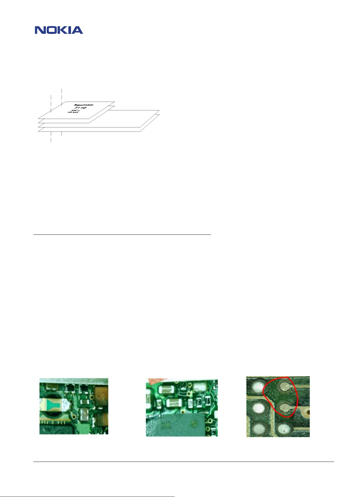
-Broken balls / underfill, µBGAs
All replaceable (not underfilled) µBGA components must be renewed after removing. Reflow with uncontrolled hot air
fan is strictly forbidden! It is also not recommended only to reflow the old µBGA using a µBGA rework station!
must only be soldered with NMP approved µBGA rework machines (e.g. Zevac / OK-Metcal / Martin) to get durable
soldering joints.
After removing a µBGA check soldering points, rework oxidated solderings (broken balls) carefully by tinplating these
areas with few flux and a hot soldering iron if necessary. Before placing a new component remove the tin and Use only
recommended flux type and an appropriate amount of it – avoid drowning the PWB in flux as this will result in
additional faults!
Also check underfilled parts for broken underfill material below. In this case carefully evaluate possible repair actions as
the phone probably was exposed to strong mechanical stress.
“Rework” done with uncontrolled hot-air PWB drowned in flux Oxidated solderings
.
µBGA
© NMP 2003
Checked by:
SCCE Training Group
Approved by:
SCCE
Page 3

CONFIDENTIAL 3 (16)
NHM-4/NHM-4NX 8910/8910i Repairhints
Customer Care Europe, Middle East & Africa Version 2.0 Approved
SCCE Training Group Date 03.06.2003
-PCB handling & cleaning
To avoid damages of PWB and/ or components through electrostatic discharging, handle the module in
ESD-suitable cases only. When handling PWBs outside an ESD-bag always wear ESD-wristbands, which must be
connected to earth bonding point. Damage by electrostatic discharge often leads to a module not failing directly but in
a short period of time!
For cleaning only use appropriate materials, do not use scratching or rubbing tools. Useful tools for cleaning are flux
cleaners such as “Kontakt LR” or “Electrolube FLU” in connection with ionized compressed air.
-Screwing, torque
To assemble the phone, use a Torx T6 Plus screwdriver and torque of 17Ncm
-Realign after repair
Characteristics of replacement parts may vary.
To prevent additional faults after repair (e.g. low standby time, losing network etc.) it is necessary to retune phone
values after repair, but never try to cover up a fault by adjusting the phone.
-Fault report in fault log (Phoenix)
It is very important to report all repaired failures in fault log after finishing the complete phone repair.
The report content should only
contain the self-observed fault symptom, except “no fault found”.
In this case the report content should contain the symptom code that is given by the customer
e.g “Does not switch on”(2101) and the fault code“no fault found”(470).
If the symptom code from the customer is not identic to the observed symptom, always use the self-observed symptom
code.
.
© NMP 2003
Checked by:
SCCE Training Group
Approved by:
SCCE
Page 4

NHM-4/NHM-4NX 8910/8910i Repairhints
Customer Care Europe, Middle East & Africa Version 2.0 Approved
SCCE Training Group Date 03.06.2003
CONFIDENTIAL 4 (16)
ESD PROTECTION REQUIREMENTS
Electrostatic discharge can easily damage the sensitive components
of electronic products. Therefore, every Service Partner has to take of
at least some precautions, such as ESD restricted area, floor, table,
covering, chair(s), shoes or wristbands.
For further information refer to the Partner Web site document
“Service Partner Requirements”
example of an electrostatic protected area (EPA) set-up
source: www.armeka.com
example of a workbench set-up
source: www.warmbier.com
example of a workbench and testers
source: http://www.armekaengineering.com
© NMP 2003
Checked by:
SCCE Training Group
Approved by:
SCCE
Page 5

CONFIDENTIAL 5 (16)
NHM-4/NHM-4NX 8910/8910i Repairhints
Customer Care Europe, Middle East & Africa Version 2.0 Approved
SCCE Training Group Date 03.06.2003
IMPORTANT:
This document is intended for use by authorized NOKIA service centers only.
The purpose of this document is to provide some further service information for NHM-4/NHM-4NX 8910/8910i.
It contains a lot of collected tips and hints to find faults and repair solutions easily.
It also will give support to inexperienced technicians.
Saving process time and improving the repair quality is the aim of using this document.
It is based on fault symptoms (listed in "Contents"), followed by detailed description for further analysis.
It is to be used additionally to the service manual, and other service information such as Service Bulletins. For that
reason it does not contain any circuit or schematic diagrams.
All measurements are made using following equipment:
Nokia repair SW: Phoenix
Phoenix Application: A7 2003.9.7.8
Flash SW (CMT): 3.06 (NHM-4/8910)
3.01 (NHM-4NX/8910i)
Test Jig: MJS-39
Docking station: JBV-1
Docking Adapter: MJF-3
Digital Multimeter: Fluke 73
Oscilloscope: Fluke PM 3380A/B
Spectrum Analyzer: Advantest R3162 with an analogue probe
RF-Generator / GSM Tester: CMU 200
While every endeavour has been made to ensure the accuracy of this document, some errors may exist. If the reader
finds any errors, NOKIA should be notified in writing, using following procedure:
Please state:
Title of the document + issue number/date of publication.
page(s) and/or figure(s) of error.
Please send to: Nokia GmbH
Services & Competence Center Europe
Meesmannstr.103
D-44807 Bochum / Germany
Email: training.sace@nokia.com
Copyright © Nokia Mobile Phones.
This material, including documentation and any related computer programs, is protected by copyright, controlled by
Nokia Mobile Phones. All rights are reserved. Copying, including reproducing, modifying, storing, adapting or
translating any or all of this material requires the prior written consent of Nokia Mobile Phones. This material also
contains confidential information, which may not be disclosed to others without the prior written consent of Nokia
Mobile Phones.
© NMP 2003
Checked by:
SCCE Training Group
Approved by:
SCCE
Page 6

NHM-4/NHM-4NX 8910/8910i Repairhints
Customer Care Europe, Middle East & Africa Version 2.0 Approved
SCCE Training Group Date 03.06.2003
CONFIDENTIAL 6 (16)
Contents
PREFACE
ESD Protection 4
Symptom Code List
scratch sound when fast closing of grip module I002 7
Too fast opening of grip module I002 8
Microphone sometimes does not work 9
No Vibra 10
No charging 11
“Insert SIM card” 12
Flowchart “Insert SIM card” 13
Flash update fails (C683) 14
Change History 16
GENERAL 2
© NMP 2003
Checked by:
SCCE Training Group
Approved by:
SCCE
Page 7

CONFIDENTIAL 7 (16)
NHM-4/NHM-4NX 8910/8910i Repairhints
Customer Care Europe, Middle East & Africa Version 2.0 Approved
SCCE Training Group Date 03.06.2003
Scratch sound when fast closing of grip module I002
Pre-Check:
Press the side button to open the Grip module. Now close the grip.
- If a scratch sound is to be heard, follow repair instructions:
o See “scratch sound when fast closing of grip module I002”
Scratch sound when fast closing of grip module I002
If a scratch sound is to be heard while closing the grip module I002, the open/ close mechanism is damaged.
To solve the problem change following items:
I002 grip module C
Change the I007 shield assy to the new one
Note! Use the new shield assy and remove the black plastic tape or black cover behind the battery connector if
necessary. The new shield assy is not matching with the old battery cover (see pictures below). (See SB-021/8910 or SB-
007/8910i)
Remove the black plastic tape or the black plastic cover. Both cover types are possible.
Tape cover Plastic cover
I009 limiter assembly
© NMP 2003
Checked by:
SCCE Training Group
Approved by:
SCCE
Page 8

CONFIDENTIAL 8 (16)
NHM-4/NHM-4NX 8910/8910i Repairhints
Customer Care Europe, Middle East & Africa Version 2.0 Approved
SCCE Training Group Date 03.06.2003
Too fast opening grip module I002
Pre-Check:
Press the side button to open grip module I002.
- If the Grip module opens to fast, follow repair instructions:
o See “Too fast opening grip module I002”
Too fast opening grip module I002
If the grip module opens to fast when pressing the side buttons, change the dumper I020.
Old I020 Damper New
For changing the Damper refer to SB-014 (grip and damper repair instructions)
© NMP 2003
Checked by:
SCCE Training Group
Approved by:
SCCE
Page 9

CONFIDENTIAL 9 (16)
NHM-4/NHM-4NX 8910/8910i Repairhints
Customer Care Europe, Middle East & Africa Version 2.0 Approved
SCCE Training Group Date 03.06.2003
Microphone sometimes does not work
Pre-Check:
Make a call with a working phone. Speak into the faulty phone.
- If nothing is hearable at the working phone, follow the repair instructions:
o See “Microphone sometimes does not work”
Microphone sometimes does not work
If the microphone does not work, probably the flex foil to X100 flex connector is broken, the connector itself is faulty or
one of the components one the PWB does not work.
- First try to change the grip module and test with a working one.
Note! For disassembling instructions refer to service manual NHM-4 8910, chapter “Disassembly and Troubleshooting
Instructions”
- If the problem is solved, probably the flex foil was broken or had no connection to the connector.
Grip module I002
- If the fault persists, check X100 flex connector for mechanical stress, broken solderings or interruptions.
- If the connector is ok but the microphone sometimes does not work, put the PWB into repair Jig MJS-39 and set
phone with Phoenix Service SW to local mode. Enter menu Maintenance/Testing/Audio and Turn Loop on. Measure
at following pins of X100.
MIC: Pin 9 =2.1VDC (Loop on); 0V (Loop off)
XEAR: Pin 11 = 0.8VDC (Loop on); 0V (Loop off)
- If on or both do not work, check lines and components between X100 and UEM for broken solderings or
disconnections and change faulty ones.
Flex foil with connector
© NMP 2003
Checked by:
SCCE Training Group
Approved by:
SCCE
Page 10

NHM-4/NHM-4N
Customer Care Europe, Middle East & Africa
SCCE Training Group Date 03.06.20
CONFIDENTIAL
10 (16)
X 8910/8910i Repairhints
Version 2.0 Approved
03
No Vibra
Pre-Check:
Use a working phone and try to make a call to the faulty one. (Be sure that vibra is set to “on” under the signaling
menu)
- If the ringtone is to be heard but the vibra does not work, follow the repair instructions:
o See “No Vibra”
No Vibra
If the vibra does not work, probably the flex foil to X100 flex connector is broken, the connector itself is faulty or one of
the components on the PWB does not work.
- First try to change the Grip module and test with a working one.
Note! For disassembling instructions refer to service manual NHM-4 8910, chapter “Disassembly and Troubleshooting
Instructions”
- If the problem is solved, probably the flex foil was broken or had no connection to the connector. (See also pictures
in chapter “Microphone sometimes does not work”)
- If the fault persists, measure the voltage at Pin 5 (Vibra (+))=4VDC and Pin 20 (Vibra (-))=4VDC of flex connector.
- If one of the voltages is not ok, check components in Vibra(–) and Vibra(+) line for shorts or disconnections.
- If the voltages are ok, set phone to local mode and enter menu Maintenance/Testing/Vibra. Set
Vibra”enable”/2.9% intensity and press button “write”. Measure with oscilloscope at C101 following signal (See
Figure1)
Figure 1
Set oscilloscope to:
Volt/div: 1V
Time/div: 1ms
- If there is no signal, probably the UEM D200 or the SW is faulty.
- If the signal is ok, disable the vibra and connect a functional vibra to flex connector and change the intensity from
2.9% to 96.9%. Measure the voltage at kathode of V108. The voltage differes between 3.6V and 3.9V (only with
connected vibra).
- If the voltage is around 0V, the V108 diode is faulty.
X100 Flex connector
© NMP 2003
Checked by:
SCCE Training Group
Approved by:
SCCE
Page 11

CONFIDENTIAL 11 (16)
NHM-4/NHM-4NX 8910/8910i Repairhints
Customer Care Europe, Middle East & Africa Version 2.0 Approved
SCCE Training Group Date 03.06.2003
No charging
Pre-Check:
Connect a working phone to the charger (e.g. ACP-7, ACP-8 or ACP-12), and check if the battery indicator of the phone
display is scrolling. If it works, connect the faulty phone to the same charger, and check the battery indicator in the
display.
- If the phone does not charge, follow the repair instructions:
o See “No charging”
No charging
If the charging does not work, probably the flex foil to X100 flex connector is broken, the connector itself is faulty or
one of the components one the PWB does not work.
- First try to change the grip module and test with a working one.
Note! For disassembling instructions refer to service manual NHM-4 8910, chapter “Disassembly and Troubleshooting
Instructions”
- If the problem is solved, probably the flex foil was broken or had no connection to the connector. (See also pictures
under chapter “Microphone sometimes does not work”)
- If the fault “no charging” persists, check lines from X100, Pin 1-4 (for measure points see picture X100 flex
connector under menu “No Vibra”) to UEM for broken soldering or disconnections, and resolder or change faulty
components.
© NMP 2003
Checked by:
SCCE Training Group
Approved by:
SCCE
Page 12

CONFIDENTIAL 12 (16)
NHM-4/NHM-4NX 8910/8910i Repairhints
Customer Care Europe, Middle East & Africa Version 2.0 Approved
SCCE Training Group Date 03.06.2003
“Insert SIM card”
Pre-Check:
Insert a working SIM card and turn on the phone.
- If “Insert SIMcard “ appears on the phone display, follow the repair instructions:
o See “Insert SIM card”
“Insert SIM card”
- If “Insert SIMcard” appears on display, disassemble the phone and put the PWB into the repair jig MJS-39. Set the
power supply to 4VDC and the oscilloscope to 500mV/div. Do not insert the SIMcard. Hold the probe on Pin 1. Now
connect the power supply to the jig and turn the phone on. For a short moment the flat line jumps up. Repeat this
procedure with pin 2,3 and 6. Do not forget to disconnect the power supply after every measurement.
- If one or all four lines do not react when connecting the power supply, check resistance of VSIM line = 0 Ohm
between C203, C389 and X386 Pin3.
- If the line is ok, insert the SIMcard, connect the power supply to the repair jig, and check:
VSIM = 3VDC at Pin 3 of X386
SIMCLK = 3.25MHz at X386 Pin1
SIMRST = 3VDC at X386 Pin2
SIMDATA at X386 Pin6
- If one or all signals above not measureable, change R388.
- If the fault persists after changing R388, change UEM D200.
VSIM (Figure 2)
Note!:
This oscillograph is only measurable with digital oscilloscope
and no SIM card assembled.
Delay: 22ms
Single shot activ
SIMDATA (Figure 3)
SIMCLK (Figure 4)
© NMP 2003
Checked by:
SCCE Training Group
Approved by:
SCCE
Page 13

NHM-4/NHM-4NX 8910/8910i Repairhints
Customer Care Europe, Middle East & Africa Version 2.0 Approved
SCCE Training Group Date 03.06.2003
CONFIDENTIAL 13 (16)
Flowchart “Insert SIM card”
"Insert SIM card"
Check with oscilloscope
VSIM, SIMCLK, SIMDATA,
SIMRST with oscillograms
described in chapter "Insert
SIM card".
VSIM at X386 Pin3
ok?
nok
ok
Check
with SIM card
VSIM=3 at X386 Pin 3
VDC SIMCLK at X386 Pin1
SIMDATA at X386 Pin6
SIMRST = 3VDC at
X386 Pin2.
ok
nok
Check
resistance = 0Ohm
between C203,
C389 and X386
Pin3.
Change
R388 and check VSIM,
SIMCLK, SIMDATA and
SIMRST again.
Signals ok?
ok
SIM ok.
Change UEM
D200.
ok
nok
nok
nok
If the resistance is
kohm or high,
change PWB.
ok
Change
R388 and check
VSIM.
VSIM ok?
ok
© NMP 2003
Checked by:
SCCE Training Group
Approved by:
SCCE
Page 14

CONFIDENTIAL 14 (16)
NHM-4/NHM-4NX 8910/8910i Repairhints
Customer Care Europe, Middle East & Africa Version 2.0 Approved
SCCE Training Group Date 03.06.2003
Flash update fails (C683)
Pre-Check:
Flash the phone with the newest SW:
- If the flash update fails with error message C683, follow repair instructions:
o Flash update fails (C683)
Flash update fails
When the error message C683 appears (see picture below), disassemble the phone, and put the PWB to the repair jig
MJS-39.
Press the power on button and measure the sleepclock signal 32.768kHz at V130 Pin 26 (see picture below)
Note! The signal is only measureable for about 5-10 sec.
- If the signal is not ok, check the 32.768kHz sinwave signal at C210 (see picture below)
- If also tis signal is not ok, check Vbat at R200.
- If there is no voltage, check Vbat line to battery connector for shorts or disconnections, and change or resolder
faulty components.
- If Vbat is ok, change B200.
© NMP 2003
Checked by:
SCCE Training Group
Approved by:
SCCE
Page 15

CONFIDENTIAL 15 (16)
NHM-4/NHM-4NX 8910/8910i Repairhints
Customer Care Europe, Middle East & Africa Version 2.0 Approved
SCCE Training Group Date 03.06.2003
- If all signals are ok, press the power on button again and check:
o Vflash1 = 2.8VDC at V130 Pin 6. If the voltage is not ok, check Vflash line to UEM D200 for shorts or
disconnections and resolder or change faulty components.
o Vbat = 4VDC at V130 Pin 52,53 and 54 (depends on workbench voltage). If the voltage is not ok, check Vbat
line to battery connector X101 for disonnections and resolder or change faulty components.
o PURX = 1.8VDC at V130 Pin 44. If the voltage is not ok, check line for shorts or disconnections and change
the faulty components.
o VIO = 1.8VDC at V130 Pin 18, 32 and 49. If the voltage is not ok, check line to D200 UEM for shorts or
disconnections and resolder or change the faulty one.
o Check LPRFCLK = 26MHZ at V130 Pin 50 (see picture below)
- If all signals are ok, change the V130 Bluetooth module.
- After changing the Bluetooth module, flash the phone again.
- If the same fault persists (C683), probably one or all CBUS signals are missing. In this case D200 UEM, D400 UPP or
PWB is faulty.
Note! When the flashing fails with fault code (C683) it is not possible to measure the CBUS signals, because the SW is
not completely functioning.
© NMP 2003
Checked by:
SCCE Training Group
Approved by:
SCCE
Page 16

CONFIDENTIAL 16 (16)
NHM-4/NHM-4NX 8910/8910i Repairhints
Customer Care Europe, Middle East & Africa Version 2.0 Approved
SCCE Training Group Date 03.06.2003
CHANGE HISTORY
Originator Status Version Date Comment
TS Training
Group
TS Training
Group
TS Training
Group
Draft
Approved
Approved
0.1
1.0
03.09.2002
31.10.2002
First draft version for the repair group
First approved version
2.0 03.06.2003 Information for 8910i added
© NMP 2003
Checked by:
SCCE Training Group
Approved by:
SCCE
 Loading...