

Page 1

PAMS Technical Documentation
NSM–2 Series Transceivers
Service Software
Instructions
Issue 1 12/1999 Nokia Mobile Phones Ltd.
Page 2

NSM–2
Service Software Instructions
PAMS Technical Documentation
CONTENTS
Service Software 5. . . . . . . . . . . . . . . . . . . . . . . . . . . . . . . . . . . . . . . .
General 5. . . . . . . . . . . . . . . . . . . . . . . . . . . . . . . . . . . . . . . . . . . . .
Hardware requirements for Windows 3.11 5. . . . . . . . . . .
Hardware requirements for Windows 95 5. . . . . . . . . . . .
Software Environment of the Support Modules 5. . . . . . . . .
Servicing Equipment 6. . . . . . . . . . . . . . . . . . . . . . . . . . . . . . . .
Installation 7. . . . . . . . . . . . . . . . . . . . . . . . . . . . . . . . . . . . . . . .
Mechanical Connections 7. . . . . . . . . . . . . . . . . . . . . . . . . .
Installing the Service Software on PC Hard Disk 8. . . . .
First time installation of WinTesla: 8. . . . . . . . . . . . . . . . . .
Installation of NSM–2 support modules (WinTesla already installed): 9
Common Properties of the User Interface 10. . . . . . . . . . . . . . . . . .
Login Dialog 10. . . . . . . . . . . . . . . . . . . . . . . . . . . . . . . . . . . . . . . . .
Main Window 11. . . . . . . . . . . . . . . . . . . . . . . . . . . . . . . . . . . . . . . .
Menu Bar 13. . . . . . . . . . . . . . . . . . . . . . . . . . . . . . . . . . . . . . . . . . . .
Product 13. . . . . . . . . . . . . . . . . . . . . . . . . . . . . . . . . . . . . . . . . . .
Configure 14. . . . . . . . . . . . . . . . . . . . . . . . . . . . . . . . . . . . . . . . .
Tuning 14. . . . . . . . . . . . . . . . . . . . . . . . . . . . . . . . . . . . . . . . . . . .
Testing 14. . . . . . . . . . . . . . . . . . . . . . . . . . . . . . . . . . . . . . . . . . . .
Software 15. . . . . . . . . . . . . . . . . . . . . . . . . . . . . . . . . . . . . . . . . .
Dealer 15. . . . . . . . . . . . . . . . . . . . . . . . . . . . . . . . . . . . . . . . . . . .
View 15. . . . . . . . . . . . . . . . . . . . . . . . . . . . . . . . . . . . . . . . . . . . . .
Phone Identity Window 16. . . . . . . . . . . . . . . . . . . . . . . . . . .
Help 16. . . . . . . . . . . . . . . . . . . . . . . . . . . . . . . . . . . . . . . . . . . . . .
Mouse Cursors 17. . . . . . . . . . . . . . . . . . . . . . . . . . . . . . . . . . . . . . .
Reserved Keys 17. . . . . . . . . . . . . . . . . . . . . . . . . . . . . . . . . . . . . . .
Short Cut Function Keys 17. . . . . . . . . . . . . . . . . . . . . . . . . . . .
Alt Hot Keys 17. . . . . . . . . . . . . . . . . . . . . . . . . . . . . . . . . . . . . . .
Ctrl Hot Keys 17. . . . . . . . . . . . . . . . . . . . . . . . . . . . . . . . . . . . . .
Shift Hot Keys 18. . . . . . . . . . . . . . . . . . . . . . . . . . . . . . . . . . . . .
Key Strokes 18. . . . . . . . . . . . . . . . . . . . . . . . . . . . . . . . . . . . . . .
Help Functions 20. . . . . . . . . . . . . . . . . . . . . . . . . . . . . . . . . . . . . . .
Dialog boxes 20. . . . . . . . . . . . . . . . . . . . . . . . . . . . . . . . . . . . . . . . .
Common Dialog boxes 20. . . . . . . . . . . . . . . . . . . . . . . . . . . . . .
Note Message Box 20. . . . . . . . . . . . . . . . . . . . . . . . . . . . . . .
Query Message Box 20. . . . . . . . . . . . . . . . . . . . . . . . . . . . .
Error Message Box 21. . . . . . . . . . . . . . . . . . . . . . . . . . . . . .
Custom Dialog boxes 22. . . . . . . . . . . . . . . . . . . . . . . . . . . . . . .
Buttons 22. . . . . . . . . . . . . . . . . . . . . . . . . . . . . . . . . . . . . . . . . . . . .
Reporting Status 23. . . . . . . . . . . . . . . . . . . . . . . . . . . . . . . . . . . . .
NSM–2 FEATURES 24. . . . . . . . . . . . . . . . . . . . . . . . . . . . . . . . . . .
Menu bar 24. . . . . . . . . . . . . . . . . . . . . . . . . . . . . . . . . . . . . . . . .
Product 24. . . . . . . . . . . . . . . . . . . . . . . . . . . . . . . . . . . . . . . . . . .
Page 2
Nokia Mobile Phones Ltd.
Issue 1 12/1999
Page 3

PAMS Technical Documentation
New command 24. . . . . . . . . . . . . . . . . . . . . . . . . . . . . . . . . .
Open... command 24. . . . . . . . . . . . . . . . . . . . . . . . . . . . . . . .
Initialise... command 24. . . . . . . . . . . . . . . . . . . . . . . . . . . . .
Normal Mode 25. . . . . . . . . . . . . . . . . . . . . . . . . . . . . . . . . . . .
Local Mode 25. . . . . . . . . . . . . . . . . . . . . . . . . . . . . . . . . . . . .
Band... command 25. . . . . . . . . . . . . . . . . . . . . . . . . . . . . . . .
GSM 26. . . . . . . . . . . . . . . . . . . . . . . . . . . . . . . . . . . . . . . . . . .
PCN 26. . . . . . . . . . . . . . . . . . . . . . . . . . . . . . . . . . . . . . . . . . .
Tuning 27. . . . . . . . . . . . . . . . . . . . . . . . . . . . . . . . . . . . . . . . . . . .
RX Filter Calibration... command 27. . . . . . . . . . . . . . . . . . .
RX Calibration... command 29. . . . . . . . . . . . . . . . . . . . . . . .
Dual Band Specific Features 31. . . . . . . . . . . . . . . . . . . . . .
RX AM Suppression... command 32. . . . . . . . . . . . . . . . . . .
Tx Power... command 34. . . . . . . . . . . . . . . . . . . . . . . . . . . .
Tx I/Q... command 38. . . . . . . . . . . . . . . . . . . . . . . . . . . . . . .
Energy Management Calibration... command 40. . . . . . . .
Testing 42. . . . . . . . . . . . . . . . . . . . . . . . . . . . . . . . . . . . . . . . . . . .
RF Controls... command 42. . . . . . . . . . . . . . . . . . . . . . . . . .
RSSI Reading... command 46. . . . . . . . . . . . . . . . . . . . . . . .
Self Tests... command 47. . . . . . . . . . . . . . . . . . . . . . . . . . . .
ADC Readings... command 50. . . . . . . . . . . . . . . . . . . . . . .
Audio... command 51. . . . . . . . . . . . . . . . . . . . . . . . . . . . . . .
Internal Audio Loops 51. . . . . . . . . . . . . . . . . . . . . . . . . . . . .
User Interface... command 53. . . . . . . . . . . . . . . . . . . . . . . .
Call Simulation... command 53. . . . . . . . . . . . . . . . . . . . . . .
Noise Sensitivity... command 55. . . . . . . . . . . . . . . . . . . . . .
IR Test... command 56. . . . . . . . . . . . . . . . . . . . . . . . . . . . . .
Vibra Test... command 57. . . . . . . . . . . . . . . . . . . . . . . . . . . .
Software 58. . . . . . . . . . . . . . . . . . . . . . . . . . . . . . . . . . . . . . . . . .
Product Profile... command 58. . . . . . . . . . . . . . . . . . . . . . .
Start Up Self–tests... command 59. . . . . . . . . . . . . . . . . . . .
Set Factory Values... command 60. . . . . . . . . . . . . . . . . . . .
Phone Identity... command 61. . . . . . . . . . . . . . . . . . . . . . . .
Warranty State... command 64. . . . . . . . . . . . . . . . . . . . . . .
Production Data Edit... command 65. . . . . . . . . . . . . . . . . .
Dealer 66. . . . . . . . . . . . . . . . . . . . . . . . . . . . . . . . . . . . . . . . . . . .
User Settings... command 66. . . . . . . . . . . . . . . . . . . . . . . . .
Short Code Memory... command 67. . . . . . . . . . . . . . . . . . .
SCM & User Settings... command 69. . . . . . . . . . . . . . . . . .
Restore User Defaults... command 70. . . . . . . . . . . . . . . . .
Set UI/DEV Default Values... command 71. . . . . . . . . . . . .
Operators Settings... command 72. . . . . . . . . . . . . . . . . . . .
IWR Swap... command 73. . . . . . . . . . . . . . . . . . . . . . . . . . .
Flash Phone... command 74. . . . . . . . . . . . . . . . . . . . . . . . .
View 78. . . . . . . . . . . . . . . . . . . . . . . . . . . . . . . . . . . . . . . . . . . . . .
Quick/RF Info... command 78. . . . . . . . . . . . . . . . . . . . . . . .
Phone Information... command 79. . . . . . . . . . . . . . . . . . . .
NSM–2
Service Software Instructions
Issue 1 12/1999
Nokia Mobile Phones Ltd.
Page 3
Page 4

NSM–2
Service Software Instructions
Tuning Instructions 81. . . . . . . . . . . . . . . . . . . . . . . . . . . . . . . . . . . . . .
General 81. . . . . . . . . . . . . . . . . . . . . . . . . . . . . . . . . . . . . . . . . . . . .
Required Equipment 82. . . . . . . . . . . . . . . . . . . . . . . . . . . . . . . . . .
Equipment Setup 82. . . . . . . . . . . . . . . . . . . . . . . . . . . . . . . . . . . . .
Equipment Setup for Testing 83. . . . . . . . . . . . . . . . . . . . . . . . .
Flash Concept with JBU–6 84. . . . . . . . . . . . . . . . . . . . . . . . . .
Testing Without Covers – Using Test–frame MJS–9 85. . . . .
Flashing With BBF–1 86. . . . . . . . . . . . . . . . . . . . . . . . . . . . . . .
POS Flash Concept with FLA–10 87. . . . . . . . . . . . . . . . . . . . .
RF Measurement AAT–8 Concept 88. . . . . . . . . . . . . . . . . . . .
Warranty Transfer 89. . . . . . . . . . . . . . . . . . . . . . . . . . . . . . . . . .
Tuning Steps 90. . . . . . . . . . . . . . . . . . . . . . . . . . . . . . . . . . . . . . . . .
1. RX Filter Calibration 90. . . . . . . . . . . . . . . . . . . . . . . . . . . . . .
2. RX Calibration (AGC + AFC) 90. . . . . . . . . . . . . . . . . . . . . .
3. AM suppression tuning 91. . . . . . . . . . . . . . . . . . . . . . . . . . .
4. Alignment of Transmitter Power Levels 92. . . . . . . . . . . . .
5. I/Q Modulator Alignments 93. . . . . . . . . . . . . . . . . . . . . . . . .
6. Energy Management Calibration 94. . . . . . . . . . . . . . . . . . .
PAMS Technical Documentation
Appendix 1, Vocabulary 95. . . . . . . . . . . . . . . . . . . . . . . . . . . . . . . . . .
Page 4
Nokia Mobile Phones Ltd.
Issue 1 12/1999
Page 5

PAMS Technical Documentation
Service Software
General
To run the Service Software, a parallel port software protection device
(PKD–1) has to be connected. TDF–4 box must connected to PC for
flashing purposes. The test functions send test messages from PC to mo-
bile stations (MS) and receive results and show them in the PC display.
The messages can be sent via M2BUS or FBUS.
Note: if this software is to be run on laptops, the power saving feature
MUST be switched off.
Hardware requirements for Windows 3.11
The recommended minimum hardware standard to run Service Software
is any computer which is 386 33 MHz or greater with at least 4 MB of
memory and VGA type display (640 x 480). This assumes that only the
WinTesla with phone module is active, i.e. other Windows packages are
not running in the background.
NSM–2
Service Software Instructions
Hardware requirements for Windows 95
The recommended minimum hardware standard to run Service Software
is any computer which has Pentium processor, memory 8 MB and meets
HW requirements recommended by Microsoft.
Software Environment of the Support Modules
The Service Software user interface is intended for the following environ-
ments: Microsoft Windows 3.11 (enhanced mode) and Windows 95. Sup-
port for Microsoft NT may be added, if required. For those who are famil-
iar with Windows environment this application will be easy to use. De-
tailed information about Windows and application usage can be found
from the Microsoft Windows Version 3.1 Users Guide chapter one (Win-
dows Basics) and chapter two (Application Basics).
As an ordinary Windows application, the main idea in the user interface is
that selections are made with menus, push buttons and shortcut keys.
Selections can be done by using keyboard and/or mouse. There is always
a status bar displayed at the bottom of the main window which contains
information about current actions.
Issue 1 12/1999
Nokia Mobile Phones Ltd.
Page 5
Page 6

NSM–2
Service Software Instructions
Servicing Equipment
NSM–2 specific:
Service SW diskette 3.5” for NSM–2 0774080
Flash SW packages on CD 0775219
Service Box JBU–6 0770153
RF Adapter RA6 for JBU–6 0770174
Module Jig MJS–9 0750154
RF Test Adapter AAT–8 0770173
Easy Flash Battery BBF–1 0775206
RF Cable XRF–1 (SMA/N–connector) 0730085
RF Cable XRS–3 (N/N–connector) 0730184
Flash Loading Adapter FLA–10 0081346
PAMS Technical Documentation
Soldering Jig MJS–21 0770225
Battery Connector Extractor tool SRT–3 0770226
Modular Cable Jack Connector
(available eg. as AMP code: P/N 555052–1)
Common to other models but needed also for NSM–2:
Flash Loading Adapter FLA–7 0080326
Prommer FPS–4S 0085095
Flash Security Box TDF–4 0770106
DC–DC Cable SCB–3 0730114
Service Cable XMS–3 (XCM–5 can also be used) 0730174
DC Power Cable PCS–1 for JBU–6 0730012
Service MBUS Cable DAU–9S 0730108
D9 – D9 Cable AXS–4 0730090
(Included in FPS–4 sales pack)
DC Cable PCC–1B 0730053
Software Protection Key PKD–1 0750018
IR module for TDF–4 0750079
Modular T–adapter 4626134
*)
Note: A number of PC’s of an older generation use the Intel, National Semiconductor, or United
Microelectronics IC 8250 as the serial port UART. This is a comparatively inefficient circuit for current
purposes and does not necessarily support the M2BUS adapter at 9600 baud. The newer UART’s
NS16450 and NS16550AF of National Semiconductor offer solutions for these problems.
Page 6
Nokia Mobile Phones Ltd.
Issue 1 12/1999
Page 7

PAMS Technical Documentation
Installation
Mechanical Connections
Caution: Make sure that you have switched off the PC and the printer
before making connections.
Caution: Do not connect the PKD–1 key to the serial port. You may
damage your PKD–1 !
The software controls the phone via a separate adapter connected to the
serial port of the PC, and to the telephone’s M2BUS (DAU–9S).
Attach the dongle PKD–1 to the parallel port 1 (25–pin female D–connector) of the PC. When connecting PKD–1 to the parallel port, be sure that
you insert the computer side of the PKD–1 to the PC (male side). If you
use a printer on parallel port 1, install the PKD–1 between the PC and
your printer cable.
The PKD–1 should not affect devices working with it. If some errors occur
(errors in printing are possible) please try printing without the PKD–1. If
printing is OK without the PKD–1 please contact your dealer. We will offer
you a new PKD–1 in exchange for your old one.
NSM–2
Service Software Instructions
Issue 1 12/1999
Nokia Mobile Phones Ltd.
Page 7
Page 8

NSM–2
Service Software Instructions
Installing the Service Software on PC Hard Disk
The program is delivered on a diskette and is copy protected with a
dongle PKD–1. It must be present in parallel port when using Service
software.
The program must be installed on the hard disk before use.
Keep the original diskette safe to enable upgrading of the program !
First time installation of WinTesla:
Do the following to make a complete WinTesla installation with support for
NSM–2:
Insert the WinTesla software diskette into the floppy drive on your computer (i.e. Drive A:)
For Windows 3.1 and 3.11:
PAMS Technical Documentation
Start Windows, type
win <Enter>
Open the File manager, open Main window and start File manager.
Select the floppy drive and:
Start installation, double–click the
wt_inst.exe
file.
Follow the instructions on the screen. Write down the directory where
WinTesla is installed on your hard disk.
When installation has finished remove the WinTesla software disk from
your floppy drive.
Insert the Dongle driver diskette into your floppy drive.
Select the floppy drive and:
Start installation, double–click the
dk2wn16.exe
file.
Follow the instructions on the screen.
When installation has finished remove the dongle driver software disk
from your floppy drive.
Continue with the support modules installation.
For Windows 95 and NT:
Page 8
Open Microsoft Explorer, Select
Start –Programs – Explorer
Select the floppy drive and:
Start installation, double–click the
wt_inst.exe
file.
Follow the instructions on the screen. Write down the directory where
WinTesla is installed on your hard disk.
When installation has finished remove the WinTesla software disk from
your floppy drive.
Insert the Dongle driver diskette into your floppy drive.
Select the floppy drive and:
Nokia Mobile Phones Ltd.
Issue 1 12/1999
Page 9

PAMS Technical Documentation
NSM–2
Service Software Instructions
Start installation, double–click the
dk2wn32.exe
file.
Follow the instructions on the screen.
When installation has finished remove the dongle driver software disk
from your floppy drive.
Continue with the support modules installation.
Installation of NSM–2 support modules (WinTesla already installed):
To install the new Service Software Program, follow the steps below:
Insert the new Service software diskette into the floppy drive on of your
computer (i.e. Drive A:)
For Windows 3.1 and 3.11:
Start Windows, type
win <Enter>
and open the File manager.
Open Main window and start File Manager, select the floppy drive.
Start installation, double–click the
nsek13i.exe
file.
Follow the instructions on the screen.
For Windows 95 and NT:
Open Microsoft Explorer, select
Start –Programs– Explorer
Select the floppy drive.
Start installation, double–click the
nsek13i.exe
Follow the instructions on the screen.
file.
Issue 1 12/1999
Nokia Mobile Phones Ltd.
Page 9
Page 10
NSM–2
Service Software Instructions
PAMS Technical Documentation
Common Properties of the User Interface
This chapter describes how the User Interface CLF (Common Look and
Feel) must appear to the user.
The User Interface MUST be capable of being driven without the use of a
mouse, as the service engineer rarely has space on the bench to use a
mouse.
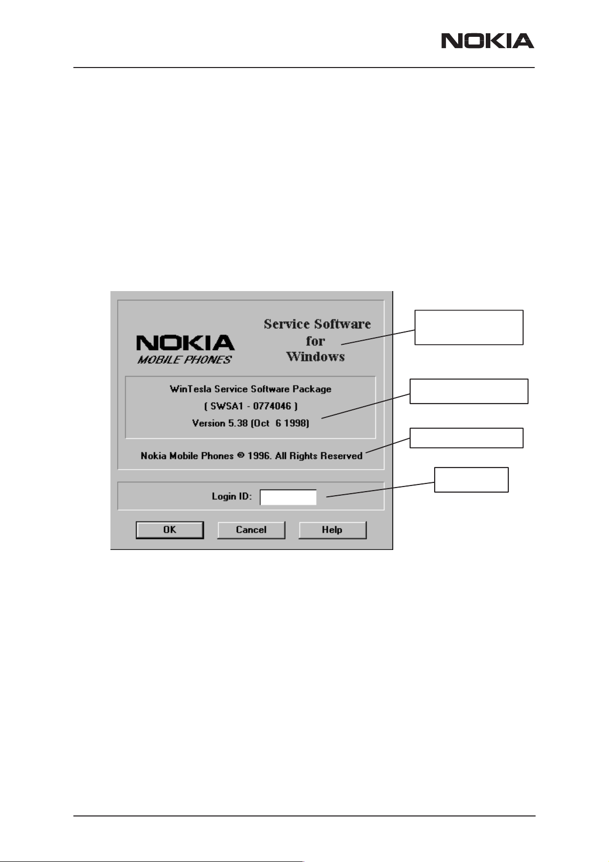
Login Dialog
When the Service Software application is invoked, by checking on the
Service Software icon, the Login dialog box will be displayed on the
screen.
Nokia logo and
application name
Nokia logo and application name bitmap (–)
Displays Nokia logo and name of the application.
Application version static text (–)
Contains the name and version of the application.
Copyright notice static text (–)
Copyright is informed as: “Nokia Mobile Phones (c) 1996. All
Rights Reserved”.
Application version
Copyright version
Login box
Page 10
Login Box edit box (–)
The user Login ID edit box, where the user enters his faultlog
user name. (See Faultlog User Guide)
OK button (default key)
The user name is stored in memory and the dialog box is
closed. When the dialog box is closed, the application starts.
Nokia Mobile Phones Ltd.
Issue 1 12/1999
Page 11

PAMS Technical Documentation
Cancel button (ESC)
The Dialog box is closed and application is started, but the
Faultlog feature is disabled.
Help button (F1)
Activates the Windows Help application and displays context
sensitive Help.
Main Window
Title bar
NSM–2
Service Software Instructions
The
title bar
A title bar contains the following elements:
• Application Control–menu button
• Maximise button
• Minimise button
• Name of the application
• Restore button
The properties of these elements and their usage is described in Ref 3–
Microsoft Windows Version 3.1 Users Guide chapter one (Windows Basics) and chapter two (Application Basics).
Menu bar
menu bar
The
tions. The menu bar is a dynamic element and is dependent on the
dongle type fitted, and whether a phone is connected.
Underlined characters in menu names and options indicates that the
menu selection can be done by pressing
tions can also be selected by activating menu bar with
key ) and using arrow–keys to highlight the desired menu. In that case,
selection is done by pressing
is located at the top of the window.
is below the title bar and contains all available menu selec-
Enter
Alt+ underlined character
Alt
– key ( or
.
. Op-
F10
Menus can also be selected by using the mouse as described in Ref
3–Microsoft Windows Version 3.1 Users Guide
Status bar
The
window. The status bar contains information about the menu selections
and events.
The left area of the status bar describes the actions of menu items as the
user uses the arrow keys to navigate through menus.
Issue 1 12/1999
status bar
is displayed at the bottom of the Service Software main
Nokia Mobile Phones Ltd.
Page 11
Page 12

NSM–2
Service Software Instructions
The status bar texts are explained in detailed in each of command’s description.
The right areas of the status bar indicate which of the following keys are
latched down:
Indicator Description
USER Entered Login ID.
CAP The Caps Lock key is latched down.
NUM The Num Lock key is latched down.
SCRL The Scroll Lock key is latched down.
Tool bar
The
tool bar
this document.
is NOT defined and will not be implemented until specified by
PAMS Technical Documentation
Page 12
Nokia Mobile Phones Ltd.
Issue 1 12/1999
Page 13
PAMS Technical Documentation
Menu Bar
The Service Software package will have two menu bar configurations.
The first, is an abbreviated version that contains the minimum number of
menus that allows package configurations when a phone is NOT connected. The second is described below:
The menu bar MUST only contain the follow menus for the Service Software package when a phone is connected:
roduct*
• P
• C
onfigure*
uning
• T
• Te
sting
oftware
• S
ealer
• D
NSM–2
Service Software Instructions
Product
iew
• V
• H
elp*
* – always displayed, even if no phone is connected.
A menu is broken down into sections that are indicated with menu separa-
tors. Each sections identifies a logical difference from itself and other sections, i.e. between transmitter and receiver. Any items that are required to be
added to a menu lists will be added on the bottom of the appropriate menu
section list. If a new item is to be added which is common to two or more
phone types, then that menu item will become a common menu item.
The menu lists will use the Microsoft [...] symbol after an item name to indicate that selecting that item will NOT initiate an operation immediately,
i.e. a dialog box will be displayed for the user to select options or type in
data and press the OK button before the operation is performed.
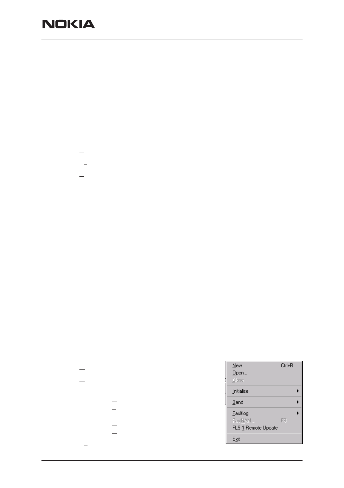
The Product menu contains at least the following menu items:
ew Ctrl+R
• N
pen...
• O
• C
lose
nitialize
• I
•Faultlog
it Alt+F4
• Ex
Issue 1 12/1999
• Normal Mode F5
ocal Mode Shift+F5
• L
• Activate Faultlog... F9
dit Faultlog...
• E
Nokia Mobile Phones Ltd.
Page 13
Page 14
NSM–2
Service Software Instructions
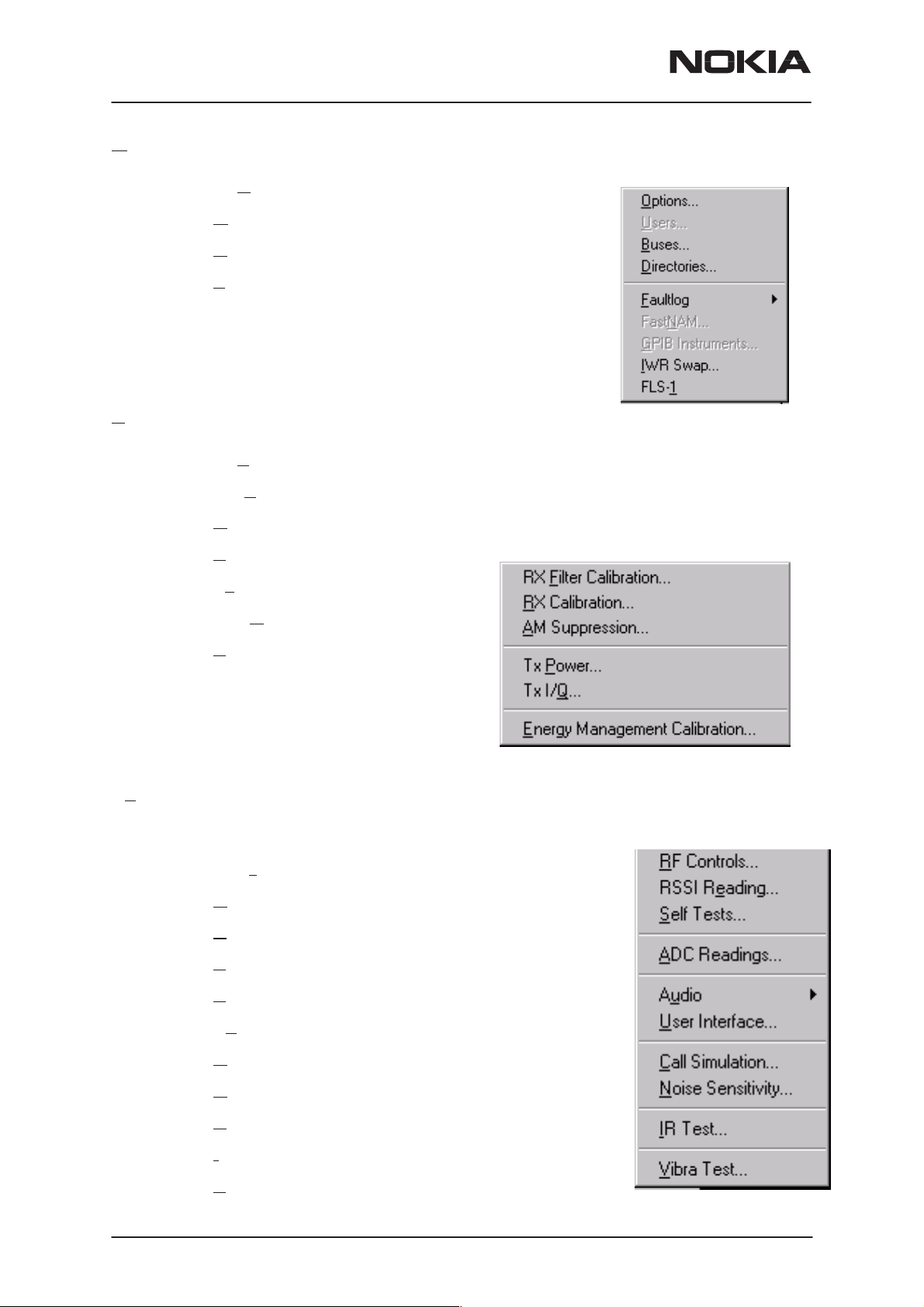
Configure
The Configure menu contains at least the following items:
• Options...
irectories...
• D
• Faultlog...
• Phone Type Specific configuration items
(where applicable)
Tuning
The Tuning menu contains at least the following menu sections:
• RX Filter Calibration...
PAMS Technical Documentation
Testing
• RX Calibration...
• AM Suppression...
• Tx Power...
• Tx I/Q
• Energy Management Calibration...
The Testing menu contains at least the following sections:
• RF Controls...
• RSSI Reading ...
• S
...
elf Tests
Page 14
• ADC Readings
• Au
dio
• User Interface
• Call Simulation
• Noise Sensitivity...
R Test
• I
• Vibra Test...
Nokia Mobile Phones Ltd.
Issue 1 12/1999
Page 15
PAMS Technical Documentation
Software
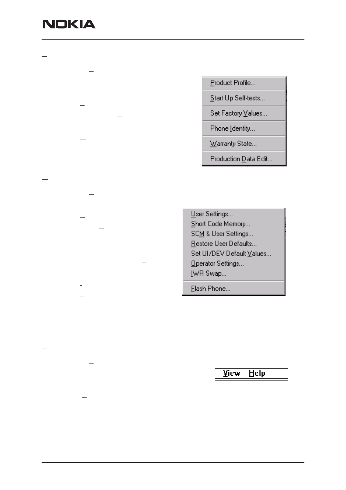
The Software menu contains at least the following menu sections:
• P
roduct Profile...
• S
tart Up Self–tests...
NSM–2
Service Software Instructions
Dealer
• Set Factory V
• Phone I
• W
arranty State...
• P
roduction Data Edit...
The Dealer menu contains at least the following menu sections:
• U
ser Settings...
• Short C
• SCM
• Restore User Defaults...
• Set UI/DEV Default V
• O
perators Settings...
dentity...
ode Memory...
& User settings ...
alues
alues ...
View
• I
WR Swap...
• F
lash Phone...
The View menu contains at least the following sections:
• Q
uick/RF Info...
• P
hone Information...
Issue 1 12/1999
Nokia Mobile Phones Ltd.
Page 15
Page 16
NSM–2
Service Software Instructions
Phone Identity Window
The Phone Identity window should contain, as a minimum, the following
data:
• Software Version(s)
• Hardware Version(s)
• Serial Number(s)
• Product Code
This window will only be used as a display window and therefore will not
allow editing of the displayed data. This window will not contain any controls other than a scroll bar.
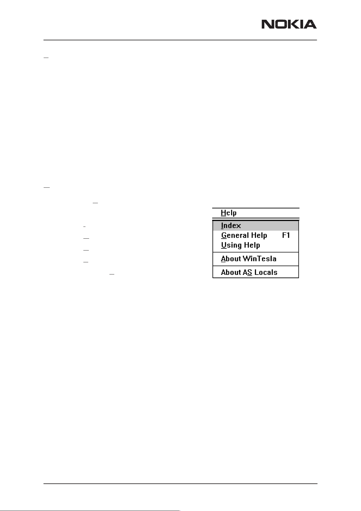
Help
The Help menu contains at least the following menu items:
PAMS Technical Documentation
• I
ndex
eneral Help
• G
• U
sing Help
• A
bout WinTesla
• About AS
Locals
Page 16
Nokia Mobile Phones Ltd.
Issue 1 12/1999
Page 17

PAMS Technical Documentation
Mouse Cursors
The standards Windows pointer will be used as the mouse cursor.
During time consuming tasks e.g. communication to phone, an hour glass
will be shown informing the user that a task is in progress. The application
uses the hour glass cursor to inform user that the application has taken
the control and any actions from user will be ignored.
When a function is initiated, the hour glass will be displayed and when the
function has finished the mouse pointer will return to normal.
Reserved Keys
The following Hot keys and Short Cut keys are reserved either as Microsoft standard keys or as part of the Common Look and Feel specified by
this document.
Short Cut Function Keys
NSM–2
Service Software Instructions
Key Description Defined
by
F1 Context Sensitive Help Microsoft
F5 Normal Mode NMP
Shift+F5 Local Mode NMP
F9 Activate Faultlog NMP
F10 Goto Menu Bar Microsoft
Ctrl+F4 Close Active Window Microsoft
Alt Hot Keys
Key Description Defined
by
Alt+F4 Exit Active Application Microsoft
Alt+H Help Microsoft
Ctrl Hot Keys
Key Description Defined
by
Ctrl+N File – New Microsoft
Ctrl+O F
Ctrl+P F
Ctrl+R Product – New NMP
Issue 1 12/1999
ile – Open Microsoft
ile – Print Microsoft
Nokia Mobile Phones Ltd.
Page 17
Page 18

NSM–2
Service Software Instructions
Shift Hot Keys
Key Description Defined
by
Shift+F5 Local Mode NMP
Key Strokes
Key Description Defined
by
Alt+P Product Menu NMP
PAMS Technical Documentation
Alt+P,N N
Alt+P,O Open NMP
Alt+P,C C
Alt+P,I Initialize Pop–up NMP
Alt+P,I,N N
Alt+P,I,L Local Mode NMP
Alt+P,F Faultlog Pop–up NMP
Alt+P,F,A A
Alt+P,F,E E
Alt+P,X Exit Application NMP
Alt+C Configure NMP
Alt+C,O O
Alt+C,D Directories NMP
Alt+C,F F
Alt+C,G GPIB instruments (disabled) NMP
ew NMP
lose NMP
ormal Mode NMP
ctivate Faultlog NMP
dit Faultlog NMP
ption NMP
aultlog NMP
Page 18
Alt+T T
Alt+T,R RX Calibration NMP
Alt+T,X Tx Power NMP
Alt+T,Q Tx I/Q
Alt+T,E E
Alt+E Testing Menu NMP
Alt+E,F RF Controls NMP
Alt+E,R R
Alt+E,S Self Tests NMP
Alt+E,A ADC Readings NMP
Alt+E,U Au
Nokia Mobile Phones Ltd.
uning Menu NMP
NMP
anergy Management calibration NMP
SSI Reading NMP
dio NMP
Issue 1 12/1999
Page 19

PAMS Technical Documentation
Alt+E,U,I Audio Internal NMP
NSM–2
Service Software Instructions
Alt+E,U,E Audio E
Alt+E,U User Interface NMP
Alt+E,C C
Alt+E,N N
Alt+E,I I
Alt+S S
Alt+S,P P
Alt+S,S S
Alt+S,V Set Default V
Alt+S,I Phone I
Alt+S,P P
Alt+S,F F
Alt+D D
Alt+D,U U
Alt+D,S S
all Simulation NMP
oise Sensitivity NMP
R Test NMP
oftware Menu NMP
roduct Profile NMP
tart–up Self Tests NMP
roduction Data Edit NMP
lash Phone NMP
ealer Menu NMP
ser Settings NMP
hort Code Memory NMP
xternal NMP
alues NMP
dentity NMP
Alt+D,M SCM
Alt+D,V Set UI/DEV Default V
Alt+V V
Alt+V,Q Q
Alt+V,P P
Alt+H H
Alt+H,I I
Alt+H,G G
Alt+H,U U
Alt+H,A A
Alt+H,S About AS
& User Settings NMP
iew Menu NMP
uick/RF Info NMP
hone Identity NMP
elp Menu Microsoft
ndex Microsoft
eneral Help Microsoft
sing Help Microsoft
bout WinTesla NMP
Locals NMP
alues NMP
Issue 1 12/1999
Nokia Mobile Phones Ltd.
Page 19
Page 20

NSM–2
Service Software Instructions
Help Functions
The Help User Interface will be the standard Windows help tool called
WinHelp.
The context sensitive help is activated with F1–key. Help contains also
Using Help which describes how to use help facility. Refer to the Windows
manual for detailed description on the Windows Help.
Dialog boxes
The Service Software application uses many different dialog boxes. Dialog boxes are used to display data and prompt the user for input.
Dialog boxes are opened from menus or with shortcut keys. Dialog boxes
have different properties but some features are common.
All service dialog boxes must be modal, that is, the user will not be able to
start another operation without first closing the present dialog box.
All dialog boxes will contain the following entities:
PAMS Technical Documentation
– Help button
– Title bar
– At least one button other than Help
– Application Control–menu Button
Common Dialog boxes
This sections describes the common dialog boxes used in the Service
Software package, and the context in which they will be used.
Note Message Box
When the user has made an illegal selection, a
will be opened and message text is displayed. The message box is also
opened when the program has some information for the user. The size of
the dialog box may vary. An information dialog box is recognized by the
!–icon.
The dialog box will also contain an OK button and a Help button.
note message box
dialog
OK button (default key):
Help button (Alt+H):
Query Message Box
Confirmations and questions are asked in
dialog box is recognized by the ?–icon.
Page 20
Acknowledge displayed information and continue. The dialog
box is closed after selection.
Opens context sensitive help as F1–key does.
Nokia Mobile Phones Ltd.
a query message box
Issue 1 12/1999
. A query
Page 21

PAMS Technical Documentation
The dialog box will also contain a Yes button, a No button, and a Help
button.
Yes button (Alt+Y or Y) (default key):
Accepts confirmation or question.
No button (Alt+N or N):
Denies confirmation or question.
Help button (Alt+H):
Opens context sensitive help as F1–key does.
The buttons may also be OK and Cancel. The operation of these buttons
are the same as in the Note dialog box.
Error Message Box
NSM–2
Service Software Instructions
Error message dialog boxes use the Stop–icon. When a “Stop”–dialog
box is shown, the current operation is terminated.
The dialog box has a description about the failed operation and reason.
Pressing F1 (Help) application opens the appropriate help topic that gives
information about recommended actions.
The dialog box will also contain an OK button and a Help button.
OK button (default key):
Acknowledges displayed information and terminate current operation. The dialog box is closed after selection.
Help button (Alt+H):
Open context sensitive help as F1–key does.
Issue 1 12/1999
Nokia Mobile Phones Ltd.
Page 21
Page 22

NSM–2
Service Software Instructions
Custom Dialog boxes
All custom dialog boxes will contain the predefined buttons as defined below in the section –
require additional button types, but the addition of these non–standard
buttons should be carefully considered to minimise any inconsistencies
between implementations.
The buttons will be positioned down the right–hand side of the dialog
boxes. The default action will be OK, except where that default action
could result in an irretrievable failure.
All tuning dialogs that contain tuning results, will display the old tuned
data read from the phone before the tuning was performed, as well as the
newly tuned data.
List boxes will be used to display lists of data, such as tuning data, test
results etc.
The use of Radio buttons should be limited and carefully considered. The
use of radio buttons defines the number of possible choices available to
the user, which may be acceptable for one project, but not for another.
Buttons.
PAMS Technical Documentation
However, it is recognised that features may
Buttons
All buttons must be the Microsoft style of buttons.
In general, the default button will be the action button, the Close button or
the Yes button, but this will depend on the context of the dialog box that
the button is associated with.
(action) button:
Accepts and validates entered settings and values and closes
the dialog. If the values have not been changed, then no action
will be taken. The status bar will reflect the status. The user
should only be queried, if the settings or values accepted will
over–write data that CAN NOT be reproduced.
A greyed OK button indicates that settings selected by the user
are not acceptable.
Close button:
Closes the current dialog box. Does not send or store anything
and closes the dialog. The Close button is only used for dialogs that do not set or change any data.
Cancel button (Esc):
Page 22
Cancel operation. Does not send or store anything and closes
the dialog box.
A greyed Cancel button indicates that it is not possible to quit
from this dialog box.
Yes button (ALT+Y or Y):
Nokia Mobile Phones Ltd.
Issue 1 12/1999
Page 23

PAMS Technical Documentation
Replies Yes to a question asked of the user.
No button (ALT+N or N):
Replies No to a question asked of the user.
Help button (ALT+H):
Opens context sensitive help as F1–key does.
Reporting Status
The status bar will be used to report the present status to the user. When
a feature is initiated, the status bar will be updated with a brief description
of the function. The status bar will also be updated at key points in a time
consuming function.
If an error is to be reported to the user, it will be displayed in the status
bar as well as displayed in a common error dialog box. This will mean the
user is not delayed from progressing on to the next operation unless an
error occurs, in which case, the user will have to acknowledge the error
by pressing the OK button.
NSM–2
Service Software Instructions
Issue 1 12/1999
Nokia Mobile Phones Ltd.
Page 23
Page 24

NSM–2
Service Software Instructions
NSM–2 FEATURES
Menu bar
After Sales SW’s menus follow the menu structure specified in WinTesla
User Interface Specification. This specification will describe functionality
that differs from WinTesla specification.
Product
New command
Activation Status Bar Text
Alt, P, N Rescan a new phone
PAMS Technical Documentation
Ctrl+R
If phone is changed (with same phone type only serial number is
changed) phone will be initialised to local/normal mode (selected in TESLA.INI). If phone is changed to different phone type the current DLLs are
unloaded and new ones are loaded for that phone.
If the Quick/RF Info view is open, window will be automatically updated.
If Phone Information view is open, window will be automatically updated.
NOTE: When different type of phone is changed user should select Product/New, so that application recognises phone type change and loads correct menu.
pen... command
O
Activation Status Bar Text
Alt, P, O Force load phone specific functionality
Phone is set to local/normal mode. If no phone is found, connection para-
meters (from Configure/Busses) are displayed to user and application
asks from user does (s)he want to use that connection to flash a phone. If
user selects Yes, current connection is used and flash only menu is
loaded. If user selects No, application tries next connection, if there is
one.
nitialise... command
I
Activation Status Bar Text
Alt, P, I
Opens a submenu which contains the following options:
Page 24
Nokia Mobile Phones Ltd.
Issue 1 12/1999
Page 25

PAMS Technical Documentation
Normal Mode
Activation Status Bar Text
Alt, P, I, N Initialises phone to normal mode
F5
When normal mode has been activated or program has been started,
self–test results will be asked from MCU. If fault was found in the tests, an
error message is shown. If normal mode has been set successfully (no
self test error has been found), and paging listening has been started, the
used AFC value is requested from MS.
Initialisation routine checks phone’s cellular type and if unsupported
phone is detected, application unloads the DLLs.
The After Sales SW sets automatically the MS state to normal mode
when needed.
If phone identification view is open, window will be automatically updated.
Also if RF Information Window is open it will be updated to quick info
view.
NSM–2
Service Software Instructions
NOTE: When phone is changed to but phone type does not change, user
may select Product/Initialise/Normal Mode instead of Product/New.
Local Mode
Activation Status Bar Text
Alt, P, I, L Initialises phone to local mode
Shift+F5
Selection will change the MS state to
Testing or Tuning menus, the After Sales SW software will change automatically the MS state to local.
The After Sales SW sets automatically the MS state to normal mode
when needed.
Also if quick info view is open it will be updated to RF Information view.
and... command
B
This menu selection is for dual band phones.
Activation Status Bar Text
local
. When user selects item from
Alt, P, B Opens a submenu which contains following options:
Issue 1 12/1999
Nokia Mobile Phones Ltd.
Page 25
Page 26

NSM–2
Service Software Instructions
GSM
Activation Status Bar Text
Alt, P, B, G Set phone to GSM band.
CN
P
Activation Status Bar Text
Alt, P, B, P Set phone to PCN (GSM1800) band.
PAMS Technical Documentation
Page 26
Nokia Mobile Phones Ltd.
Issue 1 12/1999
Page 27
PAMS Technical Documentation
Tuning
The tuning menu offers functions for ME adjustments.
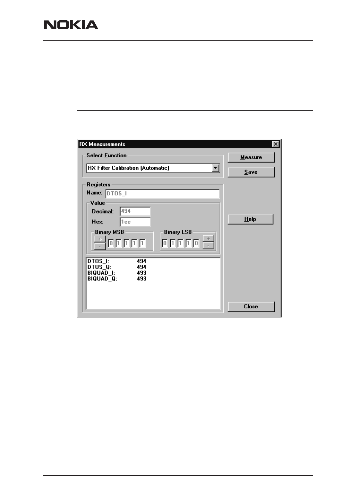
RX Filter Calibration... command
Activation Status Bar Text
Alt, T, M Open RX Measurements dialog box
Starts RX Filter Calibration tuning for the phone.
NSM–2
Service Software Instructions
Dialog mode: Modal
RX Measurements dialog has the following items:
Select Function listbox:
Value group:
Measure button:
Issue 1 12/1999
Shows list of automatic selections. When selection is made values are loaded from phone.
This group has several items. At the bottom there is a list of
registers and values they currently have. Double clicking a record from the list will bring it’s name to the name edit box. The
value is shown in the three different format decimal, hexadecimal and binary. All these controls display the same value and
changing one causes changes to others too.
This button activates the measurement.
Nokia Mobile Phones Ltd.
Page 27
Page 28

NSM–2
Service Software Instructions
Save button:
This saves values to the phone.
Close button:
This button closes the dialog without saving anything.
Help button:
This button opens help.
PAMS Technical Documentation
Page 28
Nokia Mobile Phones Ltd.
Issue 1 12/1999
Page 29
PAMS Technical Documentation
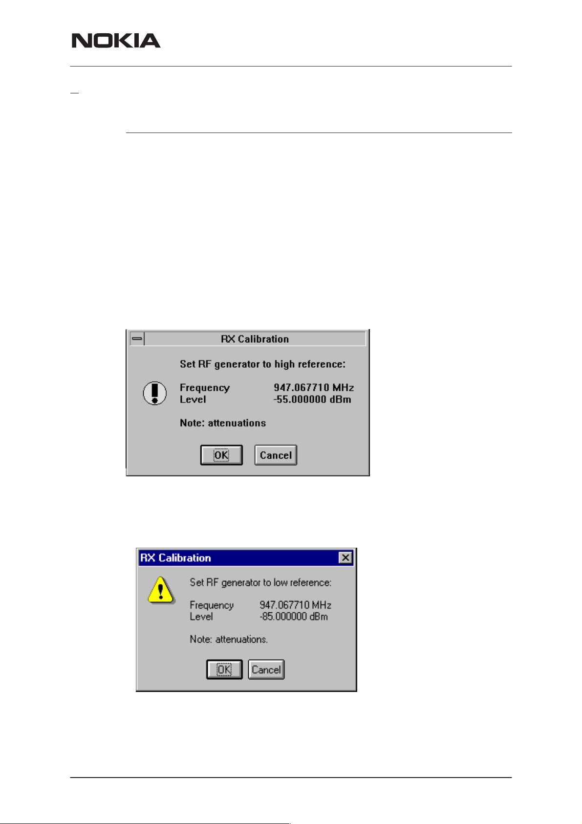
RX Calibration... command
Activation Status Bar Text
Alt, T, R Open RX Calibration dialog box
Starts RX calibration.
The next automatic selections are made when this tuning function is acti-
vated:
• Phone is set to local mode
• Update RF information window
The measurement is started automatically when RX calibration is entered.
The measurement is done in five steps:
1. User is requested to put signal generator to high input level (read from
.INI file).
NSM–2
Service Software Instructions
2. Measurement with high input level is executed
3. User is requested to put signal generator to low input level (read from
.INI file).
4. Measurement with low input level is executed
5. The RX Calibration dialog will be updated when previous steps are
done.
Issue 1 12/1999
Nokia Mobile Phones Ltd.
Page 29
Page 30

NSM–2
Service Software Instructions
PAMS Technical Documentation
Dialog mode: modal
RX Calibration dialog has the following items:
AFC information box:
Shows AFC init value, AFC slope and PSW slope values.
AGC List box (ALT+A):
AGC, DAC, Voltage.
Repeat button (ALT+R):
Measurement can be started again by pressing this button.
Save button (ALT+S):
Dialog is closed and tuning
Cancel button (ESC):
Dialog is closed and tuning
When calibration is ended, the DAC value checking is made and if it is not
successful, error message is shown.
When exit is made, the next selections are set to the values which were
selected before this adjustment.
Operation Mode
is saved
is not saved
to phone.
to phone.
Page 30
Update RF Information window
The exit and the use of AGC–control values is done same way as exit
from power level tuning and power coefficient use:
Nokia Mobile Phones Ltd.
Issue 1 12/1999
Page 31

PAMS Technical Documentation
Dual Band Specific Features
When tuning dual band phones both bands must be tuned. Tuning is always started in GSM band. If current band is PCN, user is asked to confirm band change or cancel tuning with following dialog.
If PCN band was selected, when tuning was selected, tuning is automatically continued in PCN band, after saving tuning values in GSM band. If
tuning was started in GSM band, user is asked to continue tuning in PCN
band.
If user wants to cancel tuning without saving values in PCN band, there is
two confirmation dialogs to make sure that user does not accidentally
cancel tuning in PCN band.
NSM–2
Service Software Instructions
To cancel tuning answer No to first dialog and Yes to second dialog.
When dialog is closed original band is selected.
Issue 1 12/1999
Nokia Mobile Phones Ltd.
Page 31
Page 32

NSM–2
Service Software Instructions
RX AM Suppression... command
Activation Status Bar Text
Alt, T, M, A Open RX Measurements dialog box
Starts RX AM Suppression tuning for the phone.
PAMS Technical Documentation
Dialog mode: Modal
RX Measurements dialog has the following items:
Select Function listbox:
Shows list of automatic selections. When selection is made values are loaded from phone.
Value group:
This group has several items. At the bottom there is a list of
registers and values they currently have. Double clicking a record from the list will bring it’s name to the name edit box. The
value is shown in the three different format decimal, hexadecimal and binary. All these controls display the same value and
changing one causes changes to others too. Last line shows
RSSI value.
Measure button:
This button causes the measurement to be done. When selected following dialog is shown.
Page 32
Nokia Mobile Phones Ltd.
Issue 1 12/1999
Page 33

PAMS Technical Documentation
Save button:
This saves the values to the phone.
Close button:
This button closes the dialog withour saving anything.
Help button:
This button opens help.
NSM–2
Service Software Instructions
Issue 1 12/1999
Nokia Mobile Phones Ltd.
Page 33
Page 34

NSM–2
Service Software Instructions
Tx Power... command
Activation Status Bar Text
Alt, T, X Open TX Power Tuning dialog box
Starts TX power tuning.
When user has PKD–1 dongle in place, then tuning is started automati-
cally with EEPROM values. If values read from EEPROM are not valid
then user is able to start the tuning with factory values. There is a notification shown if this happens. With other dongles user is first requested to
select with which values tuning is started in Start Tuning dialog.
PAMS Technical Documentation
Start Tuning dialog has following items:
Start Tuning With list box (ALT+S):
1 EEPROM Values
Tuning values are load from ME’s EEPROM.
2 Factory Default Values
Tuning values are load from ME’s flash.
3 Current Values in PC memory
Tuning values are load from program’s internal memory.
The next automatic selections are made when this tuning function is activated:
the BASE power level is selected
Operation mode = TX pulsed
Page 34
Nokia Mobile Phones Ltd.
Issue 1 12/1999
Page 35

PAMS Technical Documentation
The TX Power Tuning dialog will be activated automatically after value
selection.
GSM900 TX Power Tuning dialog:
NSM–2
Service Software Instructions
GSM1800 TX Power Tuning dialog:
Dialog mode: modal
TX Power Tuning dialog has following items:
Level, Coefficient and Targets list box (ALT+L):
Issue 1 12/1999
Nokia Mobile Phones Ltd.
Page 35
Page 36

NSM–2
Service Software Instructions
The power is presented in GSM or PCN values. The base power is selected automatically when the dialog is opened. The
test value is not saved to the EEPROM. The test value can be
changed during tuning as other power coefficients and the program remembers its value when tuning function is activated
later again.
If there is more power levels in the phone that can fit into window the window is scrollable. When phone is initialised the program asks the number of power levels used in the phone.
Only three power coefficients (highest, third smallest and lowest) are needed to tune (left justified Coefficients) and the rest
of them are calculated.
The tuning position is highlighted and can be tuned with +/–
keys or left/right cursor keys.
Calculate button (ALT+C):
The calculation is activated with this button. The power coefficients which are calculated from the tuned coefficients are displayed on the different columns than the others. All values can
be tuned if needed. When Base level calculation is checked,
base level is calculatede and new base level target to list box is
updated.
PAMS Technical Documentation
Base level calculation check box:
If this box is checked the base level is calculated.
Base offset edit box:
This edit box shows the base offset value that user can
change. The base level calculation check box must be checked
before this value is used. After this value is changed user must
do the calculation.
NOTE: Do not use Enter–button to accept this value.
+/– buttons (+/– and left/right cursor keys):
+ and – buttons will cause power changing by 0.25dB steps.
When these keys are used the coefficient value is updated on
the tuning window.
Save button (ENTER):
Dialog is closed and tuned values are
offset is saved to TESLA.INI.
Cancel button (ESC):
Dialog is closed and tuning
When selections are used, the power value checking is made and if it is
not successful, error message is shown. The test checks that all power
coefficients are in descending order (same order than power levels).
is not saved
saved
to phone. Base
to phone.
Page 36
If the power tuning function is ended and EEPROM values are not received or EEPROM fault is noticed, an error message is shown.
Nokia Mobile Phones Ltd.
Issue 1 12/1999
Page 37

PAMS Technical Documentation
When all power coefficients have such values that they don’t cause any
error messages, they can be saved. The last used tuning power is in use
after exit.
The next automatic selection is made when this tuning function is ended:
Operation Mode = RX pulsed
When dialog is closed original band is selected.
NSM–2
Service Software Instructions
Issue 1 12/1999
Nokia Mobile Phones Ltd.
Page 37
Page 38

NSM–2
Service Software Instructions
Tx I/Q... command
Activation Status Bar Text
Alt, T,Q Open TX I/Q Tuning dialog box
This function is used for tuning TX I and Q branch DC offset, amplitude
difference and phase difference.
If user has PKD–1 dongle and other than NSM–X phone, then tuning is
started automatically with EEPROM values. When using other dongles
this selection opens same Start Tuning dialog as with TX Power Tuning.
The next automatic selections are made when this function is activated:
Operation Mode = TX pulsed
Update RF Information window
The TX I/Q Tuning dialog is opened.
PAMS Technical Documentation
Dialog mode: modal
TX I/Q Tuning has following items:
Tune TX I
Tune TX Q
Tune A
Tune P
DC Offset scroll bar (ALT+I):
The DC Offset is shown as percents (%) from the ± maximum
value. 0% means that there is no DC. The value range is
–100%...100%. The value is rounded to the nearest integer
value.
DC Offset scroll bar (ALT+Q):
The operation of this function is the same as one above, except with this selection the Q branch DC Offset is tuned. The
value range is –100%...100%. The value is rounded to the
nearest integer value.
mplitude Difference scroll bar (ALT+A):
When this selection is made user can increase or decrease the
amplitude difference within 0.1 dB steps. The value range is
–1...1.
hase Difference scroll bar (ALT+P):
When this selection is made user can increase or decrease the
phase difference within 0.5° steps. The current phase differ-
Page 38
Nokia Mobile Phones Ltd.
Issue 1 12/1999
Page 39

PAMS Technical Documentation
ence is shown on the tuning window with numbers and bar figure. The value range is 85...95.
Save/OK button (ENTER):
NSM–2
Service Software Instructions
Dialog is closed and tuning
NSM–X phones in GSM band button values are only saved to
PC memory and those values may be used when tuning is
started in PCN band.
Cancel button (ESC):
Dialog is closed and tuning
After each value change the new value is sent to the phone.
The next automatic selection is made when TX I / Q tuning function is en-
ded:
Operation Mode = RX pulsed
Update RF Information window
NOTE: Tuning needs to be done for GSM900 and GSM1800 bands sepa-
rately.
is saved
to phone. When tuning
is not saved
to phone.
Issue 1 12/1999
Nokia Mobile Phones Ltd.
Page 39
Page 40

NSM–2
Service Software Instructions
Energy Management Calibration... command
Activation Status Bar Text
Alt, T,E Calibrate Battery Voltage
This function is for battery a/d and charge current tunings.
Before battery a/d tuning is started a voltage setting request is shown to
user (Set supply voltage to 10,5 V). Service Battery is in this case JBU–6.
NOTE: Set DC Supply Mode in JBU–6 in FLA–5 (FLA–5/7) position!
PAMS Technical Documentation
When external power is connected and user selects Yes to continue, the
application displays the Energy Management Calibration dialog box:
Page 40
Dialog mode: modal
Energy Management Calibration dialog has following items:
Nokia Mobile Phones Ltd.
Issue 1 12/1999
Page 41

PAMS Technical Documentation
Settings group box:
Contains EM calibration setting checkboxes:
1. Run battery & charger default values checkbox (ALT+1):
Runs battery & charger default values to phone when selected
2. Battery voltage checkbox (ALT+2):
Calibrates battery voltage A/D value.
3. Charger voltage checkbox (ALT+3):
Calibrates charge voltage A/D value.
4. Battery size checkbox (ALT+4):
Calibrates battery size A/D value.
5. Battery temperature checkbox (ALT+5):
Calibrates battery temperature A/D value.
6. Charge current checkbox (ALT+6):
NSM–2
Service Software Instructions
Calibrates charging current.
Save without confirmation checkbox (ALT+S):
When selected, all selected calibrations are saved to phone
without confirmation, otherwise user must confirm every A/D
value saved to phone. Calibration info is automatically scrolled
during confirmation.
Calibration info listbox (ALT+S)
Shows information about current calibrations.
Run button (ENTER):
All selected settings are executed.
Close button (ESC):
Dialog is closed.
Help button (ALT+H):
Context sensitive help.
After battery a/d tunings a voltage setting request is shown to user (Set
supply voltage to 8.0 V).
Issue 1 12/1999
Nokia Mobile Phones Ltd.
Page 41
Page 42

NSM–2
Service Software Instructions
Testing
The Testing sub menu offers functions for ME testing.
F Controls... command
R
Activation Status Bar Text
Alt, E,R Open RF Controls dialog box
This function is used for RF testing.
Command opens RF Controls dialog, which contains data for testing and
adjustments.
PAMS Technical Documentation
Page 42
Dialog mode: modal
RF Controls dialog has following items:
Active Unit group:
RX radio button (ALT+R):
When
The RX value is always given as default.
Note! Function is activated immediately, Apply is not needed.
TX radio button (ALT+T):
RX
is selected, the next functions are made:
Data transmission is deactivated
TX power is deactivated
If operation mode is continuous,
– AGC is controlled
– RX continuous mode channel is activated
RF Information window is updated
Nokia Mobile Phones Ltd.
Issue 1 12/1999
Page 43

PAMS Technical Documentation
When TX is selected, the next functions are made:
Data transmission is activated
If operation mode is continuous,
– Operation mode is set to burst
RF Information window is updated
Continuous mode radio button is disabled.
Note! Function is activated immediately, Apply is not needed.
Operation Mode group:
Continuous radio button (ALT+C):
NSM–2
Service Software Instructions
When
synthesiser is set to constant frequency
synthesiser channel number is as given with Continuous Mode
Channel selection
transmitter power is not connected
if Active Unit is RX, AGC is controlled
Note! Function is activated immediately, Apply is not needed.
Burst radio button (ALT+B):
When
synthesiser is controlled by using receiving/transmission/
measuring synthesiser control sequence
synthesiser channel numbers are as given with Channel/
Monitoring Channel selections
if Active Unit is TX, data (selected with TX Data Type) is sent
and the TX power is connected
Note! Function is activated immediately, Apply is not needed.
ata Type drop list (ALT+D):
TX D
continuous
burst
selection is used,
selection is used,
TX Power Level edit box (ALT+T):
Issue 1 12/1999
This list changes the transmission data type. List consists fol-
lowing options: 0, 1, Random and User. After Random data
selection 0 is used. If Operating Mode is
Type Random causes different data sending than in burst
mode. User data is defined in TESLA.INI file by the user
(open).
With this value is possible to change the transmission power.
The user can give the needed power value or select the test
value, which is tuned with TX power tuning function. The test
value is found at the end of the list.
OFF
TX Power have value
tive unit is RX. When the TX power is tuned with test value
(smallest value) the TX Power has value
Nokia Mobile Phones Ltd.
and is disabled (
continuous
greyed
TEST
, TX Data
) when ac-
.
Page 43
Page 44

NSM–2
Service Software Instructions
Channel edit box (ALT+H):
User can enter here channel number that is used for both
transmission and receiving. The frequency of the selected
channel is shown after selection.
Monitoring Channel edit box (ALT+M):
This field selects neighbour monitoring channel. The frequency
of the selected channel is shown after selection.
Continuous Mode Channel edit box (ALT+C):
To this edit box user can type continuous mode channel which
may have all channel numbers.
The used frequency depends on the Active Unit. If Active Unit
is RX, then RX frequency is used, else TX frequency. The fre-
quency of the selected channel is shown after selection.
Gain Step Value edit box (ALT+L):
This selection allows user to set up the receiver gain step in
continuous mode. There are nine (0...8) steps. In the burts
mode selection is automatic.
PAMS Technical Documentation
AFC edit box (ALT+F):
This selection allows user manually tune the 26 MHz clock.
Limits are –1023...–1024
Apply button (ALT+A):
Accepts entered values and validates them. After validation ap-
plication sends corresponding messages to ME. Closes dialog
and updates Info Window.
Note! Active Unit and Operation mode are not send with because they are
activated immediately.
Set Defaults button (ALT+S):
Sets current values as default Rf Controls values.
Get Defaults button (ALT+U):
Gets default Rf Controls values as current values.
The next automatic selection is made when Quick testing function is ended:
Active Unit = RX
Update RF Information window
The next table shows the dialog’s properties on different situations:
Page 44
ACTIVE UNIT = TX:
TX Data Type: Updated
AGC values: Greyed
Monitoring Channel: Greyed
OPERATION MODE = BURST:
TX Power Level: Updated
Nokia Mobile Phones Ltd.
Issue 1 12/1999
Page 45

PAMS Technical Documentation
Continuous Mode Channel: Greyed
Channel: Updated
OPERATION MODE = CONT.:
TX Power Level: OFF, Greyed
Continuous Mode Channel: Updated
Channel: Greyed
ACTIVE UNIT = RX:
TX Data Type: Greyed
TX Power Level: OFF, Greyed
OPERATION MODE = BURST:
AGC values: Greyed
Continuous Mode Channel: Greyed
Channel: Updated
NSM–2
Service Software Instructions
Monitoring Channel: Updated
OPERATION MODE = CONT:
AGC values: Updated
Continuous Mode Channel: Updated
Channel: Greyed
Monitoring Channel: Greyed
Issue 1 12/1999
Nokia Mobile Phones Ltd.
Page 45
Page 46

NSM–2
Service Software Instructions
RSSI Reading... command
Activation Status Bar Text
Alt, E,R Read continuously RSSI value
Command opens RSSI Reading dialog:
PAMS Technical Documentation
Dialog mode: modal
RSSI value is read continuously until user presses ESC–key or Close but-
ton to cancel reading.
RSSI Reading dialog has following items:
Close (ENTER) button:
Closes the RSSI Reading dialog. Does not send anything to
phone.
H
elp button:
Context sensitive help.
Page 46
Nokia Mobile Phones Ltd.
Issue 1 12/1999
Page 47

PAMS Technical Documentation
Self Tests... command
Activation Status Bar Text
Alt, E,S Open MCU Self–tests dialog box
Command is used for reading self test results and running self tests.
When the selection is made, the test result is read from ME. The test re-
sult will be shown to the user within MCU Self–test dialog.
NSM–2
Service Software Instructions
Dialog mode: modal
MCU Self–test dialog has following items:
Tests list box (ALT+T):
The field ”(p)” in the screen example means that the test is also
run in power up. The field “/s)” means that this test is select-
able one.
Test states are updated according to results received from the phone.
Possible test states will be one of the next:
Passed
Failed
No response
Not executed
Not valid
RUNNING....
Note that power–off test have no values, because if test has been
passed, power has been turned off. If power–off test fails a special error
Issue 1 12/1999
Nokia Mobile Phones Ltd.
Page 47
Page 48

NSM–2
Service Software Instructions
message window is shown. If no response is received to power off test
message in a few seconds, the user is informed by special info window,
where user is asked to turn the power on and then press the return key.
Note also that power–off test (if passed) turns power off and power
should be reconnected by using the phones keypad after the successful
test. After the power has been connected to phone, the normal start–up
routines are made and the self–test results are shown in the MCU self–
tests menu (i.e. all other than power–up self–tests are in
state after the power–up routines).
Run button (ALT+R):
User can select desired test from list and hit Run button. When
user selects test to be run the text
state field and test is run. When results are received the test
state field is updated according to the result.
PAMS Technical Documentation
Not executed
RUNNING...
is shown in test
If no response was received in the defined time, a
sage box
sponse
Run A
Supported Self Tests
1 MCU ROM Checksum................
2 MCU RAM Interface...............
3 MCU RAM Component...............
4 MCU EEPROM Interface............
5 MCU EEPROM Component............
6 RTC Battery.....................
7 CCONT Interface.................
ll button (ALT+A):
User can run all listed tests. The text
test state field and test is run. When results are received the
test state field is updated according to the result. When state
field is updated application moves to next test and repeats pre-
vious cycle. Phone is set to local mode if it is not already there.
will be shown and the test state is changed to
. Phone is set to local mode if it is not already.
RUNNING...
error mes-
No re-
is shown in
Page 48
8 A/D Converter...................
9 SW Reset........................
A Power Off.......................
B Security Data...................
C EEPROM Tune Checksum............
D PPM Checksum....................
E MCU Download DSP................
F DSP Alive.......................
G COBBA Serial.......................
H COBBA Parallel.....................
Nokia Mobile Phones Ltd.
Issue 1 12/1999
Page 49

PAMS Technical Documentation
I EEPROM Sec Checksum................
J PPM Validity....................
K Warranty State....................
L SW Version....................
NSM–2
Service Software Instructions
Issue 1 12/1999
Nokia Mobile Phones Ltd.
Page 49
Page 50

NSM–2
Service Software Instructions
ADC Readings... command
Activation Status Bar Text
Alt, E,A Open ADC Readings dialog box.
Command is used to read and show A/D values from phone.
Command opens ADC Readings dialog.
PAMS Technical Documentation
Dialog mode: modal
ADC Readings dialog has static text field where measurements are up-
dated to window every one second.
ADC Readings dialog has following items:
Close (ENTER) button:
Closes the ADC Readings dialog. Does not send anything to
phone.
Help button:
Context sensitive help.
A/D Readings:
Following a/d readings are measured:
Battery Voltage.........:
Battery Temperature.....:
Charge Voltage..........:
Charge Current..........:
Battery Type............:
Page 50
Acessory Detection......:
Hook....................:
RSSI....................:
VCXO Temperature........:
Nokia Mobile Phones Ltd.
Issue 1 12/1999
Page 51

PAMS Technical Documentation
Audio... command
Activation Status Bar Text
Alt, E,U
Opens a submenu which contains following options:
Internal Audio Loops
Activation Status Bar Text
Alt, E,U,I Open Internal Audio loops dialog box.
Command is used for making internal audio loop tests in Internal Audio
Loops dialog.
NSM–2
Service Software Instructions
Dialog mode: modal
Internal Audio Loops dialog has following items:
Buzzer Volume group:
Volume On radio button (ALT+V):
Volume O
Level drop down list (ALT+L):
Freq
Issue 1 12/1999
Next three different values can be selected for Buzzer volume:
Turns buzzer on.
ff radio button (ALT+O):
Turns buzzer off.
Sets level of a buzzer. Allowed range 0...127
uency radio button (ALT+Q):
Nokia Mobile Phones Ltd.
Page 51
Page 52

NSM–2
Service Software Instructions
Turns buzzer off.
Internal Audio Loop group:
Input group:
Next two different values can be selected for input:
Internal radio button (ALT+I):
Turns internal input.
External radio button (ALT+I):
Turns external input.
Hea
dset radio button (ALT+A):
Turns headset input. Note: If Output is not Headset, loop is
turned off.
Output group:
Next two different values can be selected for output:
Int
ernal radio button (ALT+T):
PAMS Technical Documentation
Turns internal output.
External radio button (ALT+X):
Turns external output.
Head
set radio button (ALT+D):
Turns headset output. Note: If Input is not Headset, loop is
turned off.
Loop group:
Next two different values can be selected for loop:
Off radio button (ALT+F):
Turns audio loop off.
On
radio button (ALT+N):
Turns audio loop on.
When dialog is closed with the Buzzer Volume is switched always off.
Also internal audio loop is turned off.
Page 52
Nokia Mobile Phones Ltd.
Issue 1 12/1999
Page 53

PAMS Technical Documentation
User Interface... command
Activation Status Bar Text
Alt, E,U Open User Interface Tests dialog box
Command is used for making display tests in Display Tests dialog.
Dialog mode: modal
Display Tests dialog has following items:
1. Test Pattern radio button (ALT+1):
NSM–2
Service Software Instructions
In test display 1 all indicators are displayed and the display is
filled with chessboard letters.
2. Test Pattern radio button (ALT+2):
In test display 2 none of the indicators are displayed and the
display is filled with inverse chessboard letters.
When dialog is closed the phone LCD display is cleared.
all Simulation... command
C
Activation Status Bar Text
Alt, E,C Open Call Simulation dialog box
Command is used for making call simulation. Function opens Call Simu-
lation dialog.
Issue 1 12/1999
Nokia Mobile Phones Ltd.
Page 53
Page 54

NSM–2
Service Software Instructions
Dialog mode: modal
Call Simulation dialog has following items:
TX Power Level edit box (ALT+T):
All power levels can be selected. This updates same parame-
ter as TX Power Level in the RF Controls dialog. Note that
TEST value cannot be selected. If TEST value was in use
when Call simulation menu selected, power level is changed to
smallest value.
Channel edit box (ALT+C):
This tells the normal operating RF channel number. Normal
GSM/PCN channel numbers can be selected. Same channel is
used both for transmission and receiving. This updates same
parameter as Channel in the RF–Controls dialog.
PAMS Technical Documentation
Channel 1
Apply button (ALT+A):
Set Defaults button (ALT+S):
Get Defaults button (ALT+G):
,2,3,4,5,6 edit box (ALT+1,2,...):
Channels for monitoring are specified with these six selections.
All GSM/PCN channel numbers can be used. If more than one
selection has same number, the monitoring channel list (neigh-
bour list) will have less than 6 selected channels. The minimum
number of monitoring channels is one (all channels have same
value). The monitoring channel can also have same value as
normal operating channel.
The first monitoring channel updates same parameter as Mon-
itoring Channel in the RF–Controls dialog.
Validates and sends entered data to ME.
Sets current values as default Call Simulation values.
Gets default Call Simulation values as current values.
Page 54
Nokia Mobile Phones Ltd.
Issue 1 12/1999
Page 55

PAMS Technical Documentation
Noise Sensitivity... command
Activation Status Bar Text
Alt, E,N Opens Noise sensitivity dialog box
Command is used for noise sensitivity measurement.
The next automatic selections are made when this tuning function is acti-
vated:
– Operation mode = RX cont
– AGC = 81 dB
Before function opens Noise Sensitivity dialog application prompts:
NSM–2
Service Software Instructions
Then application opens Noise Sensitivity dialog:
Dialog mode: modal
Noise Sensitivity dialog has following items:
Measurements group:
Issue 1 12/1999
Clipping distance is the difference to the signal clipping value.
SNR is measured in AD converter.
The last value on the display is signal power difference be-
tween I and Q branch. The numbers are shown in 0.1dB accu-
Nokia Mobile Phones Ltd.
Page 55
Page 56

NSM–2
Service Software Instructions
racy. The error messages, ”OUT OF RANGE”, are shown only
if the SNR and/or amplitude difference values are not accept-
able.
Signal/Noise radiobutton (ALT+S/ALT+N):
When buttons are pressed, the RX I and Q burst data is asked,
text ”SIGNAL MEASURING...” or ”NOISE MEASURING...” will
come to the measurement group window. The power level val-
ue should be –92 dBm during signal measurement.
When signal data is received, distance to clipping signal level
is shown as dBs on the display. When either signal or noise
measurement results are received ”MEASURING” text is re-
moved and measurements are updated to screen. When both
measurements (signal and noise) are done at least once, the
signal to noise relation and difference are also shown on the
display.
When exit is made, the next selections are set to the values which were
selected before this adjustment.
PAMS Technical Documentation
R Test... command
I
Activation Status Bar Text
Alt, E,I IR module test
Command is used for making IR module test. Function opens IR Test dia-
log:
Dialog mode: modal
– Operation mode
– AGC value
Page 56
IR Test dialog has following items:
Result box:
Result can be OK/FAILED
Test (ENTER) button:
Starts IR Test.
Close button:
Closes the IR Test dialog.
Nokia Mobile Phones Ltd.
Issue 1 12/1999
Page 57

PAMS Technical Documentation
Vibra Test... command
Activation Status Bar Text
Alt, E, V Vibrator module test
This command is used for testing phone’s or battery’s vibrator. Function
opens Vibra Test dialog:
Dialog mode: modal
Vibra Test dialog has following items:
Vibra Value box:
NSM–2
Service Software Instructions
Edit box where you can enter value from 0 to 255.
Test (ENTER) button:
Starts Vibra Test.
Close button:
Closes the Vibra Test dialog. When dialog box is closed also
the vibra test is stopped.
Issue 1 12/1999
Nokia Mobile Phones Ltd.
Page 57
Page 58

NSM–2
Service Software Instructions
Software
Product Profile... command
Activation Status Bar Text
Alt, S,P Open Product Profile settings dialog box.
Function is used for making product profile settings.
When command is activated the product profile information is read from
EEPROM and Product Profile dialog is opened.
PAMS Technical Documentation
Dialog mode: modal
Product Profile dialog has following items:
Se
ttings list box (ALT+E):
A list where user can select desired setting.
User can toggle setting with following Options drop list or by
double clicking desired setting in list box.
Options drop list (ALT+O):
List allows user to set options to each settings which are listed
in Settings list box.
Save(OK) button (ENTER)
Selections are accepted and saved to EEPROM.
Cancel button (ESC)
Selections are ignored and control is returned back to main
menu.
Page 58
Nokia Mobile Phones Ltd.
Issue 1 12/1999
Page 59

PAMS Technical Documentation
Start Up Self–tests... command
Activation Status Bar Text
Alt, S,S Open MCU start Up self–tests dialog box.
Function is used for changing the state of the EEPROM selectable tests
in MCU Start Up Self–tests dialog.
NSM–2
Service Software Instructions
Dialog mode: modal
MCU Start Up Self–tests dialog has following items:
Tests list box (ALT+T):
When dialog is opened, the previous values will be read from
the MCU EEPROM and shown on the list box.
Status group:
When radio button On is selected, the test will be run every
time when automatic start up self–tests are activated (e.g. in
power up).
Save button (ENTER)
Selections are accepted and saved to EEPROM. A power up
routine is made to phone.
Cancel button (ESC)
Selections are ignored and control is returned back to main
menu.
Selectable Start–Up self tests:
PPM Validity
Issue 1 12/1999
A/D Converter
Nokia Mobile Phones Ltd.
Page 59
Page 60

NSM–2
Service Software Instructions
Set Factory Values... command
Activation Status Bar Text
Alt, S,V Set factory values
With this selection user can set factory defaults to phone. This selection
opens Default Factory values dialog.
PAMS Technical Documentation
Dialog mode: modal
Default Factory Values dialog has following items:
Settings list box:
Contains the selectable factory values.
Set button:
Sets the selected factory value to phone. Before setting soft-
ware asks confirmation:
Cancel button:
Closes the Default Factory Values dialog.
Available Settings:
Page 60
User Interface
Short Code Memory
All (UI, SCM and call counters)
Nokia Mobile Phones Ltd.
Issue 1 12/1999
Page 61

PAMS Technical Documentation
Phone Identity... command
Activation Status Bar Text
Alt, S,I Open Phone Identity dialog box for editing
Function is used to edit phone identity. NOTE: product code cannot be
changed with this dialog, if product code is invalid, e.g. after EEPROM
change, change product code first with Production Data Edit. With this
dialog IMEI or SIM locks may be changed in following manner:
– current phone information is read from phone
– user edits User Name (and IMEI and Product Code, if they
were not read correctly from phone. But if you have to change
product code it must be done in the Production Data edit dia-
log. To edit other fields than User Name and IMEI, Input entries
from FAX must be checked)
– dialog information is saved to file, which is sent to secure
place where actual programming information may be
constructed
NSM–2
Service Software Instructions
– programming information is received from secure place in an
other file, which is loaded to dialog
– program checks input values and if they are correct program-
ming information is written to phone (Input values are
compared with values read from phone)
Function opens Phone Identity dialog.
Dialog mode: modal
Phone Identity dialog has following items:
Issue 1 12/1999
Nokia Mobile Phones Ltd.
Page 61
Page 62

NSM–2
Service Software Instructions
User Name edit box (ALT+U):
Field where user can enter user identification.
IMEI edit box (ALT+I):
Field where user can enter IMEI value. Field can contain up to
40 digits.This field is automatically filled, if ME is connected to
the PC when dialog is loaded.
Product Code edit box (ALT+P):
Field where user can enter Product Code value. This field is
automatically filled, if ME is connected to the PC when dialog is
loaded. NOTE: Product code cannot be changed with this dia-
log, if product code is invalid, e.g. after EEPROM change,
change product code first with Production Data Edit command.
MS Id edit box (ALT+M):
Field where user can enter MS Id corresponding programming
data. This field is automatically filled, if ME is connected to the
PC when dialog is loaded.
PAMS Technical Documentation
oduct Id edit box (ALT+R):
Pr
Field where user can enter Product Id. This field is automatical-
ly filled, if ME is connected to the PC when dialog is loaded.
gle Serial nr. edit box (ALT+N):
Don
Field where user can enter Product Id. This field is automatical-
ly filled, if ME is connected to the PC when dialog is loaded.
IMEI Data edit box:
Field where user can enter IMEI Data entry. This field is auto-
matically filled, when file is loaded or data is saved.
SIM Data edit box:
Field where user can enter SIM Data entry. This field is auto-
matically filled, when file is loaded or data is saved.
IMEI radio button:
File and ME operations contains only IMEI data.
SIM Lock radio button:
File and ME operations contains only SIM Lock data.
BOTH radio button:
Page 62
File and ME operations contains both SIM Lock and IMEI data.
EI Programming Data edit box (ALT+I):
IM
IMEI programming data is read from file or entered by user to
this field.
SIM Lock Programming D
SIM Lock programming data is read from file or entered by
user to this field.
Nokia Mobile Phones Ltd.
ata edit box (ALT+D):
Issue 1 12/1999
Page 63

PAMS Technical Documentation
Input entries for FAX check box (ALT+F):
When checked all fields become editable to allow user to enter
values by hand e.g. from FAX.
Close button (ESC):
Cancels all edits and does not save values to phone.
Help button
Opens a help text.
Write button (ALT+W):
Writes programming data to phone. Actions are selected with
Action Selection radio button.
Read button (ALT+R):
Reads identification data from phone and shows it in dialog
controls. Needed data is selected by Action Selection radio
button.
NSM–2
Service Software Instructions
Save File... button (ALT+S):
Writes a file containing data needed by security place applica-
tion to create needed programming data. File is selected with
File Save As dialog.
Load File... button (ALT+L):
Reads a file containing data needed to program selected data.
File is selected with File Open dialog.
Issue 1 12/1999
Nokia Mobile Phones Ltd.
Page 63
Page 64

NSM–2
Service Software Instructions
Warranty State... command
Activation Status Bar Text
Alt, S,W Open Warranty State dialog box
This command is used to set the warranty state of a phone. When selected application opens Warranty State dialog box.
PAMS Technical Documentation
Dialog mode: modal
Warranty State dialog has the following items:
State static text:
USE For nomal phones.
DEFECTIVE
For phones which are being swapped. A warranty and other
information is transferred to the working phone.
EXCHANGE
For phones which are already repaired from DEFECTIVE one.
Repair Date edit box:
When Warranty State is USE user can edit repair date. Other-
wise field is read only. Format is MMYY, where MM stands for
month digits and YY stands for year digits.
Warranty Date edit box:
When state is DEFECTIVE user can edit warranty date. When
warranty date is saved warranty state will be EXCHANGE. For-
mat is MMYY, where MM stands for month digits and YY
stands for year digits.
Page 64
OK button (ENTER):
Closes the dialog box and
This button is enabled only when phone is Repair Date or War-
ranty Date is changed.
Cancel button (ESC):
Closes the dialog box and
the phone.
Nokia Mobile Phones Ltd.
saves the edited date to the phone.
does not
save the warranty state to
Issue 1 12/1999
Page 65

PAMS Technical Documentation
Production Data Edit... command
Activation Status Bar Text
Alt, S,P Open Production Data Edit dialog box
This command is used for programming HW version and other production
data to phone. Only fields that are editable are validated and written to
phone. Function opens the following Production Data Edit dialog box.
NSM–2
Service Software Instructions
Dialog mode: modal
Production Data dialog has the following items:
Production Code edit box:
User can edit production code.
Order Number edit box (read only):
Displays order number. Order number “???????” is accepted,
but not written to phone.
Production Ser. No edit box (read only):
Displays production serial number.
Manufacture Month edit box (read only):
Displays manufacturing month.
HW Version edit box:
User can edit HW version.
OK button (ENTER):
Closes the dialog box and
writes HW version to ME.
Cancel button (ESC):
Issue 1 12/1999
Closes the dialog box and
Nokia Mobile Phones Ltd.
does not
write HW version to ME.
Page 65
Page 66

NSM–2
Service Software Instructions
Dealer
The dealer sub menu offers functions for ME settings for dealers.
ser Settings... command
U
Activation Status Bar Text
Alt, D,U Open User Setting dialog box
This command is used to edit some user settings. When this command is
selected user is asked to read settings from the phone. After answering
that dialog following User Settings and Values dialog is displayed.
PAMS Technical Documentation
NOTE:
This is a screen example.
Dialog mode: modal
User Settings dialog box has following items:
Security ID edit box:
User can change security code in ME.
Preview picture:
Shows graphical Wake up message. This picture is not avail-
able, if phone does not support WUG.
Wake up Message Graphics edit box (read only):
Shows name of file picture file loaded. This picture is not avail-
able, if phone does not support WUG.
Save File... button (ALT+S):
User can save user settings to file.
Load File button (ALT+L):
Page 66
Nokia Mobile Phones Ltd.
Issue 1 12/1999
Page 67

PAMS Technical Documentation
User can load user settings from file.
it... button (ALT+D):
Ed
Start Windows Paintbrush to edit loaded or saved graphical
Wake up message. This picture is not available, if phone does
not support WUG.
OK button (ENTER):
Writes user settings to phone.
Cancel button (ESC):
Closes the dialog box
NSM–2
Service Software Instructions
Short C
ode Memory... command
Activation Status Bar Text
Alt, S,C Open Edit SCM dialog box.
This command is used for reading, storing and modifying the SIM/ME
SCM values. Before dialog is opened number of memory places is read
from phone. If phone does not have SCM in ME Memory selection is disabled and SIM is used as default. If SIM is selected user may be asked
to insert PIN and/or wait for SIM to wake up.
Function opens the following Edit SCM dialog:
Dialog mode: modal
Edit SCM dialog has the following items:
Loc static text:
me edit box (ALT+A):
Na
Issue 1 12/1999
Displays current location.
Nokia Mobile Phones Ltd.
Page 67
Page 68

NSM–2
Service Software Instructions
Edit the Name.
Number edit box (ALT+N):
Edit the Number.
Group edit box:
Edit the Group number.
SC
M list box (ALT+C):
List for available names and numbers.
Write MS / Write SIM button (ALT+W):
Write SCM values to phone or SIM and checks the validity of
names and numbers.
Read MS / Read SIM button (ALT+R):
Read SCM values from phone or SIM.
Save File... button (ALT+S):
PAMS Technical Documentation
Opens a default Windows File Save As dialog and asks file-
name where to save SCM values.
Load File... button (ALT+L):
Opens a default Windows File Open dialog and asks filename
where from load SCM values. Checks the validity of names
and numbers.
Memory group box:
When memory is selected SCM list box size is adjusted to cor-
respond memory size. Adjusting is done either adding empty
entries to the end or removing entries from the list box.
SIM radio button:
Selects dialog to edit SIM memory. NOTE: PIN code must
be set before editing SIM. During SIM selection user may
be asked to insert PIN code and/or wait for SIM to wake
up.
MS radio button:
Selects dialog to edit phone memory. This is default when
dialog is opened.
Page 68
When all values are sent and responses received, waiting window is removed and Edit SCM is back in control. The waiting state can be broken
with Cancel (ESC) button. If writing to the ME is broken, only part of the
SCM entries in the ME may be changed.
Nokia Mobile Phones Ltd.
Issue 1 12/1999
Page 69

PAMS Technical Documentation
SCM & User Settings... command
Activation Status Bar Text
Alt, D,M Open SCM & User settings dialog box.
This command is used to get SCM and user settings from phone to file
and vice versa. Following information is loaded/saved with this dialog: all
user settings, graphical/text wake up message, SCM, alarms, calendar
items and CLI logos and groups. Only values of supported features are
saved or loaded. Also SCM in SIM is not saved or loaded.
When data is written or read phone waiting dialog is showed to user.
NSM–2
Service Software Instructions
Dialog mode: modal
SCM & User Settings dialog box has following items:
File Name edit field (ALT+F):
User can edit file name or select file with Open File dialog.
When dialog is opened, it contains name of the previously
saved or loaded file.
Write Phone button (ALT+W):
Loads settings from file and writes them to phone.
Read Phone button (ALT+R):
Reads settings from phone and writes them to file.
Select File button (ALT+S):
Opens Open File dialog, with which user can select the file,
that contains the data to be loaded to ME or file to which data
is saved from ME. If user selects OK button, the name of se-
lected file is copied to File Name edit field.
Close button (ESC):
Issue 1 12/1999
Closes the dialog box.
Nokia Mobile Phones Ltd.
Page 69
Page 70

NSM–2
Service Software Instructions
Restore User Defaults... command
Activation Status Bar Text
Alt, D,R Open Restore Default User Settings.
This command is used to restore Default User Settings, if they have degenerated. Dialog may be opened from menu, or is opened automatically,
when loading or saving user settings fails or is skipped during flashing
(see Flash Phone... command). The dialog is also opened after full factory set.
Default settings are loaded from files in product specific subdirectory of
WinTesla directory e.g. for NSM–X this directory could be
la\nsm–X
Market areas and corresponding files are described in INI–file in product
specific subdirectory e.g. for NSM–X this file would be
X\nsm–X.ini
are added to Market Area list, when new flash packages are unpacked to
product specific subdirectory.
. Into these directories user should unpack all flash packages.
. INI–file is common to all flash packages, but market areas
PAMS Technical Documentation
c:\wintes-
c:\wintesla\nsm–
Selecting Restore User Defaults opens following Restore Default User
Settings dialog.
Page 70
NOTE: This is a screen example. Actually enabled settings may differ.
Dialog mode: modal
Restore Default User Settings dialog box has following items:
Default Settings static text:
User can check one or more check boxes to restore corre-
sponding defaults from file to ME. Check boxes are disabled/
Nokia Mobile Phones Ltd.
Issue 1 12/1999
Page 71

PAMS Technical Documentation
enabled according to settings available in selected Market
Area.
raphical Welcome Message check box (ALT+G):
G
When checked user selects to restore default graphical wel-
come message.
C
LI Logos check box (ALT+C):
When checked user selects to restore default CLI logos.
P
roduct Profiles check box (ALT+P):
When checked user selects to restore default product profiles.
U
ser Settings check box (ALT+U):
When checked user selects to restore default user settings.
O
perator Logo check box (ALT+O):
When checked user selects to restore default operator logo.
D
ealer Welcome Note check box (ALT+D):
NSM–2
Service Software Instructions
V
oice Mailbox check box (ALT+V):
M
arket Area drop list (ALT+M):
W
rite Phone button (ALT+W):
Close button (ESC):
Set UI/DEV Default V
Activation Status Bar Text
Alt, D,V Reset phone to UI and SCM factory settings
When checked user selects to restore default dealer welcome
note.
When checked user selects to restore default voice mailbox
number.
User selects market area of the phone.
Loads settings from files and writes them to phone.
Closes the dialog box.
alues... command
After selection application asks confirmation: “Are you sure you want to
set UI/DEV to factory settings?”. If Yes is answered, default settings are
resetted to phone.
Issue 1 12/1999
Nokia Mobile Phones Ltd.
Page 71
Page 72

NSM–2
Service Software Instructions
Operators Settings... command
Activation Status Bar Text
Alt, D,O Open Operator Settings dialog.
This command is used to set operator settings This selection opens following Operator Settinngs dialog.
PAMS Technical Documentation
Dialog mode: modal
Operator Settings dialog box has following items:
Settings group:
Country Code edit box (ALT+C):
User can edit country code (3 or 4 digits).
Network Code edit box (ALT+N):
User can edit network code (2 digits).
Operator Name edit box (ALT+O):
User can edit operator name (10 characters).
Save button (ENTER, ALT+S):
Saves settings to phone and closes dialog.
Reset button (ALT+R):
Clears operator settings form phone and closes dialog.
Cancel button (ESC):
Closes the dialog box and do not save settings to phone.
Page 72
Nokia Mobile Phones Ltd.
Issue 1 12/1999
Page 73

PAMS Technical Documentation
IWR Swap... command
Activation Status Bar Text
Alt, D,I Open IWR Swap dialog.
This command is used to swap serial numbers of two phones. This selection opens following IWR Swap dialog.
NSM–2
Service Software Instructions
Dialog mode: modal
IWR Swap dialog box has following items:
Original SN: edit box (ALT+O):
Edit box where the original serial number is shown
Swapped SN: edit box (ALT+S):
Edit box where the swapped serial number is shown
Club Nokia ID: edit box (ALT+C):
Edit box where the Club Nokia ID is shown
Issue 1 12/1999
Nokia Mobile Phones Ltd.
Page 73
Page 74

NSM–2
Service Software Instructions
Flash Phone... command
Activation Status Bar Text
Alt, D,F Open Flash Phone dialog box.
This command is used for flashing new software into the phone. When
flashing dead phone, user may be asked to select phone type. If more
than one phone is flashed without closing dialog, then user must press
Check button after phone has been changed.
Selection opens the following Flash Phone dialog box. When flashing is
started, waiting windows is showed telling the user estimated flashing
time. Flashing files are delivered in product and market area specific flash
packages. These packages should be unpacked to product specific subdirectory of WinTesla directory e.g.
flash. This directory will then contain product specific INI–file e.g. NSM–
X.INI in which different market areas and files are described.
PAMS Technical Documentation
C:\WINTESLA\NSM–X
for NSM–X
Page 74
NOTE: This is a screen sample, actual information may differ.
Dialog mode: modal
Flash Phone dialog box has following items:
Market Area group:
Drop down list box (ALT+M):
User can select correct market area for phone. With this selec-
tion correct image and PPM files are loaded to edit fields.
Usually this is the correct way to select files to be flashed.
Nokia Mobile Phones Ltd.
Issue 1 12/1999
Page 75

PAMS Technical Documentation
MCU Image File group:
Edit field (read only):
Displays path of image file to be flashed.
… button:
Opens Open File dialog, with which user can select an image
file to be flashed to ME. If user selects OK button, the name of
selected file is copied to Flash Image edit field. Usually you
should use Market Area list box to select Image file.
PPM group:
Edit field (read only):
Displays path of PPM package file to be flashed.
… button:
Opens Open File dialog, with which user can select a PPM
package file to be flashed to ME. If user selects OK button, the
name of selected file is copied to PPM Image edit field. Usually
you should use Market Area list box to select PPM file.
NSM–2
Service Software Instructions
Version in File edit field (read only):
MCU SW version string of the PPM package.
Package Versions edit field (read only):
Lists the file versions of PPM package.
Flash button (ALT+F):
Starts flashing selected files to phone. Before flashing asks,
does user want to save all user settings to file (and load them
after flashing). If reading user settings to ME or writing them to
ME failed, Restore Default User Settings dialog is opened and
user can restore default settings to phone.
NOTE: If settings are saved but flashing fails or for some other
reason setting are not loaded back to phone, the saved set-
tings can be loaded phone later. When settings are saved they
are also copied to files which names are generated from phone
PSN. If settings are not loaded back to phone after flashing
those files are left and found by application when phone is
flashed next time. After successful loading to phone files are
removed.
Close button (ESC):
Erasure Options group:
Erase Defined Area check box:
Issue 1 12/1999
Closes the dialog box and
If it is checked, prommer erases from phone EEPROM area
defined with Low limit and High limit fields. If it is not checked
only new blocks are erased from phone EEPROM. If values in
Nokia Mobile Phones Ltd.
does not
start flashing.
Page 75
Page 76

NSM–2
Service Software Instructions
fields are not valid, then check box is disabled. Checkbox state
is read from flash pack ini–file, from entry EraseDefinedArea.
Low limit edit box (read only):
Hexadecimal value defining low erase limit, value should be
plain hexadecimal without any prefix. Field value is read from
flash pack ini–file, from entry LowEraseLimit.
High limit edit box (read only):
Hexadecimal value defining high erase limit, value should be
plain hexadecimal without any prefix. Field value is read from
flash pack ini–file, from entry HighEraseLimit.
PAMS Technical Documentation
Force D
ROM Version Group:
ROM Version edit box:
Check button (Alt+A):
LPT Port list box (ALT+L):
During flashing status dialog is showed. After phone is flashed current
time in PC is set to phone and user is asked to check that the time is correct. If flashing succeeded “Flashing completed!” message is shown to
user, if flashing failed “Flashing failed” message is shown instead.
ownload check box (ALT+D):
Forces downloading of selected PPM file to a prommer even, if
it already exists there. Can be used to replace a corrupted file
in a prommer with a proper one.
Shows rom version of flashed phone.
Checks connected phone, reads MCU SW and ROM version
from the phone and loads market areas. If application cannot
detect ROM version, user is shown ROM Version selection
dialog. If application cannot detect phone type, user is shown
Phone Type Selection dialog.
User can select parallel port to be used when flashed.
Page 76
After flashing phone several self–test are checked or run. If some of those
fail, then Flash Id, factory sets or user settings are not written to phone.
For example if SW Version fails, then MCU SW version does not match
phone HW and user should flash MCU SW and PPM for correct ROM version.
Phone Type Selection dialog
Nokia Mobile Phones Ltd.
Issue 1 12/1999
Page 77

PAMS Technical Documentation
NOTE: This is a screen sample, actual information may differ.
Dialog mode: modal.
Phone Type Selection dialog has following items:
Phone Type group:
List box:
User can select phone type.
OK button (ENTER):
User accepts selected phone type.
Cancel button (ESC):
Phone type selection is cancelled and operation is aborted.
ROM Version dialog
NSM–2
Service Software Instructions
NOTE: This is a screen sample, actual information may differ.
Dialog mode: modal
ROM Version dialog has following items:
Select ROM version group:
List box:
User can select ROM version of phone.
OK button (ENTER):
User accepts selected ROM version.
Cancel button (ESC):
ROM version selection is cancelled and operation is aborted.
Issue 1 12/1999
Nokia Mobile Phones Ltd.
Page 77
Page 78

NSM–2
Service Software Instructions
View
Quick/RF Info... command
Activation Status Bar Text
Alt, V,Q View Quick/RF information.
PAMS Technical Documentation
If phone is in
Dialog mode: modeless
If phone is in local mode following RF Information is shown. Information
is shown in a modeless dialog which may be left open during other operations. It is also updated when ever needed.
normal
mode following Quick Info is shown:
Page 78
Dialog mode: modeless
Selections show what data is currently updated by PC.
Nokia Mobile Phones Ltd.
Issue 1 12/1999
Page 79

PAMS Technical Documentation
Phone Information... command
Activation Status Bar Text
Alt, V,P View Phone Identity.
Command opens Phone Identity Information dialog, which shows identification information. Information is shown in a modeless dialog which
may be left open during other operations. It is also updated when ever
needed.
NSM–2
Service Software Instructions
Dialog mode: modeless
Initialization file
The After Sales Software has an initialisation file which has extension
.INI. Initialisation file is TESLA.INI which includes all next selections (on
mentioned menus or dialogs) and parameters:
Common Settings:
[STARTUP]
Mode=0 // 0 = normal mode, 1 = local mode, 2 = do nothing
RF Controls dialog
Active Unit (Active Unit=)
TX Power Level (TX Power Level=)
Operation Mode (Operation Mode=)
TX Data Type (TX Data Type=)
Continuous Mode Channel (Cont Mode Channel=)
Issue 1 12/1999
Nokia Mobile Phones Ltd.
Page 79
Page 80

NSM–2
Service Software Instructions
Channel (Channel=)
Monitoring Channel 1 (MonitoringChannel=)
AGC dB value (AGC=)
AGC Absolute Value (AGCAbsolute=)
Front End (FrontEnd=)
Call Simulation dialog
Monitoring Channel 2 (Monitoring Channel 2 =)
Monitoring Channel 3 (Monitoring Channel 3 =)
Monitoring Channel 4 (Monitoring Channel 4 =)
Monitoring Channel 5 (Monitoring Channel 5 =)
Monitoring Channel 6 (Monitoring Channel 6 =)
All selections and parameters which are not same as in the RF Controls
menu.
PAMS Technical Documentation
TX Power Tuning dialog ([TX Power Tuning])
TX power coefficients
TX I/Q Tuning dialog ([TX I/Q Tuning])
TX I/Q
Page 80
Nokia Mobile Phones Ltd.
Issue 1 12/1999
Page 81

PAMS Technical Documentation
Tuning Instructions
General
All tuning operations are carried out using the service software. The service software turns the phone into the locals mode, in which the phone
can be outwardly controlled via the MBUS interface.
Tuning is based on the software communicating with the D/A and A/D
converters of the phone. In some instances the phone processor will also
calculate the required correction parameter.
The tuning values of the phone reside on the EEPROM. The contents of
the EEPROM can be read by the service software and saved as a file.
This is advisable when there is need to retain that information, e.g. in
view of replacement of the circuit. The program also enables writing the
default parameters on the EEPROM, in which case all tuning steps should
be carried out.
NSM–2
Service Software Instructions
During tuning, proceed as follows:
– Take care not to damage sensitive measuring instruments with exces-
sive RF power.
– Carry out all tuning steps in the shortest possible time to avoid exces-
sive heating of RF units.
– Perform all tuning steps in the order presented.
– Never try to mask a fault by tuning it out!
Issue 1 12/1999
Nokia Mobile Phones Ltd.
Page 81
Page 82

NSM–2
Service Software Instructions
Required Equipment
– PC with service software; see separate section for instructions on
installation and use.
– Service accessories; see equipment setup pictures.
– Multimeter or DVM.
– GSM radio telephone test station or separate measuring equipment as
follows:
– RF generator
– pulse power meter
– spectrum analyzer
– attenuator and branching unit
Equipment Setup
PAMS Technical Documentation
Caution: Make sure that you have switched off the PC and the printer
before making connections !
Caution: Do not connect the PKD–1 key to the serial port. You may
damage your PKD–1 !
Attach the protection key PKD–1 to parallel port one (25–pin female
D–connector) of the PC. When connecting the PKD–1 to the parallel port
be sure that you insert the PC end of the PKD–1 to the PC (male side). If
you use a printer on parallel port one, place the PKD–1 between the PC
and your printer cable.
Next connect the M2BUS service cable, DAU–9S, to the serial port
(RS–232) of the computer. Attach one end of the service cable to the PC
serial port and the other end to the service box, JBU–6. For servicing the
phone with the covers in place the service box should always be used.
When the phone covers are removed the jigs should be used.
Page 82
Nokia Mobile Phones Ltd.
Issue 1 12/1999
Page 83

PAMS Technical Documentation
Equipment Setup for Testing
5.
2.
1.
NSM–2
Service Software Instructions
6.
7.
3.
4.
Item: Service accessory: Product code:
1 Service Box JBU–6 0770153
2 RF Adapter RA6 for JBU–6 0770174
3 DC Power Cable PCS–1 0730012
4 Service MBUS Cable DAU–9S 0730108
5 DC–DC Cable SCB–3 0730114
6 Software protection key PKD–1 0750018
7 Service SW diskette 3.5” for WinTesla 0774046
7 Service SW diskette 3.5” for NSM–2 0774080
Flash SW packages on CD 0775219
Issue 1 12/1999
Nokia Mobile Phones Ltd.
Page 83
Page 84

NSM–2
Service Software Instructions
Flash Concept with JBU–6
PAMS Technical Documentation
11.
13.
1.
6.
5.
2.
Item: Service accessory: Product code:
14.
12.
10.
9A.
7.
9B.
3.
4.
8.
1 Service Box JBU–6 0770153
2 Flash Loading Adapter FLA–7 0080326
3 Flash Security Box TDF–4 0770106
4 Prommer FPS–4S 0085095
5 DC Power Cable PCS–1 for JBU–6 0730012
6 Service Cable XMS–3 0730174
7 D15 – D15 Cable AXS–5 0730091
8 Printer Cable (Included in FPS–4 sales pack) 0730029
9A D9 – D9 Cable AXS–4 0730090
(Included in FPS–4 sales pack)
9B D9 – D9 Cable AXS–4 0730090
10 DC Cable PCC–1B 0730053
11 Software protection key PKD–1 0750018
12 Service SW diskette 3.5” for NSM–2 0774080
Service SW diskette 3.5” for WinTesla 0774046
13 Travel Charger ACH–6E (Euro) 0270381
Travel Charger ACH–6U (USA/Japan) 0270382
Travel Charger ACH–6X (UK) 0270380
14 AC Charger ACL–3E 0680015
(Included in FPS–4 sales pack)
Page 84
Nokia Mobile Phones Ltd.
Issue 1 12/1999
Page 85

PAMS Technical Documentation
Service Software Instructions
Testing Without Covers – Using Test–frame MJS–9
NSM–2
6.
1.
4.
2.
5.
3.
Item: Service accessory: Product code:
1 Module Jig MJS–9* 0750130
2 Service MBUS Cable DAU–9S 0730108
3 ACP–8 Travel Charger
(see code: General Information chapter)
7.
4 RF Antenna Cable XRF–1 0730085
5 DC Power Cable PCS–1 0730012
6 Software Protection Key PKD–1 0750018
7 Service SW diskette 3.5” for WinTesla 0774046
*) The nominal operating voltage for MJS–9 is 8.0 V.
Issue 1 12/1999
Service SW diskette 3.5” for NSM–2 0774080
Flash SW packages on CD 0775219
The supply voltage for MJS–9 must never exceed 15.0 V
Nokia Mobile Phones Ltd.
Page 85
Page 86

NSM–2
Service Software Instructions
Flashing With BBF–1
11.
PAMS Technical Documentation
9.
12.
10.
1.
7B.
7A.
5.
6.
8.
2.
3.
4.
Item: Service accessory: Product code:
1 Service Flash Battery BBF–1 0775206
2 Flash Loading Adapter FLA–7 0080326
3 Flash Security Box TDF–4 0770106
4 Prommer FPS–4S 0085095
5 D15 – D15 Cable AXS–5 0730091
6 Printer Cable (Included in FPS–4 sales pack) 0730029
7A D9 – D9 Cable AXS–4 0730090
(Included in FPS–4 sales pack)
7B D9 – D9 Cable AXS–4 0730090
8 DC Cable PCC–1B 0730053
9 Software protection key PKD–1 0750018
10 Service SW diskette 3.5” for NSM–2 0774080
Service SW diskette 3.5” for WinTesla 0774046
11 Travel Charger ACH–6E (Euro) 0270381
Travel Charger ACH–6U (USA/Japan) 0270382
Travel Charger ACH–6X (UK) 0270380
12 AC Charger ACL–3E 0680015
(Included in FPS–4 sales pack)
Page 86
Nokia Mobile Phones Ltd.
Issue 1 12/1999
Page 87

PAMS Technical Documentation
POS Flash Concept with FLA–10
6.
NSM–2
Service Software Instructions
4.
5.
1.
3.
Item: Service accessory: Product code:
1 Flash Loading Adapter FLA–10 0081346
2 Service Cable XMS–3 0073174
3 Travel Charger ACP–8
4 D9–D9 Cable AXS–4 0730090
5 POS Flash Adapter FLS–2D 0750142
6 Service SW diskette 3.5” for NSM–2 0774080
Flash SW packages on CD 0775219
(see code: General Information chapter)
2.
Issue 1 12/1999
Nokia Mobile Phones Ltd.
Page 87
Page 88

NSM–2
Service Software Instructions
RF Measurement AAT–8 Concept
PAMS Technical Documentation
2.
1.
Item: Service accessory: Product code:
1 RF Test Adapter AAT–8 0770173
2 RF Cable XRF–1 0730085
Page 88
Nokia Mobile Phones Ltd.
Issue 1 12/1999
Page 89

PAMS Technical Documentation
Warranty Transfer
1.
NSM–2
Service Software Instructions
2.
1.
Item: Service accessory: Product code:
1 Flash Battery BBF–1 0775206
2 Modular Cable Jack Connector
(available eg. as AMP code: P/N 555052–1)
Issue 1 12/1999
Nokia Mobile Phones Ltd.
Page 89
Page 90

NSM–2
Service Software Instructions
Tuning Steps
1. RX Filter Calibration
BB–filter tuning is fully internal operation. External signal generators etc. are
not needed, only command for phone to execute filter calibration procedure.
2. RX Calibration (AGC + AFC)
Procedure
Follow the steps described in chapter ”Service Software Instructions” section ”RX calibration... command”.
Software reports the following:
AFC init value
AFC slope
PSW slope
Gain step values
PAMS Technical Documentation
Limits for the reported values
If everything went well the reported values should approximately be the
following:
Parameter Low limit High limit
AFC init value –200 200
AFC slope 135 345
PSW slope For information
Gain step values EGSM (nominal) PCN (nominal)
0 37 28
1 47 38
2 57 48
3 62 53
4 72 63
5 82 73
6 92 83
7 102 93
Page 90
8 112 103
Troubleshooting
If the calibration does not succeed the software normally reports ”Unable
to read data from phone” or ”Failed to set high reference” or ”Failed to set
low reference”.
Nokia Mobile Phones Ltd.
Issue 1 12/1999
Page 91

PAMS Technical Documentation
In this case check first the basic functionality of the receiver chain: RF
generator frequency set as in the calibration and level for example to the
high reference value.
Then go to the RSSI reading menu (under RF controls). If the reading is
very low there is something broken in the receiver and must be found by
measuring voltages and signal levels at different places (information of
these can be found elsewhere in this manual).
If the RSSI reading seems to be within 5 - 10 dB the same as the RF input level check that the VCTCXO frequency is close enough the wanted
frequency. This is most easiest done by measuring VCO frequency in
GSM middle channel 60 (VCO frequency is be 3788 MHz). If the deviation is bigger than about +/–50 kHz it is probable that the VCTCXO is not
operating correctly.
If both of these (RSSI reading and the frequency) seem to be correct and
calibration still fails the most probable reason is that there must be some
missing gain step in Hagar or then the problem must be in Coppa.
NSM–2
Service Software Instructions
3. AM suppression tuning
AM suppression calibration is for tuning four Hagar parameters to get as
small RSSI value as possible.
For AM–suppression calibration external signal generator with AM–modulation is needed.
Signal generator setup:
AM–modulation, fmod = 1 kHz, mod. depth = 83%
f = ch(default)+10 MHz,
P = –23 dBm (EGSM)
P = –26 dBm (PCN)
Test limits for AM–calibr. results:
–95 dBm (EGSM)
–86 dBm (PCN)
Issue 1 12/1999
Nokia Mobile Phones Ltd.
Page 91
Page 92

NSM–2
Á
Á
Á
Á
Á
Á
Service Software Instructions
4. Alignment of Transmitter Power Levels
Equipment:
Pulsed power meter or spectrum analyzer and 10 dB attenuator. Voltage
source set to 3.6 V.
The following settings for the spectrum analyzer are recommended when
aligning the power levels: zero span, resolution and video bandwidths 1
MHz, input attenuation 40 dB, sweep time 1 ms, video triggering.
NOTE! If spectrum analyzer is used in power level alignment the reading
needs to be calibrated with a power meter after every power up. Check
also the source voltage during TX burst with oscilloscope and use big
enough capacitor.
Procedure:
Targets in dBm:
Power level EGSM PCN
PAMS Technical Documentation
0
1
2
3
4
5
6
7
8
ÁÁÁÁ
9
10
11
12
13
14
15
16
17
ÁÁÁÁ
18
32
30.5
29
27
ÁÁÁ
25
23
21
19
17
15
13
11.5
10
ÁÁÁ
8.5
29
27.5
26
24
22
20
18
16
14
ÁÁ
12
10
8
6.5
5
3.5
2.5
ÁÁ
Page 92
19
Base
7
–20
–20
It is recommended that all the power levels are separately aligned although there is a possibility to align only three and calculate the rest. This
is due to the fact that the calculation is not accurate enough.
NOTE! Base level must be adjusted manually because the calculation
most often fails.
Nokia Mobile Phones Ltd.
Issue 1 12/1999
Page 93

PAMS Technical Documentation
NSM–2
Service Software Instructions
–67.71 kHz +67.71 kHz
D.C. offset
tunings:
Set this value
to minimum
5. I/Q Modulator Alignments
CHF
> 30 dB
> 35 dB
Amplitude &
phase difference:
Set this value
to minimum
I/Q modulator alignments has to performed in both bands. See chapter
”Service Software Instructions” and section ”TX I/Q... command” for further information.
Procedure:
Connect the spectrum analyzer to the phone antenna connector. The recommended spectrum analyzer settings are: span 200 kHz, resolution BW
10 kHz, video BW 1 kHz, sweep 500 ms, input attenuation 30 dB.
– From
– Go to
RF controls
menu make sure that TX data type is 1.
TX I/Q tuning
menu. The alignment channel for EGSM is 60
(902 MHz) and for PCN is 700 (1747.8 MHz).
– Select the ”TX I DC offset” option and adjust the level of the centre fre-
quency (CHF) to minimum.
– Select the ”TX Q DC offset” option and adjust the level of the CHF
again to minimum.
– After finding both minima change ”TX I DC offset” by step or two from
the current value to both directions to see, whether better minimum
can be found for CHF.
– Select the ”Amplitude Difference” option and adjust the level of the un-
wanted sideband CHF + 67.71 kHz to minimum.
– Select the ”Phase Difference” option and dajust the level of CHF +
67.71 kHz again to minimum.
– After all the minima have been found press ”Save” button to store the
values to phone EEPROM.
Targets:
Issue 1 12/1999
Nokia Mobile Phones Ltd.
Page 93
Page 94

NSM–2
Service Software Instructions
The level of the centre frequency CHF should be at least 30 dB down to
the wanted sideband CHF - 67.71 kHz.
The level of the unwanted sideband CHF + 67.71 kHz should be at least
35 dB down to the wanted sideband CHF - 67.71 kHz.
6. Energy Management Calibration
See section ”Tuning – Energy Management Calibration... command” for
further information.
PAMS Technical Documentation
Page 94
Nokia Mobile Phones Ltd.
Issue 1 12/1999
Page 95

PAMS Technical Documentation
Appendix 1, Vocabulary
Abreviation Description
ASIC Custom circuit which for instance controls
communication between MCU and DSP
JBU–5 Service box
CLF Common Look and Feel
CLI Calling Line Identification
COBBA Common Base Band Analog
DATA DATA interface module
DAU–9S/P MBUS/FBUS cable
DLL Dynamic Link Library
DSP Digital Signal Processor which controls radio
interface and speech coding/decoding
NSM–2
Service Software Instructions
EEPROM Memory for adjustment parameters (Electrically
Erasable and Programmable Read Only Memory)
FBUS Fast serial bus
IMEI International Mobile Equipment Identification code
IR Infra Red transmitter
M2BUS Serial communication bus which can be connected
to accessory devices and test PC
MCU Master Control Unit processor
MDI MCU DSP Interface; message interface via ASIC
registers
ME Mobile Equipment
MODAL A modal dialog box requires the user to complete
(dialog box) interaction within a dialog box, and close it before
continuing with any further interaction outside the
window.
MODELESS A modeless dialog box allows the user to interact
(dialog Box) with other windows and applications.
MS Mobile Station
Issue 1 12/1999
Nokia Mobile Phones Ltd.
Page 95
Page 96

NSM–2
Service Software Instructions
PC IBM PS/AT or compatible personal computer
PCI Phone Controlling Interface SW for PC
PKD–1/1NS/1CS Hardware protection key (DESKEY DK2) for
RF Radio Frequency parts
RTC Real Time Clock
SW Software
TDF–4 Flash security box
UI User Interface
PAMS Technical Documentation
protecting service software from illegal copying.
The software will not work without this key !
Page 96
Nokia Mobile Phones Ltd.
Issue 1 12/1999
 Loading...