

Page 1

Nokia Customer Care
6265/6265i/6268 (RM-66)
Mobile Terminals
Service Tools
Issue 1 11/2005 Company Confidential ©2005 Nokia Corporation
Page 2

6265/6265i/6268 (RM-66)
Service Tools
Contents Page
Service Tools..................................................................................................................................................... 3
CA-53 Accessory/Flash Cable ...................................................................................................................3
CA-56RS RF Test Cable ..............................................................................................................................3
CA-57RS RF Test Cable ..............................................................................................................................3
CPL-8 GPS Antenna Coupler ....................................................................................................................4
DA-57 Docking Station Adapter .............................................................................................................4
DAU-9S FBUS/MBUS Cable ......................................................................................................................4
FLS-4S Flashing Device ..............................................................................................................................5
FPS-8 Flash Prommer .................................................................................................................................5
FPS-10 Flash Prommer ...............................................................................................................................5
JBV-1 Docking Station ...............................................................................................................................5
JXS-2 Shield Box .........................................................................................................................................6
MJ-73 Module Jig .......................................................................................................................................6
PKD-1 Software Security Dongle ............................................................................................................7
RJ-18 LGA Rework Jig and ST-16 PA Stencil ......................................................................................7
RJ-55 LGA Rework Jig and ST-20 Stencil .............................................................................................8
Note: Used in conjunction with the SPS-1 Paste Spreader. ...........................................................8
RJ-64 LGA Rework Jig and ST-24 Stencil .............................................................................................8
RJ-65 LGA Rework Jig and ST-25 Stencil .............................................................................................9
RJ-71 LGA Rework Jig and ST-26 Stencil .............................................................................................9
RJ-90 Soldering Jig ...................................................................................................................................10
RJ-100 LGA Rework Jig and ST-34 PA Stencil ..................................................................................10
RJ-101 LGA Rework Jig and ST-35 PA Stencil ..................................................................................11
SRT-6 Opening Tool ..................................................................................................................................11
SS-45 Camera Removal Tool ..................................................................................................................11
SS-69 Domesheet Alignment Jig ..........................................................................................................12
XCS-4 MBUS/FBUS Cable ........................................................................................................................12
Service Configurations............................................................................................................................... 13
Service Setup 1 ..........................................................................................................................................13
Service Setup 2 ..........................................................................................................................................14
Service Setup 3 ..........................................................................................................................................15
Service Setup 4: Automated Tuning and Alignment .......................................................................16
Service Setup 5: GPS Engine Testing ...................................................................................................17
GPS Engine Test Setup ......................................................................................................................... 17
GPS Antenna Test Setup ...................................................................................................................... 18
Page 2 ©2005 Nokia Corporation Company Confidential Issue 1 11/2005
Page 3
6265/6265i/6268 (RM-66)
Nokia Customer Care Service Tools
Service Tools
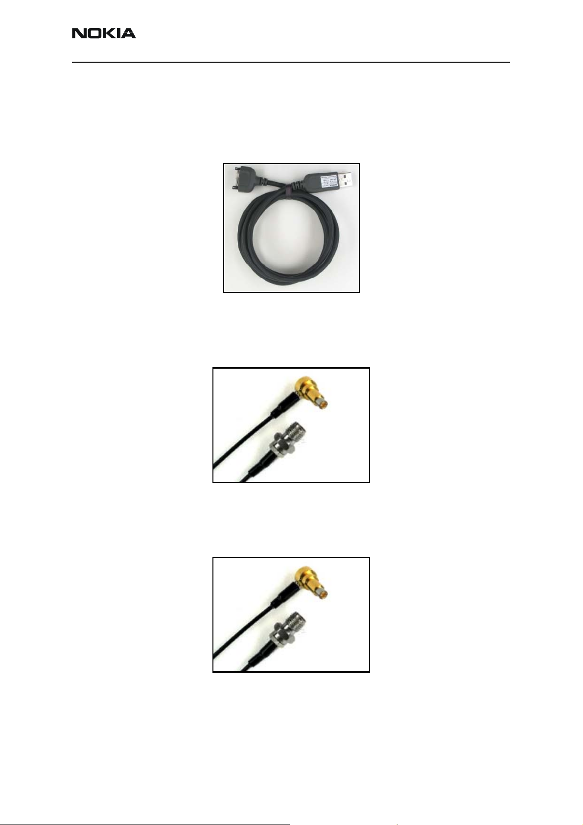
CA-53 Accessory/Flash Cable
The CA-53 allows bottom connector flashing using the FLS-4S Flash Device or the
FLC-20 Flash Device.
CA-56RS RF Test Cable
The CA-56RS test cable is used for RF engine troubleshooting with covers off. This cable
has a shorter probe making it more stable when connected to the PWB RF connector. The
CA-56RS supports testing of both GPS and Cellular engines on the mobile terminal.
CA-57RS RF Test Cable
The CA-57RS test cable is used for RF engine troubleshooting with covers on. This cable
has a longer RF probe allowing it to fit through the holes provided in the audio chamber
once the E-cover has been removed.
Issue 1 11/2005 ©2005 Nokia Corporation Company Confidential Page 3
Page 4
6265/6265i/6268 (RM-66)
Service Tools
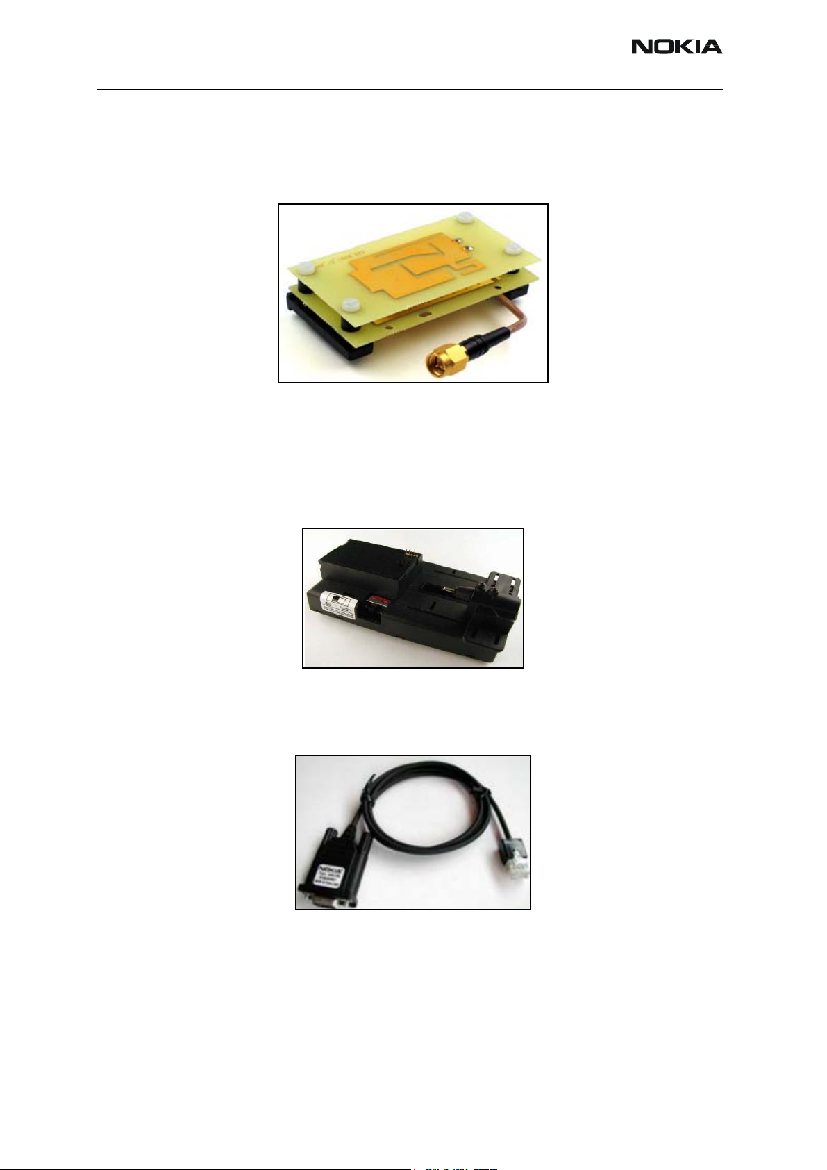
CPL-8 GPS Antenna Coupler
The CPL-8 allows authorized service centers to test the GPS antenna during handset
troubleshooting. The coupler is attached to (and detached from) the DA-57 Docking
Station Adapter.
Note: The DA-57 and the coupler assembly fit into the JXS-2 Shield Box
DA-57 Docking Station Adapter
The DA-57 works in conjunction with the JBV-1 Docking Station and the FPS-8, FPS-10
Prommer Boxes to allow calibration, and software flashing of the mobile terminal. The
DA-57 also has a built-in RUIM card reader and supports both Local and Normal modes.
DAU-9S FBUS/MBUS Cable
The DAU-9S is a general purpose cable that supports FBUS/MBUS communication
between a Mod-10 device and a PC.
Page 4 ©2005 Nokia Corporation Company Confidential Issue 1 11/2005
Page 5
6265/6265i/6268 (RM-66)
Nokia Customer Care Service Tools
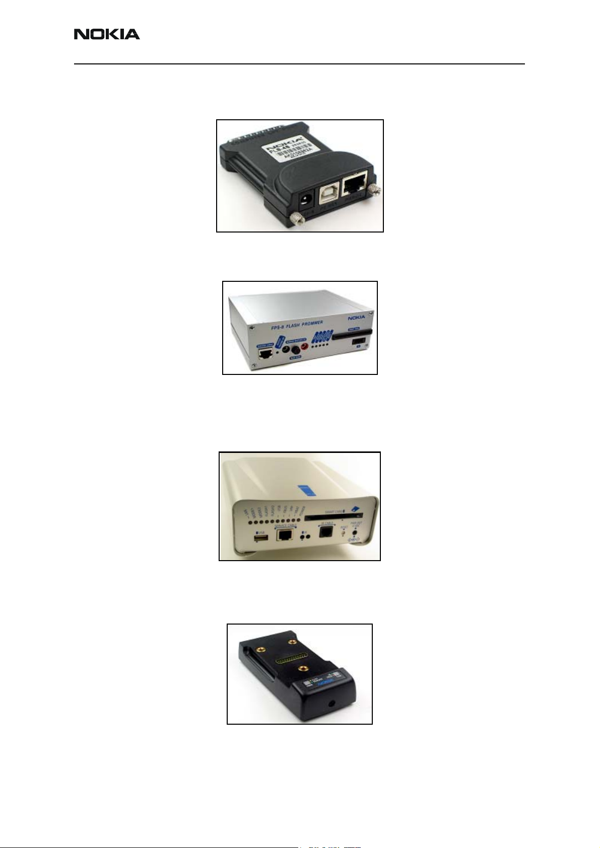
FLS-4S Flashing Device
The FLS-4S allows Point of Sale (POS) locations to flash the handset.
FPS-8 Flash Prommer
The FPS-8 is used for mobile terminal flashing at authorized service centers.
FPS-10 Flash Prommer
The FPS-10 replaces the FPS-8 Flash Prommer. The FPS-10 allows the flash code to be
pre-loaded into the unit's memory and then can be flashed directly to the handset at
high speeds.
JBV-1 Docking Station
The JBV-1 connects flash prommers. The docking station can be powered by the FPS-8/
FPS-10 Flash Prommers or by an external power supply.
Issue 1 11/2005 ©2005 Nokia Corporation Company Confidential Page 5
Page 6
6265/6265i/6268 (RM-66)
Service Tools
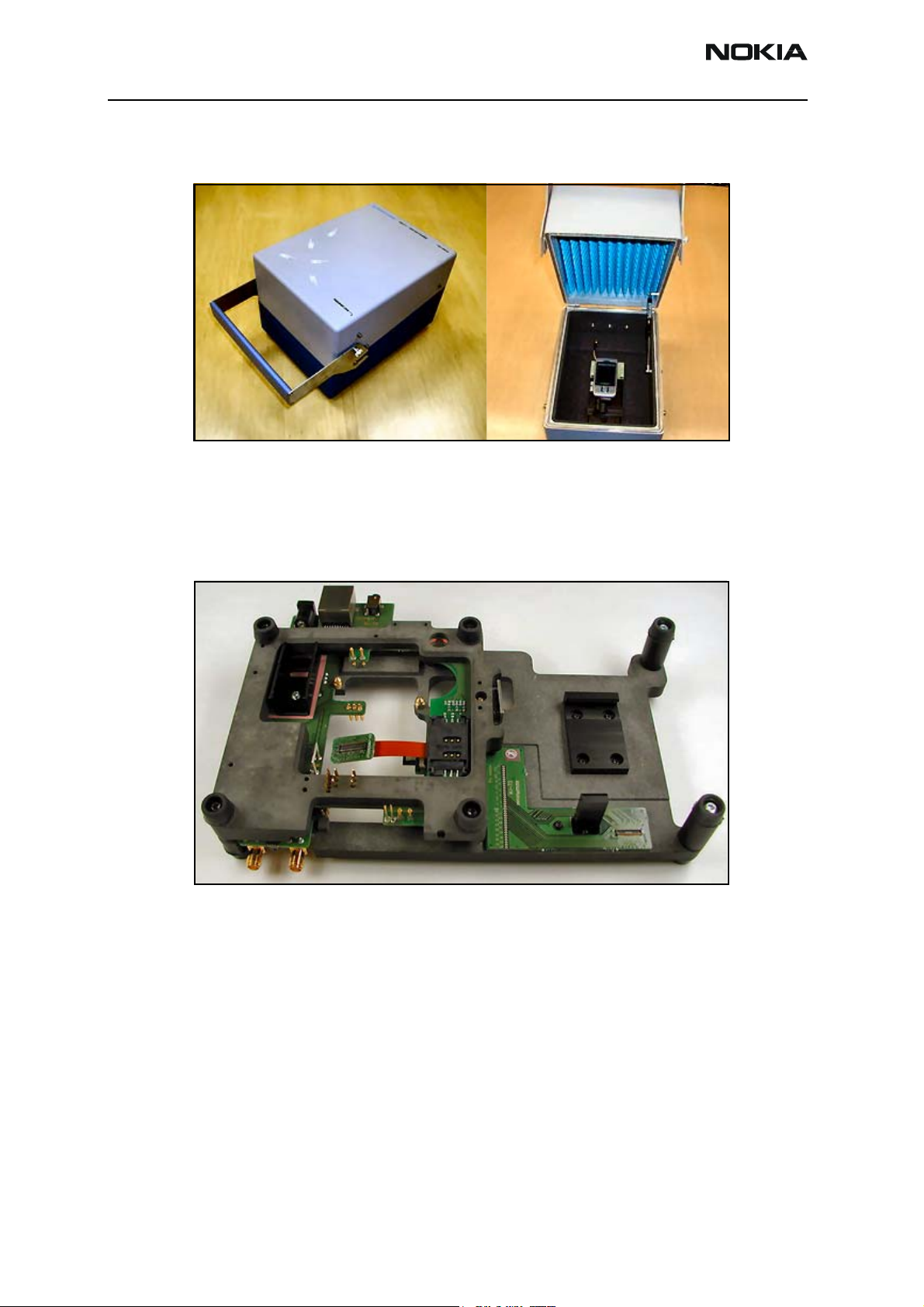
JXS-2 Shield Box
The JXS-2 is used to perform RF radiated testing and antenna testing.
MJ-73 Module Jig
The MJ-73 is used as a means to secure the PWBs and allows easy access to critical areas
for troubleshooting. It supports regulated and unregulated DC power input, local and
Normal mode operations, a headset jack for audio tests, a R-UIM card reader and a
second DC input for VCHAR used in EM tuning.
Page 6 ©2005 Nokia Corporation Company Confidential Issue 1 11/2005
Page 7

6265/6265i/6268 (RM-66)
Nokia Customer Care Service Tools
PKD-1 Software Security Dongle
The PKD-1 is a hardware dongle that, when connected to the parallel (LPT) port of the
PC, enables the use of the service software. It is not possible to use the service software
without the dongle. Printers or other peripheral devices can be connected to the PC
through the dongle, if needed.
Caution: Make sure that you have switched off the PC and the printer before making
connections.
Caution: Do not connect the PKD-1 to the serial port. You may damage your PKD-1
and/or your PC.
RJ-18 LGA Rework Jig and ST-16 PA Stencil
The ST-16 stencil allows rework on LGA-type components that do not have pre-tinned
pads. Both power amps require the use of this stencil. The stencil is designed to
specifically fit the N7300 and N7301 pad configurations and dimensions. The RJ-18 fits
the physical dimension of the N7300 and N7301.
Note: Used in conjunction with the SPS-1 Paste Spreader.
Issue 1 11/2005 ©2005 Nokia Corporation Company Confidential Page 7
Page 8

6265/6265i/6268 (RM-66)
Service Tools
RJ-55 LGA Rework Jig and ST-20 Stencil
The ST-20 stencil allows rework on LGA-type components that do not have pre-tinned
pads. The stencil is designed to specifically fit the N6601 pad configuration and
dimensions while the rework jig fits the physical dimension of the N6601.
Note: Used in conjunction with the SPS-1 Paste Spreader.
RJ-64 LGA Rework Jig and ST-24 Stencil
The ST-24 stencil allows rework on LGA-type components that do not have pre-tinned
pads. The stencil is designed to specifically fit the N7160 pad configuration and
dimensions while the rework jig fits the physical dimension of the N7160.
Note: Used in conjunction with the SPS-1 Paste Spreader.
Page 8 ©2005 Nokia Corporation Company Confidential Issue 1 11/2005
Page 9

6265/6265i/6268 (RM-66)
Nokia Customer Care Service Tools
RJ-65 LGA Rework Jig and ST-25 Stencil
The ST-25 stencil allows rework on LGA-type components that do not have pre-tinned
pads. The stencil is designed to specifically fit the N7000 pad configuration and
dimensions while the rework jig fits the physical dimension of the N7000.
Note: Used in conjunction with the SPS-1 Paste Spreader.
RJ-71 LGA Rework Jig and ST-26 Stencil
The ST-26 stencil allows rework on LGA-type components that do not have pre-tinned
pads. The stencil is designed to specifically fit the N6600 pad configuration and
dimensions while the rework jig fits the physical dimension of the N6600.
Note: Used in conjunction with the SPS-1 Paste Spreader.
Issue 1 11/2005 ©2005 Nokia Corporation Company Confidential Page 9
Page 10

6265/6265i/6268 (RM-66)
Service Tools
RJ-90 Soldering Jig
The RJ-90 serves as a mechanical holder for desoldering and soldering of components. It
provides a convenient means to replace components on the PWB when they are changed
during service repairs at authorized CARE locations.
Note: The RJ-90 is not intended to serve as a test jig.
RJ-100 LGA Rework Jig and ST-34 PA Stencil
The ST-34 stencil allows rework on LGA-type components that do not have pre-tinned
pads. The stencil is designed to specifically fit the N7200 pad configuration and
dimensions. The RJ-100 fits the physical dimension of the N7200.
Note: Used in conjunction with the SPS-1 Paste Spreader.
Page 10 ©2005 Nokia Corporation Company Confidential Issue 1 11/2005
Page 11

6265/6265i/6268 (RM-66)
Nokia Customer Care Service Tools
RJ-101 LGA Rework Jig and ST-35 PA Stencil
The ST-35 stencil allows rework on LGA-type components that do not have pre-tinned
pads. The stencil is designed to specifically fit the Z7302 pad configuration and
dimensions. The RJ-101 fits the physical dimension of the Z7302.
Note: Used in conjunction with the SPS-1 Paste Spreader.
SRT-6 Opening Tool
The SRT-6 is used to open and remove parts during disassembly of the mobile terminal.
SS-45 Camera Removal Tool
The SS-45 is used to remove the camera from its socket.
Issue 1 11/2005 ©2005 Nokia Corporation Company Confidential Page 11
Page 12

6265/6265i/6268 (RM-66)
Service Tools
SS-69 Domesheet Alignment Jig
The SS-69 is used to replace and align the domesheet on the PWB engine.
Note: The SS-69 is not intended to serve as a test jig.
XCS-4 MBUS/FBUS Cable
The XCS-4 is a general purpose cable for flashing and communicating with the mobile
terminal. It is used to connect the FPS-8 Flash Prommer to the docking station adapter or
the service jig.
Page 12 ©2005 Nokia Corporation Company Confidential Issue 1 11/2005
Page 13

6265/6265i/6268 (RM-66)
Nokia Customer Care Service Tools
Service Configurations
Service Setup 1
Item Name Type
Docking Station JBV-1
1 Docking Station Adapter DA-57
2 DC Power Cable PCS-1
3 Modular Cable XCS-4
4 Flash Prommer Box FPS-8 or FPS-10
5 Printer Cable
(included with FPS-8)
6 D9-D9 Cable
(included with FPS-8)
7 SW Protection Key PKD-1
8 AC Charger ACP-8F
CA-10DS
AXS-4
Issue 1 11/2005 ©2005 Nokia Corporation Company Confidential Page 13
Page 14

6265/6265i/6268 (RM-66)
Service Tools
Service Setup 2
Item Name Type
1 Module Jig MJ-73
2 DC Power Cable PCS-1
3RF Antenna Cable XRS-6
4 Service MBUS Cable DAU-9S
5 SW Protection Key PKD-1
6 RF Test Cable CA-57RS
Page 14 ©2005 Nokia Corporation Company Confidential Issue 1 11/2005
Page 15

6265/6265i/6268 (RM-66)
Nokia Customer Care Service Tools
Service Setup 3
Item Name Type
1 Docking Station JBV-1
2 Docking Station Adapter DA-57
3 DC Service Cable CA-52PS
4RF Antenna Cable XRS-6
5 DC Power Cable PCS-1
6 Service MBUS Cable DAU-9S
7 SW Protection Key PKD-1
Issue 1 11/2005 ©2005 Nokia Corporation Company Confidential Page 15
Page 16

6265/6265i/6268 (RM-66)
Service Tools
Service Setup 4: Automated Tuning and Alignment
Agilent E4420B
Signal Generator
2
10 MHz Out RF Output
Agilent 4406A
Vector Signal Analyzer
1
Ext Ref In RF Input
3
RF Switch
GPIB
6
Keithley 2306
Power Supply
GPIB
Parallel Serial
Dongle
4
Computer
5
RS 232
DC
SS-13 +
DA-57
RF
7
DCT4
Mobile
Terminal
Item Name MFR Model # QTY Comment
1 Vector Signal Analyzer Agilent E4406A 1 Options B78, BAC and BAE
2 Signal Generator Agilent E4421B 1 Digital signal generator with high-
stability oscillator and high-spectral
purity
3 RF Switch GreenHill TVi9901 1
4 Power Supply Keithley K2306 2 Programmable with sense wire
5 Win2000 PC 2 Dell with Pentium III or above,
network card, 256M RAM, 20GB HD,
CD-ROM, etc.
6 GPIB Interface NI GPIB-USB-A 2 USB to GPIB adapter (184983G-01)
7 Docking Station Nokia SS-13 1 For DCT4 handset tuning
8 10dB Attenuator
9 Security Key (Dongle) Nokia PDK-1
Page 16 ©2005 Nokia Corporation Company Confidential Issue 1 11/2005
Page 17

6265/6265i/6268 (RM-66)
Nokia Customer Care Service Tools
Service Setup 5: GPS Engine Testing
Use this setup for testing the GPS engine at Nokia Authorized Service Centers. Both
galvanic and radiated tests are supported. The GPS Test component in Phoenix provides
functionality to perform these tests. (See the Baseband Description and Troubleshooting
chapter for more information about GPS testing.)
GPS Engine Test Setup
GPS Galvanic Testing
1575.520125 MHz -110 dB
Signal Generator
50 Ohms
Power Supply
VOLTS AMPS
+3.8
-Gnd
Nokia PCS-1
Computer
CDMA
Nokia Dongle
Nokia DAU-9S
UUT
GPS
DA-57
JBV-1
Following is a list of equipment needed for galvanic GPS engine testing:
• Power supply
• Signal generator
• Computer (Pentium 3+, Windows 2000)
• JBV-1 Docking Station
• DA-57 Docking Station Adapter
• PCS-1 DC Power Cable
• DAU-9S MBUS/FBUS Cable
•PKD-1 Dongle
• SA-9 RF Support
• XRS-4 RF Test Cable
• Miscellaneous RF Cables
Issue 1 11/2005 ©2005 Nokia Corporation Company Confidential Page 17
Page 18

6265/6265i/6268 (RM-66)
Service Tools
GPS Antenna Test Setup
GPS Radiated Testing
1575.520152 MHz -92 dB
Signal Generator
50 Ohms
Power Supply
VOLTS AMPS
+3.8
-Gnd
Nokia PCS-1
Computer
Antenna
Coupler
Nokia Dongle
Nokia DAU-9S
JSX-1 Shield Box
UUT
DA-57
JBV-1
Following is a list of equipment needed for radiated GPS antenna testing:
• 4VDC power supply
• Signal generator
• Computer (Pentium 3+, Windows 2000)
• JBV-1 Docking Station
• DA-57 Docking Station Adapter
• PCS-1 DC Power Cable
• DAU-9S MBUS/FBUS Cable
•PKD-1 Dongle
• CPL-8 Antenna Coupler
• SA-8 RF Support
• XRS-4 RF Test Cable
• JXS-1 Shield Box
• Miscellaneous RF cables
Page 18 ©2005 Nokia Corporation Company Confidential Issue 1 11/2005
 Loading...