

Page 1
Nokia Mobile Phones Customer Care E&A
Technical Services, Repair Concepts Confidential 13.02.2002
PAGE 1 (19) Approved 1.0
SQX –00380-en MWy
Service Manual
Nokia 5210
NSM-5
Service Level 1
Copyright © Nokia Mobile Phones. This material, including documentation and any related computer
programs, is protected by copyright controlled by Nokia Mobile Phones. All rights are reserved.
Copying, including reproducing, storing, adapting or translating, any or all of this material requires
the prior written consent of Nokia Mobile Phones. This material also contains confidential
information, which may not be disclosed to others without the prior written consent of Nokia Mobile
Phones.
Service Manual 5210 Level 1 Copyright 2002 © Nokia Corporation
Page 2

Nokia Mobile Phones Customer Care E&A
Technical Services, Repair Concepts Confidential 13.02.2002
PAGE 2 (19) Approved 1.0
SQX –00380-en MWy
Introduction
The purpose of this document is to give Nokia service level 1 workshops aids to carry out
service for 5210. The use of this Service Manual is only for Nokia authorized service
partners additionally to other service documentation like Service Bulletins.
While every endeavor has been made to ensure the accuracy of this document, some
errors may exist. If you find any errors or if you have further suggestions, Nokia should
be notified. Please keep in mind also that this documentation is continuously being
updated and modified, so watch always out for the newest version.
Warnings and Cautions
Please refer to the phone’s user guide for instructions relating to operation, care and maintenance
including important safety information. Note also the following:
Warnings:
1. CARE MUST BE TAKEN ON INSTALLATION IN VEHICLES FITTED WITH ELECTRONIC ENGINE
MANAGEMENT
SYSTEMS AND ANTI–SKID BRAKING SYSTEMS. UNDER CERTAIN FAULT CONDITIONS, EMITTED RF
ENERGY CAN AFFECT THEIR OPERATION. IF NECESSARY, CONSULT THE VEHICLE
DEALER/MANUFACTURER TO DETERMINE THE IMMUNITY OF VEHICLE ELECTRONIC SYSTEMS TO RF
ENERGY.
2. THE HANDPORTABLE TELEPHONE MUST NOT BE OPERATED IN AREAS LIKELY TO CONTAIN
POTENTIALLY EXPLOSIVE ATMOSPHERES EG PETROL STATIONS (SERVICE STATIONS), BLASTING AREAS
ETC.
3. OPERATION OF ANY RADIO TRANSMITTING EQUIPMENT, INCLUDING CELLULAR TELEPHONES, MAY
INTERFERE WITH THE FUNCTIONALITY OF INADEQUATELY PROTECTED MEDICAL DEVICES. CONSULT A
PHYSICIAN OR THE MANUFACTURER OF THE MEDICAL DEVICE IF YOU HAVE ANY QUESTIONS. OTHER
ELECTRONIC EQUIPMENT MAY ALSO BE SUBJECT TO INTERFERENCE.
Cautions:
1. Servicing and alignment must be undertaken by qualified personnel only.
2. Ensure all work is carried out at an anti–static workstation and that an anti–static wrist strap is
worn.
3. Ensure solder, wire, or foreign matter does not enter the telephone as damage may result.
4. Use only approved components as specified in the parts list.
5. Ensure all components, modules screws and insulators are correctly re–fitted after servicing and
alignment. Ensure all cables and wires are repositioned correctly.
6. All PC’s used with NMP Service Software for this produce must be bios and operating system ”Year
2000 Compliant”.
Service Manual 5210 Level 1 Copyright 2002 © Nokia Corporation
Page 3

Nokia Mobile Phones Customer Care E&A
Technical Services, Repair Concepts Confidential 13.02.2002
PAGE 3 (19) Approved 1.0
SQX –00380-en MWy
Table of content
1. EXPLODED VIEW.................................................................................................................................... 5
2. BILL OF REPAIR...................................................................................................................................... 6
3. GENERAL REPAIR INFORMATION ................................................................................................... 8
4. DISASSEMBLY INSTRUCTIONS .......................................................................................................... 9
5. SW-UPDATE ............................................................................................................................................ 12
6. MAIN PARTS........................................................................................................................................... 13
7. QUICK TROUBLE SHOOTER PART1 ............................................................................................... 14
8. QUICK TROUBLE SHOOTER PART2 ............................................................................................... 15
9. QUICK TROUBLE SHOOTER PART3 ............................................................................................... 16
10. ESD PROTECTION REQUIREMENTS........................................................................................... 17
11. SERVICE NOTES................................................................................................................................ 18
12. GONOGO TESTER............................................................................................................................. 19
13. BATTERYTESTER ............................................................................................................................. 19
Service Manual 5210 Level 1 Copyright 2002 © Nokia Corporation
Page 4
Nokia Mobile Phones Customer Care E&A
PAGE 4 (19) Approved 1.0
SQX –00380-en MWy
Technical Services, Repair Concepts Confidential 13.02.2002
Change History
Originator Status Version No. Date Comments
MWy Draft 0.1 17.01.2002 Initial draft
MWy Approved 1.0 13.02.2002
Service Manual 5210 Level 1 Copyright 2002 © Nokia Corporation
Page 5
Nokia Mobile Phones Customer Care E&A
Technical Services, Repair Concepts Confidential 13.02.2002
PAGE 5 (19) Approved 1.0
SQX –00380-en MWy
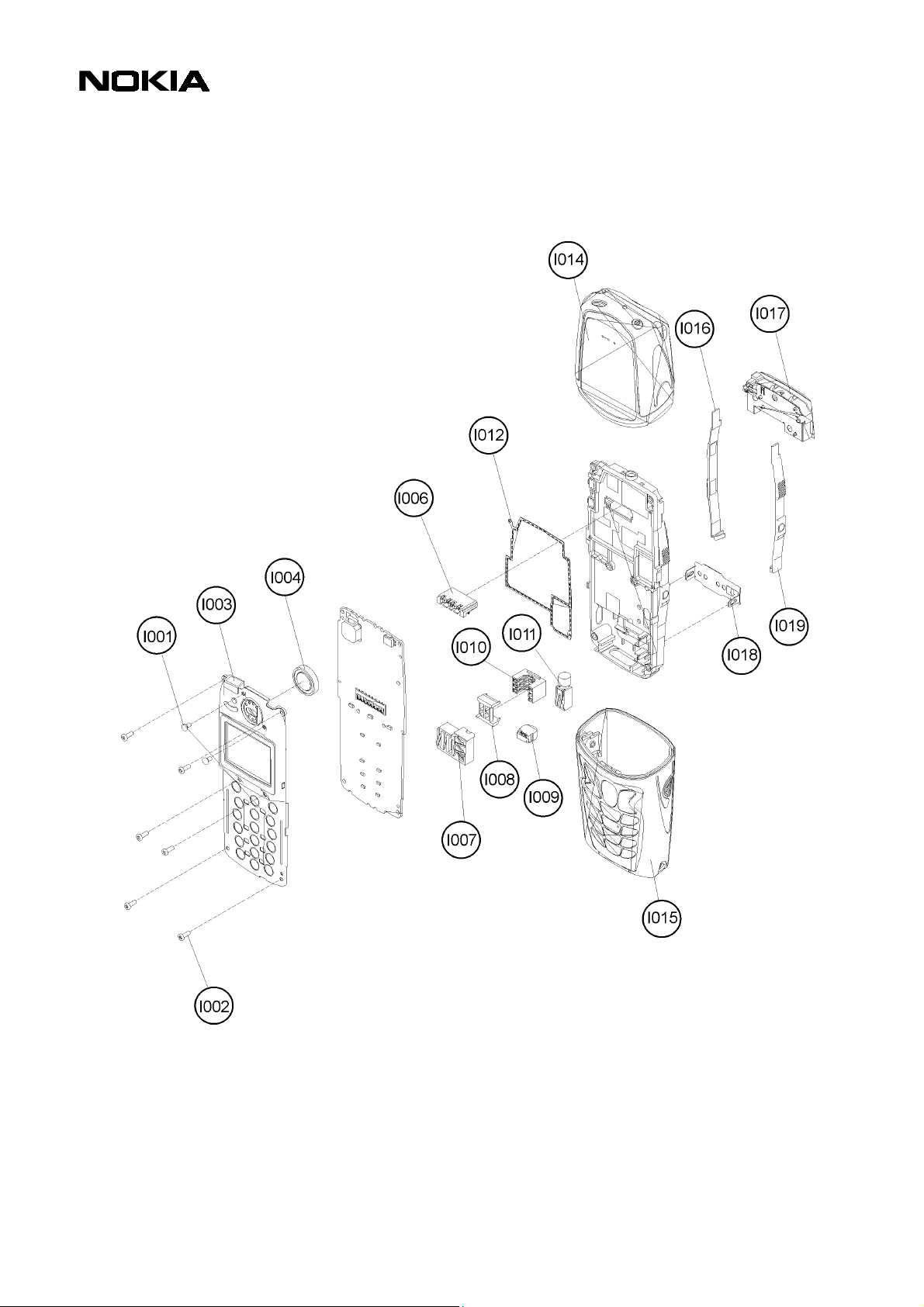
1. EXPLODED VIEW
Description: See corresponding ITEM/CIRCUIT REF of the BOR (Bill Of Repair)
Service Manual 5210 Level 1 Copyright 2002 © Nokia Corporation
Page 6
Nokia Mobile Phones Customer Care E&A
Technical Services, Repair Concepts Confidential 13.02.2002
PAGE 6 (19) Approved 1.0
SQX –00380-en MWy
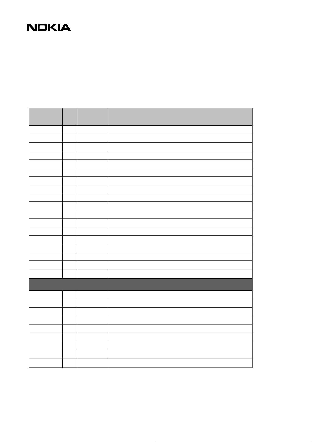
2. BILL OF REPAIR
SPARE PARTS
ITEM/
CIRCUIT REF.
I001 2 6290103 Screw 1.6x3.2 (Use 8 Ncm torque)
I002 6 6190049 Screw 1.6x5.3 (Use 17 Ncm torque)
I003 1 4850205 LCD module assy
I004 1 5140067 Speaker + spring
I006 1 5409093 Battery connector 4 pole
I007 1 5409095 DC & HF connector
I008 1 9660147 Twin Rip
I009 1 5140175 Microphone + holder + springs
I010 1 5409155 SIM connector
I011 1 6800041 Vibra assy
I012 1 9480791 RF gasket
I016 1 9510836 Release spring left
I017 1 0660249 Antenna
I018 1 9560085 SIM spring
I019 1 9510829 Release spring right
0772026 Spare Part Kit
0080628 Refurbishment Kit
QTY PART NO PART NAME
VARIANT PARTS
I014 1 9458284 A-SHELL ASSY BURNED ORANGE NSM-5
I015 1 9458286 B-SHELL ASSY BURNED ORANGE NSM-5
I015 1 9490544 B-SH ASSY BURNED FOR FUNKY ARABIC
I015 1 9490545 B-SH ASSY BURNED FOR FUNKY HEBREW
I015 1 9490546 B-SH ASSY BURNED FOR FUNKY CYRILLI
I014 1 9490498 A-SHELL ASSY WAVE BLUE FUNKY
I015 1 9490501 B-SHELL ASSY WAVE BLUE FUNKY LATIN
I015 1 9490534 B-SHELL ASSY WAVE BLUE FUNKY STROKE
Service Manual 5210 Level 1 Copyright 2002 © Nokia Corporation
Page 7

Nokia Mobile Phones Customer Care E&A
Technical Services, Repair Concepts Confidential 13.02.2002
SWAP UNITS
QTY PART NO PART NAME
0073338 NSM-5NX SWAP ENGINE
0073335 NSM-5NX SWAP ENGINE TURKEY
0073336 NSM-5NX SWAP ENGINE RUSSIAN
0073337 NSM-5NX SWAP ENGINE FRANCE
0073343 NSM-5NX SWAP ENGINE CZECH
0073419 NSM-5NX SWAP ENGINE POLAND
SERVICE TOOLS
PAGE 7 (19) Approved 1.0
SQX –00380-en MWy
QTY PART NO PART NAME
0271570 BATTERY BLB-2 LI-ION 650 MAH
0081483 POS FLASH DONGLE FLS-4
0272169 AC TRAVEL CHARGER ACP-8E (EUR)
0272172 AC TRAVEL CHARGER ACP-8X (UK)
0730218 POS SERVICE CABLE XCS-1
0081346 POS FLASH LOADING ADAPTER FLA-10
0774071 Service SW Diskette 3.5" WinTesla
0774080 Service SW Diskette 3.5" for NSM-5
0273195 HEAD-SET DOUBLE MONO HDD-1
0770226 BATTERY EXTRACTOR TOOL SRT-3
Service Manual 5210 Level 1 Copyright 2002 © Nokia Corporation
Page 8

Nokia Mobile Phones Customer Care E&A
Technical Services, Repair Concepts Confidential 13.02.2002
PAGE 8 (19) Approved 1.0
SQX –00380-en MWy
3. GENERAL REPAIR INFORMATION
In this section you will get some general hints how to carry out repairs:
Before starting the repair you must take care of ESD precautions like being in your
o
ESD-area and connecting your arm wrist.
Use gloves to avoid corrosion and fingerprints.
o
When cleaning the pads you have to use a soft cloth and isopropanol. It is not
o
allowed to use a glass fiber pencil because it scratches the surface and will lead
later on to corrosion.
Mechanical parts, which didn’t repair the failure, can be reused, if they are not
o
soldered.
Use always original Nokia parts or accessories.
o
Don’t’ try to repair liquid damages.
o
Meet the torque requirements when assembling the unit (see also the document
o
“torques for transceiver assembly” on Partner Websites).
Always use your own equipment for testing where you are sure that it works. E.g.
o
if the customer complains about charger function, please test the phone with your
own charger to be sure if phone or charger causes the malfunction.
The bottom side of a module is the side where the part no. of the pcb is seen.
o
Please check Partner Websites (PWS) for latest news on a regular basis
o
Simple Infrared Test:
You need another NOKIA infrared device to do an infrared test.
Make sure that infrared is activated in receiver device (e. g.: another 5210).
Explanation:
In Quotation marks = push button
Bold = choose text
• “Names”
• Search, “Select”
• “ok”
• “Details”
• “Options”
• Push 4 times “Arrow down”
• Send via IR “Select”
If the business card is not sent/received make sure that receiver device is within reach (aprox. 15 cm).
After successful sending push “Back” and then “Exit”.
Service Manual 5210 Level 1 Copyright 2002 © Nokia Corporation
Page 9

Nokia Mobile Phones Customer Care E&A
Technical Services, Repair Concepts Confidential 13.02.2002
PAGE 9 (19) Approved 1.0
SQX –00380-en MWy
4. DISASSEMBLY INSTRUCTIONS
To open the unit the A-Shell has to be removed first.
Press the grip markings on both sides of the B-Shell
and pull the A-Shell apart from the B-Shell.
Now, press the release springs near the display and
pull the unit out of the B-Shell.
Remove the six screws with screwdriver Torx T6 in
the shown order. When assembling the reverse
order has to be taken with torque of 17Ncm.
All the connectors are located under the CMT
module. Take care that the RF Gasket stays in
position on the four guiding pins. If the gasket is
bent it has to be changed.
Now the LCD module can be removed easily.
The SIM Connector can be removed with tweezers.
Service Manual 5210 Level 1 Copyright 2002 © Nokia Corporation
Page 10

Nokia Mobile Phones Customer Care E&A
Technical Services, Repair Concepts Confidential 13.02.2002
If you assemble the SIM Connector, be aware that
the Twin Rip is also fitted correctly. The Twin Rip is
PAGE 10 (19) Approved 1.0
When the SIM Connector is removed, t
Connector can be taken away.
SQX –00380-en MWy
responsible to keep the SIM Connector in the right
position.
he DC + HF
The Vibra Motor with its rubber case is squeezed into
the B-Cover like the Microphone. Do not grab the
spring connectors, because they may be damaged
when pulling the microphone. To change the
Microphone, push it up carefully with tweezers.
If you need to change the SIM Spring you first have
to release the two lockings.
With the Battery Connector Extractor Tool SRT-3
used in 8210 you can easily push out the Battery
Connector without bending the sensible contacts.
For changing the plastic Release Springs the lower
sides have to be unlocked first.
Service Manual 5210 Level 1 Copyright 2002 © Nokia Corporation
Page 11

Nokia Mobile Phones Customer Care E&A
Technical Services, Repair Concepts Confidential 13.02.2002
Pull up the lower side of the Release Spring and take
it out of the upper holder.
PAGE 11 (19) Approved 1.0
SQX –00380-en MWy
The Antenna is fixed with four snaps. It is enough, if
you release with tweezers the two snaps at the
battery side.
Move up the antenna as shown in the picture. Take
care not to damage the antenna contacts. The metal
is very sensitive against corrosion, so please don’t
touch the metal with your fingers. Use gloves
instead.
Remove the protection foil of the display and unlock
the snaps on both sides of the display frame.
The final GoNoGo test verifies that the electrical specifications will be fulfilled.
It is also possible to change the speaker, if needed.
Therefore you have to unscrew these two screws.
Remember to use torque of 8 Ncm when
tightening the speaker screws.
Replace the protection foil. Now you have the
separated plastic frame of the LCD unit. You can now
slightly push out the speaker with your fingers or
tweezers.
Service Manual 5210 Level 1 Copyright 2002 © Nokia Corporation
Page 12

Nokia Mobile Phones Customer Care E&A
Technical Services, Repair Concepts Confidential 13.02.2002
PAGE 12 (19) Approved 1.0
SQX –00380-en MWy
5. SW-UPDATE
To use FLS-4 Flash Dongle you have to follow the user guide inside the sales package. Please
check always the latest version of flash software, which is available on Partner Website.
Flash Concept – (Point of Sales)
Description: See corresponding ITEM/CIRCUIT REF of the BOR (Bill Of Repair)
Service Manual 5210 Level 1 Copyright 2002 © Nokia Corporation
Page 13

p
Nokia Mobile Phones Customer Care E&A
Technical Services, Repair Concepts Confidential 13.02.2002
PAGE 13 (19) Approved 1.0
SQX –00380-en MWy
6. MAIN PARTS
HF+DC Connector I007 Microphone I009 Vibra Motor I011
Battery Connector I006 Antenna I017 S
eaker I004
SIM Connector I010 Twin Rip I008 SIM Spring I018
Batt.Conn.Extractor SRT-3 RF Gasket I012 Release Spring L I016; R I019
A-Shell I014; B-Shell I015 LCD Module I003
Service Manual 5210 Level 1 Copyright 2002 © Nokia Corporation
B-Cover, not changeable
Page 14

7. QUICK TROUBLE SHOOTER PART1
Service Manual 5210 Level 1 Copyright 2002 © Nokia Corporation
Page 15

8. QUICK TROUBLE SHOOTER PART2
Service Manual 5210 Level 1 Copyright 2002 © Nokia Corporation
Page 16

9. QUICK TROUBLE SHOOTER PART3
Service Manual 5210 Level 1 Copyright 2002 © Nokia Corporation
Page 17

Nokia Mobile Phones Customer Care E&A
Technical Services, Repair Concepts Confidential 13.02.2002
PAGE 17 (19) Approved 1.0
SQX 00380-en MWy
10. ESD PROTECTION REQUIREMENTS
Electrostatic discharge can easily damage the sensitive components of
electronic products. Therefore every Service Partner has to take care of
at least some precautions like ESD restricted area, floor, table, covering,
chair(s), shoes or arm wrist.
Please refer to the Partner Website document
ESD protection requirements for NMP Service Level 1/2 Service Suppliers
example configuration of an epa-area
source: www.armeka.com
example workbench and testers
source: http://www.armekaengineering.com
example configuration of a workbench
source: www.warmbier.com
Service Manual 5210 Level 1 Copyright 2002 © Nokia Corporation
Page 18

Nokia Mobile Phones Customer Care E&A
Technical Services, Repair Concepts Confidential 13.02.2002
PAGE 18 (19) Approved 1.0
SQX 00380-en MWy
11. SERVICE NOTES
We recommend using Service Notes when shipping phones to other Service Partners. It
prevents the product from scratches, it is ESD-proved and has the possibility to give
valuable feedback of the fault symptom through a structured form.
Please refer to the document
Service Notes for faulty NMP transceiver
on Partner
Website to get further information.
Service Manual 5210 Level 1 Copyright 2002 © Nokia Corporation
Page 19

Nokia Mobile Phones Customer Care E&A
Technical Services, Repair Concepts Confidential 13.02.2002
PAGE 19 (19) Approved 1.0
SQX 00380-en MWy
12. GONOGO TESTER
The Acterna/Wavetek GoNoGo Tester
has to be used to carry out the final
test after your service action to
guarantee the functionality of the
phone.
Please refer to the actual
information in the Nokia Care
Point Extranet within the Partner
Website.
13. BATTERYTESTER
The Astratec battery tester
lets you test the capacity
of Nokia batteries.
Please refer to the actual
information in the Nokia
Care Point Extranet
within the Partner
Website.
Service Manual 5210 Level 1 Copyright 2002 © Nokia Corporation
 Loading...