

Page 1

PAMS Technical Documentation
NSB–1/3 Series Transceivers
Tuning Instructions
Original 06/98
Page 2

NSB–1/3
PAMS
Tuning Instructions
CONTENTS
Tuning Instructions 3. . . . . . . . . . . . . . . . . . . . . . . . . . . . . . . . . . . . . .
General 3. . . . . . . . . . . . . . . . . . . . . . . . . . . . . . . . . . . . . . . . . . . . .
Required Equipment 4. . . . . . . . . . . . . . . . . . . . . . . . . . . . . . . . . .
Equipment Setup 4. . . . . . . . . . . . . . . . . . . . . . . . . . . . . . . . . . . . .
Equipment Setup for Tuning a Phone without Removing Covers 5
Flash Concept for NSB–1/3 6. . . . . . . . . . . . . . . . . . . . . . . . . .
Light Flash Concept for NSB–1/3 7. . . . . . . . . . . . . . . . . . . . .
Tuning With Covers Off – Using Test–frame JBS–19 8. . . .
Tuning With Covers Off – using Light Jig JBT–1 9. . . . . . . .
Warranty Transfer 10. . . . . . . . . . . . . . . . . . . . . . . . . . . . . . . . . .
Tuning Steps 11. . . . . . . . . . . . . . . . . . . . . . . . . . . . . . . . . . . . . . . . .
1. RX Calibration (AGC + AFC) 11. . . . . . . . . . . . . . . . . . . . . .
2. I/Q Modulator Amplitude Balance and Phase Shift Tuning 12
3. Tuning of Transmitter Power Levels 14. . . . . . . . . . . . . . . .
4. Energy Management Calibration 15. . . . . . . . . . . . . . . . . . .
Technical Documentation
Page 2
Original 06/98
Page 3

PAMS
NSB–1/3
Technical Documentation
Tuning Instructions
General
All tuning operations of the NSB–1/3 are carried out using the service
software. The service software turns the phone into the locals mode, in
which the phone can be outwardly controlled via the MBUS interface.
Tuning is based on the software communicating with the D/A and A/D
converters of the phone. In some instances the phone processor will also
calculate the required correction parameter.
The tuning values of the phone reside on the EEPROM. The contents of
the EEPROM can be read by the service software and saved as a file.
This is advisable when there is need to retain that information, e.g. in
view of replacement of the circuit. The program also enables writing the
default parameters on the EEPROM, in which case all tuning steps should
be carried out.
Tuning Instructions
During tuning, proceed as follows:
– Take care not to damage sensitive measuring instruments with exces-
sive RF power.
– Carry out all tuning steps in the shortest possible time to avoid exces-
sive heating of RF units.
– Perform all tuning steps in the order presented.
– Never try to mask a fault by tuning it out!
Original 06/98
Page 3
Page 4

NSB–1/3
PAMS
Tuning Instructions
Required Equipment
– PC/AT computer with service software; see separate section for
instructions on installation and use.
– Service accessories; see equipment setup pictures.
– Multimeter or DVM.
– GSM radio telephone test station or separate measuring equipment as
follows:
– RF generator
– pulse power meter
– spectrum analyzer
– attenuator and branching unit
Equipment Setup
Technical Documentation
Caution: Make sure that you have switched off the PC and the printer
before making connections !
Caution: Do not connect the PKD–1 key to the serial port. You may
damage your PKD–1 !
Attach the protection key PKD–1 to parallel port one (25–pin female
D–connector) of the PC. When connecting the PKD–1 to the parallel port
be sure that you insert the PC end of the PKD–1 to the PC (male side). If
you use a printer on parallel port one, place the PKD–1 between the PC
and your printer cable.
Next connect the M2BUS service cable, DAU–9P, to the serial port
(RS–232) of the computer. Attach one end of the service cable to the PC
serial port and the other end to the service box, JBA–4. For servicing the
phone with the covers in place the service box should always be used.
When the phone covers are removed the jigs should be used.
For audio measurements connect the audio cable, ADS–1, as follows:
– EAR line to AF INPUT of test equipment
– MIC line to MOD GEN OUTPUT of test equipment
Page 4
Original 06/98
Page 5
PAMS
NSB–1/3
Technical Documentation
Tuning Instructions
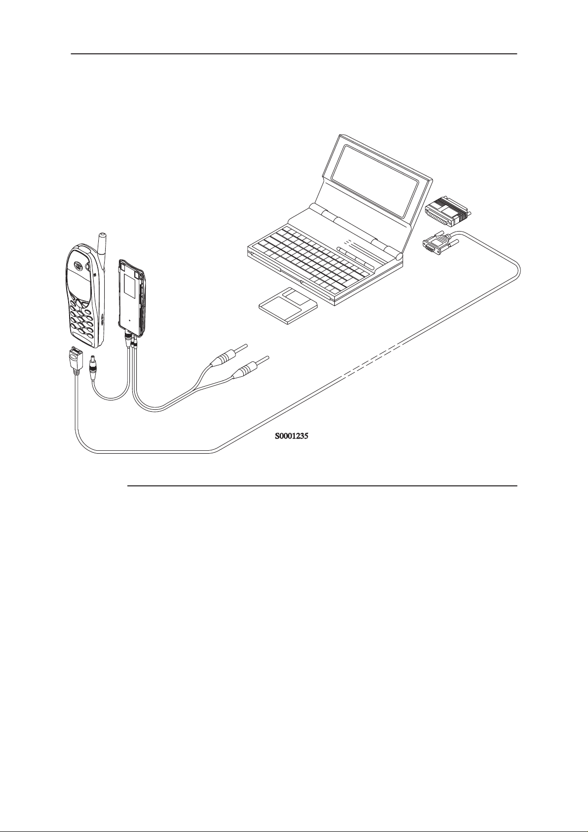
Equipment Setup for Tuning a Phone without Removing Covers
4.
1.
5.
2.
3.
Item: Service accessory: Product code:
1 Service Battery BBD–3 0775071
2 DC Cable SCB–3 0730114
3 Service MBUS Cable DAU–9P 0730109
4 Software protection key PKD–1 0750018
5 Service SW diskette 3.5” 0774080
Original 06/98
Page 5
Page 6

NSB–1/3
PAMS
Tuning Instructions
Flash Concept for NSB–1/3
12.
4.
6.
Technical Documentation
10.
13.
11.
9A.
7.
9B. 8.
5.
1.
2.
3.
Item: Service accessory: Product code:
1 Flash Loading Adapter FLA–5 0080178
2 Flash Security Box TDF–4 0770106
3 Prommer FPS–4S 0085095
4 Service Battery BBD–3 0775071
5 Service Cable SCH–5 0730098
6 DC Cable PCC–1 0730053
7 D15 – D15 Cable AXS–5 0730091
(Included in FLA–5 sales pack)
8 Printer Cable (Included in FPS–4 sales pack) 0730029
9A D9 – D9 Cable AXS–4 0730090
(Included in FPS–4 sales pack)
9B D9 – D9 Cable AXS–4 0730090
10 Software protection key PKD–1 0750018
11 Service SW diskette 3.5” 0774080
12 Travel Charger ACH–6E (Euro) 0270381
Travel Charger ACH–6U (USA/Japan) 0270382
Travel Charger ACH–6X (UK) 0270380
13 AC Charger ACL–3E 0680015
(Included in FPS–4 sales pack)
Page 6
Original 06/98
Page 7

PAMS
NSB–1/3
Technical Documentation
Light Flash Concept for NSB–1/3
11.
10.
5.
3.
Tuning Instructions
9.
6.7. 8.
4.
1.
2.
Item: Service accessory: Product code:
1 Flash Loading Adapter FLA–5 0080178
2 Flash Security Box TDF–4 0770106
3 Service Battery BBD–3 0775071
4 Service Cable SCH–5 0730098
5 DC Cable PCC–1 0730053
6 D9 – D9 Cable AXS–4 0730090
7 Light Flash Cable FLC–5 0770107
8 XCM–1
9 Software protection key PKD–1 0750018
10 Service SW diskette 3.5” 0774080
11 Travel Charger ACH–6E (Euro) 0270381
Travel Charger ACH–6U (USA/Japan) 0270382
Travel Charger ACH–6X (UK) 0270380
Original 06/98
Page 7
Page 8

NSB–1/3
PAMS
Tuning Instructions
Technical Documentation
Tuning With Covers Off – Using Test–frame JBS–19
3.
4.
9.
6.
1.
8.
7.
5.
2.
Item: Service accessory: Product code:
1 Module Jig JBS–19 * 0770098
2 Service Audio Box JBA–4 ** 0770094
3 DC Cable PCS–1 0730012
4 External Antenna Cable XRC–1B 0730128
5 Service Cable SCH–5 ** 0730098
6 Service MBUS Cable DAU–9S ** 0730108
7 Audio Cable ADS–1 0730011
8 Software Protection Key PKD–1 0750018
Page 8
9 Service SW diskette 3.5” 0774080
*) The nominal operating voltage for JBS–19 is 3.6 V.
The supply voltage for JBS–19 must never exceed 5.0 V
**) SCH–5, JBA–4, and DAU–9S can be replaced with DAU–9P
Original 06/98
Page 9

PAMS
NSB–1/3
Technical Documentation
Tuning With Covers Off – using Light Jig JBT–1
3.
4.
1.
1.
7.
Tuning Instructions
8.
6.
5.
2.
Item: Service accessory: Product code:
1 Light Module Jig JBT–1 * 0770109
2 Service Audio Box JBA–4 ** 0770094
3 DC Cable PCS–1 0730012
4 External Antenna Cable XRC–1B 0730128
5 Service Cable SCH–5 ** 0730098
6 Audio Cable ADS–1 0730011
7 Service MBUS Cable DAU–9S ** 0730108
8 Software Protection Key PKD–1 0750018
9 Service SW diskette 3.5” 0774080
*) The nominal operating voltage for JBT–1 is 3.6 V.
**) SCH–5, JBA–4, and DAU–9S can be replaced with DAU–9P
Original 06/98
The supply voltage for JBT–1 must never exceed 5.0 V
Page 9
Page 10

NSB–1/3
PAMS
Tuning Instructions
Warranty Transfer
Technical Documentation
1.
Item: Service accessory: Product code:
1 Warranty Cable SCH–6 0730099
Page 10
Original 06/98
Page 11

PAMS
NSB–1/3
Technical Documentation
Tuning Steps
1. RX Calibration (AGC + AFC)
Reference values for the received signal strength meter are program
tuned.
RSSI reference signal level programming:
– Select
– Check that the program asks you to use 1960.867710 MHz.
If it doesn’t, change the continuous mode channel to 665 in RF Controls window.
– Connect RF signal generator to the external antenna connector of the
phone.
– Adjust signal generator to 1960.867710 MHz.
Tuning –> RX Calibration
Tuning Instructions
– Adjust signal generator level to –60 dBm + cable attenuation.
– Press
– Adjust signal generator level to –90 dBm + cable attenuation.
– Press
Service software reports:
A Table of AFC Parameters:
A Table for AGC Calibration:
If Calibration fails Service software reports that with error message or
some tuning value is fail.
OK
button
OK
button.
AFC INIT Value
AFC Slope
PSW Slope
AGC in 3 db steps 0...57 dB
DAC and voltage reading for each gain value
Each DAC step should be 12 to 25.
– Press
Original 06/98
SAVE
button
Page 11
Page 12

NSB–1/3
PAMS
Tuning Instructions
Technical Documentation
2. I/Q Modulator Amplitude Balance and Phase Shift Tuning
The purpose of this tuning operation is to adjust the I/Q modulator d.c. offsets and the I/Q modulator amplitude balance and phase shift.
I/Q modulator d.c. offsets, amplitude balance and phase shift tuning:
– Connect spectrum analyzer (with an attenuator if needed) to the exter-
nal antenna connector of the phone.
– Select
– Select I/Q tuning values from the PC’s memory, the phone’s EEPROM
or factory default values.
– Check that the channel is 661 and the TX Data Type is Cont1.
If it doesn’t, change it in RF Controls window.
– Adjust spectrum analyzer centre frequency to 1880 MHz, Span 200
kHz, Res BW 10 kHz, Video BW 1 kHz and Sweep time 0.5 s – 1s.
Tuning –> TX I/Q...
–67.71 kHz +67.71 kHz
D.C. offset
tunings:
Set this value
to minimum
CHF
– Select the ”TX I d.c. offset” option.
> 30 dB
> 35 dB
Amplitude &
phase difference:
Set this value
to minimum
Page 12
– Adjust the level of centre frequency (CHF signal) to minimum by vary-
<–
ing D/A converter value with
and –> buttons.
– The amplitude difference between CHF–67.7 kHz and CHF should be
>30 dB.
– Select option ”TX Q d.c. offset”.
– Adjust the level of signal CHF to minimum by varying D/A converter
<–
and
–>
value with
keys.
Original 06/98
Page 13

PAMS
NSB–1/3
Technical Documentation
– Use the ”Amplitude Difference” option.
– Adjust the level of signal CHF+67.7 kHz (1880.06771 MHz) to mini-
mum by varying D/A converter value with <– and –> keys.
– The amplitude difference between CHF+67.7 kHz and CHF–67 kHz
should be >35 dB.
– Select the ”Phase Difference” option.
– Adjust the level of signal CHF+67.7 kHz to minimum by varying D/A
converter value with <– and –> keys.
– When values are correct press
SAVE
Tuning Instructions
button.
Original 06/98
Page 13
Page 14
NSB–1/3
Á
Á
Á
Á
PAMS
Tuning Instructions
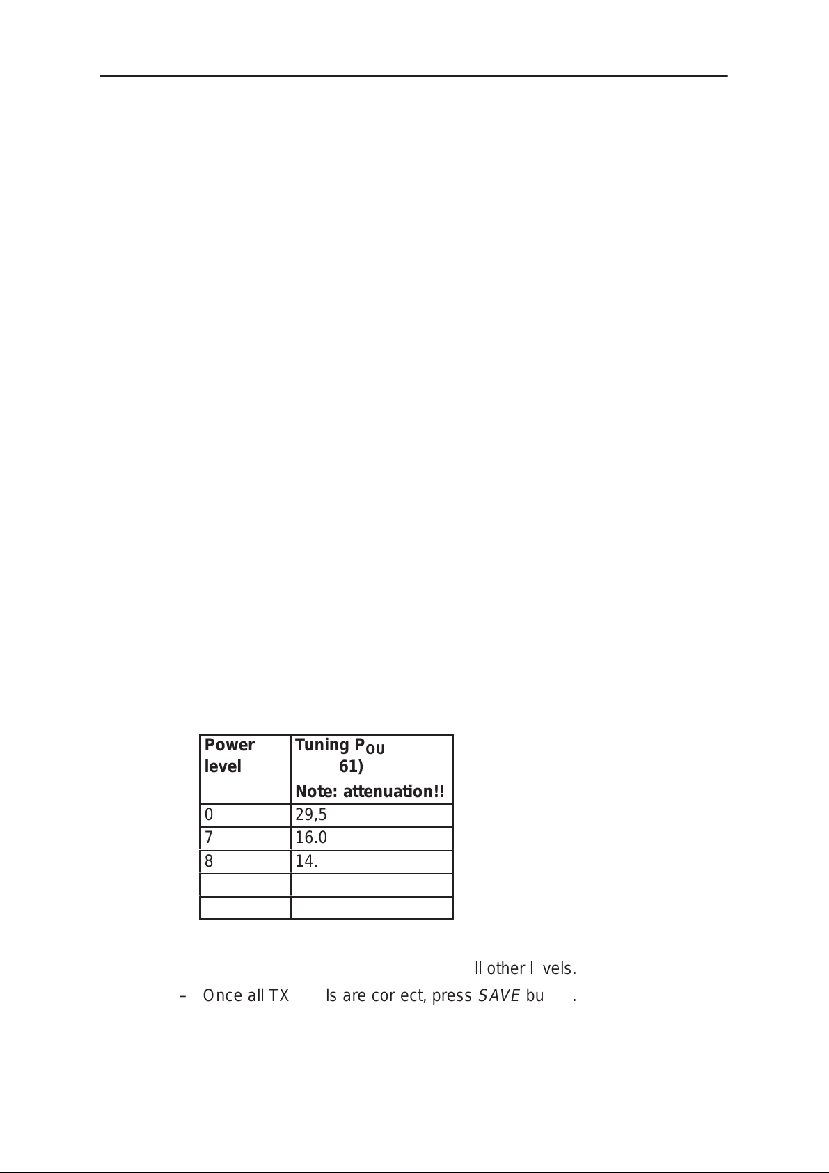
3. Tuning of Transmitter Power Levels
This adjustment loads the power levels of the phone transmitter into the
EEPROM. When doing this, a pulse power meter or spectrum analyzer
must be used.
– Adjust spectrum analyzer centre frequency to 1880 MHz, Span 0 Hz,
Res BW 3 MHz, Video BW 3MHz, Sweep time <20ms and Marker
peak.
Power levels programming:
– Set power supply voltage 8.4 V to service battery (or 3.6 V to jig).
– Connect pulse power meter or spectrum analyzer (with an attenuator if
needed) to the external antenna connector of the phone.
– Select
Tuning –> TX Power...
Technical Documentation
– Select tuning values from the PC’s memory, the phone’s EEPROM or
factory default values.
– Check that the channel is 661.
If it doesn’t, change it in RF Controls window.
– Increase base value by:
0.005 for SW version 3.X
0.012 for SW version 4.00 or later
– Adjust the power level (levels 0, 7, 8 and 15) by clicking the
+ and – buttons or and keys, and change levels with ↑
Power
ÁÁÁ
level
ÁÁÁ
0
7
8
15
Tuning P
БББББББ
(CH 661)
БББББББ
Note: attenuation!!
OUT
/dBm
29,5
16.0
14.0
0
and ↓ keys.
Page 14
– Press
Calculate
button to calculate all other levels.
– Once all TX levels are correct, press
SAVE
button.
Original 06/98
Page 15

PAMS
NSB–1/3
Technical Documentation
4. Energy Management Calibration
– Select Tuning –> Energy Management Calibration
– Connect service battery to phone and dc cable
between phone and service battery
– Set supply voltage to 10.5 V
– Run calibrations separately or all at once
– Select calibrations:
Battery & charger default values
––––––––––––––––––––––––––––––––
– Select 1.Run Battery & charger default values
checkbox
Battery voltage
Tuning Instructions
–––––––––––––––
– Select 2.Battery voltage checkbox
Charger voltage
–––––––––––––––
– Select 3.Charger voltage checkbox
Battery size
––––––––––––
– Select 4.Battery size checkbox
Battery temperature
–––––––––––––––––––
– Select 5.Battery temperature checkbox
Charge current
––––––––––––––
– Select 6.Charge current
– Select Save without confirmation, if you don’t want
confirm all the selected calibration values before saving
– Run calibrations by pressing Run button
– Set supply voltage back to 8.4 V
Original 06/98
Page 15
Page 16

NSB–1/3
PAMS
Tuning Instructions
Technical Documentation
This page intentionally left blank.
Page 16
Original 06/98
 Loading...