

Page 1

PAMS Technical Documentation
NSW–1 Series Transceivers
Chapter 2
General Information and
NAM programming
Original 12/99
Page 2

NSW–1
PAMS
General Information and NAM programming
Technical Documentation
CONTENTS
Product Selection 2 – 3. . . . . . . . . . . . . . . . . . . . . . . . . . . . . . . . . . . . . . .
Handportables 2 – 3. . . . . . . . . . . . . . . . . . . . . . . . . . . . . . . . . . . . . . .
Desktop Option 2 – 4. . . . . . . . . . . . . . . . . . . . . . . . . . . . . . . . . . . . . .
Basic Car Kit (CARK–64) Options 2 – 6. . . . . . . . . . . . . . . . . . . . . .
Advanced Hands Free Car Installation (CARK–91) Options 2 – 7
Product List 2 – 8. . . . . . . . . . . . . . . . . . . . . . . . . . . . . . . . . . . . . . . . . . . .
Module list 2 – 9. . . . . . . . . . . . . . . . . . . . . . . . . . . . . . . . . . . . . . . . . . .
Standard Colour front covers 2 – 9. . . . . . . . . . . . . . . . . . . . . . . . . . .
Interconnection Diagram 2 – 10. . . . . . . . . . . . . . . . . . . . . . . . . . . . . .
External interfaces 2 – 10. . . . . . . . . . . . . . . . . . . . . . . . . . . . . . . . . . . .
System Connector 2 – 10. . . . . . . . . . . . . . . . . . . . . . . . . . . . . . . . .
RF–connector 2 – 12. . . . . . . . . . . . . . . . . . . . . . . . . . . . . . . . . . . . .
Battery contacts 2 – 13. . . . . . . . . . . . . . . . . . . . . . . . . . . . . . . . . . . .
Page No
Technical Specifications 2 – 14. . . . . . . . . . . . . . . . . . . . . . . . . . . . . . . . .
General Specifications of Transceiver NSW–1 2 – 14. . . . . . . . . . . .
Nokia NSC–3*/NSW–3* NAM programming instructions 2 – 15. . . . .
Menu Driven Easy NAM Programming 2 – 15. . . . . . . . . . . . . . . . . .
Complete NAM Programming Instructions 2 – 16. . . . . . . . . . . . . . .
Access NAM Programming Mode: 2 – 16. . . . . . . . . . . . . . . . . . . .
MAIN MENU Selection 2 – 16. . . . . . . . . . . . . . . . . . . . . . . . . . . . . .
Programming NAM’s 1 Through 3 2 – 16. . . . . . . . . . . . . . . . . . . .
Programming the Security Code: 2 – 17. . . . . . . . . . . . . . . . . . .
Programming Emergency numbers: 2 – 17. . . . . . . . . . . . . . . .
Serial Number (ESN): 2 – 17. . . . . . . . . . . . . . . . . . . . . . . . . . . .
Programmed: (Date the phone is first programmed) 2 – 17. .
Exiting NAM Programming: 2 – 18. . . . . . . . . . . . . . . . . . . . . . .
Field test: 2 – 18. . . . . . . . . . . . . . . . . . . . . . . . . . . . . . . . . . . . . . .
Programming PSIDS and RSIDS: 2 – 18. . . . . . . . . . . . . . . . . . . .
Page 2 – 2
Original 12/99
Page 3
PAMS
NSW–1
Technical Documentation
Product Selection
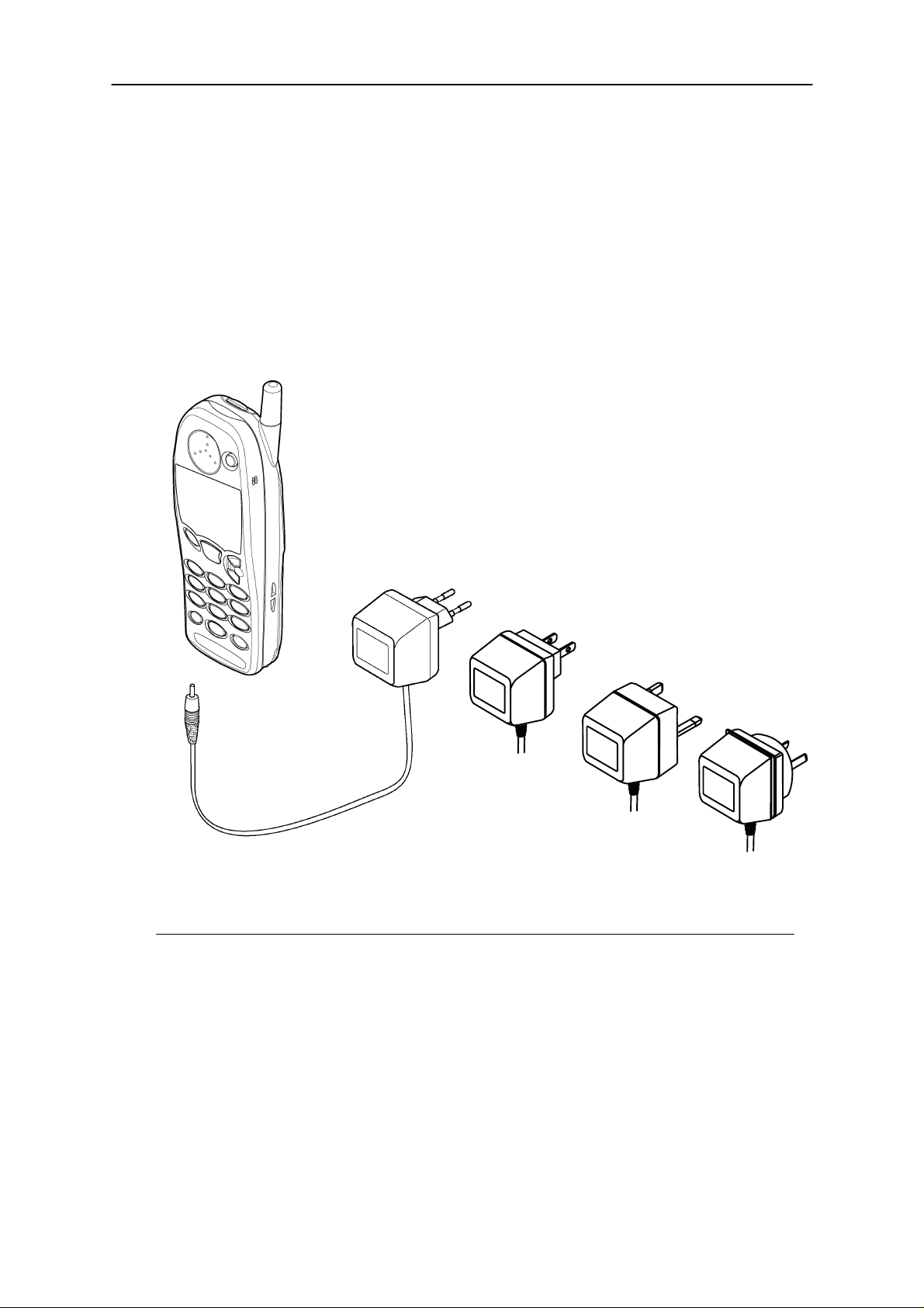
Handportables
The NSW–1 is a handportable dualband/dualmode mobile telephone for
the TDMA 800/1900 networks.
1.
General Information and NAM programming
ACP–7E
ACP–7U
ACP–7C
2.
3.
4.
5.
Item Name: Type code: Material code:
1. Transceiver (See Variant Section)
2. Standard battery (NiMH 900 mAh) BMS–2 0670203
3. AC Travel Charger
4. AC Travel Charger
5. AC Travel Charger
AC Travel Charger
6. AC Travel Charger
(Euro plug) 207–253 Vac ACP–7E 0675144
(US plug) 198–242 Vac ACP–7C 0675158
(UK plug) 207–253 Vac ACP–7X 0675145
(UK plug) 180–220 Vac ACP–7H 0675146
(Australia) 216–264 Vac ACP–7A 0675148
ACP–7X
ACP–7H
ACP–7A
6.
Original 12/99
Page 2 – 3
Page 4
NSW–1
PAMS
General Information and NAM programming
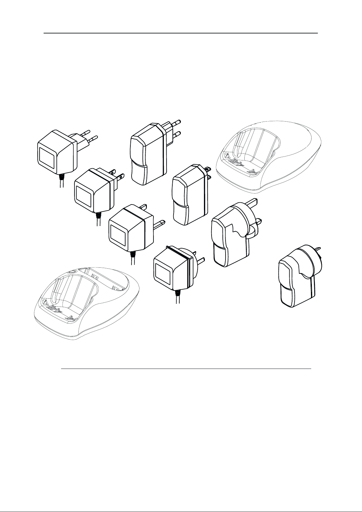
Desktop Option
The desktop option allows the user to charge the handportable and spare
battery from mains.
2.
6.
Technical Documentation
1b.
3.
7.
4.
1.
8.
5.
9.
Item Name: Type code: Material code:
1. Desktop stand DCH–9 0675179
2. Desktop stand DCH–8 0675174
3. AC Travel Charger
AC Travel Charger
4. AC Travel Charger
AC Travel Charger
5 AC Travel Charger
6. Fast Travel Charger
7. Fast Travel Charger
8. Fast Travel Charger
9. Fast Travel Charger
(US plug) 108–132 Vac ACP–7U 0675143
(US plug) 198–242 Vac ACP–7C 0675158
(UK plug) 207–253 Vac ACP–7X 0675145
(UK plug) 180–220 Vac ACP–7H 0675146
(Australia) 216–264 Vac ACP–7A 0675148
(Euro plug) 90–264 Vac ACP–9E 0675149
(US plug) 90–264 Vac ACP–9U 0675151
(UK plug) 90–264 Vac ACP–9X 0675150
(Australia) 90–264 V ac ACP–9A 0675152
Page 2 – 4
Original 12/99
Page 5
PAMS
NSW–1
Technical Documentation
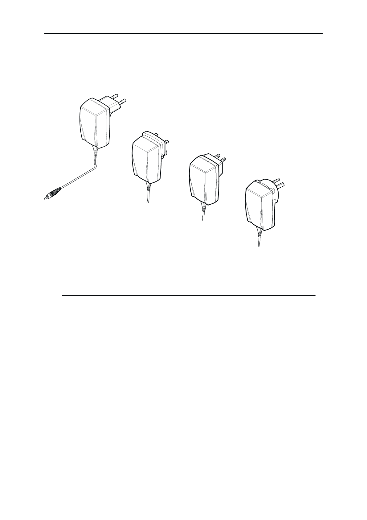
ACP–8E
ACP–8K
10.
General Information and NAM programming
ACP–8X
ACP–8U
ACP–8C
ACP–8A
11.
12.
13.
Item Name: Type code: Material code:
10. Performance Travel Charger (Euro plug) 90–264 Vac ACP–8E 0675195
10. Performance Travel Charger
11. Performance Travel Charger
12. Performance Travel Charger
12. Performance Travel Charger
13. Performance Travel Charger
(Korea plug) 90–264 Vac ACP–8K 0675119
(UK plug) 90–264 Vac ACP–8X 0675197
(US plug) 90–264 Vac ACP–8U 0675196
(China plug) 90–264 Vac ACP–8C 0675211
(Australia plug) 90–264 V ac ACP–8A 0675214
Original 12/99
Page 2 – 5
Page 6
NSW–1
PAMS
General Information and NAM programming
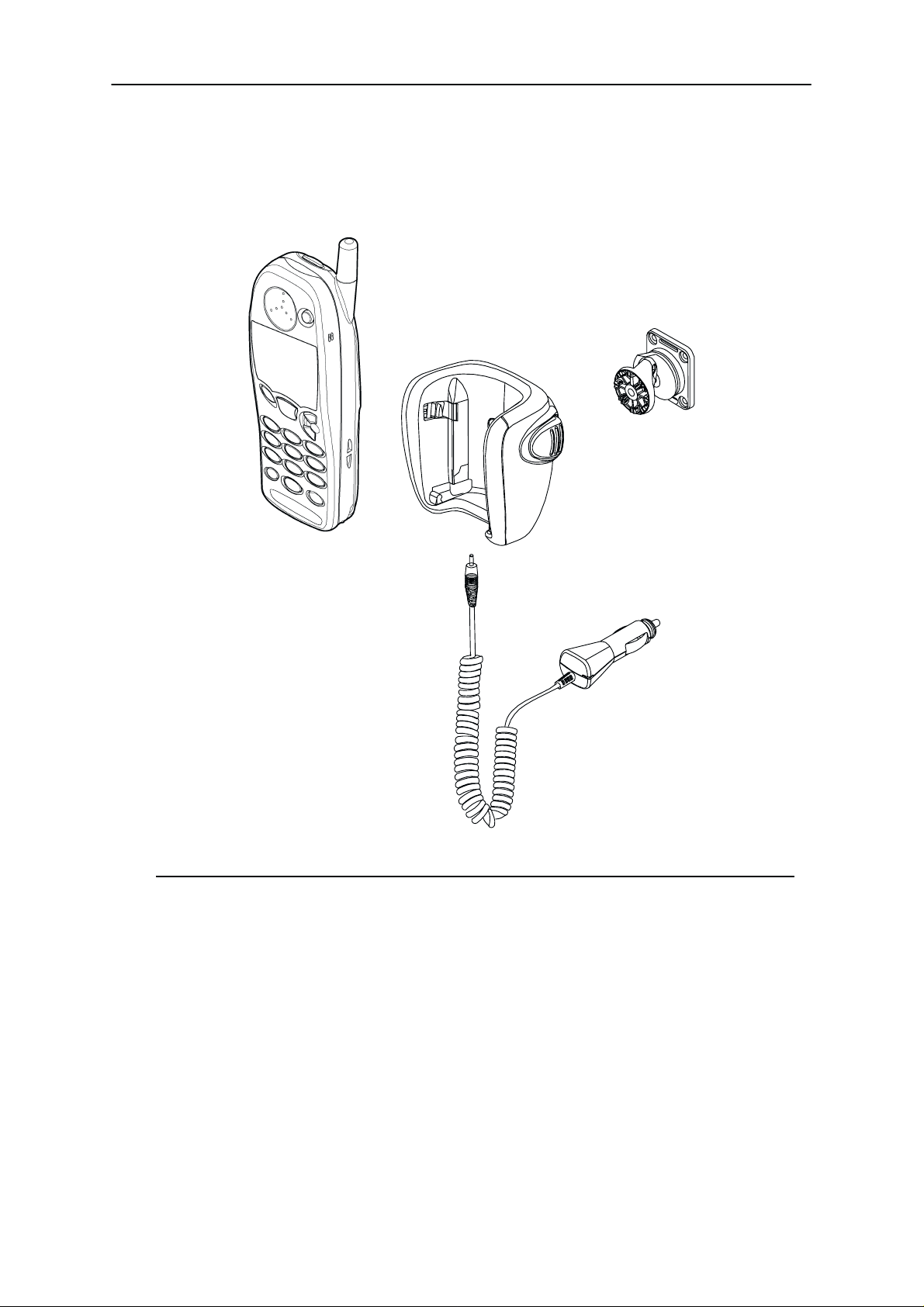
Basic Car Kit (CARK–64) Options
1.
2.
Technical Documentation
4.
3.
Item Name: Type code: Material code:
1. Transceiver (See variant Appendices)
2. Mobile Holder MBC–1 0700060
3. Cigarette Lighter Charger LCH–9 0657120
4. Swivel Mount HHS–9 0620037
Page 2 – 6
Original 12/99
Page 7

PAMS
NSW–1
Technical Documentation
General Information and NAM programming
Advanced Hands Free Car Installation (CARK–91) Options
7.
8.
3.
2.
1.
6.
5.
4.
Item Name: Type code: Material code:
1. Transceiver (See variant Appendices)
2. Mobile Holder MCC–1 0620043
3. Hands Free Unit HFU–2 0694049
4. Hands Free Microphone HFM–8 0690016
5. Hands Free Speaker HFS–12 0692008
6. Power Cable PCH–4J 0730055
7. Swivel Mount HHS–9 0620037
8. Mounting Plate MKU–1 0620036
Original 12/99
Page 2 – 7
Page 8

NSW–1
PAMS
General Information and NAM programming
Product List
Unit/type: Product code:
Transceiver NSC–1 See variant
Slim Battery BLS–2 900 mAh 0670206
Standard Battery BMS–2 900 mAh 0671323
Standard Battery BMS–2S 900 mAh NiMH 0670225
Vibrator Battery BMS–2V 900 mAh + 0670204
Extended Battery BLS–4 1500 mAh 0670207
AC Travel Charger ACP–7E (EUR) 207–253 Vac 0675144
AC Travel Charger ACP–7U (US) 108–132 Vac 0675143
AC Travel Charger ACP–7C (US) 198–242 Vac 0675158
AC Travel Charger ACP–7X (UK) 207–253 Vac 0675145
Technical Documentation
Appendixes
AC Travel Charger ACP–7H (UK) 180–220 Vac 0675146
AC Travel Charger ACP–7X (AUS) 216–264 Vac 0675148
Fast Travel Charger ACP–9E (EUR) 90–264 Vac 0675149
Fast Travel Charger ACP–9U (US) 90–264 Vac 0675151
Fast Travel Charger ACP–9X (UK) 90–264 Vac 0675150
Fast Travel Charger ACP–9A (AUS) 90–264 Vac 0675152
Performance Travel Charger ACP–8E (EUR)
90–264 Vac
Performance Travel Charger ACP–8K (KOR)
90–264 Vac
Performance Travel Charger ACP–8X (UK)
90–264 Vac
Performance Travel Charger ACP–8U (US)
90–264 Vac
Performance Travel Charger ACP–8C (CHINA)
90–264 Vac
Performance travel Charger ACP–8A (AUS)
90–264 Vac
0675195
0675199
0675197
0675196
0675211
0675214
Page 2 – 8
Cigarette Lighter Charger LCH–9 0675174
Desktop Stand DCH–9 0675174
Desktop Stand DCH–8
Mobile Holder MBC–1 0700060
Mobile Holder MCC–1 0620043
Handsfree Unit HFU–2 0694049
Original 12/99
Page 9

PAMS
NSW–1
Technical Documentation
Power Cable PCH–4J
General Information and NAM programming
0730055
HF Microphone HFM–8 0690016
HF Speaker HFS–12 0692008
Mounting Plate MKU–1 0620036
Swivel Mount HHS–9 0620037
Headset HDC–9 0694053
Headset HDC–9P 0694063
Belt Clip BCH–12 0720098
External Antenna Cable XRC–1 0730103
External Antenna Cable XRC–2 0730180
Module list
Name of module Type code Material code Notes
Basic transceiver NSW–1 0501948 Basic TR and recess for logo
plate
– System/RF module UT4S 0201301
– User interface module UE4S 0201360
– Mechanics assembly parts MNSW1 0261802 Common parts for NSW–1
– A cover assembly parts 9456243 Night blue, Recess for Logo La-
bel
– Window assembly parts 9457839
– Antenna 0660167
– Keymat 9790318
– Software module ( Basic SW
)
0240647 On flash memory
Standard Colour front covers
Colour : Part code:
Tango Orange 0261857
Antiqua Red 0261858
Gheko Green 0261859
Bermuda Blue 0261860
Dolphin Blue 0261861
Original 12/99
Page 2 – 9
Page 10

NSW–1
PAMS
General Information and NAM programming
Technical Documentation
Interconnection Diagram
10 9
Keypad Display
User Interface
Module
UE4S
28
2
Earpiece
4
Antenna
1
System
Connector
(including Mic)
Connector
Battery
System/RF
Module
UT4S
3 + 36+2
2
Charger
RF
External interfaces
System Connector
System connector provides
– 9 contact pads
– 3 for charging ( +, – and charging control )
– 6 for accessory interface (those are also for IBI–connection;
Page 2 – 10
Original 12/99
Page 11

PAMS
NSW–1
Technical Documentation
– 3–wires round DC–jack for the charging purposes
– microphone recess with 2 contact springs
– 2 NC–microphone channels in the connector body.
System connector is fixed to the phone body by 2 screws and to the PCB
by 2 solderable elements
B side view
Fixing pads (2 pcs)
General Information and NAM programming
connector bads are bent on the battery side)
8
1
7
14
IBI connector
(6 pads)
Engine PCB
Microphone
acoustic ports
DC Jack
Charger pads (3 pcs)
Bottom
connector (6 pads)
Cable locking holes (3 pcs)
Cavity for microphone
A side view
Figure 1. System connector.
Table 1. System connector signals.
Pin Name Function Description
1 V_IN Bottom charger contacts Charging voltage.
2 L_GND DC Jack Logic and charging ground.
3 V_IN DC Jack Charging voltage.
4 CHRG_CTRL DC Jack Charger control.
5 CHRG_CTRL Bottom charger contacts Charger control.
6 MICP Microphone Microphone signal, positive node.
7 MICN Microphone Microphone signal, negative node.
8 XMIC Bottom & IBI connectors Analog audio input.
Original 12/99
Page 2 – 11
Page 12

NSW–1
PAMS
General Information and NAM programming
Table 1. System connector signals. (continued)
9 SGND Bottom & IBI connectors Audio signal ground.
10 XEAR Bottom & IBI connectors Analog audio output.
11 MBUS Bottom & IBI connectors Bidirectional serial bus.
12 FBUS_RX Bottom & IBI connectors Serial data in.
13 FBUS_TX Bottom & IBI connectors Serial data out.
14 L_GND Bottom charger contacts Logic and charging ground.
Technical Documentation
DescriptionFunctionNamePin
RF–connector
The RF–connector is needed to utilize the external antenna with Car
Cradle. The RF–connector is located on the back side of the transceiver
on the top section. The connector is plug type connector with special mechanical switching.
Accessory side of connector
Part will be floating in
car holder
Figure 2. DCT–3 RF–connector
Phone side of connector
Page 2 – 12
Original 12/99
Page 13

PAMS
NSW–1
Technical Documentation
Battery contacts
General Information and NAM programming
Opening for
belt clip button
Battery contacts
Ringing
alert
System connector
Microphone
Charger connector jack
Pin Name Function Description
1 BVOLT Battery voltage Battery voltage
2 BSI Input voltage Input voltage
3 BTEMP Battery temperature indication
Phone power up
Battery power up
PWM to VIBRA BA TTERY
Input voltage
Input voltage
Output voltage
PWM output signal frequency
Type label
4 BGND Ground
Original 12/99
Page 2 – 13
Page 14

NSW–1
PAMS
General Information and NAM programming
Technical Documentation
Technical Specifications
General Specifications of Transceiver NSW–1
Parameter Unit
Cellular system TDMA/NADC 800/1900
RX frequency band 869.04 ... 893.97 MHz 1930.05 ... 1989.99 MHz
TX frequency band 824.04 ... 848.97 MHz 1850.01 ... 1909.95 MHz
Output power up to 600 mW
Duplex spacing 45 MHz / 80.04 MHz
Number of RF channels 831 / 1997
Channel spacing 30 kHz
Number of TX power levels 2 to 7 in analog, 2 to 10 in digital modes
Frequency control VCTCXO; AFC used in analog and digital modes
Receiver type Double conversion, common IF frequencies in all modes.
Modulator type I/Q modulation in digital modes, FM modulation in analog modes.
Page 2 – 14
Original 12/99
Page 15

PAMS
NSW–1
Technical Documentation
General Information and NAM programming
Nokia 5160/5120 cellular telephone (NSC–1*/NSW–1*) NAM programming instructions
All Nokia 5160/5120 cellular telephones (with software version 1.6 or later)
are capable of supporting both Random and Default authentication methods. The programmer must decide which form of A–Key is desired for use.
There are two methods to program the NAM described below.
If a RANDOM A–Key is desired for use, use the Easy NAM 1 programming
sequence.
If a DEF AULT A–Key is required, then use the Easy NAM 2 sequence. The
clear key can be used to correct mistakes.
Menu Driven Easy NAM ProgrammingRAMMING FOR NOKIA 6120/6
1. Turn on the phone and enter the Programming Access Code
*#6391# for NAM1 with a random A–key value
*#6392# for NAM2 with a default A–key value
2. Enter the 10 digit Area Code and Phone Number
and press the TALK key (or the ”OK” softkey in the display)
3. Enter the System ID Code (SID) supplied by the cellular service provider (1 –5 digit SID) and press the TALK key (or ”OK”
softkey in the display)
- Optional settings are Language and Lock Code (see below)
- Programming is completed
- The phone automatically powers off and then back on
NOTE:
Change the Lock code by adding a pound sign (£) and the new lock code
after the SID. (Example: 175£7788; Lock code = 7788).
Change the Language by adding a pound sign and new language code after
the code (Example: 175£0; Language = English).
Language Code: 0 (default) = English, 1 = French, 2 = Spanish, 3 = Portuguese.
Change the Lock Code and Language code by separating each set of numbers by a pound sign (Example: 175£7788£2; Where the SID = 00175, Lock
code = 7788, Language = Spanish).
Original 12/99
Page 2 – 15
Page 16

NSW–1
Á
Á
Á
Á
Á
Á
Á
Á
Á
Á
Á
Á
Á
Á
Á
Á
Á
Á
PAMS
General Information and NAM programming
Technical Documentation
Complete NAM Programming InstructionsnENNDPORTABLES
Access NAM Programming Mode:
1. Turn the phone on.
2. Enter the NAM access code.
Factory default is: * 3 0 0 1 # 1 2 3 4 5 #
3. If the screen to the right appears, the access code
was entered correctly.
If after several attempts you can not access
NAM programming, it is possible that the NAM 2
access code has been changed, or the phone
is in need of service.
MAIN MENU Selection
4. Press the [Scroll–Key] up or down until the indicator points at the desired
menu option. Select from the following:
NAM 1
SW version
NAM 2
Serial No.
5.Press the [Select] softkey to access the Sub–Menu from and of the above
Main Menu selections.
Programming NAM 1 and 2
6. If the value is incorrect, press the [Select] softkey and use the keypad to
enter new information.
Home
ÁÁÁ
system ID
NAM Status
Home SOC
ББББББ
(when unlocked)
Change Defaults (sub–menu from above)
Access method
Security
Field Test
Own
ÁÁÁ
number
Emergency
Alpha tag
ÁÁÁ
Local option
PSID/RSID
ÁÁÁÁ
lists
Primary paging
Change
ÁÁÁÁ
defaults
Page 2 – 16
(Enable/Disable)
БББББББ
Secondary paging
БББББББ
ch
Dedicated B cch
БББББББ
number
A–key code
ББББББ
Dedicated A cch
ББББББ
Overload class
ББББББ
ББББББ
Dedicated A cch
number
ББББББ
Group ID
ББББББ
БББББББ
channel
Dedicated B cch
БББББББ
SID alpha tag con-
БББББББ
trol
Original 12/99
Page 17

PAMS
NSW–1
Technical Documentation
7. Use the [OK] softkey to store the new information that has been entered.
8. Repeat steps 6 and 7 for the remaining NAM parameter options to be
viewed and/or changed.
9. To program other NAM, press [Back] to return to the Main Menu. Select
NAM 2 Once the Home System ID and Own number are programmed, the
phone will automatically set the NAM Status to enabled.
Programming the Security Code:
10. From the Main Menu, use the scroll keys to select the “Security” Sub–
Menu, press [Select] and the current 5–digit security code will appear in the
display. Default is 12345
1 1. If you wish to change the Security Code at this time, use the numeric keys
to enter the new value.
12. Press the softkey [OK] to store changes. Note: The Lock Code will be
automatically changed to the last 4 digits of the new Security Code.
General Information and NAM programming
Programming Emergency numbers:
13. From the Main Menu use the scroll key to select the ”Emergency” Sub–
Menu, press the [Select] softkey to access the emergency numbers.
Emergency number 1 (911)
Emergency number 2 (*911)
Emergency number 3 (None)
14. If you wish to change the displayed value, use the scroll key to select
the emergency number you wish to change and press [Select]. Then use the
numeric keys to enter the new values
15. To save the value, press the softkey [OK].
16. Press [Back] to exit the menu.
Serial Number (ESN):
17. From the Main Menu, use the scroll key to display the “Serial No.” or ESN
of the phone.
18. Press [Back] to exit the menu.
Programmed: (Date the phone is first programmed)
19. From the Main Menu, use the key to display the “Programmed” menu.
20. Press [Select] and enter a four digit number that corresponds to the
month and year the phone is sold. Example (mmyy)
NOTE: This menu location can be programmed only one time. Once
the date has been entered it can not be changed. Any attempt to enter the
Original 12/99
0199 = January 1999, 0401 = April 2001.
Page 2 – 17
Page 18

NSW–1
PAMS
General Information and NAM programming
menu once it has been programmed will receive a short beep and the message “Date already saved”.
Exiting NAM Programming:
21. To exit the NAM programming mode, turn the phone off and leave it off
for five seconds.
Field test:
The Field Test Display Mode is used to investigate how the phone and the
cellular network are interfacing together.
The Field Test Display Mode reports valuable information about the signal
strength, battery charging status, cellular state and encryption status.
The information is organized to display information relating to Analog Control
Channels, Digital Control Channels, Analog Voice Channels, and Digital
V oice channels. All the information provided in this display is in accordance
with IS–136.
Technical Documentation
To activate the Field Test Display Mode you must be in NAM programming.
Instructions for entering NAM programming are on the previous pages.
From the Main Menu use the scroll key to display the ”Field test” menu and
press the [Select] softkey.
Use the Scroll key to select “Enable” and press the [OK] softkey.
Turn the 5160/5120 off then back on. The FIELD TEST display will begin au-
tomatically after wake–up as long as the user does not enter any characters
into the display.
Scroll through the 6 different displays using the scroll key.
T o disable the FIELD TEST mode. Return to NAM programming and disable
the function under the FIELD TEST menu.
Programming PSIDS and RSIDS:
The Nokia 5160/5120 provides the option to program Private (PSIDs) and
Residential (RSIDs) System ID’s as prescribed by IS–136. The PSID /
RSID list is programmed to support system selection / re–selection processes, and SID display functions. The Nokia 5160/5120 product will
support up to 15 different Private or Residential Systems. These instructions allow a person to program 5 of the 15 available locations. The other
10 locations are reserved to ensure locations are available for automatic
programming.
Using the NAM programming menu to program the PSID / RSID is just
one of several ways that this information can be programmed. The phone
also supports automatic programming of the PSID / RSID values via registration accept message from a Public & Private system, manually
prompting with System Scan sub–menu option “New Search”, or via Over
Page 2 – 18
Original 12/99
Page 19

PAMS
NSW–1
Technical Documentation
the Air Programming. Follow these instructions to program the PSID /
RSID lists.
1. Enter the NAM programming menu and select NAM 1 (or the desired
NAM). (Note: PSID / RSID is currently only available in the NAM 1
location. PSID / RSID locations for NAM 2 are reserved for future use.)
2. Use the scroll key to display “PSID / RSID LISTS” then press [Select].
3. Use the scroll key to select the PSID / RSID 1 or the desired PSID / RSID
(1 through 5). Press the [Select] softkey.
4. Each list contains:
System type: Select Private or Residential system type.
PSID / RSID: System ID of the Private or Residential system.
Indicates which PSID / RSID the mobile will respond to.
Connected system ID: Connected System ID. The SID that the PSID /
RSID is connected to.
Alpha tag: The name of the Private or Residential SID that will be dis-
played when the phone uses the PSID / RSID. The micro system can over–
write the alpha tag once the phone is using the system with its network
broadcast name.
General Information and NAM programming
Operator code (SOC): (SOC) This is the System Operator Code.
US
AWS = 2049,
Canada
Rogers Cantel Inc. = 2050,
Bell South Cellular = 2051,
Southwestern Bell Mobile Systems = 004,
Vanguard = 007,
Century Cellunet = 008,
Pacific Telecom Cellular = 009,
Midwest Wireless Communications = 010.
These (inter)national SOC values are only an approximation from available
information. Please call Customer Service (888–Nokia–2U) with corrections.
Country code: Enter the Country Code of the PSID / RSID.
Public service profiles: Contains up to 4 channel and color code values
for each private or residential system. This information is necessary to initiate scanning for the Private or Residential System.
Private operating frequencies: Enter the channel number(s) of the
private system. The parameters allow for up to 4 channels per PSID / RSID.
Original 12/99
Page 2 – 19
Page 20

NSW–1
PAMS
General Information and NAM programming
Technical Documentation
This page intentionally left blank.
Page 2 – 20
Original 12/99
 Loading...