

Page 1
Customer Care Europe, Middel East & Africa NHL-8 Repairhints
SCCE Training Group Version 2.0 Approved
2003 Nokia Mobile Phones
CONFIDENTIAL
Date 11-08-2003
1 (13)
Repair Hints
Service-Level 3 & 4
3650
© NMP 2003
NHL-8
Checked by: SCCE
Approved by: Training Group
Page 2
CONFIDENTIAL
2 (13)
Customer Care Europe, Middel East & Africa NHL-8 Repairhints
SCCE Training Group Version 2.0 Approved
2003 Nokia Mobile Phones
Date 11-08-2003
GENERAL
- How to use this document
Put the colored schematics behind this manual.
Now you are able to follow these specifications with graphical layouts and it is easier for you to find the components
and measuring points.
- Component characteristics
Some components contain important data such as tuning values or security data; therefore several steps described are
only feasible if you are able to reflash/ realign the phone and/or rewrite IMEI/SIMlock in certain cases. Please pay
attention to separate notes.
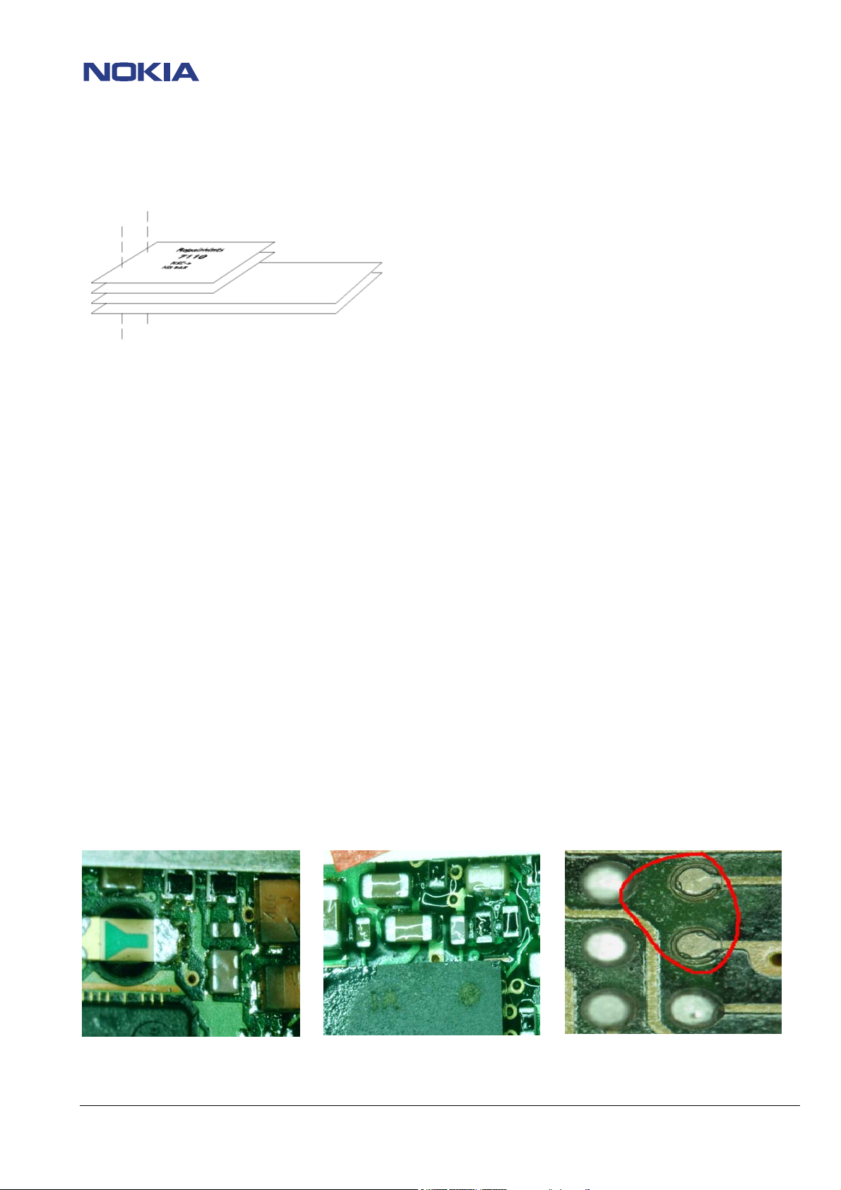
- Broken balls, µBGAs
All replaceable (not underfilled) µBGA components must be renewed after removing. Reflow with uncontrolled hot-air
fan is strictly forbidden! µBGA must only be soldered with NMP approved µBGA rework machines (e.g. Zevac/ OK-Metcal/
Martin) to get durable soldering joints. It is also not recommended only to reflow the old µBGA using a µBGA rework
station! Always remove camera module I012 from PWB before starting any rework!
After removing a µBGA check soldering points; if necessary rework oxidated solderings (broken balls) carefully by
tinplating these areas with few flux and a hot soldering iron. Before placing a new component remove the tin and
clean the PWB; e.g. with help of solder wick and flux cleaner such as “Kontakt LR”.
Use only recommended flux type and an appropriate amount of it – avoid drowning the PWB in flux as this will result in
additional faults!
“rework” done with uncontrolled hot-air PWB drowned in flux oxidized pads
© NMP 2003
Checked by: SCCE
Approved by: Training Group
Page 3
CONFIDENTIAL
3 (13)
Customer Care Europe, Middel East & Africa NHL-8 Repairhints
SCCE Training Group Version 2.0 Approved
2003 Nokia Mobile Phones
Date 11-08-2003
- PWB handling & cleaning
To avoid damages of PWB and/ or components through electrostatic discharging, handle the module in
ESD protected areas only (as shown on next page). When handling PWBs outside an ESD-bag always wear ESDwristbands, which must be connected to earth bonding point, and gloves to avoid corrosion and fingerprints. Damage
by electrostatic discharge often leads to a module not failing directly but after a short period of time!
For cleaning use only appropriate materials, do not use scratching or rubbing tools. Useful tools for cleaning are flux
cleaners such as “Kontakt LR” or “Electrolube FLU” in connection with ionized compressed air (see also General SB 163).
For shield disassembling or any other rework on the PWB always place the PWB into the rework jig MJS-93 (NMP-code
0770524) to prevent damaging e.g. connectors.
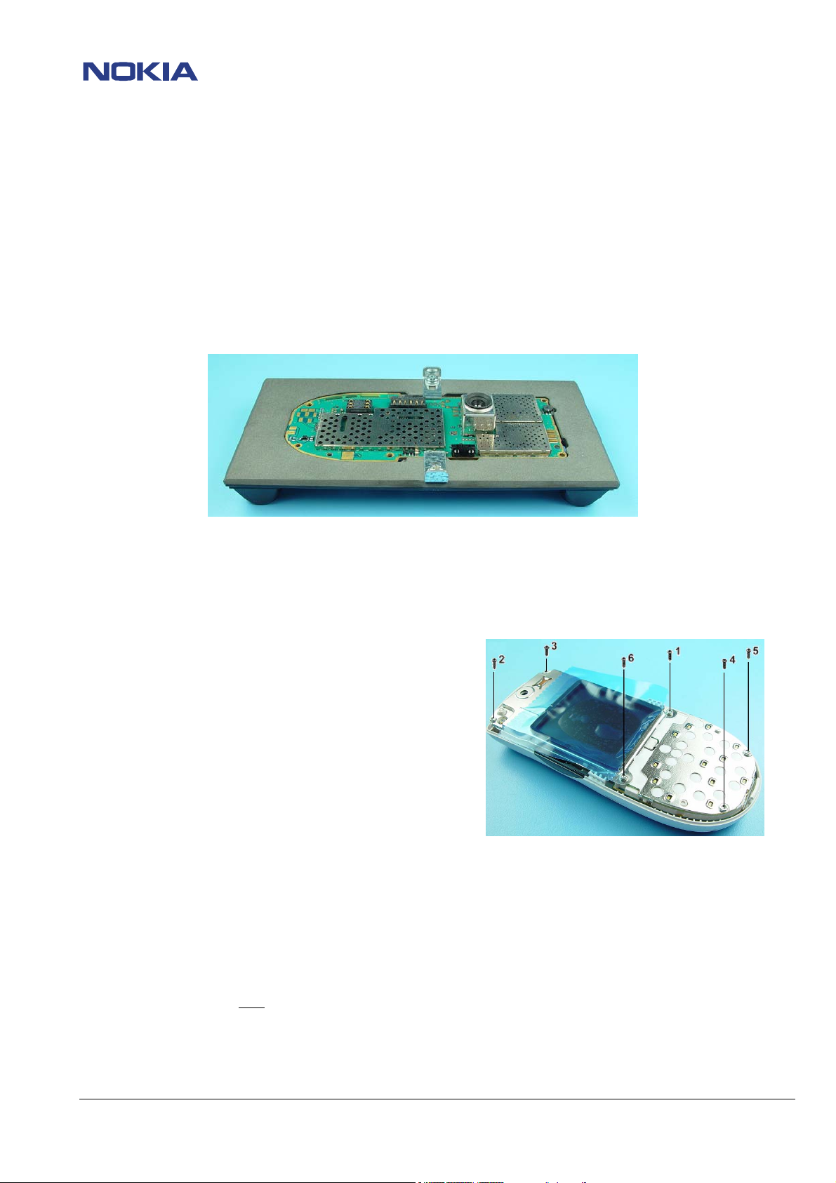
- Shieldings, screw torques
To avoid RF-problems it is not allowed to reuse any shielding that once has been removed from shielding frame.
Always use new shieldings after successful repair!
To tighten screws only use a torque screwdriver with a torque adjusted to 15Ncm. Notice tightening order that is
shown in the picture below; furthermore always use new screws!
- Realign after repair
Characteristics of replacement parts may vary.
To prevent additional faults after repair (e.g. low standby time, losing network etc.) it is necessary to retune phone
values after repair; but never try to cover up a fault by justing the phone settings!
- Fault report in fault log (Phoenix)
It is very important to report all repaired failures in fault log after finishing the complete phone repair.
The report content should only
In this case the report content should contain the symptom code that is given from the customer
e.g “Does not switch on”(2101) and the fault code“no fault found”(470).
If the symptom code from the customer is not the same as the observed symptom, use always the self-observed
symptom code.
contain the self-observed fault symptom, except “no fault found”.
© NMP 2003
Checked by: SCCE
Approved by: Training Group
Page 4
Customer Care Europe, Middel East & Africa NHL-8 Repairhints
SCCE Training Group Version 2.0 Approved
2003 Nokia Mobile Phones
CONFIDENTIAL
Date 11-08-2003
4 (13)
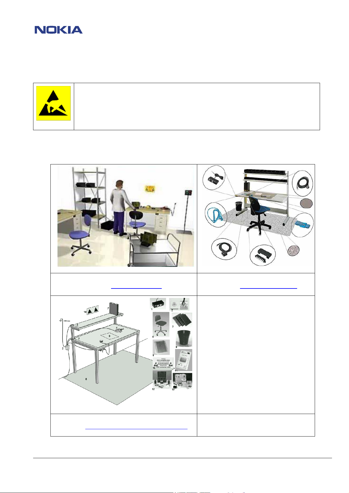
ESD PROTECTION REQUIREMENTS
Electrostatic discharge can easily damage the sensitive components
of electronic products. Therefore, every Service Partner has to take of
at least some precautions, such as ESD restricted area, floor, table,
covering, chair(s), shoes or wristbands.
For further information refer to the Partner Web Site document
“Service Partner Requirements”
example configuration of an epa-area
source: www.armeka.com
example workbench and testers
source: http://www.armekaengineering.com
example configuration of a workbench
source: www.warmbier.com
© NMP 2003
Checked by: SCCE
Approved by: Training Group
Page 5

CONFIDENTIAL
5 (13)
Customer Care Europe, Middel East & Africa NHL-8 Repairhints
SCCE Training Group Version 2.0 Approved
2003 Nokia Mobile Phones
Date 11-08-2003
Introduction
IMPORTANT:
This document is intended for use by authorized NOKIA service centers only.
The purpose of this document is to provide some further service information for NOKIA 3650 phones.
It contains a lot of collected tips and hints to find faults and repair solutions easily.
It also will give support to inexperienced technicians.
Saving process time and improving the repair quality is the aim of this document.
It is built up based on fault symptoms (listed in "Contents"), followed by detailed description for further analysis.
The document is to be used additionally to the service manual and other service information such as Service Bulletins.
For that reason it does not contain any circuit or schematic diagrams.
All measurements are made using following equipment:
Nokia repair SW: Phoenix version A9 2003.25.2.15
MCU SW: DP1.01 / MCU-SW 3.16
Nokia module jig: MJS-51
Docking station adapter: MJF-31
Digital multimeter: Fluke 73
Oscilloscope: Fluke PM 3380A/B
Spectrum Analyzer: Advantest R3131 with an analog probe
RF-Generator / GSM Tester: Rohde & Schwarz CMU 200
While every endeavour has been made to ensure the accuracy of this document, some errors may exist. If the reader
finds any errors, NOKIA should be notified in writing, using the following procedure:
Please state:
title of the document + issue number/date of publication.
page(s) and/or figure(s) in error.
Please send to: Nokia GmbH
Service & Competence Center Europe
Meesmannstr.103
D-44807 Bochum / Germany
Email: training.sace@nokia.com
Copyright © Nokia Mobile Phones.
This material, including documentation and any related computer programs is protected by copyright, controlled by
Nokia Mobile Phones. All rights are reserved. Copying, including reproducing, modifying, storing, adapting or
translating any or all of this material requires the prior written consent of Nokia Mobile Phones. This material also
contains confidential information, which may not be disclosed to others without the prior written consent of Nokia
Mobile Phones.
© NMP 2003
Checked by: SCCE
Approved by: Training Group
Page 6

CONFIDENTIAL
6 (13)
Customer Care Europe, Middel East & Africa NHL-8 Repairhints
SCCE Training Group Version 2.0 Approved
2003 Nokia Mobile Phones
Date 11-08-2003
Contents
PREFACE
Introduction 5
CHAPTER 1
CHAPTER 2
CHAPTER 3
CHAPTER 4
CHAPTER 5
CHAPTER 6
General 2
Zocus / Energy Management calibration 7
Phone hangs up / reboot 8
Phone does not switch on 9
Charging not possible 11
Audio problems 12
Change history 13
© NMP 2003
Checked by: SCCE
Approved by: Training Group
Page 7

Customer Care Europe, Middel East & Africa NHL-8 Repairhints
SCCE Training Group Version 2.0 Approved
2003 Nokia Mobile Phones
CONFIDENTIAL
Date 11-08-2003
7 (13)
Chapter 1: Zocus / Energy Management calibration
Zocus/Energy Management calibration is possible now with an assembled phone using the docking
station JBV-1 with docking station adapter MJF-31 (see also NHL-8 SB013). For calibration set the
supply voltage to +12Volt, furthermore connect SCB-3 DC-cable between docking station and phone.
A complete EM calibration (including Zocus calibration) has to be performed in case that the flash
circuit containing the tuning values has been exchanged or the flash content has been deleted with
the erase file.
Zocus calibration only is necessary, if Zocus N301 or the components on the sense input (R383/384,
C386) have been replaced.
If any other part of the charging circuit has been exchanged, you have to perform EM-calibration
without calibrating Zocus.
To calibrate only the Zocus device, open -> tuning -> EM calibration and tick the battery current box.
Please note that if there are no tuning values in the phone memory (all values zero, check by
ticking “Read from phone” button in EM calibration window), you will get a failure message if you
try to calibrate battery current. There are two possibilities to avoid this failure message:
- Start EM-calibration without Zocus calibration (i.e. battery current) and save the tuning
values by ticking on the “Save to phone” button. After that start EM-calibration again (this
time including battery current) and save all tuning values.
- Start with Zocus EM calibration instead of EM calibration; choose -> tuning -> Zocus_EM.
Fill in any value between 1 and 255 into the “Zocus_New_Cal:” box:
After that tick the “Close Charge Switch” button, then tick the “Write” button. Now close the
Zocus_EM window and return to the energy management calibration. All EM calibration steps
now should work without any failure message. After successful calibration press the “Save to
phone” button and close the energy management calibration window.
© NMP 2003
Checked by: SCCE
Approved by: Training Group
Page 8

CONFIDENTIAL
8 (13)
Customer Care Europe, Middel East & Africa NHL-8 Repairhints
SCCE Training Group Version 2.0 Approved
2003 Nokia Mobile Phones
Date 11-08-2003
Chapter 2: Phone hangs up / reboot
Pre-check
Try to switch on the phone with BL-5C battery inserted. The most common symptom is that the backlight is
switched on; then the Nokia logo appears for less than a second. After that the phone hangs up and the
display content disappears slightly.
It is also not possible to boot the phone in local mode using the docking station JBV-1 supplied with +12Volt!
Note that if the Nokia logo remains for more than one second on the display the root cause for the problem
is not the Permanent Memory Manager and the below described procedure will not solve the fault.
Applications installed by the end user are the most common reason for this problem. Try to initialize the
phone in local mode and use Phoenix SSW to format the user area of the flash circuit.
Repair instructions
Please note that it is usually not necessary to exchange any component!
To solve the reboot problem, download the file “CCSErasePPM.fia” from Partner Web Site section NHL-8/
software (see also NHL-8 SB012). Connect the phone via docking station JBV-1 to Phoenix SSW and open the
Flash menu. Choose the downloaded file to be flashed into the “Image File” section, leave the others blank
and start flashing. After successful flashing of the erase file, flash the latest version of phone software as
usual. While flashing you will be asked to “put power on and press OK”. If you do so and tick the OK button,
you often get a failure message “Changing phone´s operation mode failed. Do you want to retry?”. Ignore
this message and tick the “retry”-button, several times if necessary.
In some cases it might be necessary to repeat the whole procedure to get the phone working proper.
Please note that this procedure does not affect the user data, but it is necessary to rebuild IMEI / SIMlock
data; furthermore you have to perform all baseband- and RF-tunings.
If, however, it is anyway necessary to exchange a flash circuit, always keep in mind not to mix flash circuits
of different vendors: always replace Intel with Intel and AMD with AMD (see also NHL-8 SB014)!
© NMP 2003
Checked by: SCCE
Approved by: Training Group
Page 9

CONFIDENTIAL
9 (13)
Customer Care Europe, Middel East & Africa NHL-8 Repairhints
SCCE Training Group Version 2.0 Approved
2003 Nokia Mobile Phones
Date 11-08-2003
Chapter 3: Phone does not switch on
Pre-Check
First of all check the current consumption of the phone. If current is > 0.5A directly after connecting the
phone to the docking station, follow repair instructions:
o too high current consumption
If the current consumption is zero, follow repair instructions:
o mechanical faults
In all other cases follow the repair instructions
o electrical faults
Repair instructions
Too high current consumption
There are three main possibilities for this fault:
- Power amplifier N801 causes a short circuit to ground. To ensure that N801 is faulty you always should
remove both L805 and L808. If current is ok after removing these two components, you can be sure
that the power ampliefer is responsible for the fault.
Remember to realign TX tuning values after exchanging the power amplifer N801!
- UEM D190 causes the problem. Unfortunately there are no coils in the input lines for the baseband
regulators; only the RF regulators can be disconnected by removing coils Z300 – Z302.
Remember to perform baseband and RF calibrations; furthermore you have to rewrite IMEI and
SIMlock data to the phone after exchanging UEM D190!
- The PWB has been supplied with +12V in module jig with regulator switch in “bypass” mode.
Dependent on the capabilities of your power supply this results in a defect DC/DC-converter N261, a
defect HW-accelerator D103 and a defect Bluetooth module N430.
Mechanical faults
- Check mechanical appearance of battery connector I019. Exchange the part if the spring contacts are
bent, soiled or corroded.
© NMP 2003
Checked by: SCCE
Approved by: Training Group
Page 10

CONFIDENTIAL
10 (13)
Customer Care Europe, Middel East & Africa NHL-8 Repairhints
SCCE Training Group Version 2.0 Approved
2003 Nokia Mobile Phones
Date 11-08-2003
Electrical faults
Before exchanging any part of the phone, always check whether updating the phone software can solve
the problem!
In case updating the phone software cannot solve the fault, check voltage at power switch S130. In
unpressed state the voltage normally is 3.5 Volt. If you press the switch the voltage must decrease to 0 Volt;
otherwise you have to exchange the power switch S130.
If no voltage is measurable at the power switch in unpressed state this usually is caused by a defect UEM
D190.
If the power switch seems to work well, check that UEM D190 is working:
- Check battery voltage at C241, C243 and C300, furthermore at both sides of Z300 – Z302.
- Check whether sleepclock oscillator B190 is working: voltage at both sides of crystal D190 usually is
0.5VDC; signals measured with an oscilloscope should appear like this:
Figure 1: 32.768kHz at C196 Figure 2: 32.768kHz at C197
- Check whether the following voltages are measurable after pressing the power switch (at least for
some milliseconds): check VIO 1.8VDC at C198, VFlash1 2.78VDC at C194, VANA 2.78VDC at C242,
VR3 2.8VDC at C257, PURX 1.8VDC at J125, SLEEPX 1.8VDC at J124 and UEMRST (enables regulator for
VcoreA, check 1.8VDC at C263) 3.9VDC at R265. If only one of these voltages is missing check that there
is no short circuit on the line and exchange D190. In case all voltages are ok, try to perform SW-update.
A failure message C101 “Can´t set flashbus TXD line high” usually is sign for a defect UEM D190.
Remember that you have to rebuild IMEI and SIMlock data; furthermore you have to realign tuning values
after exchanging UEM D190!
© NMP 2003
Checked by: SCCE
Approved by: Training Group
Page 11

Customer Care Europe, Middel East & Africa NHL-8 Repairhints
SCCE Training Group Version 2.0 Approved
2003 Nokia Mobile Phones
CONFIDENTIAL
Date 11-08-2003
11 (13)
Chapter 4: Charging not possible
Pre-check
If charging the battery is impossible the first thing to do is to check whether charging is not possible only
occasionally /from time to time or if charging does not work permanently. In case the fault appears from
time to time only, follow the repair instructions:
o Mechanical faults
If charging does not work permanently, run energy management calibration. In case of any failure message
follow electrical repair instructions:
o Electrical faults
Repair instructions
Mechanical faults
In case charging is impossible only from time to time, especially check spring contacts of DC connector I021
and battery connector I019 if bent, soiled or corroded. Furthermore make sure that contact pads for
connectors on PWB are clean; if necessary clean them with an appropriate amount of alcohol. In no way use
any scratching or rubbing tools!
Electrical faults
The most common fault, if energy management calibration does not work, is a defect fuse F380. Check
resistance of fuse (must be 0 Ohm); replace part if necessary.
To ensure the correct functioning of phone run energy management calibration whenever having changed
a part in the charging circuit or when the flash circuit containing the tuning values has been exchanged!
© NMP 2003
Checked by: SCCE
Approved by: Training Group
Page 12

Customer Care Europe, Middel East & Africa NHL-8 Repairhints
SCCE Training Group Version 2.0 Approved
2003 Nokia Mobile Phones
CONFIDENTIAL
Date 11-08-2003
12 (13)
Chapter 5: Audio problems
Pre-check
In case of any audio fault in the phone, the best to define the fault is to make a call with the defect phone to
a properly working one. In case you can hear the speech of the proper working phone in the defect one but
not the other way round the signal path of the internal microphone is responsible for the fault.
The same procedure can be used to check the internal hands free speaker and the external audiopathes
XMIC and XEAR.
If the internal microphone does not work, follow repair instructions:
If the internal earpiece does not work, follow repair instructions:
Repair instructions
Internal microphone faulty
If the internal microphone does not work, check mechanical appearance of microphone I020, change part if
spring contacts are bent or soiled. Also make sure that contact pads for microphone on PWB are clean; if
necessary clean them with an appropriate amount of alcohol. In no way use any scratching or rubbing tools!
Internal earpiece faulty
Check mechanical appearance of internal earpiece I010, change part if spring contacts are bent or soiled.
Also make sure that contact pads for earpiece on PWB are clean, if necessary clean them with an appropriate
amount of alcohol. In no way use any scratching or rubbing tools! Resistance of earpiece normally is 32 Ohm.
o internal microphone faulty
o internal earpiece faulty
© NMP 2003
Checked by: SCCE
Approved by: Training Group
Page 13

CONFIDENTIAL
13 (13)
Customer Care Europe, Middel East & Africa NHL-8 Repairhints
SCCE Training Group Version 2.0 Approved
2003 Nokia Mobile Phones
Date 11-08-2003
Chapter 6: Change History
Originator Status Version Date Comment
TS Training
Group
Draft 0.1 19-05-2003 First Draft version
TS Training
Group
TS Training
Group
Approved 1.0 26-05-2003 First approved version
Approved 2.0 11-08-2003
Chapter “Zocus/EM calibration” added,
Chapter “Phone hangs up” improved with latest information
© NMP 2003
Checked by: SCCE
Approved by: Training Group
 Loading...