

Page 1

Customer Care Solutions
NHM-10 Series Transceivers
3 - Service Software
Issue 2 01/2004 Copyright 2003 Nokia Corporation Page 3-1
Company Confidential
Page 2

NHM-10 Company Confidential
3 - Service Software CCS Technical Documentation
Table of Contents
Description
Page No.
Service Software .......................................................................................... 5
Phoenix ................................................................................................... 5
Supported Operating Systems ................................................... 5
Hardware requirements for using Phoenix ............................ 5
Introduction ................................................................................... 5
Installing Phoenix ................................................................. 5
Uninstalling Phoenix ............................................................ 6
Data Packages ........................................................................ 6
Starting a session ......................................................................... 7
Concepts .................................................................................. 7
Selecting a product ............................................................... 7
Selecting a connection ........................................................ 7
Phoenix environment ........................................................... 7
Using components ................................................................ 7
Using profiles .......................................................................... 8
SW update flashing setup .................................................................. 8
FPS-8 Flash setup ......................................................................... 8
POS Flash concept ........................................................................ 9
Module Jig Flash concept ........................................................... 10
NHM-10 Phoenix installation instructions ........................... 10
FPS-8 to PC connection Setup instructions .......................... 11
FPS-8 activation ........................................................................... 11
Checking application SW version inside FPS-8 .................... 11
Reprogramming NHM-10 .................................................................. 13
Connecting cables ........................................................................ 13
Proceed as follows ........................................................................ 13
Settings backup/restore .............................................................. 13
Updating software ........................................................................ 14
Formatting user area ................................................................... 15
Restore settings ............................................................................ 15
Energy Management Calibration ..................................................... 15
Connections ................................................................................... 15
Phoenix Setup ................................................................................ 15
Calibration ...................................................................................... 15
Zocus calibration .......................................................................... 16
Phoenix Tuning ..................................................................................... 17
RF Tuning after repairs ................................................................ 17
RX Channel Select Filter calibration ........................................ 18
Page 3-2 Copyright 2004 Nokia Corporation Issue 2 01/2004
Company Confidential
Page 3

Company Confidential NHM-10
CCS Technical Documentation 3 - Service Software
Description
Page No.
RX Calibration (incl. VCXO calibration) .................................. 19
EGSM ....................................................................................... 20
GSM1900 (PCS) ..................................................................... 23
RX AGC limits ................................................................................. 25
RX Band filter response compensation ................................... 25
EGSM850 (EGSM) ................................................................. 25
Manual Tuning ................................................................ 26
GSM1900 (PCS) ..................................................................... 27
Manual Tuning ................................................................ 28
TX I/Q tuning .................................................................................. 29
EGSM (EGSM850) ................................................................ 29
GSM1900 (PCS) ..................................................................... 34
TX power tuning ............................................................................ 38
EGSM (EGSM850) ................................................................ 39
GSM1900 (PCS) ..................................................................... 40
Appendix 3-A NHM-10 - 3620 ................................................................ 42
Issue 2 01/2004 Copyright 2004 Nokia Corporation Page 3-3
Company Confidential
Page 4

NHM-10 Company Confidential
3 - Service Software CCS Technical Documentation
This page has been left blank intentionally
Page 3-4 Copyright 2004 Nokia Corporation Issue 2 01/2004
Company Confidential
Page 5

Company Confidential NHM-10
CCS Technical Documentation 3 - Service Software
Service Software
Phoenix
Phoenix is the new generation Service Software. It has been designed to meet the challenges in servicing modern cellular phone technology.
The Phoenix program has been built using component architecture. This means that the
actual program is small and most of the program’s functionality is divided into dynamically loaded modules (DLLs).
Supported Operating Systems
Windows 98, 2000, ME and NT 4.0 (SP4).
Hardware requirements for using Phoenix
Minimum:
Processor 233 MHz, RAM memory 64 MB, Disk space 50-100 MB.
Recommended for Windows 2000:
Processor 700 MHz, RAM memory 512 MB, Disk space 50-100 MB.
Introduction
This section briefly describes how to install the Phoenix software and includes some
basic information on how to use the program. For more detailed information, please refer
to Phoenix’s Help -files. Each feature in Phoenix has its own Help function, which can
be activated while running the program.
Press the F1 key or the feature’s Help-button to activate a Help -file.
Installing Phoenix
1. Download the latest release. Please contact your regional After Market Services point
for information on where to download the latest release.
Download and read the release notes, which have useful information on the software
version you are using.
2. Download the latest data packages for the products you will be using.
3. Before you start installing the program, check that
- the dongle is attached to parallel port. Contact your supervisor in order to obtain a
suitable dongle.
- you have administrator rights (Windows 2000 or NT only). This is required in order
to be able to install Phoenix.
4. Install Phoenix by executing the Phoenix installation package and follow the instructions on the screen.
Issue 2 01/2004 Copyright 2004 Nokia Corporation Page 3-5
Company Confidential
Page 6

NHM-10 Company Confidential
3 - Service Software CCS Technical Documentation
Initially the setup files are extracted into the file system.
Note: If the setup files are already extracted (left in the file system from previous installation) “Overwrite Protection” dialog appears. Always click "Yes to All" to overwrite the existing setup files.
5. The installation checks that the latest supported dongle driver version is installed. The
dongle driver is installed if there is no previous installation of the dongle driver or if the
installed dongle driver is older than the latest supported version.
Note: If the dongle driver is installed during installation, you need to reboot your PC and
restart
the installation after reboot.
Program files are stored under ” C:\Program Files\Nokia\Phoenix” (default).
6. Install the data package by executing the installation package and follow the instructions on the screen.
The data packages will create product specific directories under the installation directory.
Data files are stored under ” C:\Program Files\Nokia\Phoenix” (default).
Uninstalling Phoenix
If you need to remove Phoenix Service Software from your computer:
1. Make sure that the dongle is attached (unregistration).
2. Go to the Control Panel and select Add/Remove Programs.
3. Select NHM-10 RELEASE for uninstallation and click Add/Remove.
4. Click OK to remove the application
You may have to reboot your PC after uninstallation.
Note: If you have different product packages installed, the components are uninstalled only if
they are not included in other product packages.
Data Packages
Data Packages (DP) is a name for a helpful feature in the Phoenix software. This type of
feature provides a flexible way of distributing and installing Phoenix and its data files.
All product-specific data is separated from the program code and installed separately.
This means that the installation is performed in at least two steps.
Each product will have its own Data Package (DP). The FPS-8 flashing equipment also has
its own package.
Page 3-6 Copyright 2004 Nokia Corporation Issue 2 01/2004
Company Confidential
Page 7

Company Confidential NHM-10
CCS Technical Documentation 3 - Service Software
Starting a session
Concepts
In the Phoenix context, Product means the cellular phone attached to a PC. More specifically, it is a particular type of phone.
Connection means the type of cable used to attach the phone to the port to which the
other end of the cable is attached.
Selecting a product
Many of Phoenix’s features are product-specific. It is, therefore, mandatory to choose the
product you will be working on at the beginning of the session.
Select the menu item File - Choose Product. You will be presented with a list of available
products.
After the product selection, you will see an additional menu item on the main menu. If
you take a look at the available menu items, you will see that their number has
increased.
Selecting a connection
The connection defines the cable and the communications port that will be used when
connecting to the phone.
1. Active connections are listed in the toolbar’s Connection pull-down menu. You should
make sure that the connection is correct before using the software. Change it, if necessary.
In case the connection is the wrong, you need to create a new one.
2. Select Settings from the pull-down menu .
3. Select Add in the Connection List Dialog and in fill the relevant fields in the Connec-
tion setup dialog.
Phoenix environment
You can configure the program’s main toolbar and the product or tool -specific options
to your liking.
You can control which toolbars are visible by selecting View and Toolbars from the pulldown menu. The visible toolbars are marked with a check.
The rest of the options are product or tool -specific. The tool-specific options are set
using the associated toolbar.
Using components
When working with Phoenix, each task generally has its own component that will perform the task. The first thing, therefore, is to open the desired component.
Issue 2 01/2004 Copyright 2004 Nokia Corporation Page 3-7
Company Confidential
Page 8
NHM-10 Company Confidential
3 - Service Software CCS Technical Documentation
Opening a component means that you open a tool window within Phoenix. When this
window is opened, Phoenix also opens a toolbar for it and adds component-specific
menu items in the View menu.
Using profiles
A Profile is a useful feature in the software. Product, connection and currently open
components can be stored into a permanent storage (a disk file called profile, *.nmp) for
later retrieval.
Opening and saving profiles is done via menu commands found in the File menu. Select
Open Profile and Save Profile.
Since profiles are stored into a disk file with the user-defined name, there can be multiple profiles for different repeated tasks.
SW update flashing setup
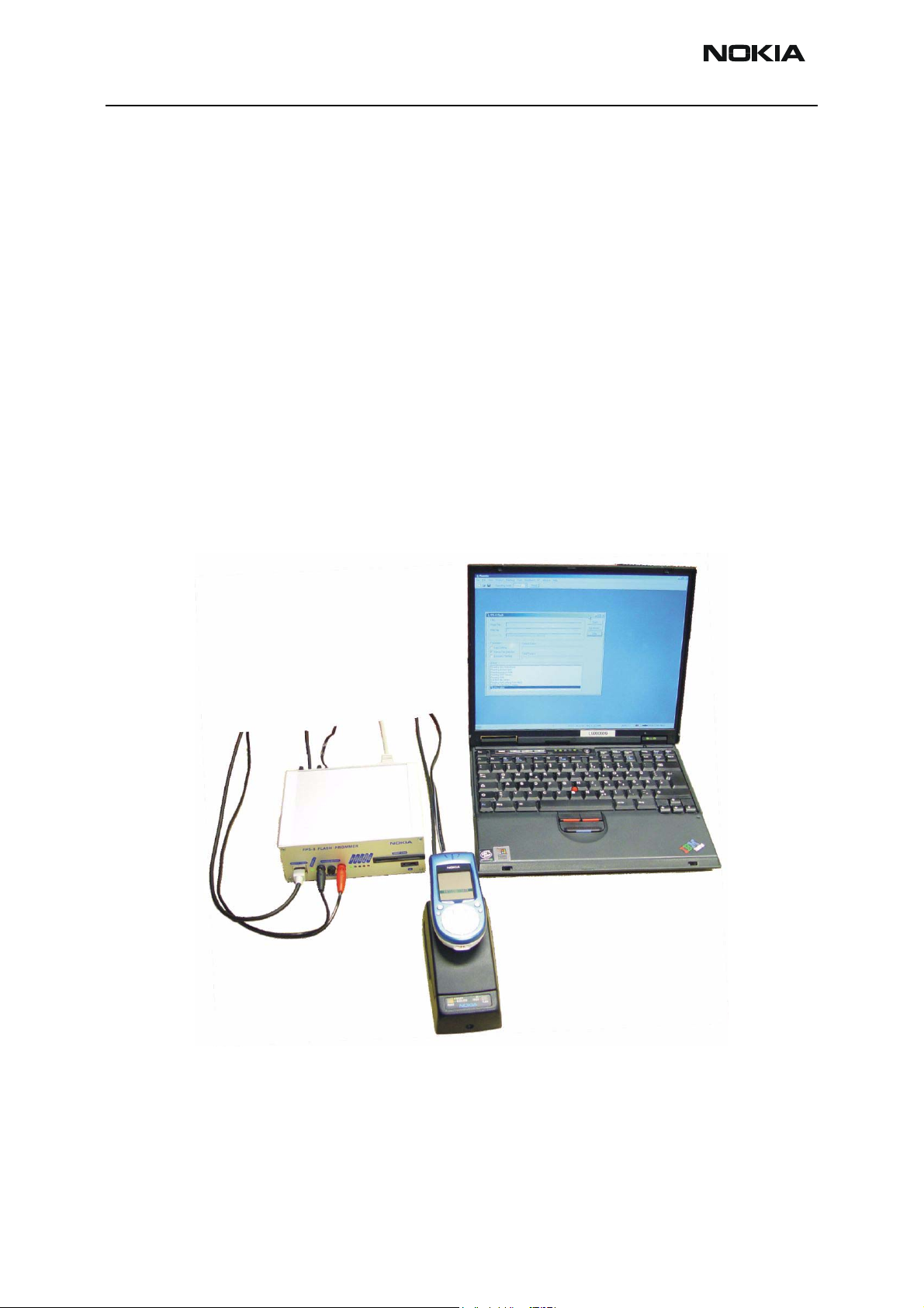
FPS-8 Flash setup
The following equipment is required for 3600/3620 (NHM-10) AMS SW update, when
connecting NHM-10 to PC with FPS-8:
Page 3-8 Copyright 2004 Nokia Corporation Issue 2 01/2004
Company Confidential
Page 9
Company Confidential NHM-10
CCS Technical Documentation 3 - Service Software
Item Description Type Code
1 Docking station adapter MJF-31 (use with JBV-1) 0770478
1a Point of Sales flash loading adapter FLA-48 0770582
2 Power cable PCS-1 0730012
3 Power cable FLC-2 0730185
4 Modular cable XCS-4 0730178
5 Flash prommer box sales pack FPS-8 0080321
6 Printer cable AXP-8, incl in FPS-8 sales pack
7 D9 – D9 cable AXS-4 , incl in FPS-8 sales pack 0730090
8 Software protection key PKD-1 0750018
9 AC Charger, incl in FPS-8 sales pack 0680032
10 SRAM Module (2 pcs needed
inside FPS-8)
SF12 0080346 (Code includes
one SRAM module)
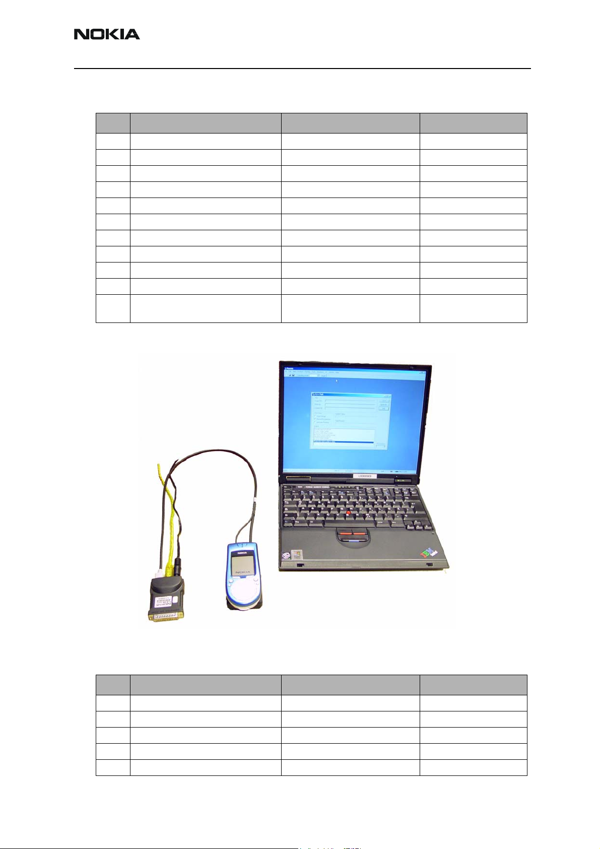
POS Flash concept
The following equipment is required for 3600/3620 (NHM-10) AMS SW update, at point
of salewhen connecting NHM-10 to PC with FLS-4:
Item Description Type Code
1 Point of Sales flash loading adapter FLA-48 0770582
2 Service cable XCS-1 0730218
3 FLS-4S sates pack for E & A FLS-4S 0080541
4 FLS-4S sates pack for APAC FLS-4S 0080542
5 FLS-4S sates pack for US FLS-4S 0080543
Issue 2 01/2004 Copyright 2004 Nokia Corporation Page 3-9
Company Confidential
Page 10
NHM-10 Company Confidential
3 - Service Software CCS Technical Documentation
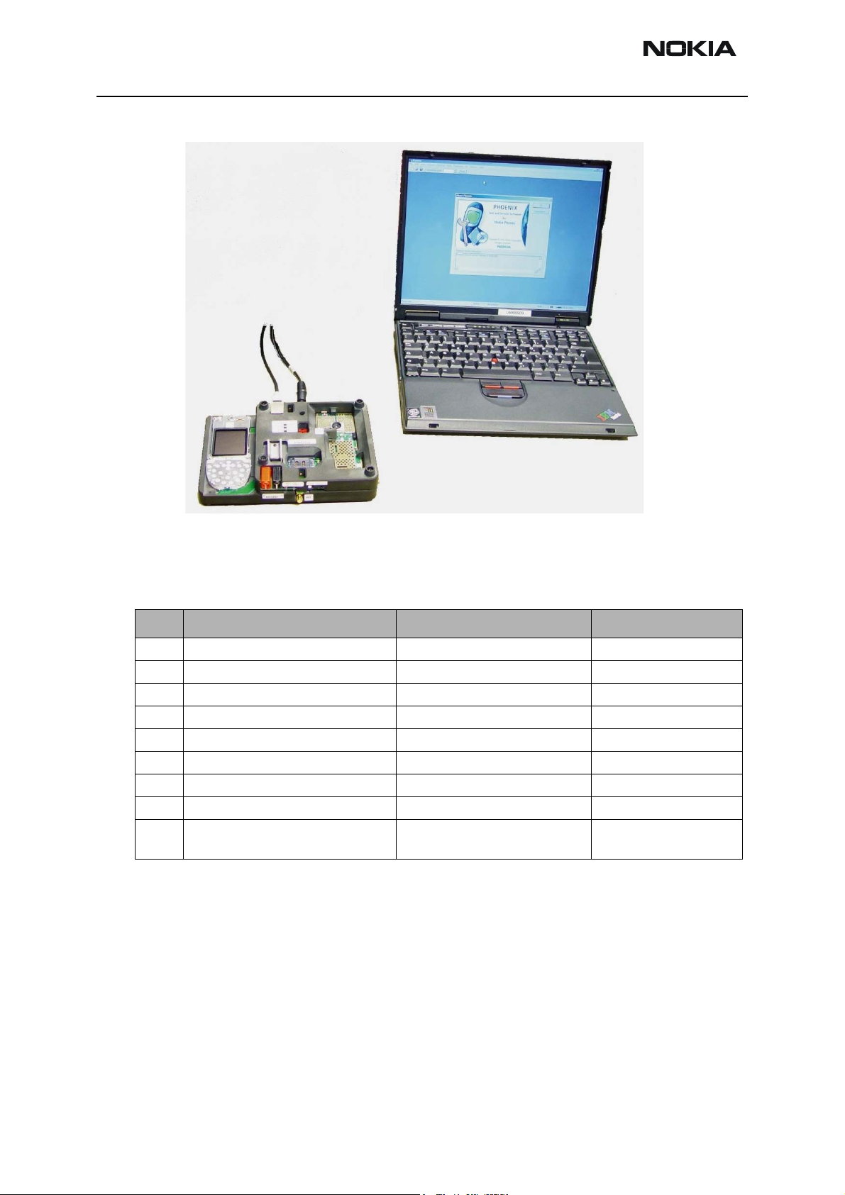
Module Jig Flash concept
The following equipment is required for 3600/3620 (NHM-10) AMS SW update when
system module is placed in the Module Jig MJS-51 and connected through a FPS-8 setup:
Item Description Type Code
1 Module Jig MJS-51 0770579
2 Power cable PCS-1 0730012
3 Modular cable XCS-4 0730178
4 Flash prommer box sales pack FPS-8 0080321
5 Printer cable AXP-8, incl in FPS-8 sales pack
6 D9 – D9 cable AXS-4 , incl in FPS-8 sales pack 0730090
7 Software protection key PKD-1 0750018
8 AC Charger, incl in FPS-8 sales pack 0680032
9 SRAM Module (2 pcs needed
inside FPS-8)
SF12 0080346 (Code includes
Note: All tunings except Zocus calibration can be done with JBV-1/MJF-31 concept by
using XRF12 RF cable.
NHM-10 Phoenix installation instructions
one SRAM module)
Now that cables have been connected, you must install NHM-10 version of Phoenix to
your PC.
NOTE! You must use Phoenix Version A.10 2003.33.5.22 or later in
order to get the correct SW into your Nokia 3600/3620.
Page 3-10 Copyright 2004 Nokia Corporation Issue 2 01/2004
Company Confidential
Page 11

Company Confidential NHM-10
CCS Technical Documentation 3 - Service Software
• Save the package to your hard disk and install it by double clicking it.
NOTE! It is recommended that you uninstall previous Phoenix package before installing
the new one. Do it as follows:
• Click Start -> Settings -> Control Panel
• Add/Remove Prog.
• Phoenix NHM-10 release
• Add/Remove
Reboot your computer after uninstallation
FPS-8 to PC connection Setup instructions
Establish connection between your PC and FPS-8. The procedure is as follows:
• Start phoenix
• Choose File -> Manage connections
• Choose Add
• Select mode, select Manual
• As Media, select FPS-8
• Port number, select the port where you have connected the serial cable of
FPS-8.
•COMBOX_DEF_MEDIA, select FBUS
• Click on Finish
•Press Arrow up key so that FPS8 COM1 FBUS becomes the first on the
list.
• Press Apply and close the window
The connection between PC and FPS-8 has now been configured.
FPS-8 activation
Follow the instructions inside FPS-8 sales pack to get FPS-8 activated.
Checking Application SW version inside FPS-8
When you have connection established to FPS-8 and FPS-8 has been activated, the first
thing to do is to check that you have correct application SW version inside FPS-8. Phoenix SW can check that automatically. The procedure goes as follows:
Go to the partner web site and take newest AMS FPS-8 SW.
Instructions:
• Click Fps-8 downloads
• Click Flash Update
Issue 2 01/2004 Copyright 2004 Nokia Corporation Page 3-11
Company Confidential
Page 12
NHM-10 Company Confidential
3 - Service Software CCS Technical Documentation
• Click AMS/Production version
• Click 2.10.000
• Take file flash_update_02_10_000.exe
• Save it to your hard drive to a place which you can remember
• Go to that directory and click on flash_update_02_10_000.exe
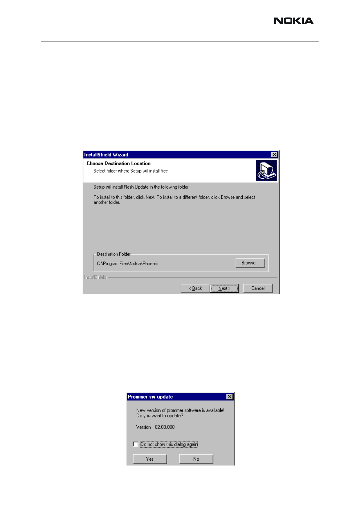
You will see the following note on your screen. Install files to the directory which installation program suggests to you.
Figure 1: InstallShield Wizard screen
When the installation has been finished, FPS-8 files are located in that directory.
You can now start phoenix SW.
When phoenix SW has stared, do the following:
Click on flashing
Click on FPS-8/FPS-8C Maintenance
If SW inside FPS-8 prommer is too old, you get the following notification:
Figure 2: Prommer SW update screen
Page 3-12 Copyright 2004 Nokia Corporation Issue 2 01/2004
Company Confidential
Page 13

Company Confidential NHM-10
CCS Technical Documentation 3 - Service Software
Click Yes and you see on the small scree as the Prommer goes to service mode (mode2 is
lit) SW goes into box, application SW , Secondary boot codes and algorithm codes are
updated.
There is no longer need to do anything special with NHM-10 specific Secondart boot
codes and algorithm codes.
Your PC and FPS-8 is now ready for NHM-10 SW update.
Reprogramming NHM-10
Connecting cables
Once you have the NHM-10 opened and the battery and SIM removed, attach it to the
FLA-48 adapter. Once connected to the FLA-48 the phone goes to local mode and the
screen will not show anything during SW update.
Proceed as follows:
• Connect XCS-4 cable from FLA-48 to FPS-8
• Connect FLC-2 cable from FPS-8 to FLA-48
• There is no need to press the phone power key. Phone has set itself automatically to local mode and it is now ready for SW update.
Settings backup/restore
It is quicker to use MMC user data backup, which can be found at: Menu > extras >
memory > options > backup phone memory.
Start Phoenix SW by double clicking the Phoenix icon on your desktop.
• Now choose File -> Scan product. If phone is ok, you should see the SW
version in lower right-hand corner, e.g. V3.1
• If the scanning finds nothing, the phone is most likely in some strange
mode.
Settings Backup:
• Click Product
•Click User settings
•Click All Settings
•Click Browse
• Choose from Directory C:\Program files\Nokia\Phoenix\Products\ file
Nhl8sett.ini
You will now see the following PC screen:
Issue 2 01/2004 Copyright 2004 Nokia Corporation Page 3-13
Company Confidential
Page 14

NHM-10 Company Confidential
3 - Service Software CCS Technical Documentation
Figure 3: All settings screen
Updating software
New SW package can be updated.
• Choose Flashing -> FPS-8 Flash -> Mark both log flashing and Manual
• Now in Flash file selection window, choose the product code.
Select the correct file:
Now click on OK, and SW update starts.
You will see as the 18 MB package goes into FPS-8 (If transfer is very slow, it is recommended that Parallel port is in ECP mode. Transfer in ECP mode is much faster).
If you do not know how to Change PC Parallel port mode from BIOS, contact your local
support.
Then Phoenix erases flash memories .
And finally you will see how SW package goes into phone (When SW update takes place,
Yellow Mode 1 led is blinking fast)
Selection. Then Click on Flash.
When SW update has ended yellow led stops blinking and you get a note in windows SW.
You will get instructions to turn the phone on. Do so and wait 15 seconds..
Page 3-14 Copyright 2004 Nokia Corporation Issue 2 01/2004
Company Confidential
Page 15

Company Confidential NHM-10
CCS Technical Documentation 3 - Service Software
Formatting user area
User area also neededs to be formatted in order to make sure that there is no user data
left in the phone.
Choose File -> Scan product. In the bottom of the Phoenix window you should see
V3.1, Date, NHM-10(c) NMP
Format User area the following way:
Click Product -> User area format. You will get a note warning you about loss of user
data. Click yes on that.
Phoenix shows Formatting user data area, Please wait screen for a while and gives you a
success note.
Restore settings
Settings can be restored from MMC or Phoenix.
Energy Management Calibration
Connections
NHM-10 phone must be connected to JBV-1 (Docking station) with MJF-31 (Docking
station adapter).
• Connect CA-5S (DC-DC cable) from JBV-1 into to phone charger connector before powering up JBV-1.
• Power up JBV-1 from external power supply: 11-16 V DC. (Do not take
power from FPS-8 in calibration mode).
Phoenix Setup
• Start Phoenix.
• Select FBUS connection.
• Choose M
• Choose Maintenance -> Tuning -> Energy Management Calibration com-
ponent.
Calibration
ain -> Choose product…
1) Mark all channels (ADC, Battery Size…except Battery temperature).
Issue 2 01/2004 Copyright 2004 Nokia Corporation Page 3-15
Company Confidential
Page 16

NHM-10 Company Confidential
3 - Service Software CCS Technical Documentation
Figure 4: Energy Management Calibration screen
2) Press Calibrate button.
After successfull calibration Calibrated indication is shown.
3) Press Save To Phone to save tuning values into phone memory.
After successful saving Values written to phone is indicated.
4) Verify tuning values saving by pressing Read from Phone.
ZOCUS calibration
Zocus calibration is an addition to the existing Energy Management calibration function
done with the JBV-1. This new calibration function is available in Phoenix version A8
2003.17.3.12 and later.
Zocus calibration can be done now in Module Jig MJS-51 or with the Docking Station
Adapter MJF-31 & Docking Station JBV-1.
When Zocus calibration is needed:
Zocus requires re-calibration only, if the Zocus device (N301, LM3819) itself is replaced,
any of the components on the sense input (R383, R384 and C386) or if the flash memory
is corrupted. Zocus does not require re-calibration, if the UEM device is replaced or if any
of the other energy management calibrations are re-calibrated.
Page 3-16 Copyright 2004 Nokia Corporation Issue 2 01/2004
Company Confidential
Page 17

Company Confidential NHM-10
CCS Technical Documentation 3 - Service Software
Procedure
If all Energy Management calibrations are required, tick all boxes with the exception of
Battery Temperature (which is greyed out in the latest version of Phoenix).
If only Zocus calibration is to be done, tick the Battery Current box.
1 Press Calibrate and wait for calibrated values(s) to appear in Calibrated column.
2 Save to Phone.
Empty flash memory calibration procedure:
If tuning values have been lost e.g. due to erasing of the flash memory, the calibration
procedure is slightly different. Due to the way core SW handles tuning values during calibration, it has to be performed twice, first without Zocus (Battery Current) calibration,
and finally with it.
1 Start Energy Management tuning and check that all other boxes except “Battery
Current” (Zocus) are ticked.
2 Press Calibrate and wait for calibrated value(s) to appear in Calibrated column.
3 Save to Phone.
4 Restart Energy Management tuning, this time tick all boxes, also “Battery Cur-
rent”.
5 Press Calibrate and wait for calibrated values(s) to appear in Calibrated column.
6 save to Phone.
Phoenix tuning
Connect the phone to a PC running the Phoenix Service Software.
Start Phoenix Service Software and open FBUS connection
Select File Scan Product
Wait until phone information is shown in the lower right corner of the screen.
Issue 2 01/2004 Copyright 2004 Nokia Corporation Page 3-17
Company Confidential
Page 18

NHM-10 Company Confidential
3 - Service Software CCS Technical Documentation
RF tuning after repairs
Different repairs require different tuning. In general it is necessary to determine in which
section the repair was done to select which tunings to perform. To determine if RF tuning
is necessary after repair it is important that the functionality of the repaired circuit is
understood well. It is recommended to perform complete RF tuning if RF is repaired.
• In general repairs in the TX part will require "TX Power Level Tuning" and "TX IQ
Tuning".
• In general repairs in the RX part or PLL part always require "RX Calibration", “Rx
Band Filter Response Calibration”.
• If Mjoelner is changed all calibrations have to be done.
Other parts interfacing to TX, RX or PLL might require tuning, but common sense should
be used, e.g. if a component that has no influence on RF performance has been changed,
e.g. the microphone, on/off key, mechanical parts or similar, there is no need to do any RF
tuning.
RX Channel Select Filter Calibration
This calibration is calibrating the Base band filter inside Mjoelner. It is done by internally
measuring a prototype filter, for this reason the calibration is done once, not separately
in 2 bands.
Set operating mode to local mode
Select Maintenance Alt-M
Tuning T
RX Channel Select filter Calibration H
A window pops up:
Select Yes and the RX Channel Select Filter Calibration window pops up.
Page 3-18 Copyright 2004 Nokia Corporation Issue 2 01/2004
Company Confidential
Page 19

Company Confidential NHM-10
CCS Technical Documentation 3 - Service Software
The setup should now look like this:
Press Autotune and the optimal values are found.
Press Stop and a new window pops up:
Press Yes and the RX Channel Select Filter Calibration is finished.
RX Calibration (incl. VCXO Calibration)
The "RX calibration" is used to determine gain at different gain-settings for front-end
and Mjoelner and needs to be done in both bands.
RX-calibration requires an external signal generator.
RX-calibration in EGSM850 combines two tunings, VCXO-calibration and AGC-calibration:
Calibration of GSM1900 band only determines AGC values.
The VCXO-calibration finds out a calibration value for VCXO control, an AFC initial
value and 3 AFC-slope coefficients.
Issue 2 01/2004 Copyright 2004 Nokia Corporation Page 3-19
Company Confidential
Page 20

NHM-10 Company Confidential
3 - Service Software CCS Technical Documentation
A value (RF_TEMP), which represents the RF hardware temperature, is determined during
RX Calibration. This temperature value is used by DSP to RSSI reporting in Normal mode
of the phone. It is not visible in the calibration process.
AGC-calibration:
The AGC-calibration finds the gain values of the RX-gain system.
The AGC consists of RF LNA, which can be either on or off (gain difference between on
and off state is nominally 30dB) and BB gain which can be controlled in 6dB steps. This
gives 15 gain steps RSSI0 to RSSI14. LNA is off for steps RSSI0 to RSSI4.
AGC-calibration measures the gain at gain step RSSI4 and RSSI7. The other gain values
are calculated.
VCXO-calibration:
The VCXO-calibration ensures the function of an initial synchronization (before location
update is done) when the mobile station is in Normal mode. For an error free initial synchronization, the 26MHz frequency of the VCXO must be accurate enough. Therefore, a
VCXO cal value is written into the RefOSCCAL register of the Mjoelner.
EGSM
During VCXO-calibration, the VCXO cal value is changed by a DSP-algorithm until a synchronization is possible. This means the VCXO oscillates at 26 MHz with a sufficient minimum frequency error.
To further minimize the frequency error, an initial AFC value is determined by the DSP
and written into RefOSCAFC register of the Mjoelner.
Also the DSP algorithm determines 3 AFC slope coefficients Slope C1...3 during VCXO
calibration. One AFC slope value is not sufficient for Mjoelner F3, because the AFC slope
is non-linear in this chip.
Set operating mode to local mode
Select Maintenance Alt-M
Tuning T
RX Calibration C
Wait until the RX Calibration window pops up.
Select Band GSM 850
Autom.- 60
Page 3-20 Copyright 2004 Nokia Corporation Issue 2 01/2004
Company Confidential
Page 21

Company Confidential NHM-10
CCS Technical Documentation 3 - Service Software
The setup should now look like this:
Select Automatic, press Start and a new window pops up:
Select PM settings, press OK and the window closes.
Now it is possible to press the calibrate button in the RX Calibration window.
Issue 2 01/2004 Copyright 2004 Nokia Corporation Page 3-21
Company Confidential
Page 22

NHM-10 Company Confidential
3 - Service Software CCS Technical Documentation
Press Calibrate and a window pops up:
Connect an external signal generator to the RF connector of the phone and set the generator as told in the window, taking care for external cable losses.
Press OK and the window closes.
A typical result will look like this:
Press Stop in the RX Calibration window and a new window pops up:
Page 3-22 Copyright 2004 Nokia Corporation Issue 2 01/2004
Company Confidential
Page 23

Company Confidential NHM-10
CCS Technical Documentation 3 - Service Software
Press Yes and the EGSM RX Calibration is finished.
GSM1900 (PCS)
Set operating mode to local mode
Select Maintenance Alt-M
Tuning T
RX Calibration C
Wait until the RX Calibration window pops up.
Select Band GSM 1900
Autom. -60
st
Man. -50
1
nd
2
Man. -85
The setup should now look like this:
Select Automatic, press Start and a new window pops up:
Select PM settings, press OK and the window closes.
Now it is possible to press the calibrate button in the RX Calibration window.
Issue 2 01/2004 Copyright 2004 Nokia Corporation Page 3-23
Company Confidential
Page 24

NHM-10 Company Confidential
3 - Service Software CCS Technical Documentation
Press Calibrate and a window pops up:
Connect an external signal generator to the RF connector of the phone and set the generator as told in the window, taking care for external cable losses.
Press OK and the window closes.
A typical result will look like this:
Press Stop in the RX Calibration window and a new window pops up:
Press Yes and the GSM1900 RX Calibration is finished.
Page 3-24 Copyright 2004 Nokia Corporation Issue 2 01/2004
Company Confidential
Page 25

Company Confidential NHM-10
CCS Technical Documentation 3 - Service Software
RX AGC limits
The Rx calibration is only valid if it is within certain limits.
For the most recent limits see NHM-10 Production Testing Requirements,
If calibration is not within limits, there is a fault in the RX chain.
Below the values for RSSI4 and RSSI7 are given:
RSSI4:
band min typ max
EGSM850 81 86 91
GSM1900 79 85 89
RSSI7:
band min typ max
EGSM850 103 108 113
GSM1900 100 104 110
RX Band Filter Response Compensation
EGSM850 (EGSM)
Set operating mode to local mode
Select Maintenance Alt-M
Tuning T
RF Controls F
Wait until the RF Controls window pops up
Select Band GSM 850
Select Maintenance Alt-M
Tuning T
RX Band Filter Response Compensation B
A window pops up:
Select Yes and the RX Band Filter Response Compensation window pops up.
Issue 2 01/2004 Copyright 2004 Nokia Corporation Page 3-25
Company Confidential
Page 26

NHM-10 Company Confidential
3 - Service Software CCS Technical Documentation
The setup should now look like this:
Select Input Signal Level -60dBm
Manual Tuning
Press Manual tuning and a window pops up:
Connect an external signal generator to the RF connector of the phone and set the generator as told in the window.
Press OK and a new window pops up:
Set the generator as told in the window.
Press OK and a new window pops up. Repeat this sequence 9 times until all channels are
done.
Page 3-26 Copyright 2004 Nokia Corporation Issue 2 01/2004
Company Confidential
Page 27

Company Confidential NHM-10
CCS Technical Documentation 3 - Service Software
Press Stop, Write to PM Area (In the RX Band Filter Response Compensation window) and
a window pops up:
Press Yes and the EGSM RX Band Filter Response Compensation is finished.
GSM1900 (PCS)
Set operating mode to local mode
Select Maintenance Alt-M
Tuning T
RF Controls F
Wait until the RF Controls window pops up
Select Band GSM 1900
Select Maintenance Alt-M
Tuning T
RX Band Filter Response Compensation B
A window pops up:
Select Yes and the RX Band Filter Response Compensation window pops up.
Issue 2 01/2004 Copyright 2004 Nokia Corporation Page 3-27
Company Confidential
Page 28

NHM-10 Company Confidential
3 - Service Software CCS Technical Documentation
The setup should now look like this:
Select Input Signal Level -60dBm
Manual Tuning
Press Manual tuning and a window pops up:
Connect an external signal generator to the RF connector of the phone and set the generator as told in the window.
Press OK and a new window pops up:
Set the generator as told in the window.
Press OK and a new window pops up. Repeat this sequense 9 times until all channels are
done.
Page 3-28 Copyright 2004 Nokia Corporation Issue 2 01/2004
Company Confidential
Page 29

Company Confidential NHM-10
CCS Technical Documentation 3 - Service Software
Press Stop, Write to PM Area (In the RX Band Filter Response Compensation window) and
a window pops up:
Press Yes and the EGSM RX Band Filter Response Compensation is finished.
TX I/Q Tuning
This tuning must be done in both bands.
EGSM (EGSM850)
Caution: In case you use a spectrum analyser make sure that the external attenua-
tion (20 - 30dB) between phone and spectrum analyser is high enough
that the input of the analyser can’t be destroyed. Adjust the reference
level offset according to the insertion loss from the phone to the spectrum
analyser .
PC/Phone operation:
Set operating mode to local mode
Select Maintenance Alt-M
Tuning T
TX IQ Tuning I
Wait until the TX IQ Tuning window pops up.
Select Maintenance Alt-M
Tuning T
RF Controls F
Wait until the RF Controls window pops up.
Connect a Spectrum Analyzer or GSM tester with the option *Narrow Spectrum' to the
RF connector of the phone.
If a spectrum analyzer is used then use the following settings.
EGSM/EGSM850
Center Frequency 897.4 MHz
Frequency Span 300 kHz
Resolution Bandwidth 3kHz
Video Bandwidth 3kHz
Sweep Time 3 sec.
Issue 2 01/2004 Copyright 2004 Nokia Corporation Page 3-29
Company Confidential
Page 30

NHM-10 Company Confidential
3 - Service Software CCS Technical Documentation
EGSM/EGSM850
Sweep Type Clear/Write
Detector Type Max Peak
Reference level 35 dBm
Marker 1 897.33229 MHz
Marker 2 897.4 MHz
Marker 3 897.46771 MHz
Select in the RF Controls Window:
Select Band GSM 850
Active Unit TX
Operation Mode Burst
RX/TX Channel 37
TX PA Mode Free
TX Data Type All1
Select in the TX IQ Tuning Window:
Select “Load from Product”
“Save to Product”
Press Start
Select again in the RF Controls Window:
Select TX Power Level 5
The setup should now look like this:
Page 3-30 Copyright 2004 Nokia Corporation Issue 2 01/2004
Company Confidential
Page 31

Company Confidential NHM-10
m
5
5
CCS Technical Documentation 3 - Service Software
The Spectrum Analyzer now shows a plot like this:
Ref Lvl
Ref Lvl
35 dBm
35 dBm
3
27.5 dB Offset
30
20
10
0
-10
-20
-30
-40
-50
Marker 1 [T1]
33.35 dBm
897.33229000 MHz
1
RBW 3 kHz
VBW 3 kHz
SWT 3 s
2
RF Att 30 dB
Unit dB
1 [T1] 33.35 dBm
897.33229000 MHz
2 [T1] -6.76 dBm
897.40000000 MHz
3 [T1] -10.74 dBm
897.46771000 MHz
3
A
1MA
-60
-6
Date: 14.JAN.2002 13:11:55
The purpose of this tuning is to tune the carrier signal and the +67kHz signal to a minimum level (Marker 2 and 3).
Use the variables 'TX I DC offset' and 'TX Q DC offset' to adjust the carrier signal to a
minimum level (Marker 2).
After tuning to the minimum the level difference between the peak levels at marker 1
and 2 must exceed 40dB.
Tuning is possible by using arrow keys on the keyboard. Pushing the sliders by using the
mouse is less sensitive but even possible.
30 kHz/Center 897.4 MHz Span 300 kHz
Issue 2 01/2004 Copyright 2004 Nokia Corporation Page 3-31
Company Confidential
Page 32

NHM-10 Company Confidential
m
5
5
3 - Service Software CCS Technical Documentation
The Spectrum Analyzer now shows a plot like this:
Ref Lvl
Ref Lvl
35 dBm
35 dBm
3
27.5 dB Offset
30
20
10
0
-10
-20
-30
-40
Marker 1 [T1]
33.65 dBm
897.33229000 MHz
1
RBW 3 kHz
VBW 3 kHz
SWT 3 s
2
RF Att 30 dB
Unit dB
1 [T1] 33.65 dBm
897.33229000 MHz
2 [T1] -19.54 dBm
897.40000000 MHz
3 [T1] -10.79 dBm
897.46771000 MHz
3
A
1MA
-50
-60
-6
Date: 14.JAN.2002 13:20:36
Use the variables 'Amplitude difference' and 'Phase difference' to adjust the +67kHz signal to a minimum level (Marker 3). After tuning to the minimum the level difference
between the peak levels at marker 1 and 3 must exceed 40dB. Tuning is possible by using
arrow keys on the keyboard. Pushing the sliders by using the mouse is less sensitive but
even possible.
30 kHz/Center 897.4 MHz Span 300 kHz
Page 3-32 Copyright 2004 Nokia Corporation Issue 2 01/2004
Company Confidential
Page 33

Company Confidential NHM-10
A
5
5
CCS Technical Documentation 3 - Service Software
The Spectrum Analyzer now shows a plot like this:
3
30
20
10
0
-10
-20
-30
-40
Ref Lvl
Ref Lvl
35 dBm
35 dBm
27.5 dB Offset
Marker 1 [T1]
33.40 dBm
897.33229000 MHz
1
RBW 3 kHz
VBW 3 kHz
SWT 3 s
2
RF Att 30 dB
Unit dBm
1 [T1] 33.40 dBm
897.33229000 MHz
2 [T1] -20.35 dBm
897.40000000 MHz
3 [T1] -27.60 dBm
897.46771000 MHz
3
A
1M
-50
-60
-6
Date: 14.JAN.2002 13:23:02
Select again in the RF Controls Window:
Select “Save to Product”
Press Stop and the values are stored in the phone.
The EGSM TX IQ Tuning is now finished.
Note: The optimal values for "TX I and Q Offset" and "Amplitude and Phase Difference"
vary from phone to phone.
30 kHz/Center 897.4 MHz Span 300 kHz
Issue 2 01/2004 Copyright 2004 Nokia Corporation Page 3-33
Company Confidential
Page 34

NHM-10 Company Confidential
3 - Service Software CCS Technical Documentation
GSM1900 (PCS)
Caution: In case you use a spectrum analyser make sure that the external attenua-
tion (20 - 30dB) between phone and spectrum analyser is high enough
that the input of the analyser can’t be destroyed. Adjust the reference
level offset according to the insertion loss from the phone to the spectrum
analyser .
PC/Phone operation:
Set operating mode to local mode
Select Maintenance Alt-M
Tuning T
TX IQ Tuning I
Wait until the TX IQ Tuning window pops up.
Select Maintenance Alt-M
Tuning T
RF Controls F
Wait until the RF Controls window pops up.
Connect a Spectrum Analyzer or GSM tester with the option *Narrow Spectrum' to the
RF connector of the phone.
If a spectrum analyzer is used then use the following settings.
GSM1900
Center Frequency 1880MHz
Frequency Span 300 kHz
Resolution Bandwidth 3 kHz
Video Bandwidth 3 kHz
Sweep Time 3 sek.
Sweep Type Clear/Write
Detector Type Max Peak
Reference level 35 dBm
Marker 1 1879.93229 MHz
Marker 2 1880 MHz
Marker 3 1880.06771 MHz
Select in the RF Controls Window:
Select Band GSM 1900
Page 3-34 Copyright 2004 Nokia Corporation Issue 2 01/2004
Company Confidential
Page 35

Company Confidential NHM-10
CCS Technical Documentation 3 - Service Software
Active UnitTX
Operation Mode Burst
RX/TX Channel 661
TX PA Mode Free
TX Data Type All1
Select in the TX IQ Tuning Window:
Select “Load from Product”
“Save to Product”
Press Start
Select again in the RF Controls Window:
Select TX Power Level 0
The setup should now look like this:
Issue 2 01/2004 Copyright 2004 Nokia Corporation Page 3-35
Company Confidential
Page 36

NHM-10 Company Confidential
A
5
5
3 - Service Software CCS Technical Documentation
The Spectrum Analyzer now shows a plot like this:
3
30
20
10
0
-10
-20
-30
-40
Ref Lvl
Ref Lvl
35 dBm
35 dBm
27.5 dB Offset
Marker 3 [T1]
-12.20 dBm
1.88006771 GHz
1
RBW 3 kHz
VBW 3 kHz
SWT 3 s
2
RF Att 30 dB
Unit dBm
3 [T1] -12.20 dBm
1.88006771 GHz
1 [T1] 27.81 dBm
1.87993229 GHz
2 [T1] 4.13 dBm
1.88000000 GHz
3
A
1M
-50
-60
-6
Date: 15.JAN.2002 10:53:47
The purpose of this tuning is to tune the carrier signal and the +67kHz signal to a minimum level (Marker 2 and 3).
Use the variables 'TX I DC offset' and 'TX Q DC offset' to adjust the carrier signal to a
minimum level (Marker 2).
After tuning to the minimum the level difference between the peak levels at marker 1
and 2 must exceed 40dB.
Tuning is possible by using arrow keys on the keyboard. Pushing the sliders by using the
mouse is less sensitive but even possible.
30 kHz/Center 1.88 GHz Span 300 kHz
Page 3-36 Copyright 2004 Nokia Corporation Issue 2 01/2004
Company Confidential
Page 37

Company Confidential NHM-10
A
5
5
CCS Technical Documentation 3 - Service Software
The Spectrum Analyzer now shows a plot like this:
3
30
20
10
0
-10
-20
-30
-40
Ref Lvl
Ref Lvl
35 dBm
35 dBm
27.5 dB Offset
Marker 3 [T1]
-15.03 dBm
1.88006771 GHz
1
RBW 3 kHz
VBW 3 kHz
SWT 3 s
2
RF Att 30 dB
Unit dBm
3 [T1] -15.03 dBm
1.88006771 GHz
1 [T1] 25.16 dBm
1.87993229 GHz
2 [T1] -23.51 dBm
1.88000000 GHz
3
A
1M
-50
-60
-6
Date: 15.JAN.2002 10:57:06
Use the variables ‘Amplitude difference’ and Phase difference’ to adjust the +67KHz signal to a minimum level (Marker 3). After tuning to the minimum the level difference
between the peak levels at marker 1 and 3 must exceed 40dB, Tuning is possible by using
arrow keys on the keyboard. Pushing the sliders by using the mouse is less sensitive but
even possible’
30 kHz/Center 1.88 GHz Span 300 kHz
Issue 2 01/2004 Copyright 2004 Nokia Corporation Page 3-37
Company Confidential
Page 38

NHM-10 Company Confidential
A
5
5
3 - Service Software CCS Technical Documentation
The Spectrum Analyzer now shows a plot like this:
3
30
20
10
0
-10
-20
-30
-40
Ref Lvl
Ref Lvl
35 dBm
35 dBm
27.5 dB Offset
Marker 3 [T1]
-27.22 dBm
1.88006771 GHz
1
RBW 3 kHz
VBW 3 kHz
SWT 3 s
2
RF Att 30 dB
Unit dBm
3 [T1] -27.22 dBm
1.88006771 GHz
1 [T1] 25.76 dBm
1.87993229 GHz
2 [T1] -27.30 dBm
1.88000000 GHz
3
A
1M
-50
-60
-6
30 kHz/Center 1.88 GHz Span 300 kHz
Date: 15.JAN.2002 10:58:09
Select ‘Save to Product’
Press Stop in the TX IQ Tuning Window and the values are stored in the phone.
The GSM1900 TX IQ Tuning is now finished.
Note: The optimal values for “TX I and Q Offset” and “Amplitude and Phase Difference” vary
from phone to phone.
TX Power tuning
This tuning must be done in both bands.
Note: TX Power tuning must be done with a peak power meter, e.g. Anritsu model ML2408A
with Anritsu Peak Power Sensor MA2442A and a suitable attenuator.
Page 3-38 Copyright 2004 Nokia Corporation Issue 2 01/2004
Company Confidential
Page 39

Company Confidential NHM-10
CCS Technical Documentation 3 - Service Software
The use of power meter in GSM testers is likely to cause larger error than the use of a
dedicated power meter and might cause the phone to be non-compliant with GSM specifications.
EGSM (EGSM850)
Set operating mode to local mode
Select Maintenance Tuning TX Power Level Tuning
Wait until the TX Power Level Tuning window pops up.
Connect a calibrated powermeter to the RF connector of the phone.
Select Band GSM 850
Active Unit TX
Press Start and a window pops up:
Select Permanent memory, press OK and the window closes.
Select TX Data Type Random
The setup should now look like this:
Issue 2 01/2004 Copyright 2004 Nokia Corporation Page 3-39
Company Confidential
Page 40

NHM-10 Company Confidential
3 - Service Software CCS Technical Documentation
Select TX PA Mode High
Tune Base level to –27 dBm.
Adjust DAC Values for Power Level 5 (32 dBm), 15 (13 dBm) and 19 (5 dBm) according to
Target values. The Power levels may differ from Phoenix mentioned target power levels.
Press calculate, check if all levels match the target values, correct if necessary.
Select TX PA Mode Low
Adjust DAC Values for Power Level 7, 15 and 19 according to Target values.
Press calculate, check if all levels match the target values, correct if necessary.
Press Stop and a window pops up:
Select 'Save values to Phone Permanent Memory'
Press Yes and the EGSM TX Power Level Tuning is finished.
GSM1900 (PCS)
Set operating mode to local mode
Select Maintenance Tuning TX Power Level Tuning
Wait until the TX Power Level Tuning window pops up.
Connect a calibrated powermeter to the RF connector of the phone.
Select Band GSM 1900
Press Start and a window pops up:
Active Unit TX
Page 3-40 Copyright 2004 Nokia Corporation Issue 2 01/2004
Company Confidential
Page 41

Company Confidential NHM-10
CCS Technical Documentation 3 - Service Software
Select Permanent memory, press OK and the window closes.
Select TX Data Type Random
The setup should now look like this:
Select TX PA Mode High
Tune Base level to –27 dBm.
Adjust DAC Values for Power Level 0 (30 dBm), 11 (8.2 dBm) and 15 (1 dBm). The Power
levels may differ from in Phoenix mentioned target power levels.
Press calculate, check if all levels match the target values, correct if necessary.
Press Stop and a window pops up:
Select 'Save values to Phone Permanent Memory'
Press Yes and the GSM1900 TX Power Level Tuning is finished.
Issue 2 01/2004 Copyright 2004 Nokia Corporation Page 3-41
Company Confidential
Page 42

NHM-10 Company Confidential
3 - Service Software CCS Technical Documentation
Appendix 3-A NHM-10 - 3620
Essentially the 3620 is the same as the 3600 apart from the User Interface layout being
in a standard 4 x 3 matrix.
Phoenix software Version A.10 2003.33.5.22 or later is the same for both the 3600 and
the 3620.
The phone software runs a routine if it is a 3600/3620 device so that the 3620 software
(64K colour) will not run on the 3600.
If a 3600 is flashed with the 3620 software, boot up will fail, this can be corrected by
flashing with the correct software.
Page 3-42 Copyright 2004 Nokia Corporation Issue 2 01/2004
Company Confidential
 Loading...