

Page 1

CC Technical Documentation
NPM-10 (3595) Series Transceivers
Troubleshooting - BB
Issue 2 03/2004 Confidential ©2004 Nokia Corporation
Page 2
NPM-10 (3595)
Troubleshooting - BB CC Technical Documentation
Contents Page
Baseband Testpoints ...................................................................................................... 3
Fault-Finding Charts ....................................................................................................3
Phone is Dead ..............................................................................................................4
Flash Programming Does Not Work ...........................................................................6
Power Does Not Stay on or Phone is Jammed ............................................................7
Display Information: "Contact Service" ......................................................................8
Phone Does Not Register Onto the Network, or the Phone Cannot Make a Call ........9
SIM-related Faults .....................................................................................................10
Insert SIM Card Fault.............................................................................................. 10
SIM-Card Rejected.................................................................................................. 11
Audio-related Faults ..................................................................................................12
Charging Failure ........................................................................................................15
Page 2 ©2004 Nokia Corporation Confidential Issue 2 03/2004
Page 3
NPM-10 (3595)
CC Technical Documentation Troubleshooting - BB
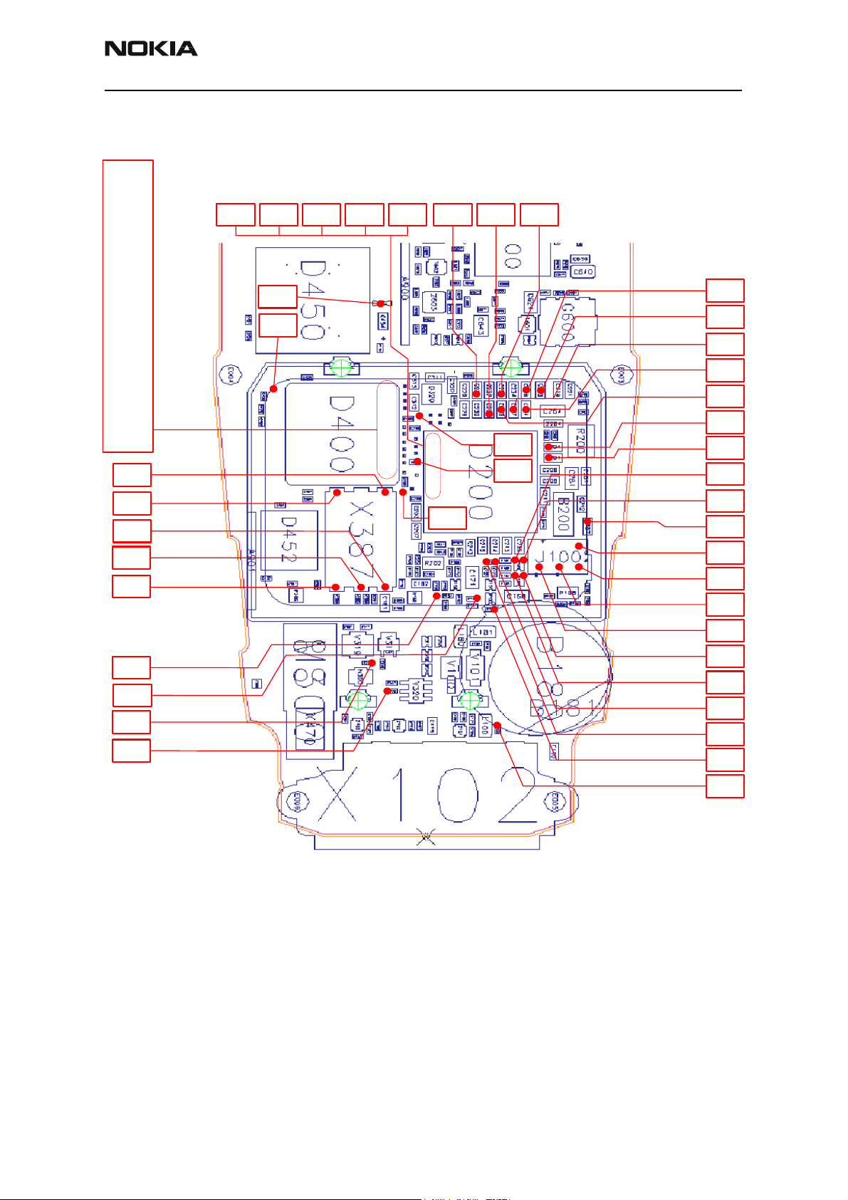
Baseband Testpoints
J420
FLSCSX
J425
RFCLK
J417
EXTRDX
J418
RLS2CSX
J414
DBUSDA
J402
PURX
J404
SLEEPCLK
J408
CBUSEN
J406
CBUSCLK
J407
CBUSDA
J412
FBUSRX
GND
SIM
I/O
VSIM
SIM
RST
SIM
CLK
J150
HOOKINT
R166
MICB2
R310
KLIGHT
R306
DLIGHT
J413
DBUSCL
J405
UEMINT
J413
DBUSCL
J413
DBUSCL
J415
DBUSEN
J411
FBUSTX
J420
J425
J417
J418
J414
J402
J404
J408
J406
J407
J412
J409
MBUXTX
J413
J405
J415
J411
J409
C231
VREFRF0
J410
MBUSR
C222
VR4
J403
SLEEPX
C218
VIO
C225
VR6
C226
VR5
C223
VR2
C227
VR3
C224
VR7
C208
VCORE
C206
VANA
C205
VFLASH
HFCM
HF
C157
HEADINT
VPP
FBUS-
TX
MBUS
FBUS-
RX
R161
EARP
R161
EARN
R164
MIC1N
R164
MIC1P
R165
MICB1
C100
VCHARIN
Figure 1: Baseband testpoints
Fault-Finding Charts
In this section, fault-finding charts are provided for the most common NPM-10 (3595)
errors.
Note: Since both D200 (UEM) and D400(UPP) are underfilled, they cannot be replaced. If either D200
or D400 is defective, the entire PWB has to be discarded.
Issue 2 03/2004 ©2004 Nokia Corporation Confidential Page 3
Page 4

NPM-10 (3595)
Troubleshooting - BB CC Technical Documentation
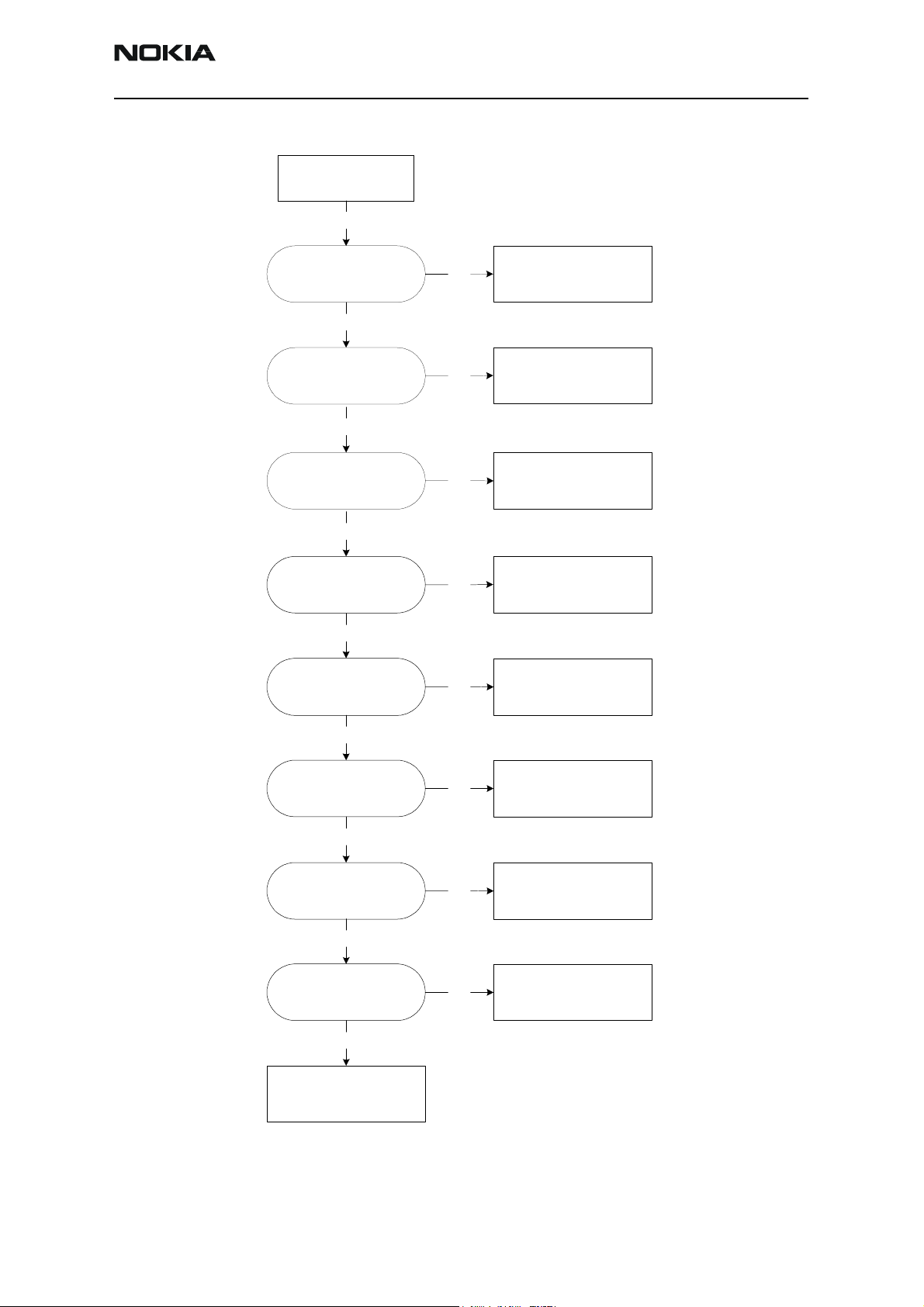
Phone is Dead
This means that the phone does not draw any current at all when a supply is connected
and/or the power key is pressed. It is assumed that the voltage supplied is 3.6 VDC. The
UEM prevents any functionality whatsoever at battery/supply levels below 2.9 VDC.
Page 4 ©2004 Nokia Corporation Confidential Issue 2 03/2004
Page 5
NPM-10 (3595)
CC Technical Documentation Troubleshooting - BB
Phone is dead
Yes
X101
VBAT - 3.6 VDC
Yes
Z261, C261, Z264, C264
Voltage = 3.6 VDC
Yes
S300
Pin 1 & 3 is HIGH when power
key is untouched
Yes
S300
Pin 1 & 3 is 0VDC(LOW) when
power key is pressed
Yes
J404
Sleep clock is
32.768 kHz, 1.8 Vpp
No
No
No
No
No
CHECK:
X101
CHECK:
Z261, C261, Z264, C264
CHECK:
R217, C310
CHECK:
S300, PWB
CHECK:
B200, C209, C210, PWB.
Else defective D200*
Yes
J402
PURX = 1.8VDC 1 sec. after
power key is pressed
Yes
C227
VR3 = 2.78 VDC
Yes
J425
26 MHz clock min.
300 mVACpp,
probe Cin=10 - 13 pF/10M
Yes
CHECK:
D450 (Flash).
Else defective D200*
Figure 2: Phone is dead
No
No
No
CHECK:
PWB.
Else defective D200*
CHECK:
C227, PWB.
Else defective D200*
CHECK:
C227, PWB.
Else defective D200*
Issue 2 03/2004 ©2004 Nokia Corporation Confidential Page 5
Page 6

NPM-10 (3595)
Troubleshooting - BB CC Technical Documentation
Flash Programming Does Not Work
The flash programming can only be done via the pads on the PWB (J100).
In case of flash failure in FLALI station, the problem is most likely related to SMD
problems. Possible failures could be short-circuit of balls under µBGAs (UEM, UPP,
FLASH), or missing or misaligned components.
In flash programming error cases, the flash prommer can give some information about a
fault. The fault information message could be “Phone doesn't set FBUS_TX line low”.
Because of the use of uBGA components, it is not possible to verify if there is a short
circuit in control- and address lines of MCU (UPP) and memory (flash).
Flash programming
does not work
Error from prommer:
“Phone doesn’t set FBUS_TX
line low .”
Yes
J100, R108
Check connection between
pad 1, 2 and 3 on J 100 and
R108
Yes
J409, J410, J411, J412
Voltage level a t 1.8 VDC
Yes
Try reading MCU ID
with Phoenix:
Reading OK?
Yes
Try reading flash ID
with Phoenix:
Reading OK?
No
No
No
No
CHECK:
R108, PWB
CHECK:
PWB, else defective D2 00
CHECK:
PWB, else defective D4 00
CHECK:
Replace D450
Yes
Reflash the phone
Figure 3: Flash programming does not work
Page 6 ©2004 Nokia Corporation Confidential Issue 2 03/2004
Page 7

NPM-10 (3595)
CC Technical Documentation Troubleshooting - BB
Power Does Not Stay on or Phone is Jammed
If this kind of failure is presenting itself immediately after FLALI, it is most likely caused
by ASICs missing contact with the PWB.
If for some reason the MCU does not service the watchdog register within the UEM, the
operations watchdog runs out after approximately 32 seconds. Unfortunately, the service
routine cannot be measured.
Power doesn’t stay
on or phone is
jammed
J404
Sleep clock = 32.768 kHz,
1.8 Vpp
Yes
J402
PURX = 1.8 VDC, 1 second
after power key is pressed
Yes
Do UI functionality and
keys react to pressure?
Yes
J425
26 MHz clock min.
300 mVACpp, probe
Cin=10 - 13 pF/10M
No
No
No
No
CHECK:
B200, C209, C210, PWB. Else
defective D200
CHECK:
PWB, else defective D200
CHECK:
D450, key mat, light guide, PWB.
Else defective D400
CHECK:
C425, C426, R425, R426, N600
(Mjoelner)
Yes
Reflash the phone
Figure 4: Power does not stay on or the phone is jammed
Issue 2 03/2004 ©2004 Nokia Corporation Confidential Page 7
Page 8

NPM-10 (3595)
Troubleshooting - BB CC Technical Documentation
Display Information: "Contact Service"
This error can only happen at power up where several self-tests run. If any of these test
cases fail, the display shows the "Contact Service" message.
These are individual test cases, so the following list of possible errors has no
chronological order. Use common sense and experience to decide where to begin error
hunting.
Display shows
“Contact Service”
Yes
EarDa and MicDa
between UPP and UEM?
MBUS interface between
UPP and UEM?
AuxDa and UEMInt
between UPP and UEM?
SleepX and SleepClk
between UPP and UEM?
TXI/QD and RXI/QD?
SIM interface between
UPP and UEM?
Key is stuck
Flash checksum
y ASIC version vs. compilation flag, PMM checksum
y PMM validity
y Warranty Information State
y SIM-Lock
A-cover, key mat, light guide,
No
R205
Check R205
(no short/open-circuit )
CHECK:
PWB.
Reflash phone
CHECK:
PWB. Else defective D200* or
Else defective D450 (FLASH)
D400*
Error Still Present
CHECK:
PWB.
Figure 5: Display shows “Contact Service”
Page 8 ©2004 Nokia Corporation Confidential Issue 2 03/2004
Page 9

NPM-10 (3595)
CC Technical Documentation Troubleshooting - BB
Phone Does Not Register Onto the Network, or the Phone Cannot Make a Call
If the phone does not register to the network, the fault can be in either BB or RF. Only a
few signals can be tested because several signals are buried in one or more of the inner
layers of the PWB. First, check that the SIM LOCK is not causing the error by using a
Test-SIM card and connecting the phone to a tester.
Phone does not register to
network or phone cannot
make a call
C222, C223, C224, C225, C226, C227
Voltage = ~2.78 VDC all during GSM frame (call
mode). Use TXP on C64 6 as trigger.
Yes
C230, C231
Voltage = ~1.35 VDC all during
GSM-frame (call mode).
Use TXP on C646 as trigger.
Yes
J608, J609, J610
Check RF serial bus during GSM frame:
Logic HIGH = 1.8 VDC
Logic LOW = 0 VDC
RFBUSCLK (J608), RFB US D A (J609),
RFBUSEN1X (J610)
Yes
R601, R603
Check analog signals during GSM-frame (RX slot):
RXIP/N (R601) = 0-1.45 VDC
RXQP/N (R603) = 0- 1.45 VDC
No
No
No
No
C222, C223, C224, C225, C226,
CHECK:
C227, PWB. Else defective D200
or D400*
CHECK:
C230, C231, PWB. Else defective
D200* or D400*
CHECK:
PWB. Else defective D200* or
D400*
CHECK:
PWB. Else defective D200* or
D400*
Yes
Check analog signals during GSM-frame (TX slot):
R610, R611
TXIP/N (R610) = 1-1.75 VDC
TXQP/N (R611) = 1-1.7 5 VD C
Yes
CHECK RF
No
R610, R611, PWB. Else defective
CHECK:
D200* or D400*
Figure 6: Phone does not register to network or phone cannot make a call
Issue 2 03/2004 ©2004 Nokia Corporation Confidential Page 9
Page 10

NPM-10 (3595)
Troubleshooting - BB CC Technical Documentation
SIM-related Faults
Insert SIM Card Fault
The hardware of the SIM interface from UEM (D200) to the SIM connector (X387) can be
tested without a SIM card. When the phone power is switched on, first check for a 1.8 V
SIM card and then a 3 V SIM card. The phone will try this four times, whereafter it will
display ”Insert SIM card”.
Display shows
“Insert SIM Card”
Yes
X387
Verify that the phone checks for
1.8 V-SIM, and then 3 V-SIM
during power-up.
(See Figure 8)
Yes
SIM interface OK
Figure 7: Display shows “Insert SIM Card”
Ch1 : VSIM
Ch2 : RESET
No
Ch3 : CLOCK
Ch4 : DATA
CHECK:
X387, R386, PWB.
Else defective D200*
Figure 8: Checking for SIM voltage during power-up
Page 10 ©2004 Nokia Corporation Confidential Issue 2 03/2004
Page 11

NPM-10 (3595)
CC Technical Documentation Troubleshooting - BB
SIM-Card Rejected
The error ”SIM Card Rejected” means that the ATR message received from the SIM card is
corrupted, e.g. the data signal levels are wrong. The first data is always ATR and it is sent
from the card to the phone.
Display shows
“SIM Card Rejected”
Yes
X387
VSIM = min. 1.6 V (1.8 V Card)
VSIM = min. 2.8 V (3 V Card)
(See Figure 10)
Yes
X387
ATR data can be seen at SIM
data pin.
Yes
SIM Interface OK
Figure 9: Display shows “SIM Card Rejected”
No
No
Figure 10 shows a normal SIM power-up.
Ch1 : VSIM
Ch2 : RESET
CHECK:
R386, PWB.
Else defective D200*
CHECK:
X387, R386, PWB.
Ch3 : CLOCK
Ch4 : DATA
Figure 10: Normal SIM power-up sequence
Issue 2 03/2004 ©2004 Nokia Corporation Confidential Page 11
Page 12

NPM-10 (3595)
Troubleshooting - BB CC Technical Documentation
Audio-related Faults
Earpiece does not
work
Replace:
Earpiece
Error Still Present
Z150, R161
Check Z150 and R161 are
working correctly
(no short/open circuit)
Yes
Defective D200*
Figure 11: Earpiece does not work
No
CHECK:
R386, PWB.
Else Defective D200*
Page 12 ©2004 Nokia Corporation Confidential Issue 2 03/2004
Page 13

NPM-10 (3595)
CC Technical Documentation Troubleshooting - BB
Microphone does not
work and there is no
mechanical problem
C103, Z100
Check C103 and Z100 are
working correctly
(no short/open circuit)
Yes
Replace:
System Connector
Error Still Pre sent
R165
Check voltage level on R165
towards UEM (bias) =2.1 V
Yes
R153
Check voltage level on R153
towards mic lines (bias) =
1.0 V - 1.4 V
No
No
No
Replace:
C103 and/or Z100
CHECK:
R165, C168, PWB.
Else Defective D200*
CHECK:
R153, R157, C151, C152, C153,
C154, PWB.
Figure 12: Microphone does not work and there is no mechanical problem
Headset earpiece does
not work and there is no
mechanical problem
R183, Z102
Check R183 and Z102 are
working correctly
(no open circuit)
No
Replace:
R103 and/or Z102
Yes
Defective D200*
Figure 13: Headset earpiece does not work and there is no mechanical problem
Issue 2 03/2004 ©2004 Nokia Corporation Confidential Page 13
Page 14

NPM-10 (3595)
Troubleshooting - BB CC Technical Documentation
Headset microphone
does not work and there
is no mechanical
problem
Check voltage level on R166
R166
towards UEM (bias) = 2.1 V
Yes
R151
Check voltage level on R151
towards UEM (bias) =
1.0 V - 1.4 V
Yes
R152, R165, R168, C155,
C156, C172, C170, C173,
C174, Z101
Check XMIC line to UEM (D200)
Error still present
Defective D200*
No
No
No
Replace:
C183 and/or Z102
Check:
R166, R151, and C171
Replace:
Defective component
Figure 14: Headset microphone does not work and there is no mechanical problem
Page 14 ©2004 Nokia Corporation Confidential Issue 2 03/2004
Page 15

NPM-10 (3595)
CC Technical Documentation Troubleshooting - BB
Charging Failure
The phone is OFF, the battery is
completely empty (<=3.1 VDC), and
there is no current from the charger
when connected.
L100
VCHAR>2.1 VDC
No
F100, L100, V101, C100, R200,
Check:
system connector
Yes
Defective D200*
Figure 15: Phone is OFF, the battery is empty, and there is no current from the charger
The phone is ON or OFF, the battery
has nominal voltage (<=3.6 VDC),
and there is no current from the
charger when connected.
L100
VCHAR>3.6 VDC
No
F100, L100, V101, C100, R200,
Check:
system connector
Yes
Defective D200* or D400*
Figure 16: Phone is ON or OFF, the battery has a nominal charge, and there is no current from the charger
Issue 2 03/2004 ©2004 Nokia Corporation Confidential Page 15
Page 16

NPM-10 (3595)
Troubleshooting - BB CC Technical Documentation
Display shows “Not
Charging” when
charger is connected
R206
Voltage on R206 towards D200
is ~0.8 VDC when power is
connected
(BSI must be 75K)
Yes
No
CHECK:
X101, R202, R206, C240
R207
Voltage (use sc op e) on R207
towards D200 is ~0.9 VDC at
peak (BTEMP must be 47K)
Yes
R200
Voltage on R200 towards D200
same as VBAT voltage
Yes
R200
Voltage rises slowly on R200
towards D200 when charger is
connected
Yes
Check:
PWB
No
No
No
CHECK:
X101, R202, R207, C220
CHECK:
R200, PWB.
Else defective D200*
CHECK:
PWB.
Else defective D200*
Figure 17: Display shows “Not Charging” when charger is connected
Page 16 ©2004 Nokia Corporation Confidential Issue 2 03/2004
 Loading...