

Page 1

CC Technical Documentation
NPM-10 (3595) Series Transceivers
Disassembly/Assembly
Issue 2 03/2004 Confidential ©2004 Nokia Corporation
Page 2
NPM-10 (3595)
Disassembly/Assembly CC Technical Documentation
Disassemble the NPM-10 (3595) Transceiver
Preparation for Disassembly
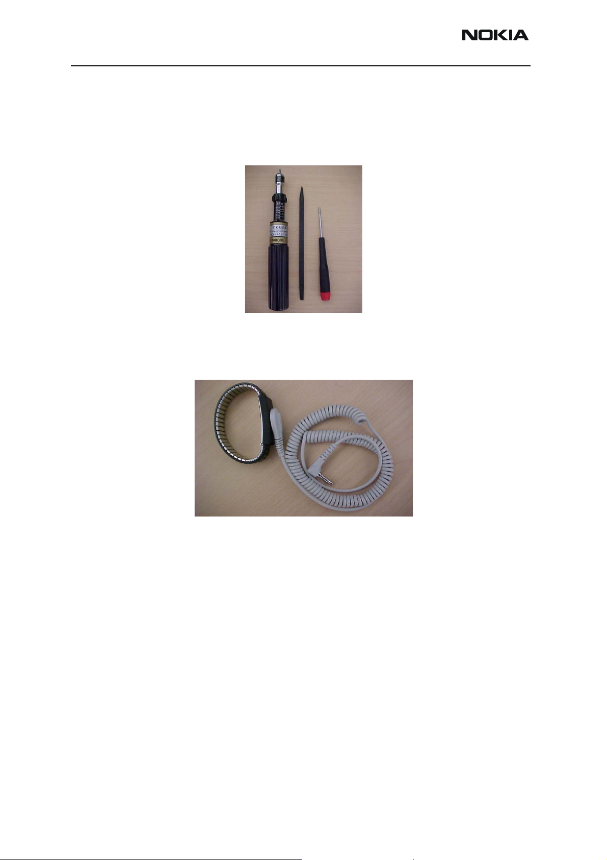
Disassembly Tools
Figure 1:
Left to right: Torque-limiting screwdriver (torque set at 28N-cm),
fiberglass soldering aid, and T6 Torx+ driver
ESD Protection
Some form of ESD protection should be used when handling the PWB and other electronic components. Figure 2 shows a wrist strap, “which” can be grounded to a bench.
This or some other form of ESD protection should be used when handling the phone.
Assembly Instructions
To assemble the phone, follow the steps in the "Disassembly Instructions" section in
reverse order.
Figure 2: ESD protective wrist strap
Page 2 ©2004 Nokia Corporation Confidential Issue 2 03/2004
Page 3
NPM-10 (3595)
CC Technical Documentation Disassembly/Assembly
Disassembly Instructions
Following are the instructions for disassembling the phone.
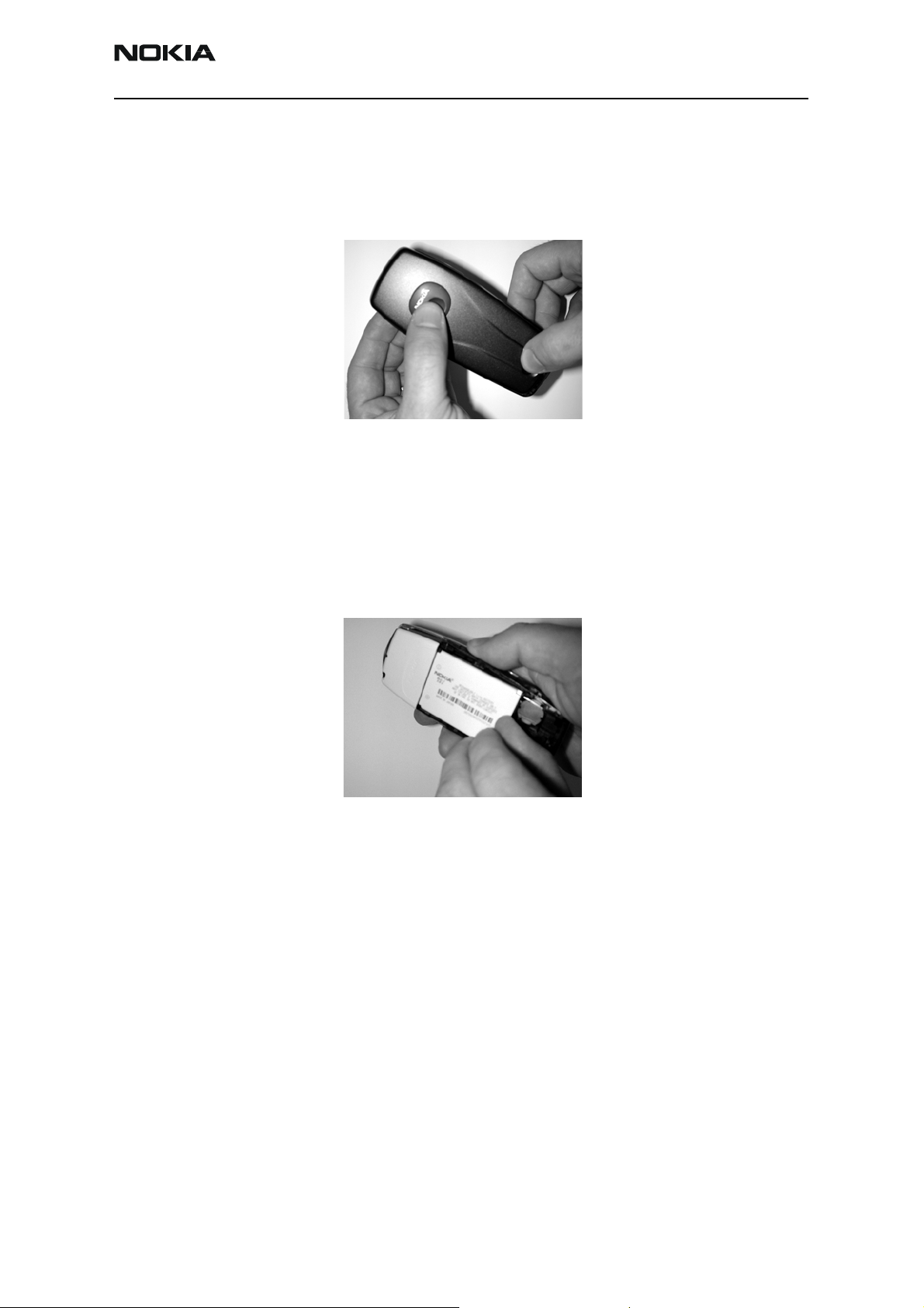
1. Remove the B-cover
Figure 3: Removing the B-cover
1. Press and hold the release button.
2. With the other hand, place your thumb on the logo badge and push B-cover
towards the top of the phone.
3. Once the B-cover is pushed forward, lift it off to remove.
2. Remove the Battery
• Remove the battery out by lifting from the bottom of the battery compartment.
Figure 4: Removing the battery
Issue 2 03/2004 ©2004 Nokia Corporation Confidential Page 3
Page 4

NPM-10 (3595)
Disassembly/Assembly CC Technical Documentation
3. Remove the SIM Card
Figure 5: Removing the SIM card
1. Press plastic spring down.
2. Place the thumb from the other hand on the SIM card.
3. Press and slide the SIM card towards the top of the phone.
4. Remove the A-cover
1. Place the thumb under the edge of the A-cover with the fingers on top.
2. Pull the A-cover gently until a snap deactivates.
5. Remove the Screws (Torx #6)
Figure 6: Removing the A-cover
Figure 7: Removing the screws
Page 4 ©2004 Nokia Corporation Confidential Issue 2 03/2004
Page 5

NPM-10 (3595)
CC Technical Documentation Disassembly/Assembly
6. Remove the Lightguide Assembly
Use screwdriver size 2.50 – 3.50 mm
1
2
PWB
Bottom
connector
3
Between PWB & Bottom connector. Be careful not to
damage the Bottom connector.
Figure 8: Removing the lightguide assembly
Issue 2 03/2004 ©2004 Nokia Corporation Confidential Page 5
Page 6

NPM-10 (3595)
Disassembly/Assembly CC Technical Documentation
7. Remove the Metal Frame and Earpiece
1b
1a
2
3
Figure 9: Removing the metal frame and earpiece
Note: Use screwdriver size 2.50 – 3.50 mm.
1. Turn the screwdriver at the snaps, only on one side.
2. When removing the metal frame, be careful not to damage the four springs in
the corners.
3. Remove the earpiece.
Page 6 ©2004 Nokia Corporation Confidential Issue 2 03/2004
Page 7

NPM-10 (3595)
CC Technical Documentation Disassembly/Assembly
8. Remove the PWB Assembly
LED
Figure 10: Removing the PWB assembly
1. Remove PWB assembly.
2. Place the PWB on an ESD table with the LED upwards.
Issue 2 03/2004 ©2004 Nokia Corporation Confidential Page 7
Page 8

NPM-10 (3595)
Disassembly/Assembly CC Technical Documentation
9. Remove the Shielding Lids
Figure 11: Removing the shielding lids
• Remove the shielding lids as shown in Figure 11. Do not re-use the shielding lids
once they are removed.
When working with the PWB, always use a repair jig.
Figure 12: Repair jig
Page 8 ©2004 Nokia Corporation Confidential Issue 2 03/2004
Page 9

NPM-10 (3595)
CC Technical Documentation Disassembly/Assembly
10. Remove Components from D-cover Assembly
The following components are removable:
Note: Use screwdriver size 2.50 – 3.50 mm.
1. Power key
2. Battery connector
3. Vibrate assembly
4. Bottom connector
5. MALT speaker
Remove MALT speaker by turning the screwdriver as shown in step 5.
Issue 2 03/2004 ©2004 Nokia Corporation Confidential Page 9
Page 10

NPM-10 (3595)
Disassembly/Assembly CC Technical Documentation
This page intentionally left blank.
Page 10 ©2004 Nokia Corporation Confidential Issue 2 03/2004
 Loading...