

Page 1

Customer Care Solutions
Technical Documentation
SERVICE
MANUAL
[NMP Part No. 0275717]
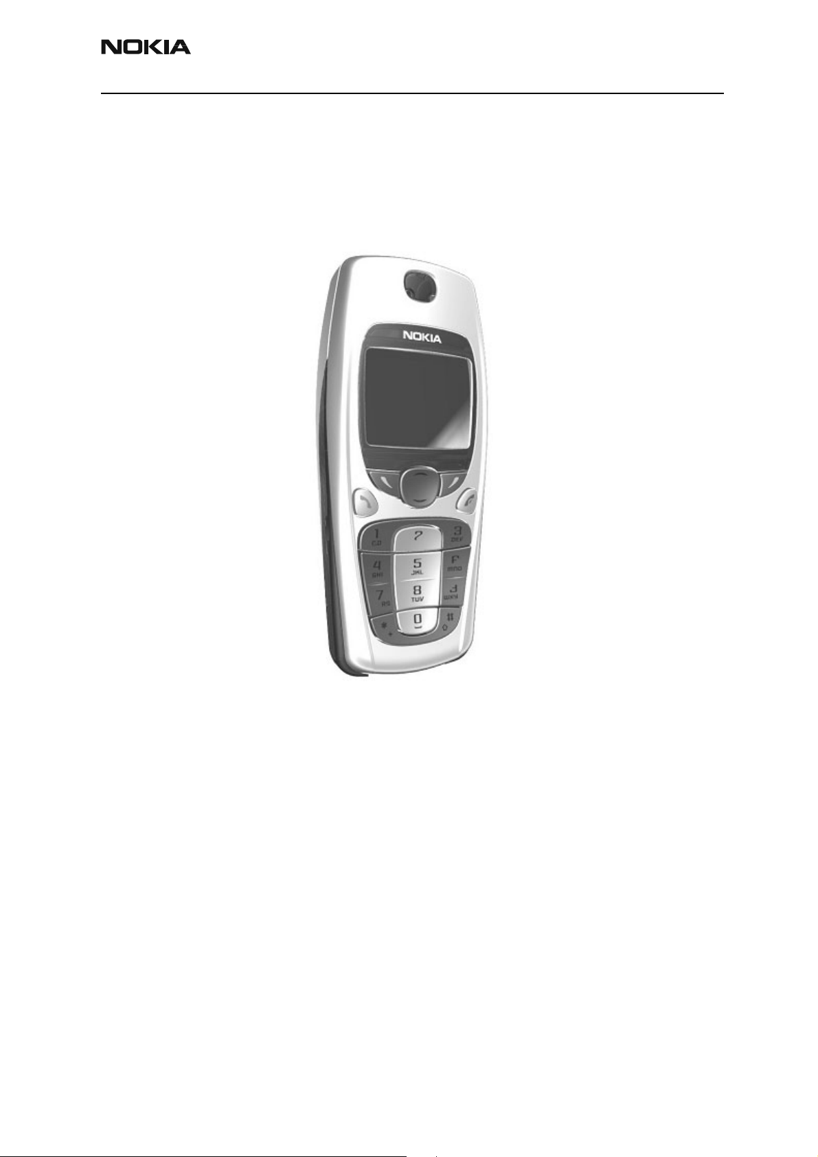
Nokia 3560 (RH-14)
Cellular Phones
Issue 1 Copyright 2003 Nokia Corporation. Confidential. All Rights Reserved
Page 2

Customer Care Solutions
Technical Documentation
Amendment Record Sheet
Amendment No Date Inserted By Comments
05/2003 J Fraser Issue 1
Issue 1 Copyright 2003 Nokia Corporation. Confidential. All Rights Reserved
Page 3

Customer Care Solutions
Technical Documentation
Nokia 3560 (RH-14) Cellular Phones
Service Manual – Overall Manual Contents
Service Manual comprising
Nokia 3560 (RH-14) Transceiver booklet comprising
Foreword
General
Parts
Service Software Instructions
Service Tools
Disassembly/Assembly
Troubleshooting
System Module
Schematics
Issue 1 Copyright 2003 Nokia Corporation. Confidential. All Rights Reserved
Page 4

This document is intended for use by qualified service personnel only.
Company Policy
Our policy is of continuous development; details of all technical modifications will be
included with service bulletins.
While every endeavour has been made to ensure the accuracy of this document, some
errors may exist. If any errors are found by the reader, Nokia Corporation should be notified in writing.
Please state:
Customer Care Solutions
Technical Documentation
IMPORTANT
Title of the Document + Issue Number/Date of publication
Latest Amendment Number (if applicable)
Page(s) and/or Figure(s) in error
Please send to: Nokia Corporation
CCS Technical Documentation
PO Box 86
FIN-24101 SALO
Finland
Issue 1 Copyright 2003 Nokia Corporation. Confidential. All Rights Reserved
Page 5

Customer Care Solutions
Technical Documentation
Warnings and Cautions
Please refer to the phone's user guide for instructions relating to operation, care and
maintenance including important safety information. Note also the following:
Warnings:
1. CARE MUST BE TAKEN ON INSTALLATION IN VEHICLES FITTED WITH
ELECTRONIC ENGINE MANAGEMENT SYSTEMS AND ANTI-SKID BRAKING
SYSTEMS. UNDER CERTAIN FAULT CONDITIONS, EMITTED RF ENERGY CAN
AFFECT THEIR OPERATION. IF NECESSARY, CONSULT THE VEHICLE DEALER/
MANUFACTURER TO DETERMINE THE IMMUNITY OF VEHICLE ELECTRONIC
SYSTEMS TO RF ENERGY.
2. THE HANDPORTABLE TELEPHONE MUST NOT BE OPERATED IN AREAS LIKELY
TO CONTAIN POTENTIALLY EXPLOSIVE ATMOSPHERES EG PETROL STATIONS
(SERVICE STATIONS), BLASTING AREAS ETC.
3. OPERATION OF ANY RADIO TRANSMITTING EQUIPMENT, INCLUDING
Cautions:
1. Servicing and alignment must be undertaken by qualified personnel only.
2. Ensure all work is carried out at an anti-static workstation and that an
3. Ensure solder, wire, or foreign matter does not enter the telephone as
4. Use only approved components as specified in the parts list.
5. Ensure all components, modules screws and insulators are correctly
CELLULAR TELEPHONES, MAY INTERFERE WITH THE FUNCTIONALITY OF
INADEQUATELY PROTECTED MEDICAL DEVICES. CONSULT A PHYSICIAN OR
THE MANUFACTURER OF THE MEDICAL DEVICE IF YOU HAVE ANY
QUESTIONS. OTHER ELECTRONIC EQUIPMENT MAY ALSO BE SUBJECT TO
INTERFERENCE.
anti-static wrist strap is worn.
damage may result.
re-fitted after servicing and alignment. Ensure all cables and wires are
repositioned correctly.
Issue 1 Copyright 2003 Nokia Corporation. Confidential. All Rights Reserved
Page 6

Customer Care Solutions
Technical Documentation
Issue 1 Copyright 2003 Nokia Corporation. Confidential. All Rights Reserved
Page 7

CCS Technical Documentation
RH-14 Series Transceivers
General Information
Issue 1 05/2003 Confidential Nokia Corporation
Page 8

RH-14
General Information CCS Technical Documentation
Page 2 Nokia Corporation Confidential Issue 1 05/2003
Page 9

RH-14
CCS Technical Documentation General Information
Contents
Page No
Product Selection ........................................................................................................... 5
Accessories ..................................................................................................................6
Module List ..................................................................................................................7
Technical Specifications ..............................................................................................7
General Specifications of Transceiver RH-14 .......................................................... 7
Issue 1 05/2003 Confidential Nokia Corporation Page 3
Page 10

RH-14
General Information CCS Technical Documentation
Page 4 Nokia Corporation Confidential Issue 1 05/2003
Page 11
RH-14
CCS Technical Documentation General Information
Product Selection
RH-14 (Model 3560) phone is a dual-band, dual-mode radio transceiver unit for 800/
1900 MHz Time Division Multiple Access (TDMA) networks. The transceiver consists of
system/RF module, keypad module, LCD module, and assembly parts. The user interface
(UI) consists of normal number, talk, end, scroll key, and two selection keys in the keymat.
The antenna is internal; antenna connection is provided by spring from PWB to antenna.
Issue 1 05/2003 Confidential Nokia Corporation Page 5
Page 12
RH-14
General Information CCS Technical Documentation
Accessories
Name Type Material Code
Standard Li-ion Battery 1000 mAh BLC-2 0670436
AC Travel Charger (Euro plug) 207-253 Vac ACP-7E 0675144
AC Travel Charger (US plug) 108-132 Vac ACP-7U 0675143
AC Travel Charger (US plug) 198-242 Vac ACP-7C 0675158
AC Travel Charger (UK plug) 207-253 Vac ACP-7X 0675145
AC Travel Charger (UK plug) 180-220 Vac ACP-7H 0675146
AC Travel Charger (Australia plug) 216-264 Vac ACP-7A 0675148
Performance Travel Charger Euro plug 90-264 Vac ACP-8E 0675195
Performance Travel Charger Korea plug 90-264 Vac ACP-8K 0675199
Performance Travel Charger UK plug 90-264 Vac ACP-8X 0675197
Performance Travel Charger US plug 90-264 Vac ACP-8U 0675196
Performance Travel Charger China plug 90-264 Vac ACP-8C 0675211
Performance Travel Charger Australia plug 90-264 Vac ACP-8A 0675214
Travel Charger: ACP-12E 0675294
Travel Charger ACP-12U 0675302
Extra Battery Charger DDC-1 0675243
Mounting Plate MKU-1 0620036
Swivel Mount HHS-9 0620037
Cigarette Lighter Charger LCH-9 0675120
Handsfree Microphone HFM-8 0690016
Headset HDE-2 0694075
Headset HDC-5 0271467
Headset HDC-10 0273651
Headset HDB-5 0694107
Phone Adapter (TTY/Headset) HDA-9 0694116
Loopset LPS-3 0272419
Passive Car Holder MCC-7 0650052
Cigarette Lighter Charger LCH-12 0675328
Express Car Kit CARK-125 0085193
Complete Car Kit CARK-134 0080641
Page 6 Nokia Corporation Confidential Issue 1 05/2003
Page 13
RH-14
CCS Technical Documentation General Information
Module List
TDMA800/1900 + AMPS TDMA800
Type designator RH-14 RH-21
Model number 3560 3520
Technical Specifications
General Specifications of Transceivers RH-14
Table 1: Specifications for TDMA800+AMPS
Parameter Unit
Cellular system TDMA800 + AMPS
RX frequency band 869.01 - 893.97 MHz
TX frequency band 824.01 - 848.97 MHz
Output power AMPS: -5 to +24.7 dBm
TDMA800: -5 to +28 dBm
Number of RF channels 832
Channel spacing 30 kHz
Table 2: Specifications for TDMA 1900
Parameter Unit
Cellular system TDMA1900 + AMPS
RX frequency band 1930.05 - 1989.99 MHz
TX frequency band 1850.01 - 1909.95 MHz
Output power -5 to +28 dBm / 0.3 mW - 630 mW
Number of RF channels 1999
Channel spacing 30 kHz
Issue 1 05/2003 Confidential Nokia Corporation Page 7
Page 14

RH-14
General Information CCS Technical Documentation
Page 8 Nokia Corporation Confidential Issue 1 05/2003
Page 15

CCS Technical Documentation
RH-14 Series Transceivers
Parts Lists
Issue 1 05/2003 Confidential Nokia Corporation
Page 16

RH-14
Parts Lists CCS Technical Documentation
Page 2 Nokia Corporation Confidential Issue 1 05/2003
Page 17

RH-14
CCS Technical Documentation Parts Lists
Contents
Page No
Component Layout......................................................................................................... 5
3560 Component Layout - Top ....................................................................................5
Exploded Views............................................................................................................. 7
Main Assembly ............................................................................................................7
Assembly Parts List .....................................................................................................7
Internal Module Assembly Structure ...........................................................................8
Assembly Parts List .....................................................................................................8
Parts List ........................................................................................................................ 9
RH-14 (3560) — EDMS Issue 2.11 Code: 0202068 ...................................................9
Issue 1 05/2003 Nokia Corporation Confidential Page 3
Page 18

RH-14
Parts Lists CCS Technical Documentation
Page 4 Nokia Corporation Confidential Issue 1 05/2003
Page 19
RH-14
CCS Technical Documentation Parts Lists
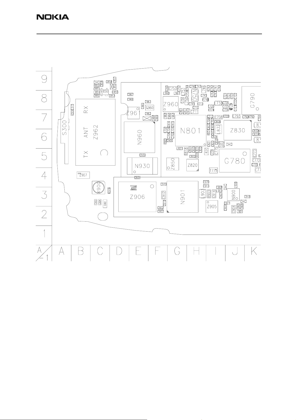
Component Layout
3560 Component Layout - Top
Issue 1 05/2003 Nokia Corporation Confidential Page 5
Page 20
RH-14
Parts Lists CCS Technical Documentation
Page 6 Nokia Corporation Confidential Issue 1 05/2003
Page 21
RH-14
CCS Technical Documentation Parts Lists
Exploded Views
Main Assembly
Assembly Parts List
Item No. Qty. Part Code Value
1 1 (INTERNAL) MODULE DUAL BAND 0510315 DMC06652
2 1 (Internal) Module Single Band 0510318 DMC06652
3 1 Keymat Assembly - Latin 9790837 DMC06537
4 1 Keymat Assembly - Hebrew 9790846 DMC05982
5 1 A-cover Assembly - Pearl White 9491237 DMC06073
6 1 B-cover Assembly - Pearl White 9491242 DMC06032
Issue 1 05/2003 Nokia Corporation Confidential Page 7
Page 22
RH-14
Parts Lists CCS Technical Documentation
Internal Module Assembly Structure
Assembly Parts List
Item No. Qty. Part Code Value
1 1 D-COVER ASSEMBLY - DUAL BAND 9491055 DMC05767
2 1 D-cover Assembly - single band 9491109 DMC05767
3 1 Color Display/UI Assembly 4850277 DMC05329
4 1 PWB - DUAL BAND 0202068
5 1 PWB - single band 0202092
6 6 Screws 1.8 x 7 mm 6290107 DMD05791
Page 8 Nokia Corporation Confidential Issue 1 05/2003
Page 23
RH-14
CCS Technical Documentation Parts Lists
Parts List
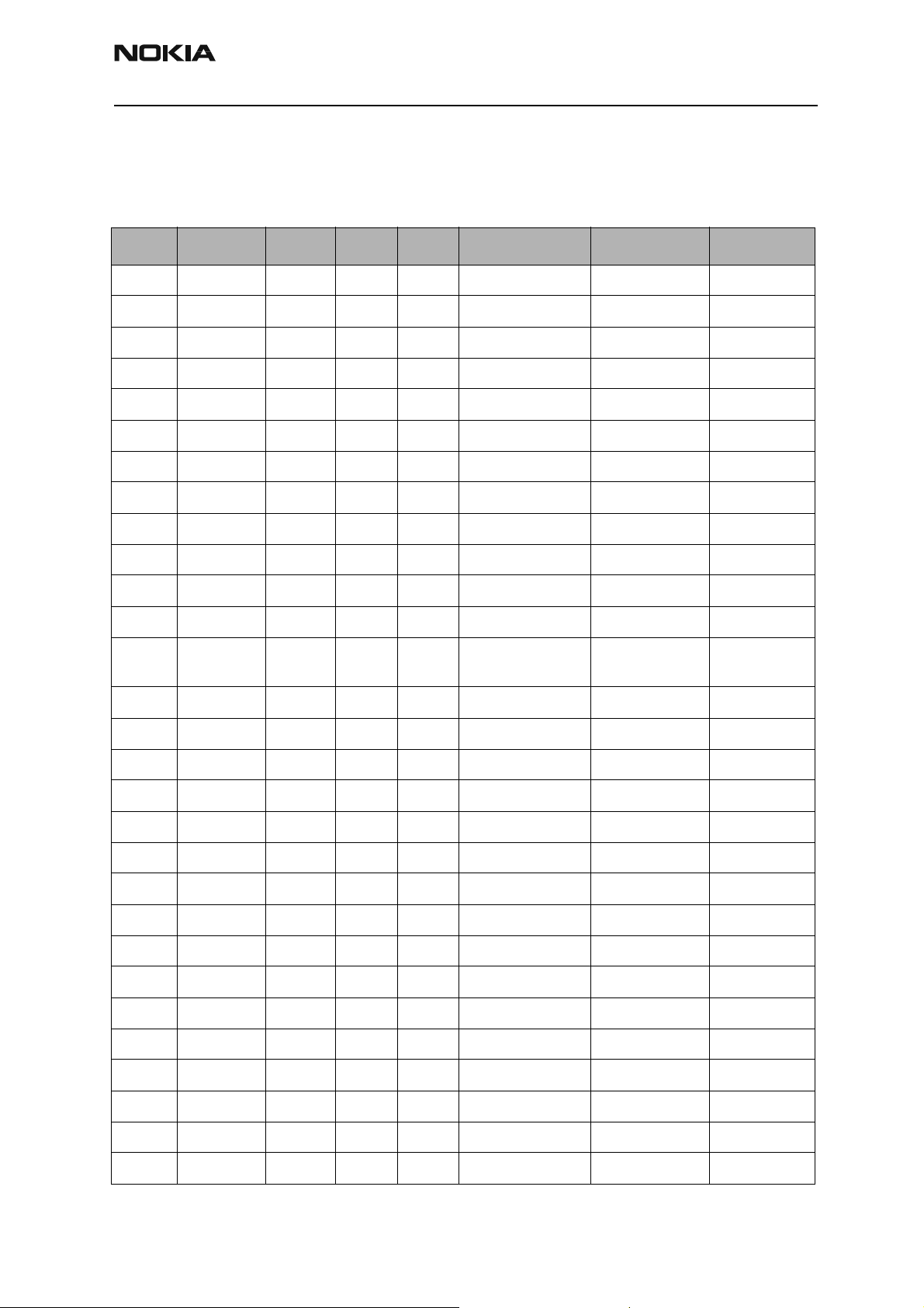
RH-14 (3560) — EDMS Issue 2.11 Code: 0202068
Item Code Side X Y Description Value Type
R100 1430788 Top P 5 chip res 0W06 22K J 0402
R101 1620063 Top N 5 res network 0W06 4X100R J 0804
R102 1430812 Top O 6 chip res 0W06 220K J 0402
R150 1430754 Top Q 6 chip res 0W06 1K0 J 0402
R151 1430754 Top Q 6 chip res 0W06 1K0 J 0402
R152 1620031 Top R 7 res network 0W06 2X1K0 J 0404
R153 1430754 Top Q 7 chip res 0W06 1K0 J 0402
R154 1430778 Top U 5 chip res 0W06 10K J 0402
R156 1430762 Top Q 8 chip res 0W06 2K2 J 0402
R157 1620035 Top M 8 res network 0W06 2X10R J 0404
R159 1430788 Top Q 7 chip res 0W06 22K J 0402
R162 1430762 Top R 7 chip res 0W06 2K2 J 0402
R163 1825033 Top T 5 chip varistor VWM14V
VC46V
R164 1430796 Top Q 7 chip res 0W06 47K J 0402
R165 1430710 Top Q 9 chip res 0W06 22R J 0402
R166 1430762 Top R 7 chip res 0W06 2K2 J 0402
R175 1430710 Top Q 9 chip res 0W06 22R J 0402
R181 1430770 Top O 5 chip res 0W06 4K7 J 0402
R182 1430788 Top P 5 chip res 0W06 22K J 0402
R183 1430770 Top O 5 chip res 0W06 4K7 J 0402
R184 1430778 Top Q 5 chip res 0W06 10K J 0402
R200 1419003 Top R 9 chip res 0W5 0R22 J 200 PPM 1210
0402
R202 1430087 Top Q 6 chip res 0W06 100K J 0603
R203 1430087 Top Q 6 chip res 0W06 100K J 0603
R204 1430804 Top P 6 chip res 0W06 100K J 0402
R205 1430770 Top P 6 chip res 0W06 4K7 J 0402
R206 1430804 Top Q 7 chip res 0W06 100K J 0402
R207 1430770 Top P 6 chip res 0W06 4K7 J 0402
R208 1430778 Top Q 8 chip res 0W06 10K J 0402
Issue 1 05/2003 Nokia Corporation Confidential Page 9
Page 24

RH-14
Parts Lists CCS Technical Documentation
Item Code Side X Y Description Value Type
R209 1430804 Top Q 8 chip res 0W06 100K J 0402
R215 1430087 Top Q 6 chip res 0W06 100K J 0603
R221 1430268 Top M 6 chip res 0W06 27K F 100 PPM 0603
R237 1430690 Top M 6 chip res jumper 0R0 0402
R301 1430770 Top B 7 chip res 0W06 4K7 J 0402
R310 1430754 Top N 5 chip res 0W06 1K0 J 0402
R311 1430700 Top O 5 chip res 0W06 10R J 0402
R316 1430778 Top C 3 chip res 0W06 10K J 0402
R320 1430117 Top M 6 chip res 0W06 100R F 200 PPM 0402
R450 1430803 Top N 5 chip res 0W06 47K7 F 200 PPM 0402
R709 1430700 Top J 7 chip res 0W06 10R J 0402
R712 1430700 Top H 8 chip res 0W06 10R J 0402
R721 1430774 Top J 8 chip res 0W06 6K8 J 0402
R722 1430772 Top J 8 chip res 0W06 5K6 J 0402
R723 1430764 Top J 8 chip res 0W06 3K3 J 0402
R724 1430691 Top I 7 chip res 0W06 2R2 J 0402
R741 1430770 Top I 8 chip res 0W06 4K7 J 0402
R742 1430772 Top I 8 chip res 0W06 5K6 J 0402
R743 1430764 Top I 9 chip res 0W06 3K3 J 0402
R744 1430744 Top H 9 chip res 0W06 470R J 0402
R745 1430700 Top F 9 chip res 0W06 10R J 0402
R771 1430786 Top K 5 chip res 0W06 18K J 0402
R772 1430726 Top K 5 chip res 0W06 100R J 0402
R773 1430700 Top K 5 chip res 0W06 10R J 0402
R774 1430700 Top I 6 chip res 0W06 10R J 0402
R791 1430778 Top K 7 chip res 0W06 10K J 0402
R792 1430700 Top K 7 chip res 0W06 10R J 0402
R818 1430268 Top G 5 chip res 0W06 27K F 100 PPM 0603
R830 1430832 Top K 6 chip res 0W06 2K7 J 0402
R831 1430734 Top I 6 chip res 0W06 220R J 0402
R850 1430788 Top C 9 chip res 0W06 22K J 0402
R900 1430718 Top F 6 chip res 0W06 47R J 0402
Page 10 Nokia Corporation Confidential Issue 1 05/2003
Page 25

RH-14
CCS Technical Documentation Parts Lists
Item Code Side X Y Description Value Type
R903 1430169 Top I 3 chip res 0W06 56R J 0603
C100 2320536 Top S 6 chip cap NP0 10P J 50V 0402
C102 2320536 Top S 6 chip cap NP0 10P J 50V 0402
C105 2320744 Top U 7 chip cap X7R 1N0 K 50V 0402
C150 2320544 Top T 6 chip cap NP0 22P J 50V 0402
C151 2320783 Top Q 7 chip cap X7R 33N K 10V 0402
C152 2320783 Top Q 7 chip cap X7R 33N K 10V 0402
C153 2320546 Top R 7 chip cap NP0 27P J 50V 0402
C155 2320805 Top Q 7 chip cap X5R 100N K 10V 0402
C156 2320805 Top Q 7 chip cap X5R 100N K 10V 0402
C157 2320560 Top Q 8 chip cap X7R 680P J 50V 0402
C158 2320544 Top T 5 chip cap NP0 22P J 50V 0402
C159 2320560 Top Q 7 chip cap X7R 680P J 50V 0402
C160 2320481 Top T 5 chip cap X5R 1U K 6V3 0603
C161 2320744 Top Q 6 chip cap X7R 1N0 K 50V 0402
C162 2320744 Top U 4 chip cap X7R 1N0 K 50V 0402
C163 2320744 Top R 7 chip cap X7R 1N0 K 50V 0402
C164 2320744 Top T 5 chip cap X7R 1N0 K 50V 0402
C165 2320546 Top R 7 chip cap NP0 27P J 50V 0402
C166 2312201 Top Q 9 chip cap
C168 2320544 Top U 4 chip cap NP0 22P J 50V 0402
C169 2320805 Top Q 8 chip cap X5R 100N K 10V 0402
C170 2320546 Top R 7 chip cap NP0 27P J 50V 0402
C172 2320546 Top M 9 chip cap NP0 27P J 50V 0402
C173 2320546 Top L 9 chip cap NP0 27P J 50V 0402
C174 2320544 Top T 4 chip cap NP0 22P J 50V 0402
C175 2320744 Top T 5 chip cap X7R 1N0 K 50V 0402
C176 2320544 Top T 5 chip cap NP0 22P J 50V 0402
C177 2320544 Top T 5 chip cap NP0 22P J 50V 0402
C179 2320805 Top Q 5 chip cap X5R 100N K 10V 0402
C180 2320805 Top O 5 chip cap X5R 100N K 10V 0402
C181 2320481 Top P 5 chip cap X5R 1U K 6V3 0603
Issue 1 05/2003 Nokia Corporation Confidential Page 11
Page 26

RH-14
Parts Lists CCS Technical Documentation
Item Code Side X Y Description Value Type
C182 2320481 Top P 5 chip cap X5R 1U K 6V3 0603
C183 2320582 Top P 5 chip cap X7R 820P J 50V 0402
C184 2320805 Top O 5 chip cap X5R 100N K 10V 0402
C201 2320481 Top N 9 chip cap X5R 1U K 6V3 0603
C202 2320778 Top R 8 chip cap X7R 10N K 16V 0402
C204 2320481 Top O 9 chip cap X5R 1U K 6V3 0603
C205 2320481 Top O 9 chip cap X5R 1U K 6V3 0603
C206 2320481 Top P 9 chip cap X5R 1U K 6V3 0603
C207 2320481 Top Q 6 chip cap X5R 1U K 6V3 0603
C208 2320481 Top M 9 chip cap X5R 1U K 6V3 0603
C209 2320536 Top P 9 chip cap NP0 10P J 50V 0402
C210 2320536 Top P 8 chip cap NP0 10P J 50V 0402
C211 2320481 Top P 9 chip cap X5R 1U K 6V3 0603
C212 2320481 Top P 9 chip cap X5R 1U K 6V3 0603
C213 2320481 Top O 9 chip cap X5R 1U K 6V3 0603
C215 2320481 Top Q 7 chip cap X5R 1U K 6V3 0603
C216 2320481 Top Q 7 chip cap X5R 1U K 6V3 0603
C217 2320778 Top P 6 chip cap X7R 10N K 16V 0402
C218 2320805 Top O 6 chip cap X5R 100N K 10V 0402
C219 2320481 Top N 9 chip cap X5R 1U K 6V3 0603
C220 2320744 Top P 6 chip cap X7R 1N0 K 50V 0402
C221 2320481 Top M 9 chip cap X5R 1U K 6V3 0603
C222 2320481 Top M 8 chip cap X5R 1U K 6V3 0603
C223 2320481 Top M 8 chip cap X5R 1U K 6V3 0603
C224 2320481 Top M 8 chip cap X5R 1U K 6V3 0603
C225 2320481 Top M 8 chip cap X5R 1U K 6V3 0603
C226 2320481 Top M 7 chip cap X5R 1U K 6V3 0603
C227 2320544 Top Q 8 chip cap NP0 22P J 50V 0402
C228 2320481 Top M 6 chip cap X5R 1U K 6V3 0603
C229 2320481 Top M 7 chip cap X5R 1U K 6V3 0603
C230 2320778 Top P 6 chip cap X7R 10N K 16V 0402
C231 2320481 Top M 7 chip cap X5R 1U K 6V3 0603
Page 12 Nokia Corporation Confidential Issue 1 05/2003
Page 27

RH-14
CCS Technical Documentation Parts Lists
Item Code Side X Y Description Value Type
C232 2320481 Top M 7 chip cap X5R 1U K 6V3 0603
C233 2320481 Top M 9 chip cap X5R 1U K 6V3 0603
C234 2320481 Top M 7 chip cap X5R 1U K 6V3 0603
C235 2320805 Top Q 8 chip cap X5R 100N K 10V 0402
C236 2320805 Top N 6 chip cap X5R 100N K 10V 0402
C237 2320805 Top M 6 chip cap X5R 100N K 10V 0402
C238 2320491 Top N 9 chip cap X7R 220N K 10V 0603
C239 2320805 Top P 6 chip cap X5R 100N K 10V 0402
C245 2320481 Top M 7 chip cap X5R 1U K 6V3 0603
C255 2320778 Top P 6 chip cap X7R 10N K 16V 0402
C261 2312243 Top M 8 chip cap X5R 4U7 K 6V3 0805
C262 2312243 Top O 9 chip cap X5R 4U7 K 6V3 0805
C264 2320481 Top Q 6 chip cap X5R 1U K 6V3 0603
C302 2320125 Top C 3 chip cap X5R 1UK 16V 0603
C303 2320805 Top C 3 chip cap X5R 100N K 10V 0402
C304 2320805 Top C 3 chip cap X5R 100N K 10V 0402
C307 2320778 Top T 3 chip cap X7R 10N K 16V 0402
C311 2320125 Top L 5 chip cap X5R 1UK 16V 0603
C312 2320125 Top M 5 chip cap X5R 1UK 16V 0603
C313 2320125 Top L 6 chip cap X5R 1UK 16V 0603
C315 2320544 Top B 8 chip cap NP0 22P J 50V 0402
C320 2320125 Top L 6 chip cap X5R 1UK 16V 0603
C321 2320546 Top O 6 chip cap NP0 27P J 50V 0402
C400 2320778 Top Q 3 chip cap X7R 10N K 16V 0402
C401 2320805 Top Q 4 chip cap X5R 100N K 10V 0402
C402 2320778 Top O 5 chip cap X7R 10N K 16V 0402
C403 2320778 Top O 5 chip cap X7R 10N K 16V 0402
C404 2320778 Top P 5 chip cap X7R 10N K 16V 0402
C405 2320778 Top O 5 chip cap X7R 10N K 16V 0402
C420 2320744 Top M 4 chip cap X7R 1N0 K 50V 0402
C450 2320778 Top M 5 chip cap X7R 10N K 16V 0402
C451 2320805 Top M 5 chip cap X5R 100N K 10V 0402
Issue 1 05/2003 Nokia Corporation Confidential Page 13
Page 28

RH-14
Parts Lists CCS Technical Documentation
Item Code Side X Y Description Value Type
C454 2320779 Top O 5 chip cap X7R 100N K 16V 0603
C700 2320552 Top G 6 chip cap NP0 47P J 50V 0402
C701 2320536 Top G 6 chip cap NP0 10P J 50V 0402
C702 2320805 Top F 6 chip cap X5R 100N K 10V 0402
C703 2320536 Top G 6 chip cap NP0 10P J 50V 0402
C704 2320805 Top G 6 chip cap X5R 100N K 10V 0402
C706 2320552 Top I 7 chip cap NP0 47P J 50V 0402
C707 2320744 Top I 7 chip cap X7R 1N0 K 50V 0402
C708 2320481 Top I 7 chip cap X5R 1U K 6V3 0603
C710 2320740 Top H 8 chip cap X7R 680P K 50V 0402
C711 2320481 Top H 7 chip cap X5R 1U K 6V3 0603
C712 2320552 Top I 7 chip cap NP0 47P J 50V 0402
C720 2320588 Top I 8 chip cap X7R 1N5 J 50V 0402
C721 2320783 Top I 8 chip cap X7R 33N K 10V 0402
C722 2320588 Top J 8 chip cap X7R 1N5 J 50V 0402
C723 2320522 Top J 8 chip cap NP0 2P7 C 50V 0402
C724 2320548 Top J 7 chip cap NP0 33P J 50V 0402
C725 2320520 Top J 8 chip cap NP0 2P2 C 50V 0402
C726 2320744 Top J 8 chip cap X7R 1N0 K 50V 0402
C740 2320590 Top I 9 chip cap X7R 1N8 J 50V 0402
C741 2320783 Top I 9 chip cap X7R 33N K 10V 0402
C742 2320588 Top I 9 chip cap X7R 1N5 J 50V 0402
C745 2320548 Top H 8 chip cap NP0 33P J 50V 0402
C747 2320536 Top H 9 chip cap NP0 10P J 50V 0402
C748 2320538 Top H 9 chip cap NP0 12P J 50V 0402
C749 2320744 Top H 8 chip cap X7R 1N0 K 50V 0402
C750 2320514 Top G 8 chip cap NP0 1P2 C 50V 0402
C751 2320520 Top H 8 chip cap NP0 2P2 C 50V 0402
C752 2320740 Top G 9 chip cap X7R 680P K 50V 0402
C753 2320481 Top G 9 chip cap X5R 1U K 6V3 0603
C770 2320580 Top K 5 chip cap X7R 680P J 50V 0402
C771 2480003 Top K 4 chip cap PPS 8N2 J 16V 0805
Page 14 Nokia Corporation Confidential Issue 1 05/2003
Page 29

RH-14
CCS Technical Documentation Parts Lists
Item Code Side X Y Description Value Type
C772 2320495 Top K 5 chip cap NP0 1N0 J 50V 0603
C773 2320466 Top K 5 chip cap NP0 220P J 50V 0603
C774 2320536 Top I 5 chip cap NP0 10P J 50V 0402
C775 2320481 Top I 5 chip cap X5R 1U K 6V3 0603
C776 2320778 Top I 6 chip cap X7R 10N K 16V 0402
C791 2320805 Top K 7 chip cap X5R 100N K 10V 0402
C792 2320778 Top K 7 chip cap X7R 10N K 16V 0402
C793 2320481 Top J 7 chip cap X5R 1U K 6V3 0603
C801 2320552 Top H 5 chip cap NP0 47P J 50V 0402
C802 2320778 Top H 5 chip cap X7R 10N K 16V 0402
C803 2320536 Top H 5 chip cap NP0 10P J 50V 0402
C806 2320552 Top I 7 chip cap NP0 47P J 50V 0402
C807 2320536 Top I 7 chip cap NP0 10P J 50V 0402
C808 2320805 Top I 7 chip cap X5R 100N K 10V 0402
C820 2320552 Top H 5 chip cap NP0 47P J 50V 0402
C821 2320552 Top I 6 chip cap NP0 47P J 50V 0402
C822 2320805 Top I 6 chip cap X5R 100N K 10V 0402
C830 2320778 Top K 6 chip cap X7R 10N K 16V 0402
C831 2320602 Top K 6 chip cap NP0 4P7 C 50V 0402
C832 2320602 Top K 6 chip cap NP0 4P7 C 50V 0402
C833 2320536 Top I 6 chip cap NP0 10P J 50V 0402
C834 2320536 Top I 6 chip cap NP0 10P J 50V 0402
C850 2320536 Top C 8 chip cap NP0 10P J 50V 0402
C851 2320536 Top C 9 chip cap NP0 10P J 50V 0402
C853 2320546 Top D 8 chip cap NP0 27P J 50V 0402
C854 2320546 Top C 9 chip cap NP0 27P J 50V 0402
C855 2320508 Top D 8 chip cap NP0 1P0 C 50V 0402
C857 2320536 Top D 9 chip cap NP0 10P J 50V 0402
C858 2320584 Top C 9 chip cap X7R 1N0 J 50V 0402
C859 2320536 Top I 6 chip cap NP0 10P J 50V 0402
C900 2320744 Top G 6 chip cap X7R 1N0 K 50V 0402
C901 2320631 Top J 2 chip cap NP0 180P J 25V 0402
Issue 1 05/2003 Nokia Corporation Confidential Page 15
Page 30
RH-14
Parts Lists CCS Technical Documentation
Item Code Side X Y Description Value Type
C902 2320744 Top F 2 chip cap X7R 1N0 K 50V 0402
C903 2320631 Top F 2 chip cap NP0 180P J 25V 0402
C904 2320005 Top J 2 chip cap NP0 HQ 82P J 25V 0603
C905 2320546 Top J 2 chip cap NP0 27P J 50V 0402
C906 2320546 Top J 2 chip cap NP0 27P J 50V 0402
C907 2320536 Top I 3 chip cap NP0 10P J 50V 0402
C908 2320744 Top I 3 chip cap X7R 1N0 K 50V 0402
C910 2320744 Top F 3 chip cap X7R 1N0 K 50V 0402
C912 2320481 Top F 3 chip cap X5R 1U K 6V3 0603
C913 2320560 Top H 4 chip cap X7R 680P J 50V 0402
C914 2320481 Top I 3 chip cap X5R 1U K 6V3 0603
C915 2320536 Top G 7 chip cap NP0 10P J 50V 0402
C916 2320805 Top G 7 chip cap X5R 100N K 10V 0402
C918 2320744 Top K 3 chip cap X7R 1N0 K 50V 0402
C919 2320635 Top F 4 chip cap NP0 0P5 C 50V 0402
C921 2320744 Top J 3 chip cap X7R 1N0 K 50V 0402
C930 2320536 Top E 5 chip cap NP0 10P J 50V 0402
C931 2320744 Top E 4 chip cap X7R 1N0 K 50V 0402
C960 2320508 Top G 7 chip cap NP0 1P0 C 50V 0402
C961 2320522 Top G 7 chip cap NP0 2P7 C 50V 0402
C962 2320536 Top E 7 chip cap NP0 10P J 50V 0402
C963 2320536 Top E 8 chip cap NP0 10P J 50V 0402
C965 2320508 Top E 8 chip cap NP0 1P0 C 50V 0402
C966 2320536 Top E 8 chip cap NP0 10P J 50V 0402
C967 2320536 Top E 7 chip cap NP0 10P J 50V 0402
C968 2320778 Top E 7 chip cap X7R 10N K 16V 0402
C969 2320536 Top E 7 chip cap NP0 10P J 50V 0402
C970 2320540 Top H 4 chip cap NP0 15P J 50V 0402
C971 2320536 Top G 7 chip cap NP0 10P J 50V 0402
C972 2320805 Top H 7 chip cap X5R 100N K 10V 0402
L100 3203743 Top T 7 ferrite bead 0R03 42R/100MHz 3A 0805
L151 3203741 Top U 4 ferrite bead 0R5 600R/100MHz 0603
Page 16 Nokia Corporation Confidential Issue 1 05/2003
Page 31

RH-14
CCS Technical Documentation Parts Lists
Item Code Side X Y Description Value Type
L152 3203741 Top U 5 ferrite bead 0R5 600R/100MHz 0603
L153 3203741 Top U 6 ferrite bead 0R5 600R/100MHz 0603
L158 3203741 Top U 5 ferrite bead 0R5 600R/100MHz 0603
L159 3203741 Top U 6 ferrite bead 0R5 600R/100MHz 0603
L180 3203743 Top Q 5 ferrite bead 0R03 42R/100MHz 3A 0805
L181 3203743 Top Q 5 ferrite bead 0R03 42R/100MHz 3A 0805
L730 3645333 Top I 8 chip coil 27N G Q40/250MHz 0603
L746 3645331 Top H 9 chip coil 47N G Q38/200MHz 0603
L750 3645145 Top G 8 chip coil 39N J Q12/100MHz 0603
L751 3645145 Top G 8 chip coil 39N J Q12/100MHz 0603
L820 3645211 Top I 5 chip coil 6N8 K Q27/250MHz 0603
L821 3646069 Top H 5 chip coil 33N J Q23/800MHz 0402
L822 3646063 Top H 5 chip coil 22N J Q28/800MHz 0402
L823 3646007 Top G 5 chip coil 27N J Q27/800MHz 0402
L830 3643087 Top K 6 chip coil 180N J Q13/50MHz 0805
L831 3643087 Top K 7 chip coil 180N J Q13/50MHz 0805
L832 3645067 Top I 6 chip coil 330N J Q48/250MHz 0805
L851 3646059 Top C 8 chip coil 5N6
+-0N3
L852 3646051 Top D 9 chip coil 3N9
+-0N3
L900 3646065 Top J 4 chip coil 12N J Q31/800MHz 0402
L901 3646083 Top J 2 chip coil 100N J Q16/300MHz 0402
L902 3646061 Top I 3 chip coil 15N J Q30/800MHz 0402
L903 3643085 Top H 3 chip coil 5N6
+-0N5
L960 3646075 Top F 8 chip coil 56N J Q21/800MHz 0402
Q28/800MHz 0402
Q28/800MHz 0402
Q35 1.5A 0805
L961 3646075 Top G 8 chip coil 56N J Q21/800MHz 0402
L962 3646083 Top F 7 chip coil 100N J Q16/300MHz 0402
L963 3646083 Top G 7 chip coil 100N J Q16/300MHz 0402
Z101 3640085 Top S 6 filt 470NF 16V 0R03 2A 0805
Z820 4511217 Top H 5 Saw Filt 881.5+-
12.5MHz/3.5DB
3X3
Issue 1 05/2003 Nokia Corporation Confidential Page 17
Page 32

RH-14
Parts Lists CCS Technical Documentation
Item Code Side X Y Description Value Type
Z830 4511209 Top J 7 Saw Filt 135.54+-
0.013MHz/
5.3DB
Z850 4511267 Top G 5 Saw Filt 1960+-30MHz/
4.5DB
Z905 4511151 Top I 2 Saw Filt 824-849MHz/
3.8DB
Z906 4512143 Top E 3 Dupl 824-849/
869-894MHz
Z907 4550141 Top B 4 Dipl 824-894/
1850-1990MHz
Z960 4511259 Top G 8 Saw Filt 181.8+-
0.015MHz
Z961 4511203 Top E 7 Saw Filt 1880+-30MHz/
5.0DB
Z962 4512147 Top C 6 Dupl 1850-1910/
1930-1990MHz
V100 4113721 Top S 6 TVS DI
1PMT16AT3
V301 4860417 Top L 7 LED CL400S-WDH >371MCD INGAN TBSF
V302 4860417 Top L 4 LED CL400S-WDH >371MCD INGAN TBSF
16V 175W PWRMITE
3X3X1
3X3
9.5X7.5
3.2X1.6
3.8X3.8
3X3X1
17X10
V308 4860425 Top T 6 LED CL400S-WAL >265MCD INGAN TBSF
V309 4860425 Top T 4 LED CL400S-WAL >265MCD INGAN TBSF
V318 4113669 Top T 3 ZDIX4 TVS/ESD RSA6.1EN 6V1 SOT353
V319 4210221 Top O 5 TR MMBT6589 P 30V 1A LOWSAT TSOP6
V725 4110953 Top J 8 cap di 1SV280 C2V/C10V=2.4 SOD523
V744 4110911 Top H 8 cap di MA2SV01 15/7PF 1/3V SOD523
V850 4210287 Top C 8 TR NE661M05 N LNA 2GHz 3V3 SOT343
N180 4341221 Top P 5 AF AMP 0.4W/
2.6V
N300 4210371 Top N 5 TRX2 UMF28N N&P 50V 0.1A SOT363
N750 4210247 Top H 8 RF CASCODE AMP BGA416 LNA SOT143
N801 4370777 Top H 6 Safari_T2
A807HEGT
N900 4341179 Top J 3 UPCONV 900MHz (OM5968) TSSOP10
N901 4350311 Top G 3 PW AMP RF9200 TDMA 800MHz
N930 4350267 Top E 5 PWR Detector
Module
(LM4890) USMD9
BICMOS6M LFBGA
800/1900MHz
Page 18 Nokia Corporation Confidential Issue 1 05/2003
Page 33

RH-14
CCS Technical Documentation Parts Lists
Item Code Side X Y Description Value Type
N960 4350309 Top E 6 PW AMP RF9201 TDMA 1900MHz
D200 4370825 Top O 7 UEMK W-DOG ENA TO21 TFBGA168
D320 4341425 Top M 5 White LED Driver (LM2795BLX) USMD14
D400 4370873 Top P 3 UPP8M V2.2 F751986B C035 UBGA144
D450 4341529 Top M 3 Flash 4MX16 1.8/1.8V TBGA48
G780 4350279 Top J 5 VCO 2GHz 2.78V 10.5MA TDMA
G790 4510307 Top K 8 VCTCXO
19.44MHz
B200 4510219 Top Q 8 Crystal 32.768KHz +-30PPM 9PF
T775 4550153 Top I 4 Transf Balun 2060+-70MHz 2.0X1.25
T960 4550173 Top E 8 Transf Balun 1920+-70MHz 2X1.25
F100 5119019 Top U 6 Sm Fuse F 1.5A 32V 0603
X900 5429021 Top C 3 Sm Conn RF+SW 100V 1W 50R 2.2GHz
A100 9517229 Top O 5 BB Shield Assy DMC05660 HDDC2
A900 9517245 Top H 6 RF Shield Assy DMC05865 Cobra
+-2.5PPM 2.78V
Issue 1 05/2003 Nokia Corporation Confidential Page 19
Page 34

RH-14
Parts Lists CCS Technical Documentation
Page 20 Nokia Corporation Confidential Issue 1 05/2003
Page 35

CCS Technical Documentation
RH-14 Series Transceivers
Service Software Instructions
Issue 1 05/2003 Confidential Nokia Corporation
Page 36

RH-14
Service Software Instructions CCS Technical Documentation
Page 2 Nokia Corporation Confidential Issue 1 05/2003
Page 37

RH-14
CCS Technical Documentation Service Software Instructions
Contents
Page No
Phoenix User’s Guide .................................................................................................... 5
Introduction ..................................................................................................................5
Setting up Phoenix .......................................................................................................5
HW requirements for using Phoenix ...........................................................................6
Installing Phoenix ........................................................................................................6
Uninstalling Phoenix ...................................................................................................6
Data Packages ..............................................................................................................7
Starting a session .........................................................................................................7
Concepts.................................................................................................................... 7
Selecting a connection............................................................................................... 7
Selecting a product.................................................................................................... 7
Phoenix environment................................................................................................. 8
Using components..................................................................................................... 8
Issue 1 05/2003 Confidential Nokia Corporation Page 3
Page 38

RH-14
Service Software Instructions CCS Technical Documentation
Page 4 Nokia Corporation Confidential Issue 1 05/2003
Page 39

RH-14
CCS Technical Documentation Service Software Instructions
Phoenix User’s Guide
Introduction
This section briefly describes how to install the Phoenix software and includes some
basic information on how to use the program. For more detailed information, please refer
to the Phoenix Help files. Each feature in Phoenix has its own Help function, which can
be activated while running the program.
Setting up Phoenix
1 Download the latest release. Please contact your regional Customer Care Solu-
tions contact for information on where to download the latest release.
2 Install Phoenix by executing the Phoenix installation package and follow the
instructions on the screen.
Note: In some products, the setup may require you to reboot the computer. In either case, the
setup will register Phoenix components. This process can take several minutes.
3 Download the latest data packages for the products you will be using.
By default, the program files are stored under C:\Program Files\Nokia\Phoenix
The Phoenix program has been built using component architecture. This means
that the actual program is very small and most of the program’s functionality is
divided into dynamically loaded modules (DLLs).
The data packages will create product-specific directories under the installation
directory.
Issue 1 05/2003 Confidential Nokia Corporation Page 5
Page 40

RH-14
Service Software Instructions CCS Technical Documentation
HW requirements for using Phoenix
Table 1: HW requirements for AMS
Minimum HW requirements for AMS
Processor 233 Mhz
RAM 64 MB
Needed disk space 50 - 100 MB
Table 2: Recommended HW for Windows 2000
Minimum HW requirements for Field Test
Processor 700 Mhz
RAM 512 MB
Needed disk space 50 - 100 MB
Installing Phoenix
1 Before you start installing the program, check that:
• the dongle is attached to parallel port. Contact your supervisor in
order to obtain a suitable dongle.
• you have administrator rights (Windo w s NT or Windows 2000). This
is required in order to be able to install P hoenix.
2 The installation checks that the latest supported dongle driver version is installed.
The dongle driver is installed if there is no previous installation of the dongle
driver or if the installed dongle driver is older than the latest supported version.
Table 3: Supported Operating Systems
Supported Operating Systems
Windows 95
Windows 98
Windows NT 4.0
Windows 2000
3 Reboot your PC before using Phoenix, if you are requested to do so.
Uninstalling Phoenix
Uninstalling another Phoenix version:
1 Make sure that the dongle is attached.
Page 6 Nokia Corporation Confidential Issue 1 05/2003
Page 41

RH-14
CCS Technical Documentation Service Software Instructions
2 Go to Control Panel and select Add/Remove Programs.
3Select TSS4 Phoenix Release xx.yy.zzz for uninstallation and click Add/Remove.
4Click OK to remove the application.
You may be required to reboot your PC after uninstallation.
Note: If you have different product packages installed, the components are uninstalled only if they are
not included in other product packages.
Data Packages
Data Packages (DP) is a name for a helpful feature in the Phoenix software. This feature
provides a flexible way of distributing and installing Phoenix and its data files.
All product-specific data is separated from the program code and installed separately.
This means that the installation is performed in at least two steps.
Each product has its own DP. The FPS-8 flashing equipment also has its own package.
Starting a session
Concepts
In the Phoenix context, Product means the cellular phone attached to a PC. More specifically, it is a particular type of phone.
Connection means the type of cable used to attach the phone to the port to which the
other end of the cable is attached.
Selecting a connection
The connection defines the cable and the communications port that will be used when
connecting to the phone.
1 Active connections are listed in the toolbar’s Connection drop-down menu. You
should make sure that the connection is correct before using the software.
Change it, if necessary.
In case the connection is the wrong one, you need to create a new one.
2Select Settings from the drop-down menu.
3Select Add in the Connection List Dialog and fill in the relevant fields in the Con-
nection setup dialog.
Selecting a product
Many of Phoenix’s features are product-specific. It is, therefore, mandatory to choose the
product you will be working on at the beginning of the session.
Issue 1 05/2003 Confidential Nokia Corporation Page 7
Page 42

RH-14
Service Software Instructions CCS Technical Documentation
1Select File - Scan Product (or hold the Ctrl key down and press R). Phoenix will
scan the connected product and load additional menus which are designed for
the product. If the product is not supported, then an error message will be displayed and a different Phoenix data package may be required.
2 If you want to manually choose the product or if the phone is dead, select File -
Choose Product. You will be presented with a list of available products.
After the product selection, you will see an additional menu item on the main
menu. If you take a look at the available menu items, you will see that their
number has increased.
Phoenix environment
You can configure the program’s main toolbar and the product or tool-specific options to
your liking.
You can control which toolbars are visible by selecting View and Toolbars from the dropdown menu. The visible toolbars are marked with a check.
The rest of the options are product- or tool-specific. The tool-specific options are set
using the associated toolbar.
Using components
When working with Phoenix, each task generally has its own component that will perform the task. The first thing, therefore, is to open the desired component.
Opening a component means that you open a tool window within Phoenix.
Page 8 Nokia Corporation Confidential Issue 1 05/2003
Page 43

CCS Technical Documentation
RH-14 Series Transceivers
Service Tools
Issue 1 05/2003 Confidential Nokia Corporation
Page 44

RH-14
Service Tools CCS Technical Documentation
Page 2 Nokia Corporation Confidential Issue 1 05/2003
Page 45

RH-14
CCS Technical Documentation Service Tools
Contents
Page No
Service Tools.................................................................................................................. 5
3560 .............................................................................................................................5
Flashing and Testing Setups ........................................................................................ 11
FPS-8 Flash Prommer for Heavy Flash .....................................................................11
FPS-8C Flash Prommer for Heavy Parallel Flash .....................................................11
User Instructions .......................................................................................................... 12
FLA-39 ......................................................................................................................12
MJF-23 .......................................................................................................................14
Issue 1 05/2003 Confidential Nokia Corporation Page 3
Page 46

RH-14
Service Tools CCS Technical Documentation
Page 4 Nokia Corporation Confidential Issue 1 05/2003
Page 47

RH-14
CCS Technical Documentation Service Tools
Service Tools
3560
Photo Code Service Tool Code Description
MJ-8 Module Jig 0770522 This jig allows phone
PWB-level service and
troubleshooting. Electric currents should be
protected against
over-voltage and
over-current.
FLS-4S POS Flash Adapter 0080543 The Point of Sale
(POS) flash is a lowcost software upgrade
tool. This requires the
XCS-1 cable and
ACP-8U for operation.
FPS-8 Flash Prommer 0080321 The Flash Prommer
FPS-8 is used for
flash.
FPS-8C Heavy Flash Prommer 0080396 The Heavy Flash
Prommer FPS-8C is
used for heavy parallel flashing.
Issue 1 05/2003 Confidential Nokia Corporation Page 5
Page 48

RH-14
Service Tools CCS Technical Documentation
Photo Code Service Tool Code Description
JBV-1 Docking Station 0770298 The Docking Station
and the Docking Station Adapter (MJF-23)
are needed for Mbus,
Fbus, RF, and audio
connections.
This setup allows connection between flash
prommers. When the
audio box is connected, it has to be
connected to the
phone’s audio connector.
MJF-23 Docking Station
Adapter
CPL-1 Coupler 0770287 The coupler has been
JBA-8 Audio Box 0770320 The Audio Box is
0770489 The Docking Station
can be powered by
FPS-8 or external
power supply.
NOTE: SEE USER
INSTRUCTIONS FOR
MJF-23 ON PAGE 13.
developed for antenna
go/no go testing.
needed for audio connections. The box
must support DCT4
Janette audios. JBA-8
provides an interconnection between the
phone’s system connector (XEAR, XMIC)
through a fixed audio
cable and audio tester
with a BNC-BNC
coax. Connection to a
PC can be made with
the service battery,
through a DAU-9
cable.
Page 6 Nokia Corporation Confidential Issue 1 05/2003
Page 49

RH-14
CCS Technical Documentation Service Tools
Photo Code Service Tool Code Description
FLA-39 Flash Adapter 0770490 FLA-39 allows a con-
tinuous maximum
power supply for the
phone from an external power supply, the
ACP-8.
NOTE: SEE USER
INSTRUCTIONS FOR
FLA-39 ON PAGE 12.
Note: FLA-39 is not to
be used for handset
testing; it is only
designed for flashing.
RJ-15 Soldering Jig 0770611 RJ-15 is used to hold
the PWB during repair
and troubleshooting.
AXP-8 Printer Cable 073F000 The Parallel Printer
Cable connects the
parallel connector of
the PC and the parallel input of the FPS-8.
AXS-4 D9-D9 Cable 0730090 The AXS-4 D9-D9
service cable is used
to connect two 9-pin
connectors (e.g.,
between PC and
FPS-8). AXS-4 length
is 2 meters
ADS-3 Audio Cable 0730197 The audio cable con-
nects to the audio box
JBA-6.
Issue 1 05/2003 Confidential Nokia Corporation Page 7
Page 50

RH-14
Service Tools CCS Technical Documentation
Photo Code Service Tool Code Description
ADS-4 Audio Cable 0730222 ADS-4 is the service
cable between the
phone and the service
audio box.
SCB-3 DC Cable 0730114 The DC Cable SCB-3 is
used to connect the
docking station to the
charger connection
(Vin) of the phone to
conduct the charger
calibration service
procedure.
DAU-9S Mbus Cable 0730108 The Mbus Cable has a
modular connector
and is used with the
service audio box
JBA-4 or a modular
T-adapter.
PCS-1 Power Cable 0730012 The Power Cable
PCS-1 is used to connect the service tools
(JBV-1, MJF-23) to
an external power
supply.
XRF-1 RF Cable 0730085 The XRF-1 cable con-
nects a service tool
and RF measurement
equipment.
Page 8 Nokia Corporation Confidential Issue 1 05/2003
Page 51

RH-14
CCS Technical Documentation Service Tools
Photo Code Service Tool Code Description
XCS-4 Mbus/Fbus Cable 0730178 The XCS-4 Service
Cable is a modular
cable for flashing
DCT4 products.
PKD-1 SW Security Device 0750018 SW security device
PKD-1 is hardware
device that, when
connected to the parallel (LPT) port of the
PC, enables the use of
the service software.
Without the dongle
present, it is not possible to use the service software. Printers
or other peripheral
devices can be connected to the PC
through the dongle, if
needed.
Caution: Make sure
that you have
switched off the PC
and the printer before
making connections!
Caution: Do not connect the PKD-1 to the
serial port. You may
damage your PKD-1!
SA-12
XRS-11
RF Probe Support
RF Probe
0770623
0770562
The RF Cable is used
for connection to the
RF output of the PWB.
The XRS-11 Cable is
used together with
the SA-12 to ensure a
good connection.
Issue 1 05/2003 Confidential Nokia Corporation Page 9
Page 52

RH-14
Service Tools CCS Technical Documentation
Photo Code Service Tool Code Description
GAC-8/
GAC-9K
Adapter 0080834 The GAC-8/GAC-9K
adapter is needed for
proper RF connection.
The adapter allows
galvanic connections
to assembled handset
RF switches. The
adapter permits the
handset to be connected to RF measuring and test
equipment during test
and repair and can be
used with covers on or
off.
NOTE: GAC-8 must be
used with GAC-9k.
Page 10 Nokia Corporation Confidential Issue 1 05/2003
Page 53

RH-14
CCS Technical Documentation Service Tools
Flashing and Testing Setups
FPS-8 Flash Prommer for Heavy Flash
The FPS-8 flash prommer is used for heavy flashing. The sales pack product code is
0080321.
FPS-8C Flash Prommer for Heavy Parallel Flash
The FPS-8C flash prommer is used for heavy parallel flashing. The sales pack product
code is 0080396.
Issue 1 05/2003 Confidential Nokia Corporation Page 11
Page 54

RH-14
Service Tools CCS Technical Documentation
User Instructions
FLA-39
Follow these instructions to avoid damage to the adapter or the phone.
Note: Using the adapter in any way other than described here may harm the important
pins and connectors of the adapter. It cannot be used like the FLA-13 for 3520/3560 products.
1 Place the adapter in your left hand and the phone in your right hand.
2 Align the battery connecter with the battery contacts of the adapter. Gently
press the phone onto the adapter (see following picture).
Page 12 Nokia Corporation Confidential Issue 1 05/2003
Page 55

RH-14
CCS Technical Documentation Service Tools
3 Press the upper end of the handset down onto the adapter until the battery tabs
of the D-cover catch the adapter.
To remove adapter, follow the inverse order of the installation in Steps 1 through 3.
Issue 1 05/2003 Confidential Nokia Corporation Page 13
Page 56

RH-14
Service Tools CCS Technical Documentation
MJF-23
Follow these instructions to avoid causing any damage to the adapter or the phone.
Note: Using the adapter in any other way may harm the important pins and connectors of
the adapter. It cannot be used like the MJF-2 for 3520/3560 products.
1 Place the adapter in your left hand and the phone in your right hand.
Page 14 Nokia Corporation Confidential Issue 1 05/2003
Page 57

RH-14
CCS Technical Documentation Service Tools
2 Let the other edge of the phone down in place.
3 Press down the upper end of the phone with your finger until the battery latch
locks the phone in place.
4 To remove the phone from the adapter, push the bottom connector end of the
phone down to the hollow in the adapter. At the same time, push the upper end
of the phone until it detaches from its place. Detach the phone in inverse order
from installation.
Issue 1 05/2003 Confidential Nokia Corporation Page 15
Page 58

RH-14
Service Tools CCS Technical Documentation
Page 16 Nokia Corporation Confidential Issue 1 05/2003
Page 59

CCS Technical Documentation
RH-14 Series Transceivers
Disassembly/Assembly
Issue 1 05/2003 Confidential Nokia Corporation
Page 60

RH-14
Disassembly/Assembly CCS Technical Documentation
Page 2 Nokia Corporation Confidential Issue 1 05/2003
Page 61

RH-14
CCS Technical Documentation Disassembly/Assembly
Contents
Page No
ESD Protection ............................................................................................................5
Step-by-Step Disassembly Guide................................................................................ 5
Remove B-cover ..........................................................................................................5
Remove RF Plug ..........................................................................................................6
Remove A-cover ..........................................................................................................6
Remove screws ............................................................................................................6
Remove lightguide assembly .......................................................................................7
Remove metal frame and earpiece ...............................................................................7
Remove PWB assembly ..............................................................................................8
Remove shielding lids ..................................................................................................9
Remove components from D-cover assembly .............................................................9
SALT speaker.......................................................................................................... 10
Step-by-Step Assembly Guide................................................................................... 11
Mount components in D-cover ..................................................................................11
Mount shielding lids on PWB ...................................................................................12
Mount PWB on D-cover ............................................................................................12
Mount earpiece and metal frame ...............................................................................12
Mount domesheet .......................................................................................................13
Mount display assembly on D-cover .........................................................................13
Mount screws .............................................................................................................14
Mount keymat and A-cover assembly .......................................................................14
Insert RF Plug ............................................................................................................15
Place battery ...............................................................................................................16
Mount B-cover assembly ...........................................................................................16
Issue 1 05/2003 Confidential Nokia Corporation Page 3
Page 62

RH-14
Disassembly/Assembly CCS Technical Documentation
Page 4 Nokia Corporation Confidential Issue 1 05/2003
Page 63

RH-14
CCS Technical Documentation Disassembly/Assembly
ESD Protection
Step-by-Step Disassembly Guide
The following diagrams may be helpful in explaining the correct sequence and technique
for disassembly of the RH-14 handsets.
Remove B-cover
1 Turn phone off
2 Remove the B-cover by pushing the button (indicated by arrow)
3 Lift the B-cover up as shown by the arrows.
Issue 1 05/2003 Confidential Nokia Corporation Page 5
Page 64

RH-14
5
4
Disassembly/Assembly CCS Technical Documentation
Remove RF Plug
Remove the RF Plug from RF connector opening in the antenna.
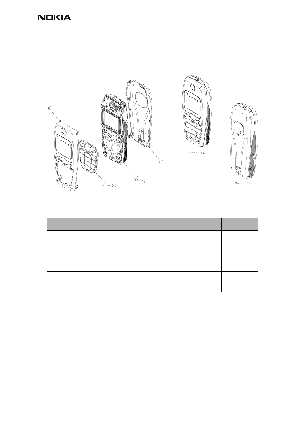
Remove A-cover
Place thumb under the edge of the A-cover and fingers on top of the A-cover, then pull
gently until it snaps. Once lifted, ensure that the keymat does not fall out of the A-cover.
Remove screws
Unscrew the six screws as indicated.
3
1
2
6
Page 6 Nokia Corporation Confidential Issue 1 05/2003
Page 65

RH-14
CCS Technical Documentation Disassembly/Assembly
Remove lightguide assembly
Follow the steps indicated in the following diagram:
Remove metal frame and earpiece
Follow the numbered steps in the following diagram.
Note: Use screwdriver size 2.50 – 3.50 mm.
1 Turn screwdriver at snaps only on one side
2 When removing the metal frame, be careful not to damage the four springs in
the corners
3 Remove earpiece
Issue 1 05/2003 Confidential Nokia Corporation Page 7
Page 66

RH-14
1
LED
Disassembly/Assembly CCS Technical Documentation
b
1a
2
3
Remove PWB assembly
Lift the PWB as indicated in the following drawing. Then, place the PWB on ESD table
with LEDs on top.
Page 8 Nokia Corporation Confidential Issue 1 05/2003
Page 67

RH-14
CCS Technical Documentation Disassembly/Assembly
Remove shielding lids
Caution: Do not re-use shielding lid once it is removed.
When working with the PWB, always use a repair jig.
Remove components from D-cover assembly
The following components are removable:
1Power key
2 Battery connector
3 SALT speaker (see diagram)
4Vibra
5 Bottom connector
Issue 1 05/2003 Confidential Nokia Corporation Page 9
Page 68

RH-14
Disassembly/Assembly CCS Technical Documentation
SALT speaker
Page 10 Nokia Corporation Confidential Issue 1 05/2003
Page 69

RH-14
CCS Technical Documentation Disassembly/Assembly
Step-by-Step Assembly Guide
Mount components in D-cover
1Power key
2 Battery connector
3SALT speaker
4Vibra
5 Bottom connector
Note: Ensure that all components are placed correctly.
Issue 1 05/2003 Confidential Nokia Corporation Page 11
Page 70

RH-14
Disassembly/Assembly CCS Technical Documentation
Mount shielding lids on PWB
Mount PWB on D-cover
Mount earpiece and metal frame
1 Mount the earpiece in the lightguide
2 Place metal frame on lightguide — be careful about the springs in each of the
four corners
3 Push the metal frame down (indicated with arrows in drawing below) until it
snaps on
Page 12 Nokia Corporation Confidential Issue 1 05/2003
Page 71

RH-14
CCS Technical Documentation Disassembly/Assembly
Mount domesheet
When mounting the domesheet, use the two holes indicated as guide.
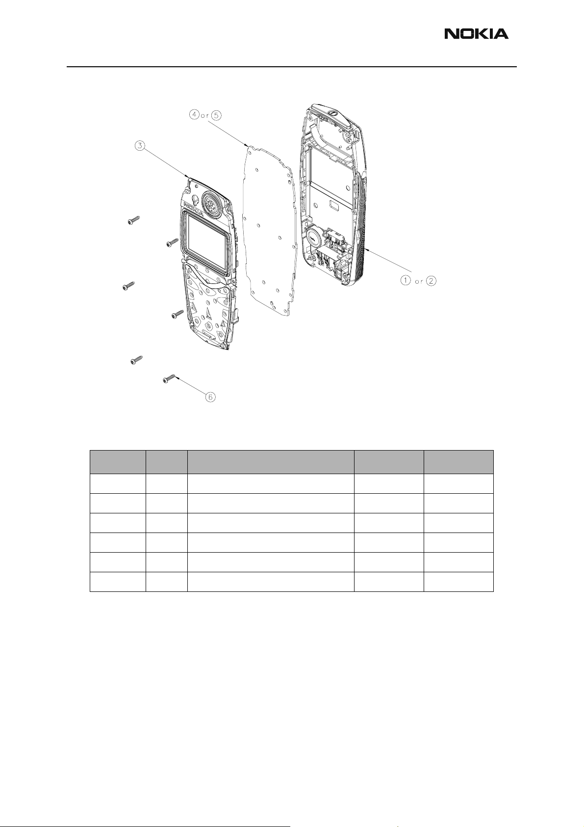
Mount display assembly on D-cover
1 Place the display assembly in the D-cover
2 Push the display assembly down (indicated by arrows in the drawing below) until
it snaps on
Issue 1 05/2003 Confidential Nokia Corporation Page 13
Page 72

RH-14
5
4
Disassembly/Assembly CCS Technical Documentation
Mount screws
Fasten the screws in the sequence indicated in the following diagram. Be sure to use a
torx #6 screwdriver.
Note: Max torque 28Ncm at 500-600RPM.
3
Mount keymat and A-cover assembly
1
2
6
1 Place keymat
2 Push down the A-cover until it snaps on
Page 14 Nokia Corporation Confidential Issue 1 05/2003
Page 73

RH-14
CCS Technical Documentation Disassembly/Assembly
Insert RF Plug
Insert RF Plug into RF connector opening in the antenna.
Issue 1 05/2003 Confidential Nokia Corporation Page 15
Page 74

RH-14
Disassembly/Assembly CCS Technical Documentation
Place battery
Slide battery under the hooks in the D-cover.
Mount B-cover assembly
1 Place B-cover assembly on D-cover
2 Push the B-cover in the direction indicated by the arrow in drawing below until
the B-cover snaps on
Page 16 Nokia Corporation Confidential Issue 1 05/2003
Page 75

CCS Technical Documentation
RH-14 Series Transceivers
Troubleshooting
Issue 1 05/2003 Confidential Nokia Corporation
Page 76

RH-14
Troubleshooting CCS Technical Documentation
Page 2 Nokia Corporation Confidential Issue 1 05/2003
Page 77

RH-14
CCS Technical Documentation Troubleshooting
Contents
Page No
Troubleshooting............................................................................................................. 5
Baseband Troubleshooting ..........................................................................................5
General testing information....................................................................................... 5
Troubleshooting ........................................................................................................ 5
Phone does not start up normally or does not stay on............................................... 8
Flash Programming does not work.......................................................................... 10
Charging.................................................................................................................. 12
Audio failures.......................................................................................................... 13
Accessory detection................................................................................................. 15
Sleep Clock ............................................................................................................. 16
User Interface.......................................................................................................... 18
Receiver Troubleshooting ..........................................................................................20
General Instructions for RX troubleshooting.......................................................... 20
Path of the received signal ...................................................................................... 20
Fault-finding charts for receiver chain.................................................................... 21
Transmitter fault-finding ...........................................................................................28
General instructions for TX troubleshooting .......................................................... 28
Path of the transmitted signal.................................................................................. 28
Fault-finding charts for transmitter......................................................................... 28
Power control loop.................................................................................................. 31
Synthesizer fault-finding ...........................................................................................34
19.44 MHz reference oscillator............................................................................... 34
RX VHF VCO......................................................................................................... 36
TX VHF VCO......................................................................................................... 37
UHF Synthesizer..................................................................................................... 37
Issue 1 05/2003 Confidential Nokia Corporation Page 3
Page 78

RH-14
Troubleshooting CCS Technical Documentation
Page 4 Nokia Corporation Confidential Issue 1 05/2003
Page 79

RH-14
CCS Technical Documentation Troubleshooting
Troubleshooting
The first thing to do when a problem is encountered is to carry out a thorough visual
check of the module. Make sure that:
• there are no mechanical damages
• the solder joints are OK
Note: Before changing anything, ALL SUPPLY VOLTAGES AND THE SYSTEM CLOCK / SLEEP
CLOCK should be checked.
Baseband Troubleshooting
General testing information
There are three different modes for testing and/or repairing the phone. The mode can be
selected with suitable resistors connected to BSI- and BTEMP- lines as illustrated in the
following table:
Table 1: Phone operating mode
Mode BSI- resistor
Normal 68k 75k
Local 560_(<1k_) Whatever
Test > 1k 560_(<1k_) Recommended for baseband testing. Same as local
BTEMP
resistor
Remarks
mode, but making a phone call is possible.
If the corresponding resistors are connected, the MCU software automatically enters into
the local or test mode when the supply voltage is connected to the phone.
The power can be switched on by:
1 Pressing the power key.
2 Connecting the local/test mode resistors to the BSI/BTEMP lines and connecting
the battery voltage to the phone.
3 Connecting a charger.
4 Using the phone’s internal functions (real-time clock alarm).
In the local and test mode, the baseband can be controlled through MBUS or FBUS (FBUS
is recommended) connections using Phoenix service software.
Troubleshooting
Note: Most of the baseband repair actions require removing the baseband shield. The shield must not
be removed unless separately authorized by the program.
Issue 1 05/2003 Confidential Nokia Corporation Page 5
Page 80

RH-14
Troubleshooting CCS Technical Documentation
Note: The phone’s ESN has to re-written to the UEM, if the UEM is replaced. This can be done only in
Central Service.
The baseband troubleshooting instructions include the following topics:
1Power up
2 Flash programming
3Audio
• Earpiece
• Microphone
4 Charging
5 Accessory detection
6Sleep clock
7 User interface
Power-up faults
Power-up sequence
1 The UEM acts as a HW master during start up
• Vbatt limits: 2.1V for internal state machine, 3V triggering whole startup
•Display
•Lights
•MIDI
•Vibra
• Keyboard
• Regulator sequencing
• HW "core" regulators "on": Vio, Vcore, VR3, Vflash1
• These regulators supply the processors, memory chip interfaces
and clock source in RF
• Reset releasin g del ay
Page 6 Nokia Corporation Confidential Issue 1 05/2003
Page 81

RH-14
CCS Technical Documentation Troubleshooting
• Supply voltages stabilize to their UEM HW default values
• RFCLK grows to full swing
• The core is ready to run but waiting for the PURX release
• Reset releasing
• The UPP releases the SLEEPX up to the "non sleep" state to prevent the UEM switching the regulators "OFF"
2 MCU starts running the Bootstrap Code
• written in stone/ UPP internal ROM
• the program checks if there is any reason for the FDL mode (Flash
Down Load)
• If there is an executable code in FLASH and there is no reason for
FDL, the MCU starts running the MCU program from FLASH
3 MCU runs the FLASH MCU code
• the phone initialization, user interfaces, internal blocks, etc.
• Core regulator voltage setting for required DSP speed
• Initializes the DSP and concerning HW
• Releases DSP reset -> DSP starts running
Note: In the following figure, the RF_Clk frequency appears to be lower than 19.44MHz because of a
too low oscilloscope sampling frequency (2kS/s).
Issue 1 05/2003 Confidential Nokia Corporation Page 7
Page 82

RH-14
Troubleshooting CCS Technical Documentation
Figure 1: Power-up sequence
1 Power key pressed
• After 20ms, UEM enters RESE T MODE if VBAT>Vmstr+
• VFLASH1, Vana, Vcore, Vio, and VR3 goes high
• VCTCXO enabled by VR3 -> RFClk 19.44 MHz running
2 Purx released
• Purx released by UEM, UEMINT goes high for 100 ms, SleepX
goes high, and SleepClk (32 KHz) starts running.
3 Software running
• Default value for Vcore is 1.5 volts and, if software is running, Vcore
will rise to 1.8 volts
• Cbus (1.08MHz) and Dbus clocks start running
Phone does not start up normally or does not stay on
Note: In the case of power-up faults, it is not possible to force the phone on by disabling the watchdog.
Instead, measurements should be taken immediately when the power key is pressed or when the battery voltage is connected to the phone (local / test mode).
The easiest way to check if the software is running when the phone takes an abnormal
amount of current is to measure the cbusclk and Vcore.
The Dbus clock (programmable 9.72MHz) is not automatically visible in the test and local
modes.
Page 8 Nokia Corporation Confidential Issue 1 05/2003
Page 83

RH-14
CCS Technical Documentation Troubleshooting
Figure 2: Fault tree, phone does not power up
Issue 1 05/2003 Confidential Nokia Corporation Page 9
Page 84

RH-14
Troubleshooting CCS Technical Documentation
Flash Programming does not work
Flash programming procedure
1 The phone communicates with the prommer via the production test pattern,
using the following signals:
• FBUSTX (serial data to phone)
• FBUSRX (serial da t a from phon e)
• MBUS (serial clock for FBUSRX)
• VPP (External flashing voltage for speed up flashing)
• The BSI line is also used when initializing flashing (battery connector)
2 When the phone is powered (VBAT>3V), the MBUS and FBUSTX lines are pulled
up internally by the phone.
3 The prommer sends a command to the UEM, using FBUSRX, to enter the Flash-
mode. During the sending of this command, the prommer keeps the BSI line high
and MBUS is used as a serial clock.
4 When the Flash-mode command is acknowledged, UEM enters the Flash-mode
and releases reset (PURX) to MCU.
5 After reset is released, UPP checks if there is a request for the Bootstrap code
(that resides in the UPP ROM).
6 The request for Bootstrap is the MBUS pulled down by the prommer (if the boot-
strap is not requested, the bootstrap code jumps to FLASH SW).
7 If the Bootstrap code is requested, UPP enters the Flash-mode and sets FbusTX to
'0' as an acknowledgement to the prommer. This is an indication that UPP can
run, at least, the fixed Bootstrap code – although it is not able to run the FLASH
code. UPP then sends an UPP-ID to the prommer via the FBUSTX line.
8 After the prommer has received the UPP-ID, it sends a corresponding Secondary
Boot Code to the phone via FBUSRX. The Secondary Boot Code, when run in UPP,
requests UPP to send information to the prommer about the flash type and other
HW-related parameters about the device to be flashed.
9 The prommer then sends the Algorithm Code corresponding to the HW parame-
ters, and this algorithm, when run in UPP, takes over handling the MCUSW transfer to Flash.
10 12 volts can be supplied to Vpp (by the prommer) to speed up flashing.
Page 10 Nokia Corporation Confidential Issue 1 05/2003
Page 85

RH-14
CCS Technical Documentation Troubleshooting
11 The FLASH Program includes a package of MCU and DSP software and all default
parameters for the phone. The tuning values will be added/rewritten during the
Flash/Alignment phase.
Flash programming error codes
The various error codes can be seen from the "FPS-8 Flash" in Phoenix.
The underlined text in the following table means that the item under consideration is
being used for the first time in the flashing sequence.
Error Description Not working properly
C101 "The Phone does not set FbusTx line high after the star-
tup."
C102 "The Phone does not set FbusTx line low after the line
has been high. The Prommer generates this error also
when the Phone is not connected to the Prommer."
C103 "Boot serial line fail." Mbus from Prommer->UEM-
C104 "MCU ID message sending failed in the Phone." FbusTx from UPP->UEM->Prommer
C105 "The Phone has not received Secondary boot codes
length bytes correctly."
Vflash1
VBatt
BSI and FbusRX from prommer to UEM.
FbusTx from UPP->UEM->Prommer(SA0)
PURX(also to Safari)
VR3
Rfclock(VCTCXO->Safari->UPP)
Mbus from Prommer->UEM>UPP(MbusRx)(SA0)
FbusTx from UPP->UEM->Prommer(SA1)
BSI and FbusRX from prommer to UEM.
>UPP(MbusRx)(SA1)
FbusRx from Prommer->UEM->UPP
FbusTx from UPP->UEM->Prommer
Mbus from Prommer->UEM>UPP(MbusRx)
FbusRx from Prommer->UEM->UPP
FbusTx from UPP->UEM->Prommer
C106 "The Phone has not received Secondary code bytes cor-
rectly."
C107 "The Phone MCU can not start Secondary code cor-
rectly."
C586 "The erasing status response from the Phone informs
about fail."
C686 "The programming status response from the Phone
informs about fail."
Cx81 "The Prommer has detected a checksum error in the mes-
sage, which it has received from the Phone."
Mbus from Prommer->UEM>UPP(MbusRx)
FbusRx from Prommer->UEM->UPP
FbusTx from UPP->UEM->Prommer
UPP
Flash
Flash
FbusTx from UPP->UEM->Prommer
Issue 1 05/2003 Confidential Nokia Corporation Page 11
Page 86

RH-14
Troubleshooting CCS Technical Documentation
Cx82 "The Prommer has detected a wrong ID byte in the mes-
sage, which it has received from the Phone."
A204
Cx83
Cx84
Cx85
Cx87 "Wrong MCU ID." RFClock
Startup
for
flashing
"The flash manufacturer and device IDs in the existing
Algorithm files do not match with the IDs received from
the target phone."
"The Prommer has not received Phone acknowledge to
the message."
"The Phone has generated NAK signal during data block
transfer."
"Data block handling timeout"
Required startup for flashing Vflash1
FbusTx from UPP->UEM->Prommer
Flash
UPP
VIO/VANA?
Signals between UPP-Flash
Mbus from Prommer->UEM>UPP(MbusRx)
FbusRx from Prommer->UEM->UPP
FbusTx from UPP->UEM->Prommer
UPP(Vcore)
VBatt
Charging
Note: The charging voltage and current can be checked by connecting the phone to the service software and reading the ad- converter values of the vchar and ichar.
If charging fails when the ACP-9 or the LCH-9 is used, but works with ACP-7, ACP-8, and
LCH-8, check that the charge control pin of the system connector is connected to the
ground.
Page 12 Nokia Corporation Confidential Issue 1 05/2003
Page 87

RH-14
CCS Technical Documentation Troubleshooting
Figure 3: Fault tree, charging
Audio failures
In case of audio failures, there are three possibilities to check the audio lines.
1 Make a phone call against tester and check audios.
2 If the earpiece/XMIC fails: Feed a 1Khz signal to the XMIC line and measure the
signal from the earpiece line. The Audio test box JBA-8 is needed. The Audio loop
(Audio test/Ext In Hp Out) must be switched on by the Phoenix service software.
This loop will connect audios only through the UEM. In this case, the UPP is not
used.
If the internal microphone/XEAR fails: Feed the tone to the microphone and measure the signal from the XEAR line. The Audio test box JBA-8 is needed. The
Audio loop (Audio test/Hp In Ext Out) must be switched on by the Phoenix service
software. This loop will connect audios only through the UEM. In this case, the
Issue 1 05/2003 Confidential Nokia Corporation Page 13
Page 88

RH-14
Troubleshooting CCS Technical Documentation
UPP is not used.
3 Run the audio-loop self-test with Phoenix (BB Self Tests/
ST_EAR_DATA_LOOP_TEST). This loop will test the ear-data/mic-data lines
between the UPP and the UEM.
Earpiece or external microphone line does not work
Figure 4: Fault tree, earpiece failure
Page 14 Nokia Corporation Confidential Issue 1 05/2003
Page 89

RH-14
CCS Technical Documentation Troubleshooting
Microphone or XEAR line does not work
Figure 5: Fault tree, microphone failure
Accessory detection
1 Start the phone in the normal mode when checking for accessory detection.
2 The Ad-converter value of the hookint-line can be checked with the Xmic switch
on an MJ-8 test jig. Changes normally from high to low when no accessory is
connected.
3 When the headset HDC-5 is connected, the hookint-value should be between
600 and 800.
Issue 1 05/2003 Confidential Nokia Corporation Page 15
Page 90

RH-14
Troubleshooting CCS Technical Documentation
Figure 6: Fault tree, accessory detection
Sleep Clock
Missing/nonfunctional sleep clock causes
• Entering sleep mode fails (higher current consumption -> shorter
standby time)
• Baseband self-tests cannot be run
• Phone clock (on display) does not function properly
Page 16 Nokia Corporation Confidential Issue 1 05/2003
Page 91

RH-14
CCS Technical Documentation Troubleshooting
Figure 7: Fault tree, sleep clock
Issue 1 05/2003 Confidential Nokia Corporation Page 17
Page 92

RH-14
Troubleshooting CCS Technical Documentation
User Interface
Display/Keyboard lights do not work
Figure 8: Fault tree, Display/Keyboard lights
Page 18 Nokia Corporation Confidential Issue 1 05/2003
Page 93

RH-14
CCS Technical Documentation Troubleshooting
Display does not work
Figure 9: Fault tree, Display does not work
Issue 1 05/2003 Confidential Nokia Corporation Page 19
Page 94

RH-14
Troubleshooting CCS Technical Documentation
MIDI does not work
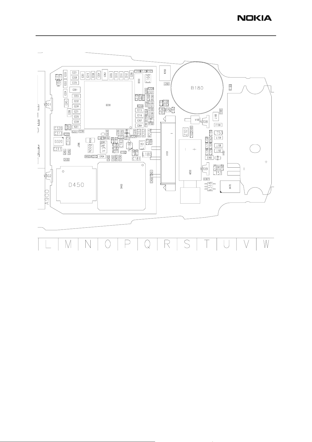
Check speaker B180 and the following components: N180, R100, R181, R182, R183,
R184, C183, C180, C184, C181, C182, C179, L180, and L181
• No sound: Try using a known good SAL T speaker instead. If there is still
no sound, change the UEM (D200)
• Weak sound: Use the Audio test in Phoenix to set the SALT speaker
parameters (frequency, strength). If it does not affect the sound level,
change the SALT speaker.
Vibra does not work
Check spring connectors and C307 and C308.
• No vibration: Try using a known good vibra instead. If there is still no
vibration, change the UEM (D 200)
• Weak vibration: Use the Vibra test in Phoenix to set the vibra’s parameters (frequency, duty cycle). If it does not affect the magnitude of the
vibration, change the vibra.
Keyboard does not work
Check that there is no dirt between the dome sheet and the PWB. If the keyboard still
does not operate normally, try to use the Keyboard test in Phoenix to see if the pressed
key is identified. If it is not identified, change the UPP (D400).
Receiver Troubleshooting
General Instructions for RX troubleshooting
Start the Phoenix software and use it to start the required RX mode of the mobile phone.
The troubleshooting flowchart is divided into three steps: (1) general checking, (2) local
checking, and (3) RX-chain checking. Always use an RF cable connected from an external
RF connector to the analyzer via (RF power) attenuator. This is important to protect the
analyzer against excessive RF power and to prevent leakage of undesired RF power into
the cellular frequencies.
1 Start the Phoenix software and select the TX mode under Testing (AMPS, DAMPS,
or TDMA1900).
2 It is useful to select the mid channel (383 for AMPS/DAMPS or 1000 for
TDMA1900) and the power level 2.
Note: Before changing ASICs or filters, all solderings and missing components must be checked visually. After any possible component changes, the phone must be tuned with the Phoenix autotune SW.
Path of the received signal
Block level description of the receiver:
Page 20 Nokia Corporation Confidential Issue 1 05/2003
Page 95

RH-14
CCS Technical Documentation Troubleshooting
(Antenna/ext RF) – Diplexer – Duplexer – Low Noise Amplifier (LNA) – RX band filter –
First mixer – 135.54 MHz RX IF filter – IF-amplifier – second mixer – 14 kHz low-pass filter – adjustable IQ amplifier – Baseband.
Fault-finding charts for receiver chain
AMPS
Figure 10: Fault tree, AMPS
Issue 1 05/2003 Confidential Nokia Corporation Page 21
Page 96

RH-14
Troubleshooting CCS Technical Documentation
Page 22 Nokia Corporation Confidential Issue 1 05/2003
Page 97

RH-14
d
CCS Technical Documentation Troubleshooting
Check RF level at RX
IF filter input at 135.54
MHz
Y
Check RF level at RX
IF filter output at
135.54 MHz
Y
N
Check RF level at J 751
and J752 at 2034.06
MHz
Y
Change SAFARI
(N801)
N
Change RX IF f i lter
(Z830)
N
Start synthesizer
troubleshoot
Note !
Check all discr et e c omp onents an
voltages ar ound S AFARI
Check RX I and Q
signals at I: J801(+),
J803(-) and Q:
J804(+), J802(-)
Y
Check UEM and start
baseband troubles hoot
N
Check RF level by
L730 without having
electrical co nt ac t at
271.08 MHz
Change SAFARI
(N801)
N
Start synthesizer
troubleshoot
Y
Issue 1 05/2003 Confidential Nokia Corporation Page 23
Page 98

RH-14
Note!
g
Troubleshooting CCS Technical Documentation
TDMA800
Since the same physical signal path is used for both analog and digital modes at the
lower band, there is no need for additional troubleshooting in the digital mode. So if the
digital mode at the lower band is not working properly, start the analog mode troubleshooting.
TDMA1900 (only dualband)
Only EXT RF connector –> 1
st IF needs separate troubleshoot at upper band. After down
conversion (RF –> 135.54 MHz), both lower and upper band use the same signal path.
Figure 11: Fault tree, TDMA1900 troubleshooting
Apply 1960.02 MH z =
ch 1000 -110 dBm
signal to external
RF-connector X900.
Y
Enable loop back BE R
using RF Test UI and
check sensitivity: -110
dBm BER < 3%
N
N
Check UHF Vc (from
C773) V: 2. 2 . ..2.6 V
Y
Y
N
N
TDMA1900
RX-chain is OK
Start synthesizer
troubleshooting
These tests are done
in local mode by usin
RF Test UI.
Check RXVHF Vc
(from C720). V: 0.7
...1.3
Y
Start synthesizer
troubleshooting
Page 24 Nokia Corporation Confidential Issue 1 05/2003
Page 99

RH-14
CCS Technical Documentation Troubleshooting
Issue 1 05/2003 Confidential Nokia Corporation Page 25
Page 100

RH-14
Troubleshooting CCS Technical Documentation
Table 2: Flash programming error codes
Error Description Not working properly
C101 "The Phone does not set FbusTx line high after the star-
tup."
C102 "The Phone does not set FbusTx line low after the line
has been high. The Prommer generates this error also
when the Phone is not connected to the Prommer."
C103 "Boot serial line fail." Mbus from Prommer->UEM-
C104 "MCU ID message sending failed in the Phone." FbusTx from UPP->UEM->Prommer
C105 "The Phone has not received Secondary boot codes
length bytes correctly."
Vflash1
VBatt
BSI and FbusRX from prommer to UEM.
FbusTx from UPP->UEM->Prommer(SA0)
PURX(also to Safari)
VR3
Rfclock(VCTCXO->Safari->UPP)
Mbus from Prommer->UEM>UPP(MbusRx)(SA0)
FbusTx from UPP->UEM->Prommer(SA1)
BSI and FbusRX from prommer to UEM.
>UPP(MbusRx)(SA1)
FbusRx from Prommer->UEM->UPP
FbusTx from UPP->UEM->Prommer
Mbus from Prommer->UEM>UPP(MbusRx)
FbusRx from Prommer->UEM->UPP
FbusTx from UPP->UEM->Prommer
Page 26 Nokia Corporation Confidential Issue 1 05/2003
 Loading...