

Page 1

Customer Care Solutions
TME-3 Series Transceivers
Service T ools
Issue 3 10/03 Copyright Nokia. All rights reserved.
Page 2

TME-3
Service Tools CCS Technical Documentation
[This page intentionally left blank.]
Page 2 Copyright Nokia. All rights reserved. Issue 3 10/03
Page 3

TME-3
CCS Technical Documentation Service Tools
Table of Contents
Page No
General Instructions....................................................................................................... 4
XRC-5 RF Cable ..........................................................................................................5
Product code............................................................................................................. 5
JBV-1 Docking Station and MJF-21 Adapter .............................................................6
Product Code:............................................................................................................ 6
Product Code:............................................................................................................ 7
MJF-21 & JBV-1 setup............................................................................................. 7
FLA-34 Flashing Adapter ............................................................................................8
Product Code............................................................................................................. 8
FLA-34 setup............................................................................................................. 8
MJS-63 Module Jig ......................................................................................................9
Product Code............................................................................................................. 9
MJS-63 setup........................................................................................................... 10
MJS-62 Soldering Jig ................................................................................................11
Product Code........................................................................................................... 11
FPS-8 Flash Prommer (Sales Pack) ...........................................................................12
Sales package code.................................................................................................. 12
ACS-10 Power supply module for FPS-8 ..................................................................13
Product Code........................................................................................................... 13
FPS-8C Parallel Flash Prommer (Sales Pack) ...........................................................14
Sales package code.................................................................................................. 14
ACF-8 Universal Power Supply ................................................................................15
Product Code........................................................................................................... 15
AXS-4 Service Cable .................................................................................................16
Product code........................................................................................................... 16
SW Security Device PKD-1 .....................................................................................17
Product Code........................................................................................................... 17
FLS-4S POS (Point Of Sale) Flash Device (Sales Pack) .........................................18
Product Code........................................................................................................... 18
POS Flash setup ...................................................................................................... 18
PCS-1 Power Cable ...................................................................................................19
Product Code........................................................................................................... 19
DAU-9S MBUS Cable ..............................................................................................20
Product Code........................................................................................................... 20
XCS-4 Modular Cable ...............................................................................................21
Product code........................................................................................................... 21
Parallel Cable CA-10 DS ...........................................................................................22
Product code........................................................................................................... 22
SB-1 Service Box for TME-3 ....................................................................................23
Product code............................................................................................................ 23
DTX-3 Nokia 32 Application module .......................................................................24
Product code............................................................................................................ 24
Issue 3 10/03 Copyright Nokia. All rights reserved. Page 3
Page 4

TME-3
Service Tools CCS Technical Documentation
General Instructions
Before connecting the service tools :
Caution:Make sure that you have swithed off the PC and the printer before
making connections!
Caution:Do not connect the PKD-1 key to the serial port. You may damage
your PKD-1!
Page 4 Copyright Nokia. All rights reserved. Issue 3 10/03
Page 5
TME-3
CCS Technical Documentation Service Tools
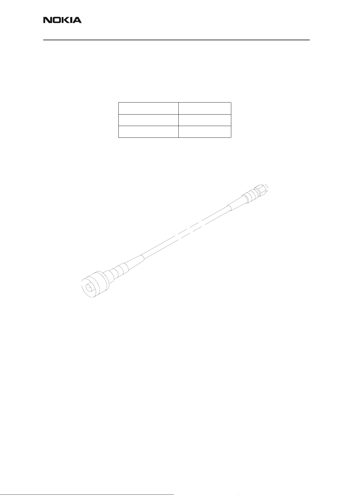
XRC-5 RF Cable
RF cable XRC-5 is used to connect e.g. Module Jig MJS-63 to RF measurement equipment..
Attenuation table:
900 MHz 0.86dB/m
1800 MHz 1.20dB/m
1900 MHz 1.24dB/m
Product code
XRC-5RF Cable: 0730276
Figure 1: View of XRC-5
Issue 3 10/03 Copyright Nokia. All rights reserved. Page 5
Page 6
TME-3
Service Tools CCS Technical Documentation
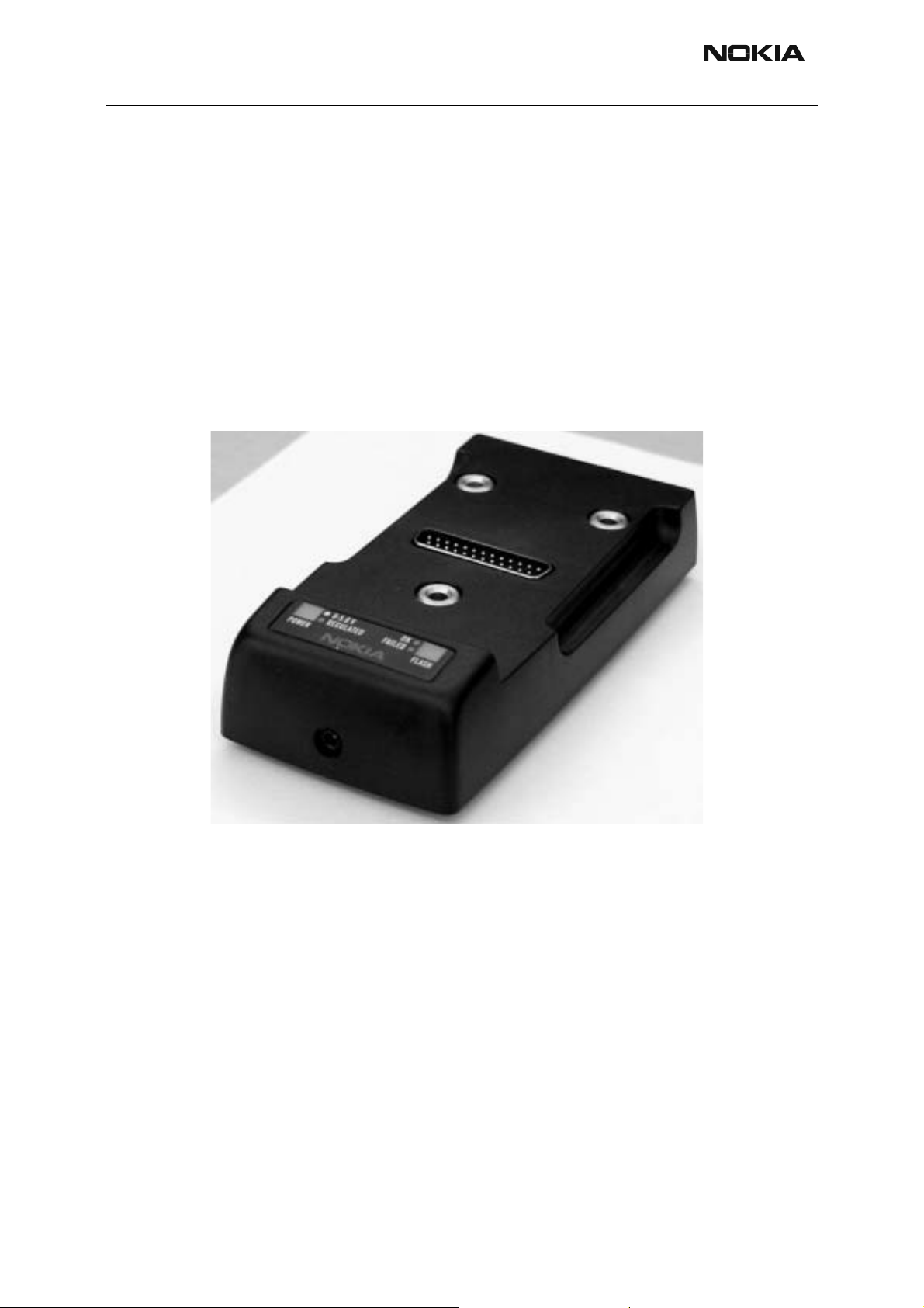
JBV-1 Docking Station and MJF-21 Adapter
The JBV-1 Docking Station has been designed for calibration and software update use.
The MJF-21 Docking Station Adapter makes signal connections to the phone.
JBV-1 and MJF-21 are used as one unit.
In calibration mode JBV-1 is powered by external power supply 11-16VDC. In flashing
operation the power for the phone must be taken from external power supply 11-16VDC.
Product Code:
JBV-1 Docking Station: 0770298
Figure 2: View of JBV-1
Page 6 Copyright Nokia. All rights reserved. Issue 3 10/03
Page 7
TME-3
CCS Technical Documentation Service Tools
Product Code:
MJF-21 Docking Station Adapter: 0770374
Figure 3: View of MJF-21
MJF-21 & JBV-1 setup
1. Attach the protection key PKD-1 to parallel port one (25-pin female D-connector) of
the PC. When connecting the PKD-1 to the parallel port be sure that you insert the PC
end of the PKD-1 to the PC (male side). If you use a printer on parallel port one, place the
PKD-1 between the PC and your printer cable.
2. Connect the printer cable and D9-D9 cable, AXS-4 to the flash prommer, FPS-8.
3. Attach the docking station adadpter, MJF-21, to the docking station, JBV-1.
4. Connect modular cable, XCS-4, from the front panel of FPS-8 to the docking sta tion,
JBV-1.
5. Connect power cable PCS-1, from the front panel of the FPS-8 (4V) to the connector
of JBV-1.
6. Install the TME-3/4 to the docking station adapter, MJF-21.
7. Connect power supply ACF-8 to the FPS-8.
8. Start Phoenix and follow the flashing instructions.
Issue 3 10/03 Copyright Nokia. All rights reserved. Page 7
Page 8
TME-3
Service Tools CCS Technical Documentation
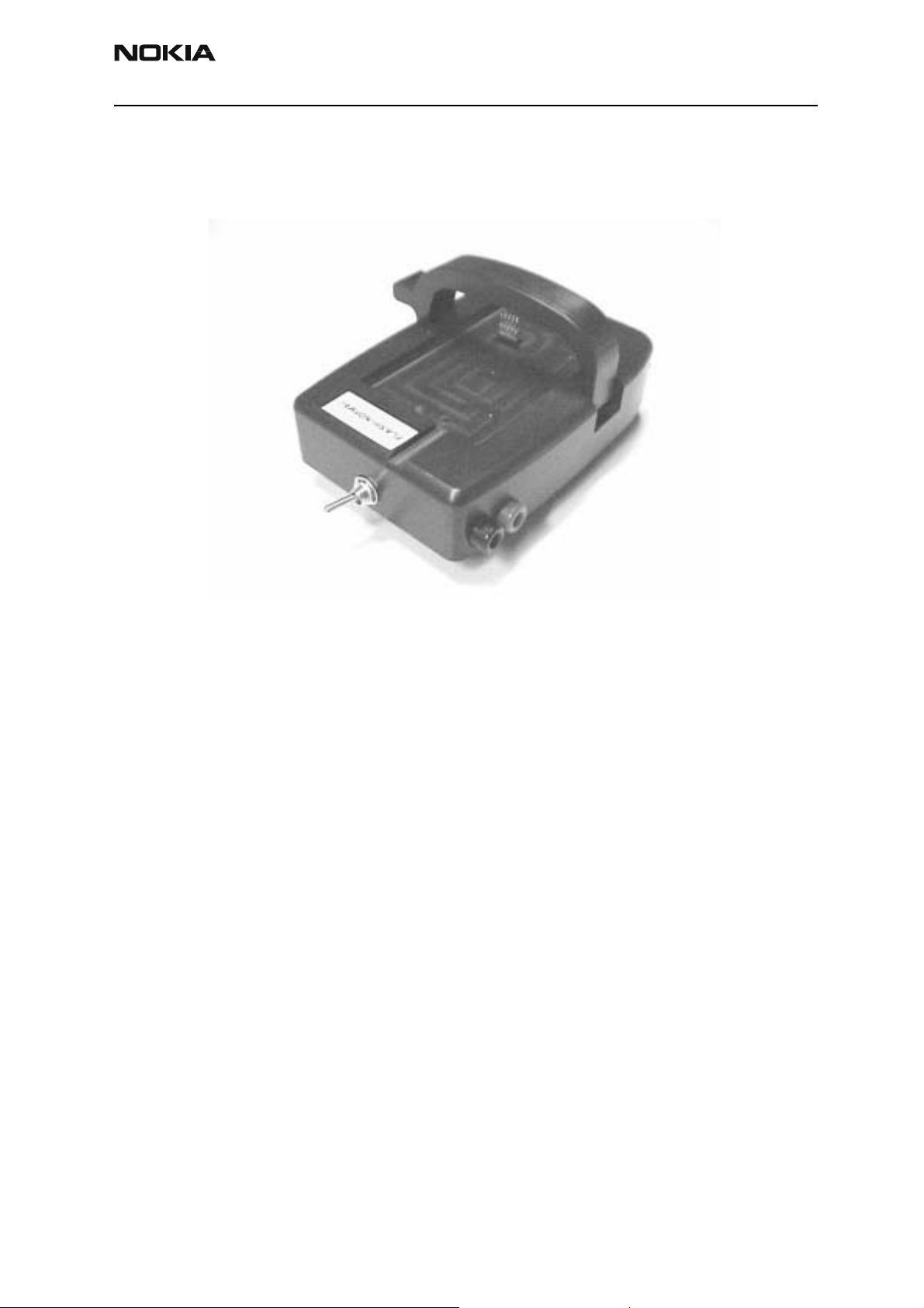
FLA-34 Flashing Adapter
The FLA-34 Flashing adapter is used for reflashing the TME-3 in a service center.
Product Code
FLA-34 Flashing Jig: 0770375
Figure 4: View of FLA-34
FLA-34 setup
1. Attach the protection key PKD-1 to parallel port one (25-pin female D-connector) of
the PC. When connecting the PKD-1 to the parallel port be sure that you insert the PC
end of the PKD-1 to the PC (male side). If you use a printer on parallel port one, place the
PKD-1 between the PC and your printer cable.
2. Connect the printer cable and D9-D9 cable, AXS-4 to the flash prommer, FPS-8.
3. Connect modular cable, XCS-4, from the front panel of FPS-8 to the fla s h adapter,
FLA-34.
4. Connect power cable, PCS-1, from the rear panel of the FPS-8 (ACS-10) or external
power supply (8,5V) to the connector of FLA-34.
5. Install the TME-3/4 to the flash adapter, FLA-34.
6. Connect power supply ACF-8 to the FPS-8.
7. Start Phoenix and follow the flashing instructions.
Page 8 Copyright Nokia. All rights reserved. Issue 3 10/03
Page 9

TME-3
CCS Technical Documentation Service Tools
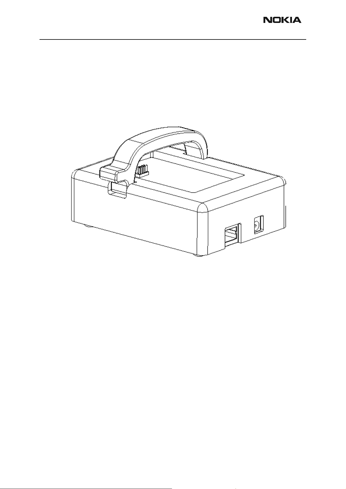
MJS-63 Module Jig
The MJS-63 Module Jig is used for testing of system/RF-module.
Product Code
MJS-63 Module Jig: 0770377
Figure 5: View of MJS-63
*Note: The nominal supply voltage for MJS-63 is +8.0 V.
The supply voltage must not exceed +12.0 V (min 5V). (MJS-63 has overvoltage protec-
tion)
For flashing with FPS-8, it is possible to bypass the regulator(jumper).
Issue 3 10/03 Copyright Nokia. All rights reserved. Page 9
Page 10

TME-3
Service Tools CCS Technical Documentation
MJS-63 setup
1. Attach the protection key PKD-1 to parallel port one (25-pin female D-connector) of
thePC. When connecting the PKD-1 to the parallel port be sure that you insert the PC
end of the PKD-1 to the PC (male side). If you use a printer on parallel port one, place the
PKD-1 between the PC and your printer cable.
2. Connect the printer cable and D9-D9 cable, AXS-4 to the flash prommer, FPS-8.
3. Connect modular cable, XCS-4, from the front panel of FPS-8 to the module jig, MJS-
63.
4. Connect power cable, PCS-1, from the rear panel of the FPS-8 (ACS-10) or external
power supply (8,5V) to the connector of MJS-63.
5. Install the RL7/8 module to the module jig, MJS-63.
6. Connect power supply ACF-8 to the FPS-8.
7. Start Phoenix and follow the flashing instructions.
Page 10 Copyright Nokia. All rights reserved. Issue 3 10/03
Page 11

TME-3
CCS Technical Documentation Service Tools
MJS-62 Soldering J ig
The Soldering Jig MJS-62 is used for soldering and as a rework jig for system module.
Product Code
MJS-62 Soldering Jig: 0770376
Figure 6: View of MJS-62
Issue 3 10/03 Copyright Nokia. All rights reserved. Page 11
Page 12

TME-3
View of FPS-8
Service Tools CCS Technical Documentation
FPS-8 Flash Prommer (Sales Pack)
The Flash Prommer FPS-8 is used with e.g. FLA-63 and JBV-1. Power is supplied to FPS-8
from a ACF-8 type Power Supply. Also refer to ACS-10 .
The sales pack includes:
- FPS-8 Flash Prommer 0750123
- FPS-8 Activation Sheet 9359289
- ACF-8 Power Supply 0680032
- AXS-4 Serial Cable (D9-D9) 0730090 (for PC COM port)
- Centronics Cable 0730029 (for PC parallel port)
- CA-10 DS Cable 0730298
Sales package code
- CD-ROM(user guide and installation SW) 0774271
FPS-8 Flash Prommer: 0080321
Figure 7: View of FPS-8
Page 12 Copyright Nokia. All rights reserved. Issue 3 10/03
Page 13

TME-3
CCS Technical Documentation Service Tools
ACS-10 Power supply module for FPS-8
ACS-10 power supply module replaces the original rear panel of the FPS-8. ACS-10 is
needed when programming TME-3.
Installation instructions are included in the FPS-8 Flashing User Guide.
Product Code
ACS-10 Power Supply Module: 0770340
Figure 8: ACS-10 inside
Figure 9: ACS-10 rear panel
Issue 3 10/03 Copyright Nokia. All rights reserved. Page 13
Page 14

TME-3
Service Tools CCS Technical Documentation
FPS-8C Parallel Flash Prommer (Sales Pack)
The Parallel Flash Prommer FPS-8C is used with MJF-6 and JBV-1. Flash programming
can be done to maximum of 8 phones parallel. FPS-8C consists of eight SF11C programming cards. SF11C card is functionally identical to FPS-8.
Sales package code
FPS-8C Parallel Flash Prommer: 0080396
Figure 10: View of FPS-8C
Page 14 Copyright Nokia. All rights reserved. Issue 3 10/03
Page 15

TME-3
CCS Technical Documentation Service Tools
ACF-8 Universal Power Supply
ACF-8 Universal Power Supply is used to power FPS-8. ACF-8 has 6 V DC and 2.1 A output.
Product Code
ACF-8 Universal Power Supply: 0680032
Figure 11: View of ACF-8
Issue 3 10/03 Copyright Nokia. All rights reserved. Page 15
Page 16

TME-3
Service Tools CCS Technical Documentation
AXS-4 Service Cable
The AXS-4 D9-D9 Service Cable is used to connect two 9 pin D connectors e.g. between
PC and FPS-8. Cable length is 2 meters.
Product code
AXS-4 D9-D9 Service Cable: 0730090
Figure 12: View of AXS-4
Page 16 Copyright Nokia. All rights reserved. Issue 3 10/03
Page 17

TME-3
CCS Technical Documentation Service Tools
SW Security Device PKD-1
SW security device is a piece of hardware enabling the use of the service software when
connected to the parallel (LPT) port of the PC. Whithout the dongle present it is not possible to use the service software. Printer or any such device can be connected to the PC
through the dongle if needed.
Caution:Make sure that you have switched off the PC and the printer before making connections!
Caution:Do not connected the PKD-1 to the serial port. You may damage your PKD-1!
Product Code
SW Security Device PKD-1: 0750018
Figure 13: View of SW Security Device
Issue 3 10/03 Copyright Nokia. All rights reserved. Page 17
Page 18

TME-3
View of FLS-4
Service Tools CCS Technical Documentation
FLS-4S POS (Point Of Sale) Flash Device (Sales Pack)
FLS-4S is a dongle and flash device incorporated into one package, developed specifically
for POS use.
Product Code
Sales Pack - Europe/Africa 0080541
Sales Pack -APAC 0080542
Sales Pack -Americas 0080543
Figure 14: View of FLS-4S
POS Flash setup
1. Attach the POS flash adapter FLS-4S to parallel port one (25-pin female D-connector)
of the PC.
2. Connect the modular cable, XCS-4, between the FLS-4S and flash adapter, FLA-34.
3. Connect the power supply ACF-8 to the connector of FLS-4S.
4. Connect the external power supply (8,5V) to the flash adapter, FLA-34.
5. Install the TME-3/4 to the flash adapter, FLA-34.
6. Start Phoenix and follow the flashing instructions.
Page 18 Copyright Nokia. All rights reserved. Issue 3 10/03
Page 19

TME-3
CCS Technical Documentation Service Tools
PCS-1 Power Cable
The PCS-1 Power Cable (DC) is used to connect e.g. JBV-1 to FPS-8.
Product Code
PCS-1 Power Cable: 0730012
Figure 15: View of PCS-1
Issue 3 10/03 Copyright Nokia. All rights reserved. Page 19
Page 20

TME-3
Service Tools CCS Technical Documentation
DAU-9S MBUS Cable
The MBUS Cable DAU-9S has a modular connector, and is used with between PC's serial
port and e.g. Module Jig MJS-63.
Product Code
DAU-9S MBUS Cable: 0730108
Figure 16: View of DAU-9S
Page 20 Copyright Nokia. All rights reserved. Issue 3 10/03
Page 21

TME-3
CCS Technical Documentation Service Tools
XCS-4 Modular Cable
XCS-4 is a shielded cable (one specially shielded conductor) modular cable for flashing
and service purposes.
Product code
XCS-4 Modular Cable: 0730178
Figure 17: View of XCS-4
Issue 3 10/03 Copyright Nokia. All rights reserved. Page 21
Page 22

TME-3
Service Tools CCS Technical Documentation
Parallel Cable CA-10 DS
The 1.8m bidirectional parallel cable is used to connect the PC to FPS-8. IEEE 1284-1944
standard compatible.
Product code
Parallel Cable CA-10DS : 0730298
Figure 18: View of Parallel Cable
Page 22 Copyright Nokia. All rights reserved. Issue 3 10/03
Page 23

TME-3
CCS Technical Documentation Service Tools
SB-1 Service Box for TME-3
The primary physical interface to the application is through the 50-pin M2M System
Connector. The M2M system connector offers serial bus, power input/output, Digital
Audio Interface, analogue audios and remote I/O control.
The 50-pin system connector is connected to the application module with a flat cable
connector. The flat cable is connected to a pin header connector on the customer application. A board-to-board connector that is connected directly to the M2M system connector of the Nokia 30 GSM Connectivity Terminal can also be used in the customer
application.
Product code:
SB-1 Service box: 0770559
Figure 19: SB-1 service box
Issue 3 10/03 Copyright Nokia. All rights reserved. Page 23
Page 24

TME-3
Service Tools CCS Technical Documentation
DTX-3 Nokia 32 Application module
DTX-3 Nokia 32 Application module is used for Nokia 30 final testing (audios).
Product code:
DTX-3 NOKIA 32 AM SWAP PACKAGE: 0046604
Figure 20: DTX-3
Page 24 Copyright Nokia. All rights reserved. Issue 3 10/03
 Loading...