

Page 1

Customer Care Solutions
TME-3 Series Transceivers
T uning, Flashing and Final
T esting Instructions
Issue 3 10/03 Nokia Corporation.
Page 2

TME-3
Tuning, Flashing and Final Testing Instructions PAMS Technical Documentation
[This page left intentionally blank]
Page 2 Nokia Corporation. Issue 3 10/03
Page 3

TME-3
PAMS Technical Documentation Tuning, Flashing and Final Testing Instruc-
Table of Contents
Page No
RF Tuning Instructions .................................................................................................. 5
General .........................................................................................................................5
Flashing concept setup .................................................................................................6
JBV-1 Service Concept ...............................................................................................7
TX tuning, step1: TXIQ tuning ...................................................................................8
Typical values: .......................................................................................................... 9
TX tuning, step2: TXpower level tuning ...................................................................10
RX calibration, step1: Channel select filter ...............................................................12
RX calibration, step2 .................................................................................................13
RX calibration,step3: RX AM suppression ...............................................................14
RX calibration, step4: Band filter ..............................................................................15
Final test instructions for TME-3................................................................................. 16
Needed main equipment: ...........................................................................................16
RF Final test ...............................................................................................................16
Preparation for RF Final test:.................................................................................. 17
Carry out RF Final test............................................................................................ 17
M2M Connector Final test .........................................................................................18
Testing Procedure (TME-3 in Normal Mode without test SIM card):.................... 18
List Of Figures
Page No
Fig 1 Flashing concept.........................................................................................................6
Fig 2 JBV-1 Service Concept ..............................................................................................7
Fig 3 TxIQ tuning window .................................................................................................8
Fig 4 TxIQ tuning ...............................................................................................................9
Fig 5 TX power level tuning window, TxPA high mode ....................................................10
Fig 6 TX power level tuning window, TxPA low mode ....................................................10
Fig 7 Rx channel select filter calibration window ..............................................................12
Fig 8 RX calibration window ..............................................................................................13
Fig 9 RX AM Suppression window ....................................................................................14
Fig 10 Rx Band filter response compensation ....................................................................15
Fig 11 Test set-up ...............................................................................................................16
Fig 12 M2M connector test using SB-1 service box ...........................................................18
Issue 3 10/03 Nokia Corporation. Page 3
Page 4

TME-3
Tuning, Flashing and Final Testing Instructions PAMS Technical Documentation
[This page left intentionally blank]
Page 4 Nokia Corporation. Issue 3 10/03
Page 5

TME-3
PAMS Technical Documentation Tuning, Flashing and Final Testing Instruc-
RF Tuning Instructions
General
All tuning operations of the TME-3 are carried out using the Nokia Phoenix service software. interfaces with TME-3 via service adapter.
The tuning values of the phone are stored on the non-volatile memory of the TME-3.The
contents of this memory can be read by the service software and saved as a file. The program also enables writing the default tuning parameters, in which case all tuning steps
should be carried out.
Issue 3 10/03 Nokia Corporation. Page 5
Page 6
TME-3
Tuning, Flashing and Final Testing Instructions PAMS Technical Documentation
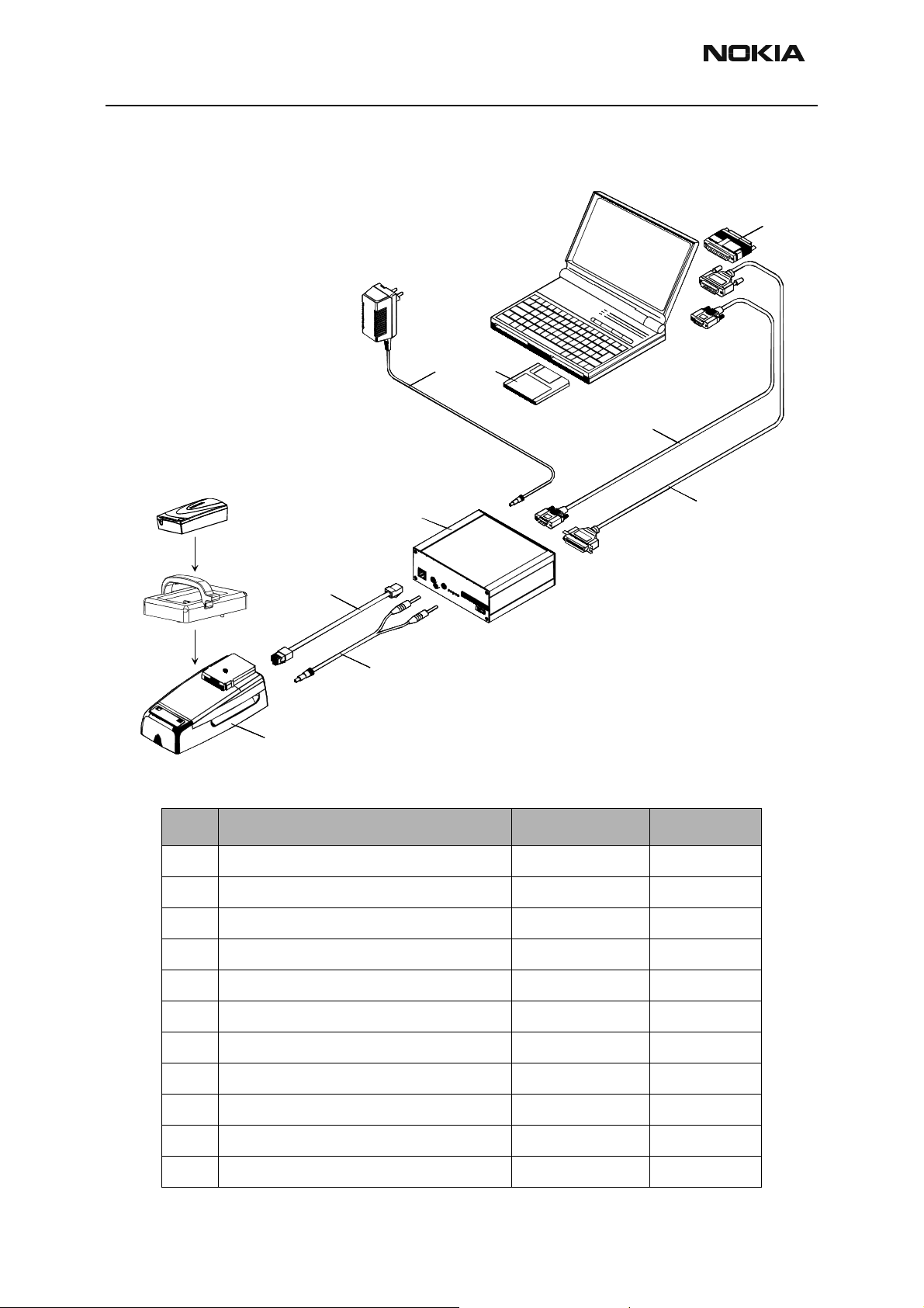
Flashing concept setup
Figure 1: Flashing concept
7
89
6
4
3
2
1
Item: Service accessory: Product type: Product code:
1 Docking station JBV–1 0770298
Docking station adapter MJF–21 0770374
2 Power cable PCS-1 0730012
3 Modular cable XCS–4 07 30178
5
4 Flash prommer box FPS–8 0750123
5 Printer cable, incl. in FPS–8 sales pack Printer cable, 0730029
6 D9 – D9 cable, incl. in FPS–8 sales pack AXS–4 0730090
7 Software protection key PKD–1 0750018
8 Phoenix Service SW CD–ROM 0775311
TME-3 Flash SW data CD–ROM 0775321
9. Power supply ACF-8 0680032
Page 6 Nokia Corporation. Issue 3 10/03
Page 7

TME-3
PAMS Technical Documentation Tuning, Flashing and Final Testing Instruc-
JBV-1 Service Concept
Figure 2: JBV-1 Service Concept
JBV-1 concept list
Item: Service accessory: Type: Product code:
1. Docking stat i on JBV–1 0770298
2. Docking stat i o n adapter MJF–21 0770374
3. Power cable PCS-1 (for external power supply) 0730012
4. Service cable XRC-5 0730276
5. Cable DAU-9S 0730108
6. Software protection key PKD–1 0750018
7. CD–ROM Phoenix Service SW 0774280
CD–ROM TME-3 Flash SW data 0775321
Issue 3 10/03 Nokia Corporation. Page 7
Page 8

TME-3
Tuning, Flashing and Final Testing Instructions PAMS Technical Documentation
TX tuning, step1: TXIQ tuning
Measurement equipment: Spectrum analyzer
Tuning procedure is similar with earlier products.
Select Maintenance => Tuning =>TxIQTuning
Figure 3: TxIQ tuning window
• Select "Load from product" => Start
• Click to slide control to activate it
• Use <-, ->,PgUporPgDnkeys
• Tune LO leak to minimum with TXI/TXQ DC offset control
• Tune wrong sideband to minimum using Amplitude/Phase difference controls
• Select "Save to product" => Stop
• TxIQ tuning must be performed for each band separately
Page 8 Nokia Corporation. Issue 3 10/03
Page 9

TME-3
PAMS Technical Documentation Tuning, Flashing and Final Testing Instruc-
Typical value s :
Figure 4: TxIQ tuning
GS MP OW Thu Aug 30 11: 43: 45 2001
REF 3 2 . 0 d Bm ATT 4 0 d B
10dB/
REF OFS
11. 5 dB
RBW
3kHz
VBW
3kHz
SWP
2. 0 s
CENTER 897. 4000 MHz SPAN 200. 0 kHz
DC offsets: -3…+1
Amplitude difference: -0.4…+0.4
Phase difference: 85º…95º
A_ wr i t eB_ b l a n k
Issue 3 10/03 Nokia Corporation. Page 9
Page 10

TME-3
Tuning, Flashing and Final Testing Instructions PAMS Technical Documentation
TX tuning, step2: TXpower level tuning
Maintenance => Tuning =>Txpower level tuning
Start => Load from: Permanent memory => OK
Figure 5: TX power level tuning window, TxPA high mode
Figure 6: TX power level tuning window, TxPA low mode
Page 10 Nokia Corporation. Issue 3 10/03
Page 11

TME-3
PAMS Technical Documentation Tuning, Flashing and Final Testing Instruc-
• Move with arrow keys and use +/-keys for tuning
• Tune base level power and lev els 19,15 and 5 to tar get level and pre ss "Calculate coefficients" or tune other power levels manually
• ChangeTxPAmode to Low and tune power levels 19, 15 and 7 (Levels 5 & 6
are not used) and press "Calculate coefficients" or tune other power levels
manually.
• Stop => Save values to phone permanent memory => Yes
• On DCS1800 tune onTxPAmode High only
• "Edge" and "Zero DAC" controls not available on AMS version of Phoenix
Issue 3 10/03 Nokia Corporation. Page 11
Page 12

TME-3
Tuning, Flashing and Final Testing Instructions PAMS Technical Documentation
RX calibration, step1: Channel select filter
Must be done before other RX calibrations. Extra equipment not needed
•Maintenance => Tuning => Rx Channel select filter calibration
Figure 7: Rx channel select filter calibration window
• •Press "AutoTune" (Manual tuning not available on AMS version of Phoenix)
• •Tuning values must be 0…31
• •Stop => Save values to phone => Yes
• •67kHz test signal on TXC-line (from UEM to HAGAR) during calibration
• •Single calibration for both bands
Page 12 Nokia Corporation. Issue 3 10/03
Page 13

TME-3
p
PAMS Technical Documentation Tuning, Flashing and Final Testing Instruc-
RX calibration, step2
Measuring equipment: RF generator
Maintenance => Tuning => Rx calibration
Figure 8: RX calibration window
• Caution: Check toolbar "Autom. XX dB" that XX is 60!!
• Press "Start" (Only Automatic mode available on AMS version of Phoenix)
• Select Start parameter: PM se t t in g s => O K
• Press "Calibrate" and set generator frequency and level as ordered => OK
• Must be done separately on both bands
• RSSI0…RSSI8 values should be ascending and about 70…150 (EGSM) and
65…150 (DCS1800)
• When tuning EGSM synthesizer AFC tuning is also performed
Issue 3 10/03 Nokia Corporation. Page 13
Page 14

TME-3
Tuning, Flashing and Final Testing Instructions PAMS Technical Documentation
RX calibration,step3: RX AM suppression
Measuring equipment: RF generator (AM modulation)
Maintenance => Tuning => Rx Am suppression
Figure 9: RX AM Suppression window
• •Start => PM settings => OK, set generator frequency and level as ordered
• •Press "Tune" (Only Automatic mode available on AMS version of Phoenix)
• •One "I" and "Q" line values must be 0, other values 0...31
• •Caution: 50kHz modulating frequency too much for some RF generators =>
>15kHz can be used instead
• •RSSI level should be around -107dBm
Page 14 Nokia Corporation. Issue 3 10/03
Page 15

TME-3
PAMS Technical Documentation Tuning, Flashing and Final Testing Instruc-
RX calibration, step4: Band filter
Measuring equipment: RF generator
Maintenance => Tuning => Rx band filter response compensation
Figure 10: Rx Band filter response compensation
• •Press "Manual tuning" and set generator frequency and level as ordered
• •Auto Tuning not possible with AMS version of Phoenix
• •Press "Stop, write to PM area" => Save values to phone Yes/No
Issue 3 10/03 Nokia Corporation. Page 15
Page 16

TME-3
Tuning, Flashing and Final Testing Instructions PAMS Technical Documentation
Final test instructions for TME-3
NOTE! More detailed instructions can be found from product specific Tech nical Bulletins/Service
Bulletins.
Testing of TME-3 consists of two parts:
- RF Final Test based on General SB-130 (Display test, Charge function and Keyboard test
skipped)
- Testing of M2M Connector
Needed main equipment:
- SB-1 Service Box
- DTX-3 (Nokia 32 application module)
- 0046604 DTX-3 Nokia 32 Application Module SWAP package
- Standard landline telephone set
RF Final test
Figure 11: Test set-up
Page 16 Nokia Corporation. Issue 3 10/03
Page 17

TME-3
PAMS Technical Documentation Tuning, Flashing and Final Testing Instruc-
Preparation for RF Final test:
- Put test SIM card to TME-3.
- Connect TME-3 to DTX-3.
- Connect RF cable between TME-3 and RF Tester.
- Connect standard landline telephone set to trunk connector of DTX-3.
Carry out RF Final test
- Start GSM 900/1800 finaltest.
- When RF tester asks to power on mobile, connect DC power supply DTX-3.
- When landline phone rings, take hook off and make audio echo test when asked.
- Wait until testsequence is ready.
After successful RF final test disconnect TME-3 from DTX-3 and RF Tester
NOTE: Audio lines pin 23+25 (MIC+/-) and 26+28 (Ear+/-) from M2M connector are already tested
by audio echo test.
Issue 3 10/03 Nokia Corporation. Page 17
Page 18

TME-3
Tuning, Flashing and Final Testing Instructions PAMS Technical Documentation
M2M Connector Final test
Figure 12: M2M connector test using SB-1 service box
For M2M connector testing please refer also to SB-014 “Quick Guide for Testing of M2M
System Connector”
Testing Procedure (TME-3 in Normal Mode without test SIM card):
- Check that LED’s are alternate blinking red /green (pins 1,3,5,7)
- Open Remote I/O Control & Audio settings Testing (pins 31,33,36,37,39,40,42,43)
- Mark Up Output 1,2 and 3 in Aif Interface output Control field
- Press Write button
- Press read button in Aif Interface Input Control window and check that Input 1,2 and 3
are marked.
- Mark Up Output 4 and 5 in Aif Interface output Control field
- Press Write button and check if Output 4 and 5 leds on SB-1 are on.
- Unmark Output 1-5 and press Write button in Aif Interface output Control fie ld
- Press read button in Aif Interface Input Control window again and check that Input 1,2
and 3 are not marked.
- Check that Output 4 and 5 leds on SB-1 are off.
Page 18 Nokia Corporation. Issue 3 10/03
Page 19

TME-3
PAMS Technical Documentation Tuning, Flashing and Final Testing Instruc-
- Open M2M System Connector Testing (pins 14,15,17,18)
- Press Reset and Read button in Counters field.
- Mark up Enable counters automatic reading in 7s.
- Check that Data link Input LA and Data link Output LA value is increased every 7 seconds.
- Wait three counting cycles.
If tested TME-3 have good results in RF and M2M Connector finaltest it can return to
customer.
Issue 3 10/03 Nokia Corporation. Page 19
Page 20

TME-3
Tuning, Flashing and Final Testing Instructions PAMS Technical Documentation
[This page left intentionally blank]
Page 20 Nokia Corporation. Issue 3 10/03
 Loading...