

Page 1

Customer Care Solutions
TME-3 Series Transceivers
Service Software Instructions
Issue 3 10/03 Copyright Nokia. All rights reserved..
Page 2

TME-3 Company confidential
Service Software Instructio ns CCS Technical Documentation
[This page left intentionally blank]
Page 2 Copyright Nokia. All rights reserved.. Issue 3 10/03
Page 3

Company confidential TME-3
CCS Technical Documentation Service Software Instructions
Table of Contents
Page No
Service Software Instructions for TME-3...................................................................... 5
Before Installation .......................................................................................................5
Dongle driver installation and version check................................................................. 6
First time installation of Phoenix................................................................................... 8
TME-3 Service Software Installation procedure ......................................................... 11
Startup ........................................................................................................................12
Update Installation of Phoenix..................................................................................... 13
How to uninstall Phoenix ...........................................................................................14
Data package for Phoenix (product specific)............................................................... 16
Before installation ......................................................................................................16
Installation of Phoenix Data Package (Product Specific) ..........................................17
How to Uninstall Data Package .................................................................................20
How to Manage Connections .....................................................................................21
Manual Settings....................................................................................................... 22
A) For FLS-4S POS Flash Device choose following connection settings ...........22
B) For FPS-8 Flash Prommer choose following connection settings: ..................22
How to Update Flash Support Files for FPS-8* and FLS-4* ...................................... 24
Before Installation .....................................................................................................24
Installing the Flash Support Files ..............................................................................24
How to Update The FPS-8* Flash Prommer SW ......................................................27
FPS-8 Activation and Deactivation.............................................................................. 29
Activation ..................................................................................................................29
Deactivation ...............................................................................................................30
JBV-1 Docking Station SW......................................................................................... 31
Before Installation .....................................................................................................31
Installing SW Needed for the JBV-1 SW Update .....................................................32
Updating the JBV-1 Docking Station Software .........................................................36
TME-3 specific menus in Phoenix............................................................................... 38
Light Indicators ..........................................................................................................39
Main functionality .................................................................................................39
M2M System Connector ............................................................................................40
Remote I/O Control & Audio settings .......................................................................41
Hardware setup instructions......................................................................................... 42
Flash Concept ............................................................................................................42
Point of sale (POS) flashing concept .........................................................................43
Jig Concept ................................................................................................................44
JBV-1 Flash Concept .................................................................................................45
JBV-1 Service Concept ..............................................................................................46
Service Box SB-1 set-up ............................................................................................47
Issue 3 10/03 Copyright Nokia. All rights reserved. . Page 3
Page 4
TME-3 Company confidential
Service Software Instructio ns CCS Technical Documentation
Service Software Instructions for TME-3
Phoenix is the Nokia Test and Service Software for mobile phones.
Figure 1: Phoenix
Before Installation
• Install the Phoenix Service SW A
• Install the TME-3 Phoenix Service SW
• Install the Data Package for Phoenix (product specific data and flash update
package)
• Manage connection settings (depends on the tools you are using)
• Update FPS-8 SW (if you use FPS-8).
•
Activate FPS-8
• Update JBV-1 Docking Station SW (only when needed
The flash update files are delivered with then Phoenix Data Package so unless you want
to use certain version of this package, separate installation package is not needed any-
more. If you want to use it, it should be installed after connection management, before
FPS-8 update.
Refer to Service Manual and Technical Bulletins for more information concerning phone
model specific tools and equipment setup.
Page 4 Copyright Nokia. All rights reserved.. Issue 3 10/03
Page 5
Company confidential TME-3
CCS Technical Documentation Service Software Instructions
Dongle driver installation and version check
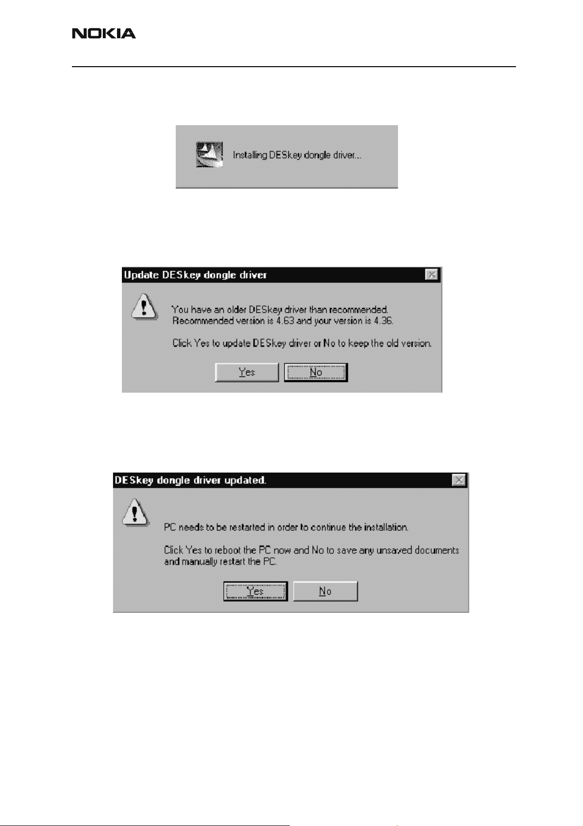
If there is no previously installed Dongle driver, installation will take place….
Figure 2: Dongle driver installation window
If the Dongle driver is installed and it is older than the latest supported version, the latest
version will be installed when you choose “Yes”. The latest version is always included in
the latest Phoenix installation package.
Figure 3: Dongle driver update window
PC needs to be rebooted before installation can continue. Click “Yes” to reboot the PC
Setup is restarted automatically after reboot..
Figure 4: Dongle driver update completed window
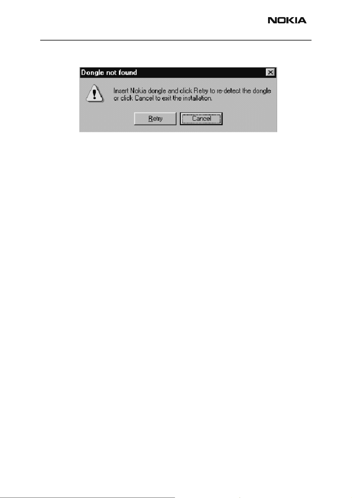
If at any point during installation you get this message, the Dongle is not found and
Issue 3 10/03 Copyright Nokia. All rights reserved. . Page 5
Page 6
TME-3 Company confidential
Service Software Instructio ns CCS Technical Documentation
installation can’t continue..
Figure 5: Error message at pre-installation
Possible reasons may be defective or too old PKD-1Dongle (five digit serial number Don-
gle when used whit FPS-8 Prommer) or that the FLS-4S POS Flash Dongle is defective or
power to it is not supplied by external charger.
Check the COM/parallel ports used first! After correcting the problem Installation can be
restarted
Page 6 Copyright Nokia. All rights reserved.. Issue 3 10/03
Page 7
Company confidential TME-3
CCS Technical Documentation Service Software Instructions
First time installation of Phoenix
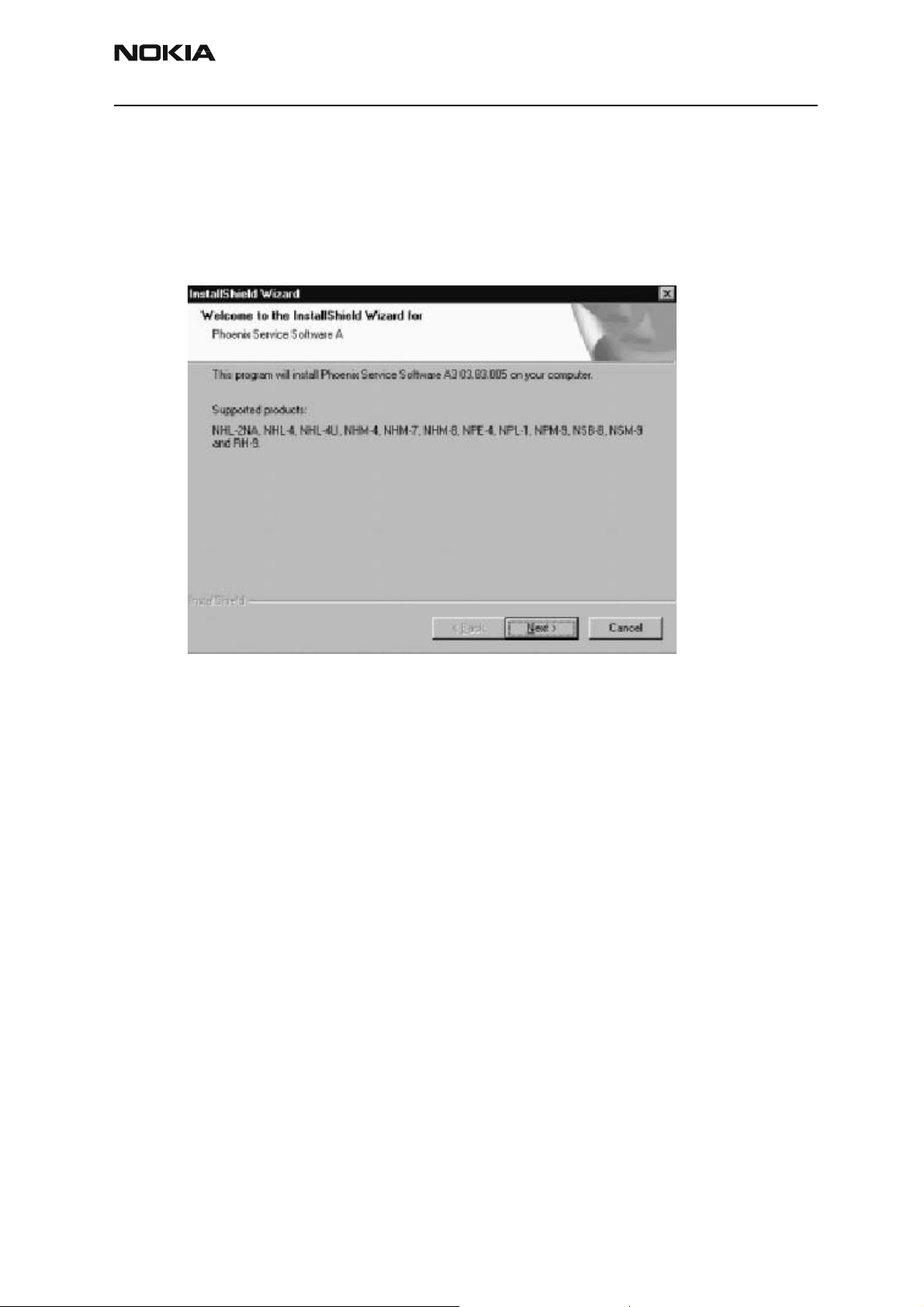
After Dongle driver installation / update (if needed) installation continues from this step.
If the Phoenix Service Software A is already installed proceed to p.11
Click “Next” in Welcome dialog to continue.
Figure 6: Welcome dialog
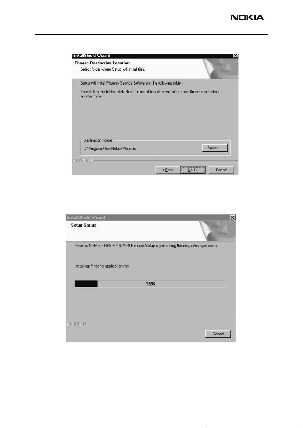
Choose the destination folder, it is recommended to use the default folder C:\Program
Files\Nokia\Phoenix.
Choose “Next” to continue. You may choose another location by selecting “Browse” (not
Issue 3 10/03 Copyright Nokia. All rights reserved. . Page 7
Page 8
TME-3 Company confidential
Service Software Instructio ns CCS Technical Documentation
recommended)
Figure 7: File location window
Setup copies the components, please wa it.
Progress of the setup is shown. Please wait…
Figure 8: Setup status window
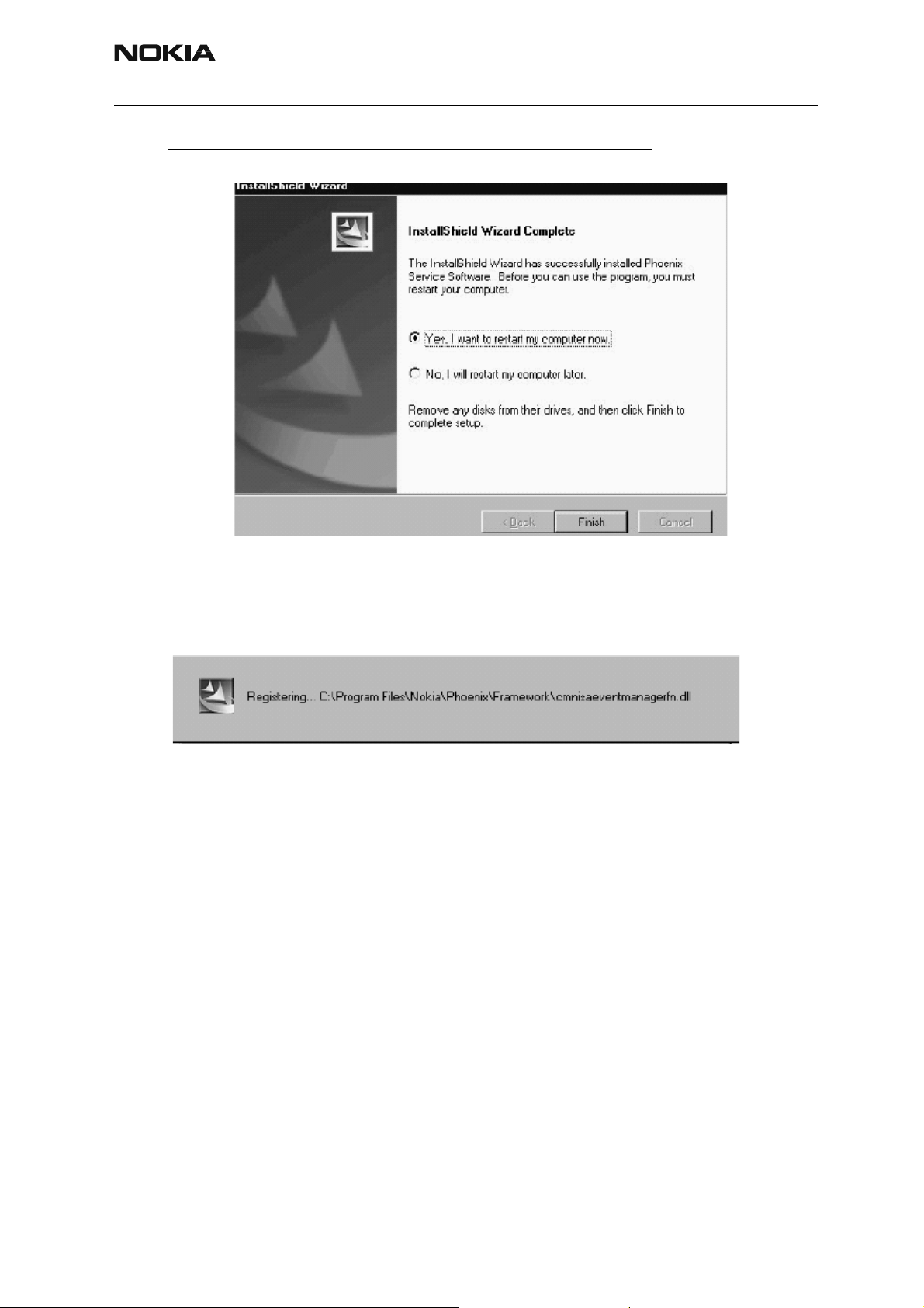
If restarting of your computer is needed the Install Shield Wizard will tell you about it.
Select “Yes…” to reboot the PC immediately and “No…” to reboot the PC manually.
Page 8 Copyright Nokia. All rights reserved.. Issue 3 10/03
Page 9
Company confidential TME-3
CCS Technical Documentation Service Software Instructions
Note that Phoenix doesn’t work, if components are not registered. Click “Finish” to con-
tinue. .
Figure 9: Installation complete -window
After the reboot components are registered and Phoenix is ready for use.
If reboot is not needed components are registered after copying them.
Figure 10: Registering window
Phoenix is now ready for use.
Now the installation of Phoenix Service SW is ready and it can be used for TME-3 after:
• Installing TME-3 specific Phoenix Service SW as follow the instructions “First
Time Installation Of Phoenix”
• Installing Phone model specific Phone Data Package for Phoenix
• Configuring the connections
• Updating the Flash Update Package files used with FPS-8* tool
Issue 3 10/03 Copyright Nokia. All rights reserved. . Page 9
Page 10

TME-3 Company confidential
Service Software Instructio ns CCS Technical Documentation
TME-3 Service Software Installation procedure
• Check that a Dongle is attached to the parallel port of your computer.
• Download the latest installation package (e.g.
phoenix_service_sw_a3_03_83_005.exe) to your comp uter (e.g.:\TEMP)
• Close all other programs
• Install Phoenix by executing the Phoenix installation package and follow the
instructions on the screen.
• Download the latest release (e.g. TME-3_03_83_010.exe). Please contact
your regional After Market Service point for information on where to download
the latest release.
• Run the application file (e.g. TME-3_03_83_010.exe) and follow instructions
on the screen
• Administrator rights may be required to be able to install Phoenix depending
on the Operating System
• If the dongle driver is installed or updated, you need to reboot your PC before
the installation can continue.
• If uninstalling or rebooting is needed at any point, you will be prompted by the
install Shield program.
Page 10 Copyright Nokia. All rights reserved.. Issue 3 10/03
Page 11
Company confidential TME-3
CCS Technical Documentation Service Software Instructions
Startup
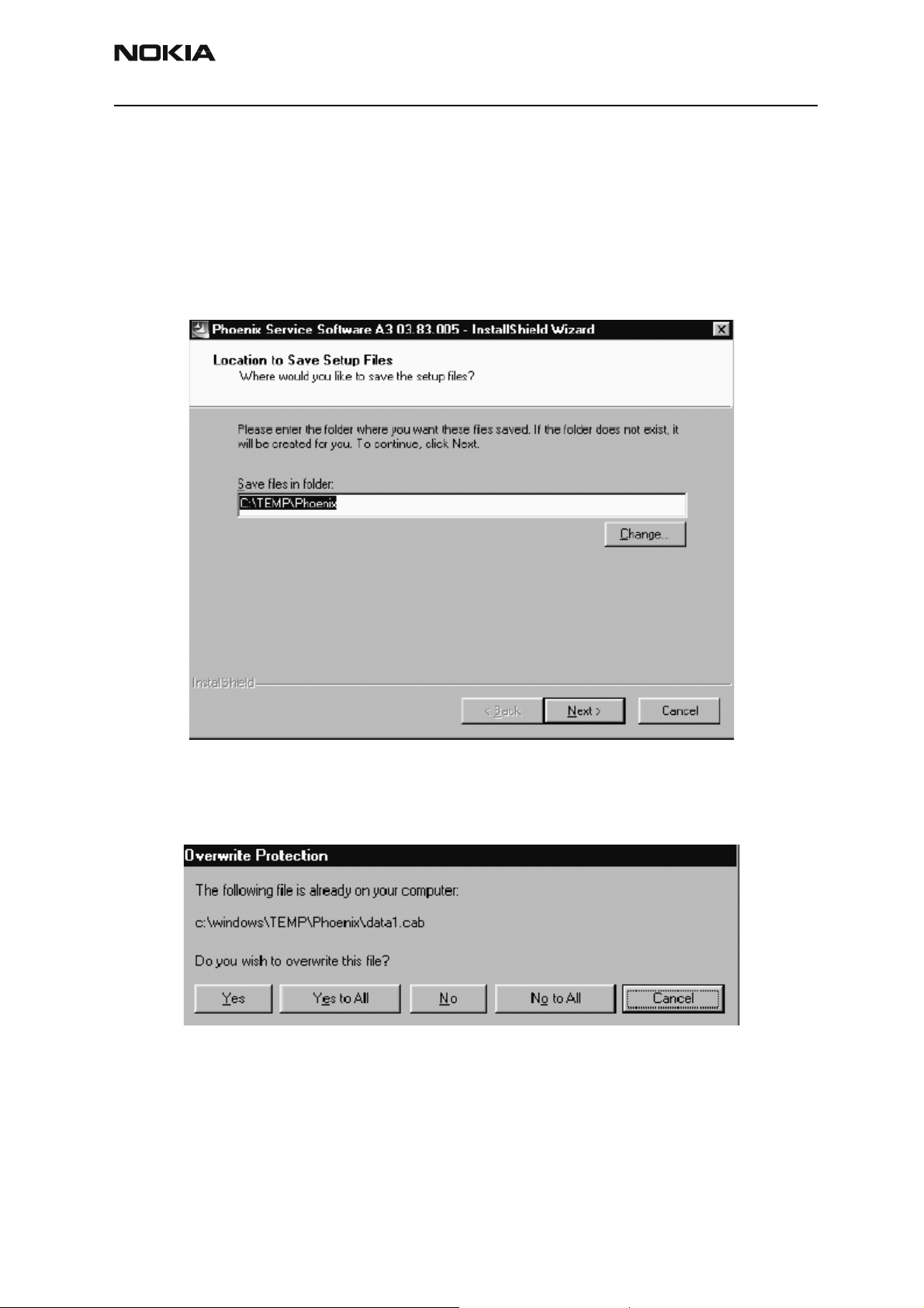
Run the phoenix_service_sw_a3_03_83_005.exe to start installation.
When you choose “Next” the files needed for installation will be extracted.
Kindly wait.
Figure 11:
If the setup files are already extracted (left in the file system from previous installati on)
following dialog appears. Always click “Yes to All” to overwrite the existing setu p files
Figure 12: Overwrite protection
Issue 3 10/03 Copyright Nokia. All rights reserved. . Page 11
Page 12
TME-3 Company confidential
Service Software Instructio ns CCS Technical Documentation
Update Installation of Phoenix
If you already have the Phoenix Service SW installed on your computer, sooner or later
there will be need to update it when new versions are released.
Please note that very often the Phoenix Service SW and the Phone Specific Data Package
for Phoenix come in pairs, meaning that certain version of Phoenix can only be used with
certain version of Data Package. Always use the latest available versions of both. Instructions can be found in phone model specific Technical Bulletins.
To update the Phoenix you need to take exactly the same steps as when installing it for
the first time.
• Download the installati on package to your computer hard disk
• Close all other programs
• Run the application file (
• Dongle driver version will be checked and if need be, updated
• After reboot installation starts automatically
• Newer version of Phoenix will be inst alled
phoenix_service_sw_a3_03_83-005.exe)
When you update the Phoenix from old to new version (e.g. update from 3.83.005 to
3.83.0055), the update will take place automatically without uninstallation
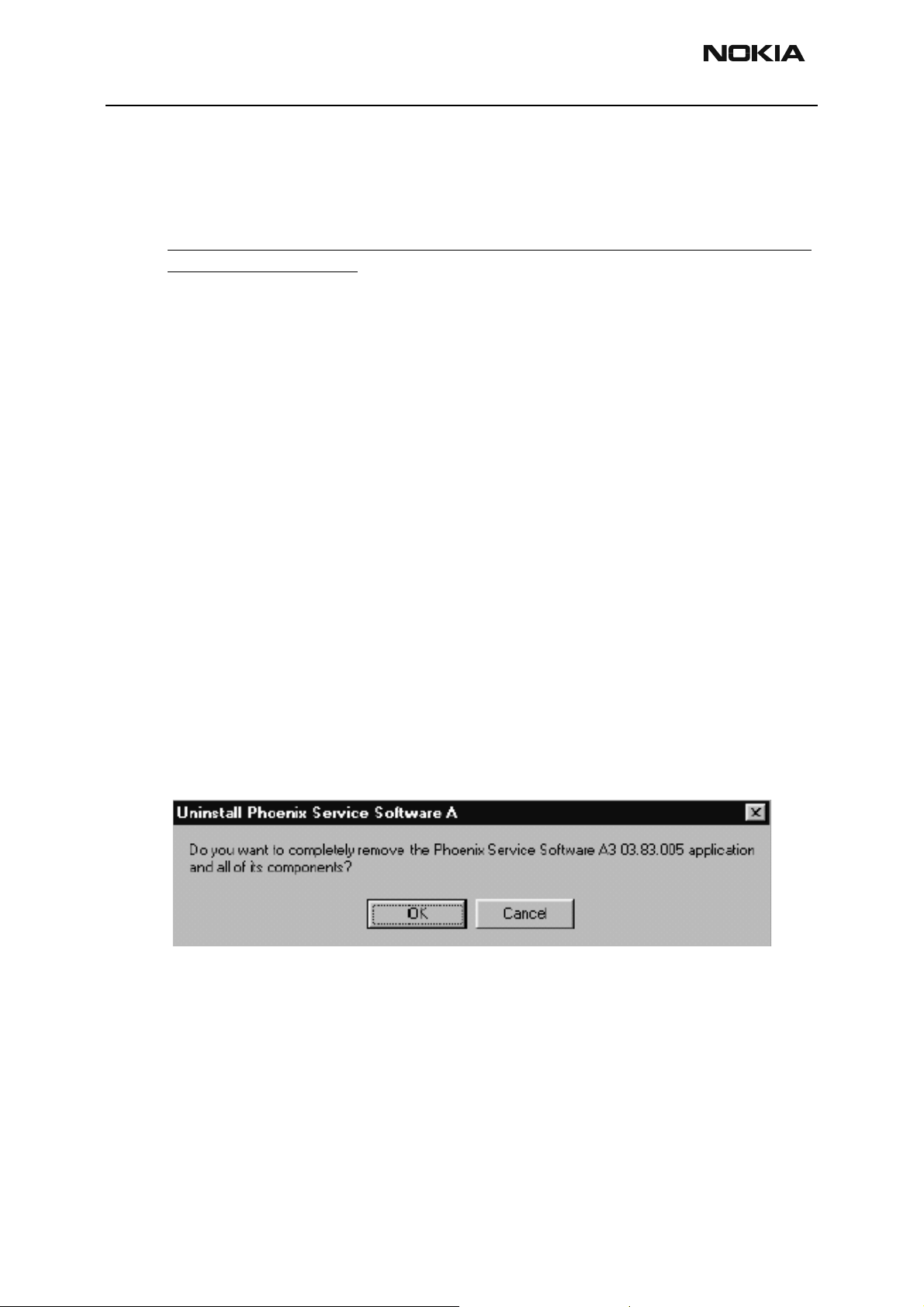
If you try update the Phoenix with the same version that you already have (e.g. 3.55 to
3.55) you are asked if you want to uninstall the version of Phoenix you have on your PC.
Answer “OK” to uninstall Phoenix, “Cancel” if you don’t want to uninstall..
Figure 13: Unistallation window
If you try to install an older version (e.g. downgrade from 3.83.005 to 3.83.000) installation will be interrupted.
Always follow the instructions on the screen.
Page 12 Copyright Nokia. All rights reserved.. Issue 3 10/03
Page 13
Company confidential TME-3
CCS Technical Documentation Service Software Instructions
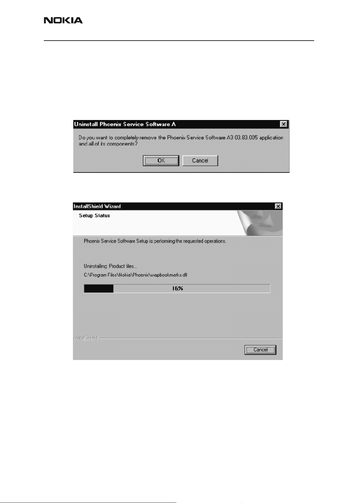
How to uninstall Phoenix
Uninstallation can be done manually from Windows Control Panel – Add/Remove Programs.
Choose “Phoenix Service Software” and click “Add/Remove”.
Choose “OK” to uninstall.
Figure 14: Uninstallation window
Progress of the uninstallation is shown.
Figure 15: Setup status window
Issue 3 10/03 Copyright Nokia. All rights reserved.. Page 13
Page 14
TME-3 Company confidential
Service Software Instructio ns CCS Technical Documentation
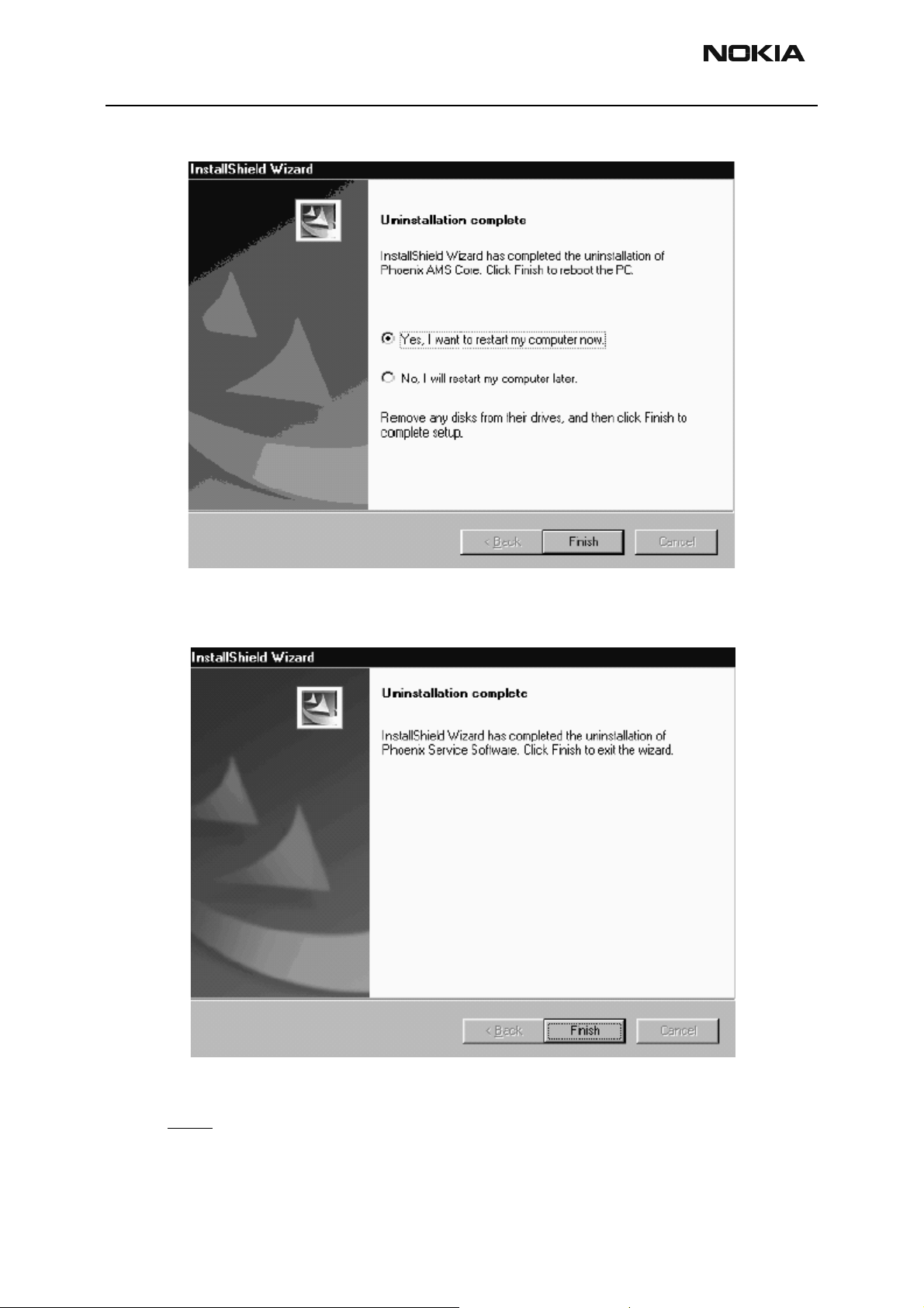
You may have to reboot the PC after uninstallation.
Figure 16:
If restarting is not needed, the following dialog will appear:
Figure 17:
Note! If you have different product packages installed, components are uninstalled only
if they are not included in other product packages.
Page 14 Copyright Nokia. All rights reserved.. Issue 3 10/03
Page 15

Company confidential TME-3
CCS Technical Documentation Service Software Instructions
Data package for Phoenix (product specific)
Note! the following pages show the NHL-4 Data Package Installation/ uninstallation, the
procedure is similar with TME-3.
Before installation
Product Data Package contains all product specific data to make the Phoenix Service
Software and tools usable with a certain phone model.
It also includes the latest version of flash update package for FLS-4* and FPS-8*
• Check that the Dongle is attached to the parallel port of your computer.
• Install Phoenix Service SW
• Download the install ation package (e.g. nhl-4_dp_1.00.exe) to your computer
(e.g. C:\TEMP)
• Close all other programs
• Run the application file (e. g.nhl-4_dp_1.00.exe) and follow i nstructio ns on the
screen
If you already have the Phoenix Service SW installed on your computer, sooner or later
there will be need to update it when new versions are released.
Please note that very often the Phoenix Service SW and the Phone Specific Data Package
for Phoenix come in pairs, meaning that certain version of Phoenix can only be used with
certain version of Data Package. Always use the latest available versions of both. Instructions can be found in phone model specific Technical Bulletins.
Issue 3 10/03 Copyright Nokia. All rights reserved.. Page 15
Page 16

TME-3 Company confidential
Service Software Instructio ns CCS Technical Documentation
Installa tion of Phoenix Data Package (Product Specific)
Run the
When you choose “Next” the files needed for installation will be extracted. Please wait…
nhl-4_dp_v_1.00.exe
to start installation.
Choose “Next” to continue.
From this view you can see the contents of the Data Package.
Read the text carefully.
Page 16 Copyright Nokia. All rights reserved.. Issue 3 10/03
Page 17

Company confidential TME-3
CCS Technical Documentation Service Software Instructions
There should be information about the Phoenix version nee d ed with this data package.
Choose “Next”.
Confirm location and choose “Next” to continue.
Install Shield checks where the Phoenix applicati on i s installed and the directory is
shown. Choose “Next” to continue.
Phone model specific files will be installed... kindly wait.
Issue 3 10/03 Copyright Nokia. All rights reserved.. Page 17
Page 18

TME-3 Company confidential
Service Software Instructio ns CCS Technical Documentation
Choose “Finish” to complete installation.
You now have all phone model specific files installed in your Phoenix Service SW.
Page 18 Copyright Nokia. All rights reserved.. Issue 3 10/03
Page 19

Company confidential TME-3
CCS Technical Documentation Service Software Instructions
How to Uninstall Data Package
Uninstallation can also be done manually from Windows Control Panel / Add / Remove
Programs/
If you try to install the same version of Phoenix Data Package that you already have, you
are asked if you want to uninstall the version you have on your PC. Answer “OK” to uninstall, “Cancel” if you don’t want to uninstall. Older versions of data packages do not need
to be uninstalled.
“NHL-4 Phone Data Package”.
Once the previously installed Data package is uninstalled, choose “Finish”.
Run the
Issue 3 10/03 Copyright Nokia. All rights reserved.. Page 19
nhl-4_dp_v_1.00.exe
again to continue installation from the beginning.
Page 20

TME-3 Company confidential
Service Software Instructio ns CCS Technical Documentation
How to Manage Connections
Start Phoenix Service SW and Login.
Figure 18: Phoenix icon
Choose “Manage Connections” From “File” – Menu
Figure 19: File menu
Existing connections can be selected, edited, deleted and new ones created by using this
dialog.
A connection can be created either manually or by using a Connection Wizard.
To add new connection, choose “Add” and select if you want to create it manually or by
using the Wizard.
Figure 20: Manage connections window
Page 20 Copyright Nokia. All rights reserved.. Issue 3 10/03
Page 21

Company confidential TME-3
CCS Technical Documentation Service Software Instructions
Choose “Next” to continue.
In the next dialogs you will be asked to select some settings for the connection
Figure 21: Connection settings window
Manual Settings
A) For FLS-4S POS Flash Device choose following connection settings
Media: FBUS
B) For FPS-8 Flash Prommer choose following connection settings:
Media: FPS-8
Port Num: COM Port where FPS-8 is connected
COMBOX_DEF_MEDIA: FBUS
Choose “Finish” to complete.
If you use the Wizard, connect the tools and a phone to your PC and the wizard will
automatically try to configure the correct connection.
Issue 3 10/03 Copyright Nokia. All rights reserved. . Page 21
Page 22

TME-3 Company confidential
Service Software Instructio ns CCS Technical Documentation
Activate the connection you want to use by clicking it and use up/down arrows to move
it on top of the list. Choose “Apply”.
The connection is now selected and can be used after closing the “Manage Connections”
window.
Figure 22: Managing connections window
Selected connection will be shown on the right hand bottom corner of the screen.
Figure 23: Sselected connection window
To use the selected connection, connect the phone to Phoenix with correct service tools,
make sure that it is switched on and select “Scan Product”.
Figure 24: Scan product window
When the Product is found, Phoenix will load product support and when everything is
ready, name of the loaded product support module and its version will be shown on the
bottom of the screen.
Figure 25: Support module and ID window
Page 22 Copyright Nokia. All rights reserved.. Issue 3 10/03
Page 23

Company confidential TME-3
CCS Technical Documentation Service Software Instructions
How to Update Flash Support Files for FPS-8* and FLS-4*
Before Installation
• Install Phoenix Service SW and Phoenix data package.
• Install the phone model Specific Datapackage for Phoenix
• The flash support files are delivered in the same installation package with
Phoenix data package.
• Normally it is enough to i nst al l the dat a p ac kage onl y befor e upda ting t he FPS-
8.
• Separate instal lation package is for flash support files are available, and the
files can be updated according to this instruction.
Installing the Flash Support Files
Start by double clicking eg. flash_update_02_10_00.exe. Installation begins.
Figure 26: Installation window
If you already have the same Flash Update package files installed, you need to confirm if
you want them to be reinstalled.
Figure 27: Uninstallation window
Issue 3 10/03 Copyright Nokia. All rights reserved.. Page 23
Page 24

TME-3 Company confidential
Service Software Instructio ns CCS Technical Documentation
Choose “Next” to continue installation
Figure 28: Welcome window
It is highly recommended to install the files to the default destination folder
Files\Nokia\Phoenix
.
C:\Program
Choose “Next” to continue. You may choose another location by selecting “Browse” (not
recommended).
Figure 29: File location window
Page 24 Copyright Nokia. All rights reserved.. Issue 3 10/03
Page 25

Company confidential TME-3
CCS Technical Documentation Service Software Instructions
Installation continues…
Figure 30: Setup status window
Choose “Finish” to complete procedure.
• FPS-8* must be updated by using Phoenix!
Figure 31: Maintenance complete window
Issue 3 10/03 Copyright Nokia. All rights reserved.. Page 25
Page 26

TME-3 Company confidential
Service Software Instructio ns CCS Technical Documentation
How to Update The FPS-8* Flash Prommer SW
Start Phoenix Service Software
Select”FPS-8 / FPS-8C maintenance” from”Flashing” menu.
Figure 32: Flashing menu
When new FPS-8 flash update package is installed to computer you will be asked to
update the files to your FPS-8 Prommer. Select”Yes” to update files..
0200
Figure 33: Update selection window
Update procedure takes a couple of minutes.
Figure 34: Update in process window
Page 26 Copyright Nokia. All rights reserved.. Issue 3 10/03
Page 27

Company confidential TME-3
CCS Technical Documentation Service Software Instructions
Figure 35: Maintenance window
FPS-8 sw can also be updated by pressing”Update” button and selecting appropriate
fps8upd.ini file under
C:\Program Files\Nokia\Phoenix
Figure 36: Update file window
\Flash - directory.
All files can be loaded separately to FPS-8. To do this, just press right mouse button in
Flash box files” window and select file type to be loaded. More information and help can
be found from the “Help” dialog.
Issue 3 10/03 Copyright Nokia. All rights reserved.. Page 27
Page 28

TME-3 Company confidential
Service Software Instructio ns CCS Technical Documentation
FPS-8 Activation and Deactivation
• Before the FPS-8 can be successfully used for phone programming, it must be
first activate d.
• If there is a need to send FPS- 8 box to somewhere e. g. for rep air, box must be
first deactivated.
Activation
Before FPS-8 can be successfully used for phone programming, it must be first activated.
Fill in first “FPS-8 activation request” sheet, in the FPS-8 sales package and follow the
instructions in the sh e et .
When activation file is received (e.g. 00000.in), copy it to C:\Program-
Files\Nokia\Phoenix\BoxActivation - Directory on your computer
created when Phoenix is installed).
(This directory is
Start Phoenix Service Software .
Select ”FPS-8 / FPS-8C maintenance” from ”Flashing” menu.
Figure 37: Flashing menu
Select “Activate” from the “FPS8/8C Maintenance” – UI.
Figure 38: FPS-8/8C maintenance window
Page 28 Copyright Nokia. All rights reserved.. Issue 3 10/03
Page 29

Company confidential TME-3
CCS Technical Documentation Service Software Instructions
The activation file you saved to C:\ProgramFiles\Nokia\Phoenix\BoxActivation - directory
will be shown (e.g. 00000.in), check that it is correct.
Box will be activated when you choose “Open”
Turn FPS-8 power off and on to complete activation
Deactivation
Start Phoenix Service Software .
Select ”FPS-8 / FPS-8C maintenance” from ”Flashing” menu
Select “Deactivate” from the “FPS8/8C Maintenance” – UI.
Confirm Deactivation by choosing “Yes”, Box will be deactivated.
Figure 39: Box activation window
Figure 40: Box deactivation window
Turn FPS-8 power off and on to complete deactivation
Issue 3 10/03 Copyright Nokia. All rights reserved.. Page 29
Page 30

TME-3 Company confidential
Service Software Instructio ns CCS Technical Documentation
JBV-1 Docking Station SW
The JBV-1 Docking Station is a common tool for all DCT-4 generation products. In order
to make the JBV-1 usable with different phone models, a phone specific Docking Station
Adapter is used for different service functions.
The JBV-1 Docking Station contains Software (Firmware) which can be updated.
You need the following equipment to be able to update JBV-1 software:
• PC with USB connection
• Operating System supporting USB (Not Win 95 or NT)
• USB Cable (Can be purchased from shops or suppliers providing PC hardware and accessories)
• JBV-1 Docking Station
• External Power Supply 11-16V
Before Installation
• Download Jbv1_update.zip – file to your computer (e.g. C:\TEMP) from your
download web site.
• Close all other programs
• Follow instructions on the screen
Page 30 Copyright Nokia. All rights reserved.. Issue 3 10/03
Page 31

Company confidential TME-3
CCS Technical Documentation Service Software Instructions
Installing SW Needed for the JBV-1 SW Update
Note: DO NOT CONNECT THE USB CABLE / JBV-1 TO YOUR COMPUTER YET!
Run
Jbv1_update.zip
Files needed for JBV-1 Package setup Program will be extracted.
file and start SW Installation by double clicking
Setup.exe
.
Figure 41: JBV-1 update installation window
Installation begins, please read the information shown and Choose “Next” to continue.
Figure 42: Welcome window
Use suggested destination folder where JBV-1 SW Package will be installed and choose
Issue 3 10/03 Copyright Nokia. All rights reserved. . Page 31
Page 32

TME-3 Company confidential
Service Software Instructio ns CCS Technical Documentation
“Next” to continue.
Figure 43: Select location window
Select “Full” Installation and choose “Next” to continue
Figure 44: Select components window
Program Folder will be created. Choose “Next” to continue, Software files will be
Page 32 Copyright Nokia. All rights reserved.. Issue 3 10/03
Page 33

Company confidential TME-3
CCS Technical Documentation Service Software Instructions
installed.
Figure 45: Select folder window
After successful installation, choose “Finish” to complete.
Figure 46: Setup complete window
NOW YOU CAN CONNECT THE USB CABLE / JBV-1 TO YOUR COM-
Issue 3 10/03 Copyright Nokia. All rights reserved.. Page 33
Page 34

TME-3 Company confidential
Service Software Instructio ns CCS Technical Documentation
PUTER!
Connect power to JBV-1 (11-16V DC) from external power supply, then connect USB
Cable between JBV-1 USB connector and PC.
Windows will detect connected USB cable and detect drivers for new HW.
Follow the instructions and allow Windows to search and install the best drivers avail-
able. After this procedure the actual JBV-1 SW update can begin.
Figure 47: Add new hardware window
Page 34 Copyright Nokia. All rights reserved.. Issue 3 10/03
Page 35

Company confidential TME-3
CCS Technical Documentation Service Software Instructions
Updating the JBV-1 Docking Station Software
Go to folder C:\Program Files\Nokia\ JBV-1 SW Package\ FIRMWARE UPDATE and start
JBV-1 Update SW by double clicking fwup.exe.
JBV-1 Firmware update starts and shows current status of the JBV-1 connected.
If firmware version read from your JBV-1 is not the latest one available, it needs to be
updated by choosing “Update Firmware”.
Figure 48: JBV-1 update window
Choose file JBV1v11.CDE (example used here is for v 11) and “Open” to update your JBV-
1.
Figure 49: Firmware file selection
After Successful update, current JBV-1 status will be shown. You have now updated the
software of your JBV-1 docking station and it is ready for use.
Issue 3 10/03 Copyright Nokia. All rights reserved.. Page 35
Page 36

TME-3 Company confidential
Service Software Instructio ns CCS Technical Documentation
Figure 50: Update completed window
Page 36 Copyright Nokia. All rights reserved.. Issue 3 10/03
Page 37

Company confidential TME-3
CCS Technical Documentation Service Software Instructions
TME-3 specific menus in Phoenix
TME-3 specific menus in Phoenix are listed below
Figure 51: TME-3 Specific menus
Service Box (SB-1) for testing of M2M system connector uses following menus:
• M2M System Connector
• Remote I/O Control & Audio settings
Note: the three menu items at the bottom of the window are not in use !
Issue 3 10/03 Copyright Nokia. All rights reserved.. Page 37
Page 38

TME-3 Company confidential
Service Software Instructio ns CCS Technical Documentation
Light Indicators
Main functionality
• Led groups (Led 1, Led 2, Led 3) data can be read from product by pres sing
"Read" button on the group
• Led groups (Led 1, Led 2, Led 3) data can be write to product by pressing
"Write" button on the gro up
• All Led data can be headed to product at once by pressing "Read All" button
on Common group
• All Led data can be written from product at once by pressing "Write All" button
on Common group
• "Help" button open Help file
The following screenshot shows the visual part of Light Indicators.
Figure 52: Light indicators window
Page 38 Copyright Nokia. All rights reserved.. Issue 3 10/03
Page 39

Company confidential TME-3
CCS Technical Documentation Service Software Instructions
M2M System Connector
Main functionality
• Parameters group data can be read by pressing "Read" button
• Parameters group data can be write by pressing "Write" button
• Counters group data can be read by pressing "Read" button
• Counters can be resetted by pressing "Reset " button.
• "Automatic reading time" edit box identifies automatic counters reading time.
• All data on the control can be read by pressing "Read All" button
• All data on the control can be write by pressing "Write All" button
• Default values can be set to all controls by pressing "Set Defaults" button
• "Help" button open Help file
The following screenshot shows the visual part of M2M System Connector.
Figure 53: M2M connector
Issue 3 10/03 Copyright Nokia. All rights reserved.. Page 39
Page 40

TME-3 Company confidential
Service Software Instructio ns CCS Technical Documentation
Remote I/O Control & Audio settings
Main functionality
• Aif interface output control group data can be read from product by pressing
"Read" button on the group
• Aif interface input control group data can be read from product by pressing
"Read" button on the group
• "Help" button open Help file
The following screenshot shows the visual part of Remote I/O control & Audio settings.
Figure 54: Remote I/O control & Audio settings
Page 40 Copyright Nokia. All rights reserved.. Issue 3 10/03
Page 41

Company confidential TME-3
CCS Technical Documentation Service Software Instructions
Hardware setup instructions
Flash Concept
7
9
8
6
4
3
2
1
Figure 55: Flash concept
5
Flash Concept list
Item Service Accessory Type Product code:
1. Flashing ada p t e r FLA-34 0770375
2. Power cable PCS-1 0730012
3. Serial cable XCS-4 0730178
4. Flash prommer box FPS–8 0080321
5. Printer cable incl. in FPS–8 sales pack 0730029
6. D9 – D9 cable, AXS–4 incl. in FPS–8 sales pack 0730090
7. Software protection key PKD–1 0750018
8. CD–ROM Phoenix Service SW Downloadable from PWS
CD–ROM TME-3 Flash SW data Downloadable from PWS
9. Power supply ACF-8 incl. in FPS–8 sales pack 0680032
DCT3 power supply module ACS-10 0770340
Issue 3 10/03 Copyright Nokia. All rights reserved. . Page 41
Page 42

TME-3 Company confidential
Service Software Instructio ns CCS Technical Documentation
Point of sale (POS) flashing concept
4
5
6
3
2
1
Figure 56: POS (Point Of Sale) flashing concept
Item Service Accessory Type Product Code:
1. Flashing Adapter FLA-34 0770375
2. Powe r cable PCS-1 0730012
3. Serial cable XCS-4 0730178
4. Americas sales package FLS-4S 0080543
E&A sales package FLS-4S 0080541
APAC sales package FLS-4S 0080542
5. CD-ROM TME-3 Flash Sw Data Downloadable from PWS
CD-ROM Phoenix Service SW Downloadable from PWS
6 Power supply ACF-8 0680032
Page 42 Copyright Nokia. All rights reserved.. Issue 3 10/03
Page 43

Company confidential TME-3
CCS Technical Documentation Service Software Instructions
Jig Concept
The jig concept can be used for RF tuning and testing.
5
6
4
2
3
Figure 57: Jig concept
1
Jig concept list
Item Service accessory: Type Product code:
1. Module Jig MJS-63 0770377
2. Power cable (for external power supply) PCS-1 0 73 0012
3. Service cable XRC-5 0730276
4. Cable DAU-9S 0730108
5. Software protection key PKD–1 075001 8
6.
CD-ROM TME-3 Flash Sw Data 0775321
CD-ROM Phoenix Service SW 0774280
Issue 3 10/03 Copyright Nokia. All rights reserved.. Page 43
Page 44

TME-3 Company confidential
Service Software Instructio ns CCS Technical Documentation
JBV-1 Flash Concept
JBV-1 concept can be used for RF tuning and testing.
6.
8.
7.
5.
4.
1.
3.
2.
Figure 58: JBV-1 Flash concept
Item: Service accessory: Type Product code:
1 Docking station JBV–1 0770298
Docking station adapter MJF–21 0770374
2 Power cable PCS-1 0730012
3 Modular cable XCS–4 0730178
4 Flash prommer box FPS–8 0080321
5 Printer cable, incl. in FPS–8 sales pack Printer cable, 0730029
6 D9 – D9 cable,
incl. in FPS–8 sales pack
7 Software protection key PKD–1 0750018
8. Power supply incl. in FPS–8 sales pack ACF-8 0680032
CD-ROM TME-3 Flash Sw Data 0775321
CD-ROM Phoenix Service SW 0774280
AXS–4 0730090
Page 44 Copyright Nokia. All rights reserved.. Issue 3 10/03
Page 45

Company confidential TME-3
CCS Technical Documentation Service Software Instructions
JBV-1 Service Concept
JBV-1 jig concept can be used for RF tuning and testing
Figure 59: JBV-1 Service Concept
JBV-1 concept list
Item: Service accessory: Type: Product code:
1. Docking station JB V–1 0770298
2. Docking stat i o n adapter MJF–21 0770374
3. Power cable PCS-1 (for external power supply) 0730012
4. Service cable XRC-5 0730276
5. Cable DAU-9S 0730108
6. Software protection key PKD–1 0750018
7. CD–ROM Phoenix Service SW 0774280
CD–ROM TME-3 Flash SW data 0775321
Issue 3 10/03 Copyright Nokia. All rights reserved.. Page 45
Page 46

TME-3 Company confidential
Service Software Instructio ns CCS Technical Documentation
Service Box SB-1 set-up
Figure 60: SB-1 set-up
SB-1 concept list
Item: Service accessory: Type: Product code:
1.
2.
3. D9-D9 cable AXS-4 0730090
4.
5.
Service box SB-1 0770559
Pow er ca ble PCS-1 0730012
Software protection key PKD-1 0750018
CD-ROM Phoenix service SW 0774280
Page 46 Copyright Nokia. All rights reserved.. Issue 3 10/03
Page 47

Company confidential TME-3
CCS Technical Documentation Service Software Instructions
[This page left intentionally blank]
Issue 3 10/03 Copyright Nokia. All rights reserved.. Page 47
Page 48

TME-3 Company confidential
Service Software Instructio ns CCS Technical Documentation
Page 48 Copyright Nokia. All rights reserved.. Issue 3 10/03
 Loading...