

Page 1

ENGINE
A
ACC
SECTION ACC
ACCELERATOR CONTROL SYSTEM
CONTENTS
PRECAUTION ............................................... 2
PRECAUTIONS ................................................... 2
Precaution for Supplemental Restraint System
(SRS) "AIR BAG" and "SEAT BELT PRE-TEN-
SIONER" ...................................................................
REMOVAL AND INSTALLATION ................ 3
ACCELERATOR CONTROL SYSTEM ............... 3
Component ............................................................... 3
Removal and Installation .......................................... 3
SERVICE DATA AND SPECIFICATIONS
(SDS) ............................................................. 5
2
SERVICE DATA AND SPECIFICATIONS
(SDS) ..................................................................
Accelerator Control ................................................... 5
C
D
E
F
G
H
5
I
J
K
M
N
O
P
L
ACC-1
Page 2

PRECAUTIONS
< PRECAUTION >
PRECAUTION
PRECAUTIONS
Precaution for Supplemental Restraint System (SRS) "AIR BAG" and "SEAT BELT
PRE-TENSIONER" INFOID:0000000004064152
The Supplemental Restraint System such as “AIR BAG” and “SEAT BELT PRE-TENSIONER”, used along
with a front seat belt, helps to reduce the risk or severity of injury to the driver and front passenger for certain
types of collision. This system includes seat belt switch inputs and dual stage front air bag modules. The SRS
system uses the seat belt switches to determine the front air bag deployment, and may only deploy one front
air bag, depending on the severity of a collision and whether the front occupants are belted or unbelted.
Information necessary to service the system safely is included in the SR and SB section of this Service Manual.
WARNING:
•To avoid rendering the SRS inoperative, which could increase the risk of personal injury or death in
the event of a collision which would result in air bag inflation, all maintenance must be performed by
an authorized NISSAN/INFINITI dealer.
•Improper maintenance, including incorrect removal and installation of the SRS, can lead to personal
injury caused by unintentional activation of the system. For removal of Spiral Cable and Air Bag
Module, see the SR section.
•Do not use electrical test equipment on any circuit related to the SRS unless instructed to in this
Service Manual. SRS wiring harnesses can be identified by yellow and/or orange harnesses or harness connectors.
ACC-2
Page 3
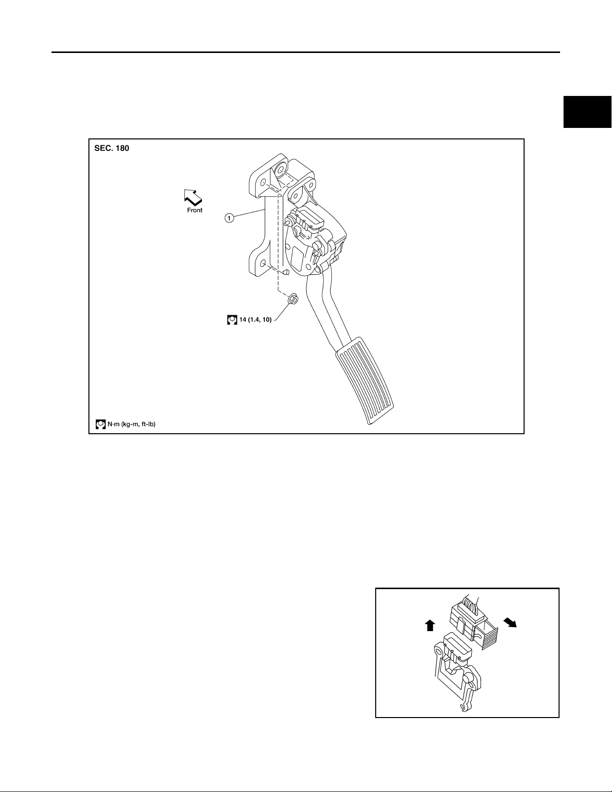
ACCELERATOR CONTROL SYSTEM
< REMOVAL AND INSTALLATION >
REMOVAL AND INSTALLATION
ACCELERATOR CONTROL SYSTEM
Component INFOID:0000000004064153
A
ACC
C
D
E
F
G
H
VAH@/483D
1. Non-adjustable accelerator pedal assembly
CAUTION:
•Do not disassemble the accelerator pedal assembly.
•Do not remove the accelerator pedal position sensor from the accelerator pedal bracket.
•Avoid damage from dropping the accelerator pedal assembly during handling.
•Keep the accelerator pedal assembly away from water.
Removal and Installation INFOID:0000000004064154
REMOVAL
1. Disconnect the negative battery terminal.
2. Disconnect the accelerator position sensor electrical connector.
a. Pull the connector lock back to unlock the connector from the
accelerator pedal position sensor as shown.
b. Pull up on the connector to disconnect it from the accelerator
pedal position sensor as shown.
3. Remove the two upper and one lower accelerator pedal nuts.
4. Remove the accelerator pedal assembly.
CAUTION:
•Do not disassemble the accelerator pedal assembly.
•Do not remove the accelerator pedal position sensor from
the accelerator pedal bracket.
•Avoid damage from dropping the accelerator pedal assembly during handling.
•Keep the accelerator pedal assembly away from water.
KAH @/222D
I
J
K
L
M
N
O
P
ACC-3
Page 4
ACCELERATOR CONTROL SYSTEM
< REMOVAL AND INSTALLATION >
INSTALLATION
Installation is in the reverse order of removal.
INSPECTION AFTER INSTALLATION
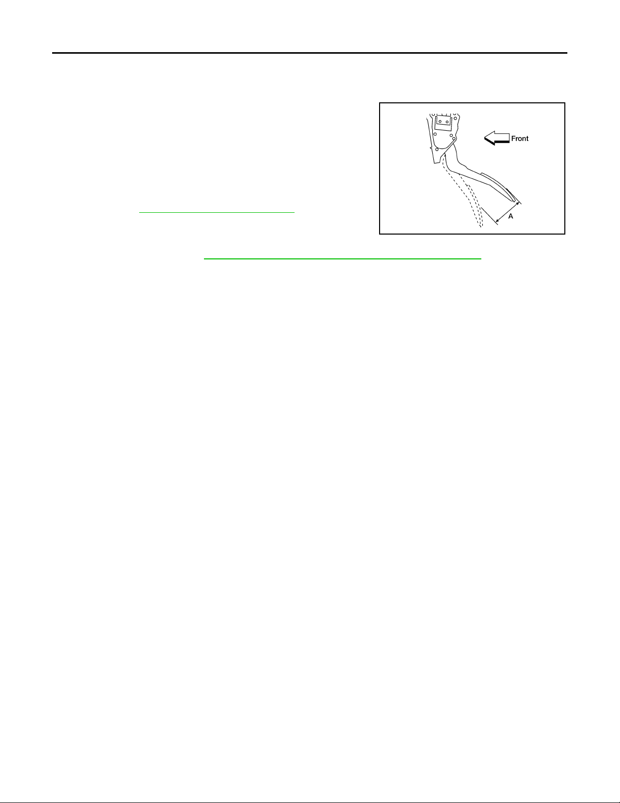
•Check that the accelerator pedal moves smoothly within the specified range.
Accelerator pedal - total pedal
applied stroke “A”
•Check that the accelerator pedal smoothly returns to the original
position.
•Perform an electrical inspection of the accelerator pedal position
sensor. Refer to EC-367, "
CAUTION:
When the harness connector of the accelerator pedal position
sensor is disconnected, perform ″Accelerator Pedal Released
Position Learning″. Refer to EC-19, "
Component Inspection".
: 48 mm (1.89 in)
Accelerator Pedal Released Position Learning".
KAH @/323D
ACC-4
Page 5
SERVICE DATA AND SPECIFICATIONS (SDS)
< SERVICE DATA AND SPECIFICATIONS (SDS)
SERVICE DATA AND SPECIFICATIONS (SDS)
SERVICE DATA AND SPECIFICATIONS (SDS)
Accelerator Control INFOID:0000000004064155
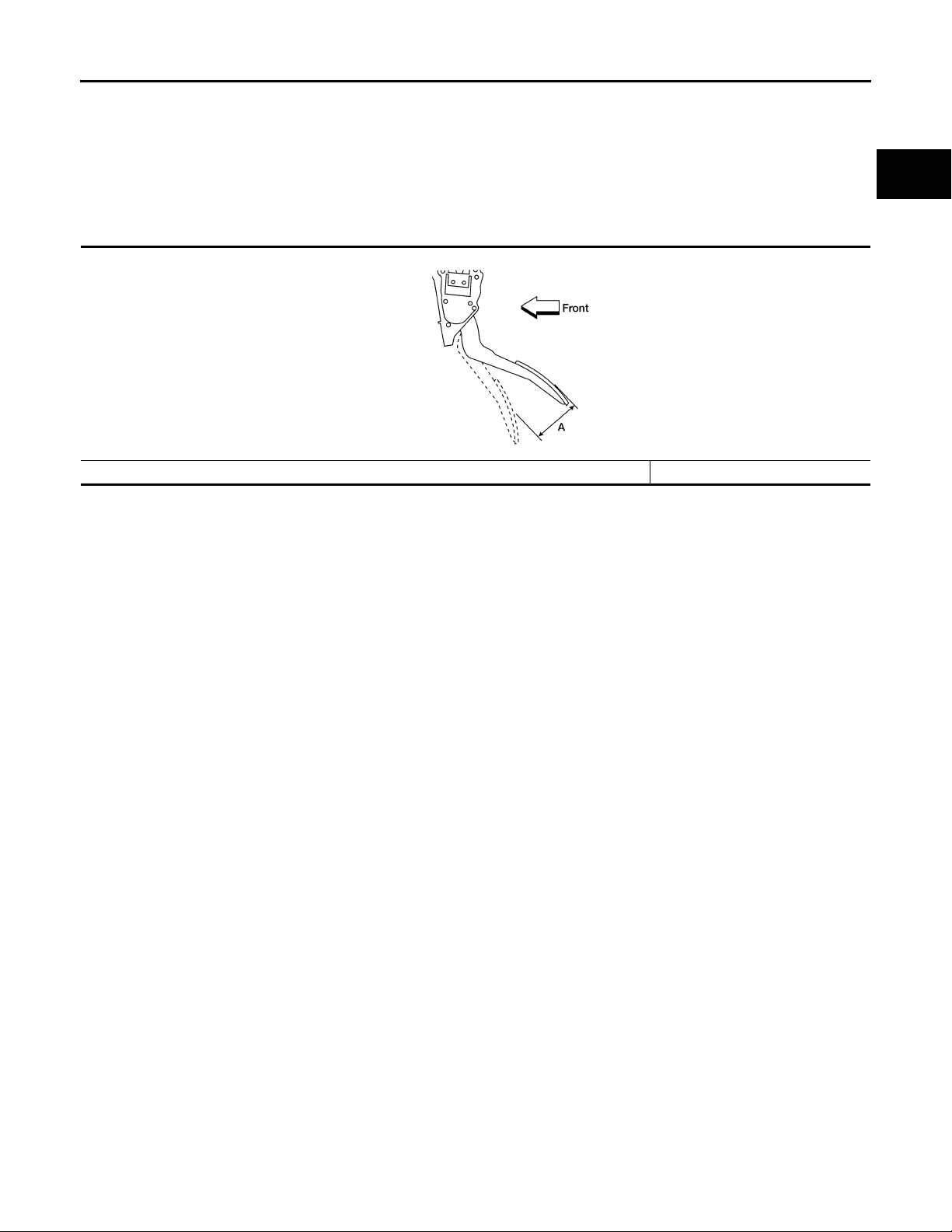
ACCELERATOR PEDAL
Unit: mm (in)
KAH @/323D
Accelerator pedal - total pedal applied stroke “A” 48 (1.89)
A
ACC
C
D
E
F
G
H
K
M
N
O
P
I
J
L
ACC-5
Page 6

DRIVER INFORMATION & MULTIMEDIA
A
B
SECTION AV
AUDIO, VISUAL & NAVIGATION SYSTEM
CONTENTS
BASE AUDIO
BASIC INSPECTION ....................................
DIAGNOSIS AND REPAIR WORKFLOW .......... 4
Work Flow .................................................................4
FUNCTION DIAGNOSIS ............................... 6
AUDIO SYSTEM .................................................. 6
System Diagram ........................................................6
System Description ...................................................6
Component Parts Location ........................................7
Component Description .............................................7
COMPONENT DIAGNOSIS .......................... 8
Symptom Table .......................................................23
NORMAL OPERATING CONDITION ...............24
4
Description ...............................................................24
PRECAUTION ..............................................25
PRECAUTIONS .................................................25
Precaution for Supplemental Restraint System
(SRS) "AIR BAG" and "SEAT BELT PRE-TEN-
SIONER" .................................................................
PREPARATION ...........................................26
PREPARATION .................................................26
Commercial Service Tools .......................................26
25
C
D
E
F
G
H
I
J
POWER SUPPLY AND GROUND CIRCUIT ....... 8
AUDIO UNIT ................................................................8
AUDIO UNIT : Diagnosis Procedure .........................8
FRONT DOOR SPEAKER .................................. 9
Description ................................................................9
Diagnosis Procedure .................................................9
FRONT TWEETER .............................................11
Description .............................................................. 11
Diagnosis Procedure ...............................................11
REAR DOOR SPEAKER ....................................13
Description .............................................................. 13
Diagnosis Procedure ...............................................13
ECU DIAGNOSIS .........................................15
AUDIO UNIT .......................................................15
Reference Value .....................................................15
Wiring Diagram .......................................................17
SYMPTOM DIAGNOSIS ..............................23
AUDIO SYSTEM .................................................23
ON-VEHICLE REPAIR .................................27
AUDIO UNIT ......................................................27
Removal and Installation-2DIN ................................27
Removal and Installation-0DIN ................................27
FRONT TWEETER ............................................30
Removal and Installation .........................................30
FRONT DOOR SPEAKER ................................31
Removal and Installation .........................................31
REAR DOOR SPEAKER ..................................32
Removal and Installation .........................................32
AUDIO ANTENNA .............................................33
Location of Audio Antenna System Component ......33
Removal and Installation .........................................33
PREMIUM AUDIO
BASIC INSPECTION ...................................
DIAGNOSIS AND REPAIR WORKFLOW ........34
Work Flow ................................................................34
34
FUNCTION DIAGNOSIS ..............................36
K
L
M
AV
O
P
AV-1
Page 7

AUDIO SYSTEM ................................................ 36
System Diagram ..................................................... 36
System Description ................................................. 36
Component Parts Location ..................................... 37
Component Description .......................................... 38
HANDS-FREE PHONE SYSTEM ...................... 39
System Diagram ..................................................... 39
System Description ................................................. 39
Component Parts Location ..................................... 40
Component Description .......................................... 41
DIAGNOSIS SYSTEM (AUDIO UNIT) ............... 42
Component Function Check ................................... 42
DIAGNOSIS SYSTEM (BLUETOOTH CON-
TROL UNIT) .......................................................
Diagnosis Description ............................................. 43
Work Flow ............................................................... 43
43
COMPONENT DIAGNOSIS ........................ 44
POWER SUPPLY AND GROUND CIRCUIT ..... 44
AUDIO UNIT .............................................................. 44
AUDIO UNIT : Diagnosis Procedure ...................... 44
SATELLITE RADIO TUNER ..................................... 44
SATELLITE RADIO TUNER : Diagnosis Proce-
dure ........................................................................
AUDIO AMP .............................................................. 45
AUDIO AMP : Diagnosis Procedure ....................... 45
BLUETOOTH CONTROL UNIT ................................ 46
BLUETOOTH CONTROL UNIT : Diagnosis Pro-
cedure .....................................................................
MICROPHONE .......................................................... 47
MICROPHONE : Diagnosis Procedure ................... 47
FRONT DOOR SPEAKER ................................. 49
Description .............................................................. 49
Diagnosis Procedure .............................................. 49
FRONT TWEETER ............................................ 52
Description .............................................................. 52
Diagnosis Procedure .............................................. 52
REAR DOOR SPEAKER ................................... 55
Description .............................................................. 55
Diagnosis Procedure .............................................. 55
REAR DOOR TWEETER ................................... 58
Description .............................................................. 58
Diagnosis Procedure .............................................. 58
SUBWOOFER .................................................... 61
Description .............................................................. 61
Diagnosis Procedure .............................................. 61
AMP ON SIGNAL CIRCUIT ............................... 64
Description .............................................................. 64
44
46
Diagnosis Procedure ............................................... 64
STEERING SWITCH .......................................... 65
Description .............................................................. 65
Diagnosis Procedure ............................................... 65
COMMUNICATION SIGNAL CIRCUIT .............. 67
SATELLITE RADIO TUNER ..................................... 67
SATELLITE RADIO TUNER : Description .............. 67
SATELLITE RADIO TUNER : Diagnosis Proce-
dure .........................................................................
67
SOUND SIGNAL CIRCUIT ................................ 70
SATELLITE RADIO TUNER ..................................... 70
SATELLITE RADIO TUNER : Description .............. 70
SATELLITE RADIO TUNER : Diagnosis Proce-
dure .........................................................................
70
MICROPHONE SIGNAL CIRCUIT .................... 72
Description .............................................................. 72
Diagnosis Procedure ............................................... 72
ECU DIAGNOSIS ....................................... 74
AUDIO UNIT ...................................................... 74
Reference Value ..................................................... 74
Wiring Diagram ....................................................... 77
SATELLITE RADIO TUNER .............................. 92
Reference Value ..................................................... 92
AUDIO AMP ....................................................... 94
Reference Value ..................................................... 94
BLUETOOTH CONTROL UNIT ......................... 97
Reference Value ..................................................... 97
SYMPTOM DIAGNOSIS ............................ 99
AUDIO SYSTEM ................................................ 99
Symptom Table ....................................................... 99
NORMAL OPERATING CONDITION ...............100
Description ............................................................ 100
PRECAUTION ...........................................101
PRECAUTIONS ................................................101
Precaution for Supplemental Restraint System
(SRS) "AIR BAG" and "SEAT BELT PRE-TEN-
SIONER" ...............................................................
101
PREPARATION .........................................102
PREPARATION ................................................102
Commercial Service Tools .................................... 102
ON-VEHICLE REPAIR ..............................103
AUDIO UNIT .....................................................103
Removal and Installation ....................................... 103
AV-2
Page 8

AUDIO AMP ..................................................... 104
Removal and Installation ....................................... 104
TEL ANTENNA ...............................................110
Removal and Installation .......................................110
A
FRONT TWEETER ........................................... 105
Removal and Installation ....................................... 105
FRONT DOOR SPEAKER ............................... 106
Removal and Installation ....................................... 106
REAR DOOR SPEAKER .................................. 107
Removal and Installation - Rear Door Speaker ..... 107
Removal and Installation - Rear Door Tweeter ..... 107
STEERING SWITCH ........................................ 108
Removal and Installation ....................................... 108
SUBWOOFER .................................................. 109
Removal and Installation ....................................... 109
BLUETOOTH CONTROL UNIT ...................... 111
Removal and Installation .......................................111
MICROPHONE ................................................ 113
Removal and Installation .......................................113
AUDIO ANTENNA ........................................... 114
Location of Antenna ...............................................114
Removal and Installation .......................................114
SATELLITE RADIO ANTENNA ...................... 116
Removal and Installation .......................................116
SATELLITE RADIO TUNER ........................... 117
Removal and Installation .......................................117
B
C
D
E
F
G
H
AV
I
J
K
L
M
O
P
AV-3
Page 9
DIAGNOSIS AND REPAIR WORKFLOW
< BASIC INSPECTION >
[BASE AUDIO]
BASIC INSPECTION
DIAGNOSIS AND REPAIR WORKFLOW
Work Flow INFOID:0000000004095386
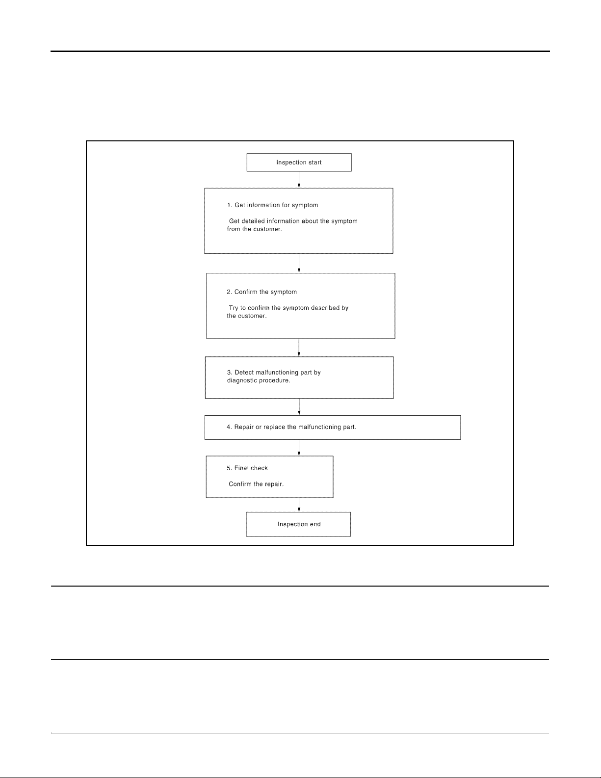
OVERALL SEQUENCE
@KMH @/071FA
DETAILED FLOW
1.GET INFORMATION FOR SYMPTOM
Get detailed information from the customer about the symptom (the condition and the environment when the
incident/malfunction occurred).
>> GO TO 2
2.CONFIRM THE SYMPTOM
Try to confirm the symptom described by the customer. Verify relation between the symptom and the condition
when the symptom is detected.
>> GO TO 3
3.DETECT MALFUNCTIONING PART BY DIAGNOSTIC PROCEDURE
Inspect according to Diagnostic Procedure of the system.
AV-4
Page 10

DIAGNOSIS AND REPAIR WORKFLOW
< BASIC INSPECTION >
Is malfunctioning part detected?
YES >> GO TO 4
NO >> GO TO 2
4.REPAIR OR REPLACE THE MALFUNCTIONING PART
1. Repair or replace the malfunctioning part.
2. Reconnect parts or connectors disconnected during Diagnostic Procedure.
[BASE AUDIO]
A
B
>> GO TO 5
5.FINAL CHECK
Refer to confirmed symptom in step 2, and make sure that the symptom is not detected.
Has the symptom been repaired?
YES >> Inspection End.
NO >> GO TO 2
C
D
E
F
G
H
I
J
AV
K
L
M
O
P
AV-5
Page 11
AUDIO SYSTEM
A
< FUNCTION DIAGNOSIS >
[BASE AUDIO]
FUNCTION DIAGNOSIS
AUDIO SYSTEM
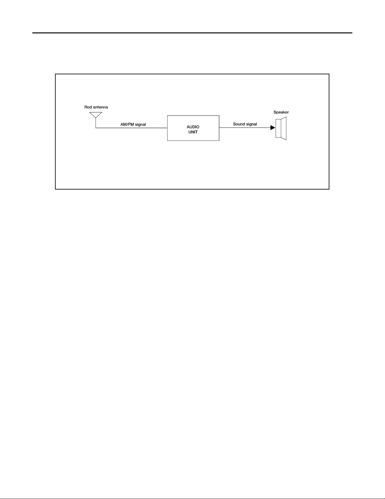
System Diagram INFOID:0000000004095387
@VMH@/677F
System Description INFOID:0000000004095388
AUDIO SYSTEM
The audio system consists of the following components
•Audio unit
•Rod antenna
•Front door speakers
•Front tweeters
•Rear door speakers
When the audio system is on, radio signals are received by the rod antenna. The audio unit then sends audio
signals to the front door speakers, front tweeters and rear door speakers.
Refer to Owner's Manual for audio system operating instructions.
AV-6
Page 12
AUDIO SYSTEM
A
< FUNCTION DIAGNOSIS >
[BASE AUDIO]
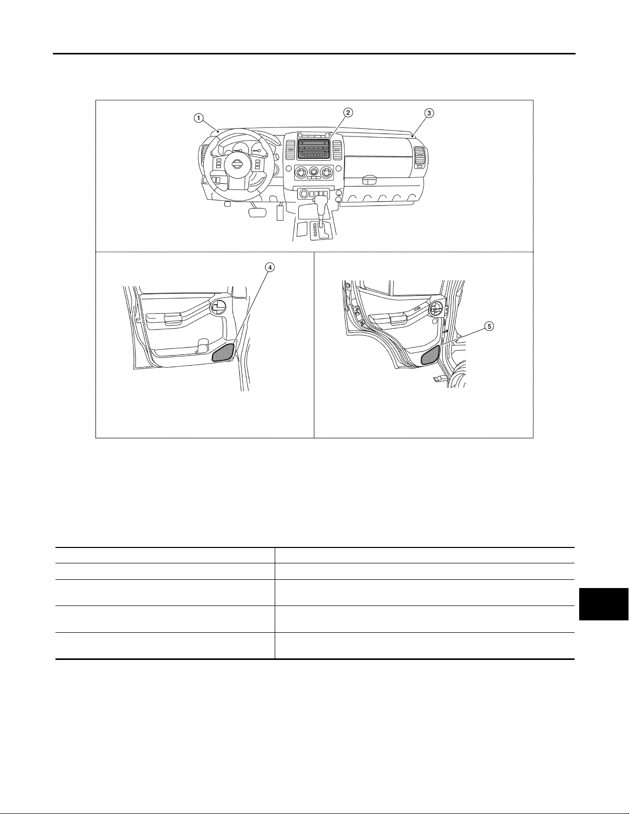
Component Parts Location INFOID:0000000004095389
A
B
C
D
E
F
G
@VMH@/678F
1. Front tweeter LH M109 2. Audio unit M43 3. Front tweeter RH M111
4. Front door speaker
LH D12
RH D112
5. Rear door speaker
LH D207
RH D307
Component Description INFOID:0000000004095390
Part name Description
Audio unit Controls audio system functions
Front door speakers
Front tweeters
Rear door speakers
•Outputs audio signal from audio unit
•Outputs high, mid and low range sounds
•Outputs audio signal from audio unit
•Outputs high range sounds
•Outputs audio signal from audio unit
•Outputs high, mid and low range sounds
H
I
J
K
L
M
AV
O
AV-7
P
Page 13
POWER SUPPLY AND GROUND CIRCUIT
< COMPONENT DIAGNOSIS >
[BASE AUDIO]
COMPONENT DIAGNOSIS
POWER SUPPLY AND GROUND CIRCUIT
AUDIO UNIT
AUDIO UNIT : Diagnosis Procedure INFOID:0000000004095391
1.CHECK FUSES
Check that the following fuses of the audio unit are not are not blown.
Unit Terminals Signal name Fuse No.
Audio unit
Are the fuses OK?
YES >> GO TO 2
NO >> If fuse is blown, be sure to eliminate cause of malfunction before installing new fuse.
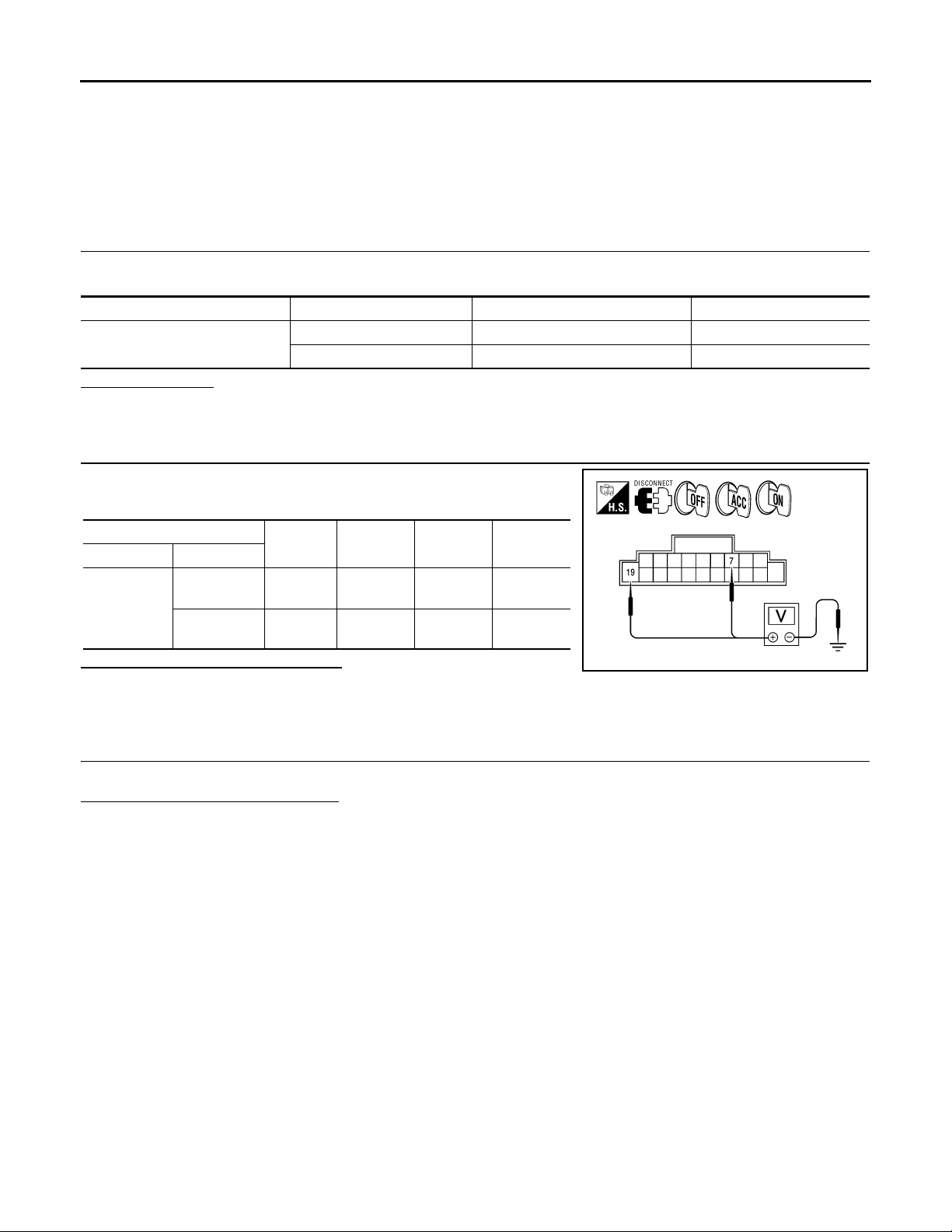
2.POWER SUPPLY CIRCUIT CHECK
1. Disconnect audio unit connector M43.
2. Check voltage between the audio unit connector M43 ground.
19 Battery power 29
7Ignition switch ACC or ON 4
(+)
Connector Terminal
7Ground0V
M43
19 Ground
Are the voltage results as specified?
YES >> GO TO 3
NO >> • Check connector housings for disconnected or loose terminals.
•Repair harness or connector.
(-) OFF ACC ON
Battery
voltage
Battery
voltage
Battery
voltage
Battery
voltage
Battery
voltage
3.GROUND CIRCUIT CHECK
Inspect audio unit case ground.
Does case ground pass inspection?
YES >> Inspection end.
NO >> Repair audio unit case ground.
@KMH@/563FA
AV-8
Page 14
< COMPONENT DIAGNOSIS >
FRONT DOOR SPEAKER
[BASE AUDIO]
FRONT DOOR SPEAKER
Description INFOID:0000000004095392
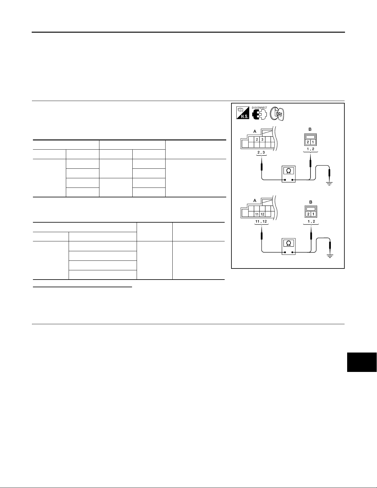
The audio unit sends audio signals to the front door speakers using the front door speaker circuits.
Diagnosis Procedure INFOID:0000000004095393
1.HARNESS CHECK
1. Disconnect audio unit connector M43 and suspect speaker connector.
2. Check continuity between audio unit harness connector M43 (A)
terminal and suspect speaker harness connector (B) terminal.
AB
Connector Terminal Connector Terminal
M43
2
32
11
12 2
D12
D112
1
1
Continuity
Yes
3. Check continuity between audio unit harness connector M43 (A)
terminal and ground.
A
Connector Terminal
2
M43
3
11
12
—Continuity
Ground No
@VMH@//20YY
Are continuity results as specified?
YES >> GO TO 2
NO >> • Check connector housings for disconnected or loose terminals.
•Repair harness or connector.
2.FRONT SPEAKER SIGNAL CHECK
A
B
C
D
E
F
G
H
I
J
K
L
AV-9
M
AV
O
P
Page 15
FRONT DOOR SPEAKER
< COMPONENT DIAGNOSIS >
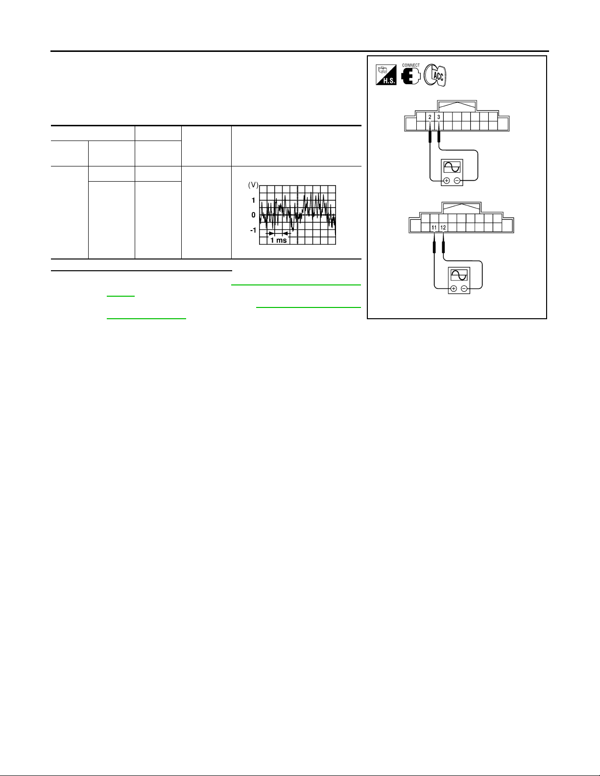
1. Connect audio unit connector M43 and front speaker connector.
2. Turn ignition switch to ACC.
3. Push “POWER” switch.
4. Check the signal between audio unit harness connector M43
terminals with CONSULT-III or oscilloscope.
(+) (-)
Con-
nector
M43
Te rm ina l Te r mi n al
23
11 12
Is the audio signal voltage as specified?
YES >> Replace speaker. Refer to AV- 31, " Removal and Instal-
lation".
NO >> Replace audio unit. Refer to AV- 27, "
Installation-2DIN".
Condition Reference signal
Receive
audio signal
RJ H@/066D
Removal and
[BASE AUDIO]
@VMH@//21YY
AV-10
Page 16
< COMPONENT DIAGNOSIS >
FRONT TWEETER
[BASE AUDIO]
FRONT TWEETER
Description INFOID:0000000004095394
The audio unit sends audio signals to the front tweeters using the front tweeter circuits.
Diagnosis Procedure INFOID:0000000004095395
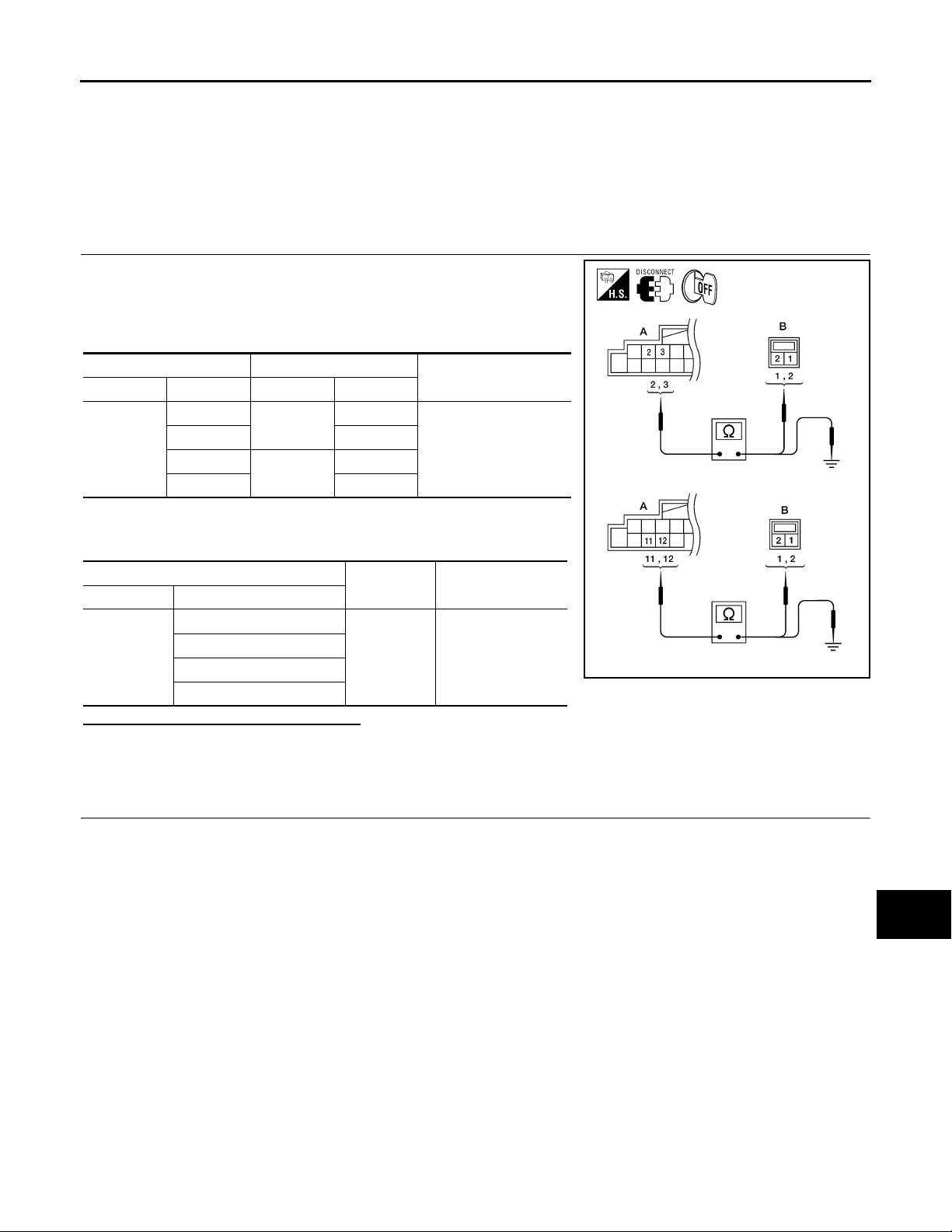
1.HARNESS CHECK
1. Disconnect audio unit connector M43 and suspect front tweeter
connector.
2. Check continuity between audio unit harness connector M43 (A)
and suspect front tweeter harness connector (B).
AB
Connector Terminal Connector Terminal
M43
2
32
11
12 2
M109
M111
1
1
Continuity
Yes
3. Check continuity between audio unit harness connector M43 (A)
and ground.
A
Connector Terminal
2
M43
3
11
12
—Continuity
Ground No
@VMH@//20YY
Are the continuity results as specified?
YES >> GO TO 2
NO >> • Check connector housings for disconnected or loose terminals.
•Repair harness or connector.
2.FRONT TWEETER SIGNAL CHECK
A
B
C
D
E
F
G
H
I
J
K
L
AV-11
M
AV
O
P
Page 17
FRONT TWEETER
< COMPONENT DIAGNOSIS >
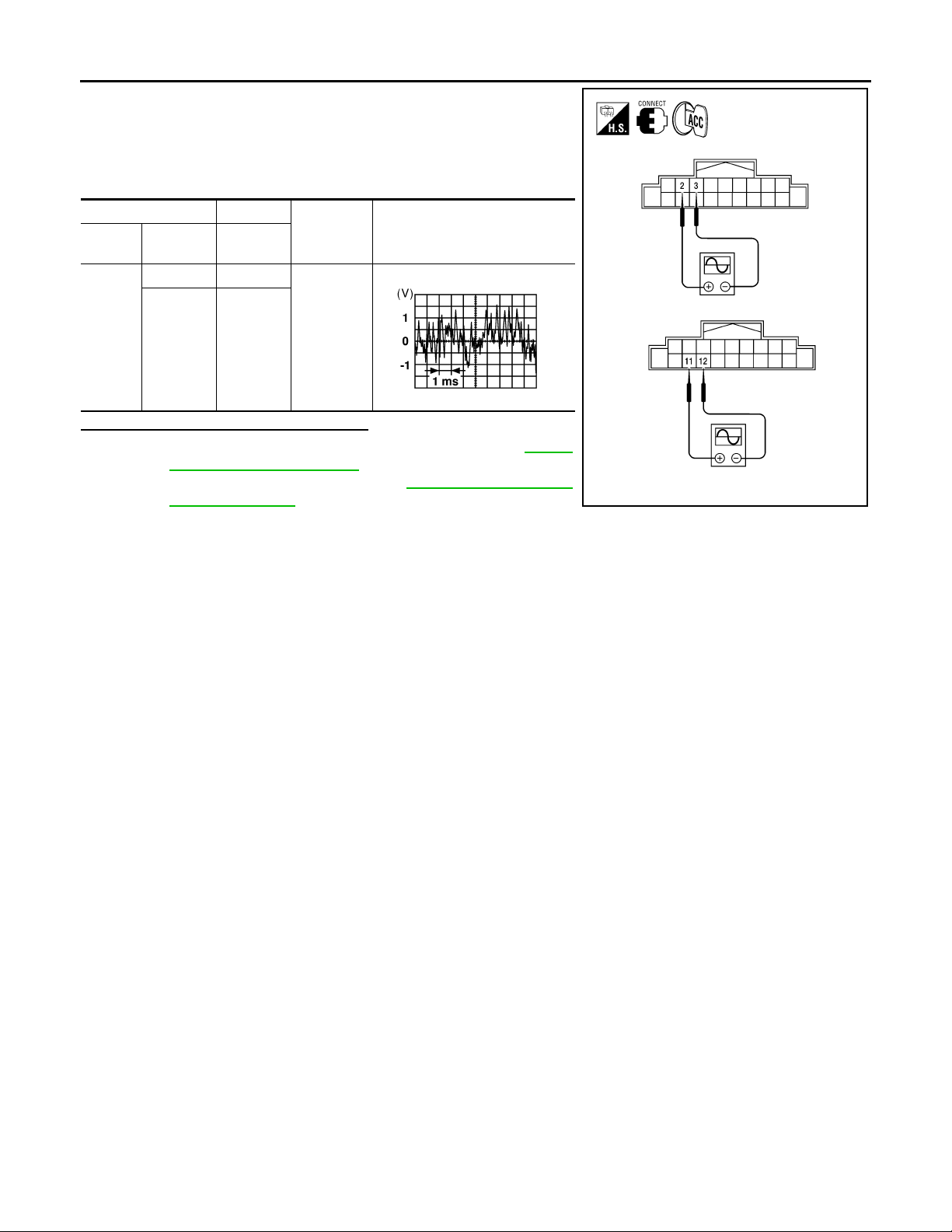
1. Connect audio unit connector M43 and front tweeter connector.
2. Turn ignition switch to ACC.
3. Push “POWER” switch.
4. Check the signal between audio unit harness connector M43
terminals with CONSULT-III or oscilloscope.
(+) (-)
Con-
nector
M43
Te rm i n al Te rm i n al
23
11 12
Is the audio signal voltage as specified?
YES >> Replace the suspect front tweeter. Refer to AV-30 ,
"Removal and Installation".
NO >> Replace audio unit. Refer to AV- 27, "
Installation-2DIN".
Condition Reference signal
Receive
audio signal
RJ H@/066D
Removal and
[BASE AUDIO]
@VMH@//21YY
AV-12
Page 18
< COMPONENT DIAGNOSIS >
REAR DOOR SPEAKER
[BASE AUDIO]
REAR DOOR SPEAKER
Description INFOID:0000000004095396
The audio unit sends audio signals to the rear door speakers using the rear door speaker circuits.
Diagnosis Procedure INFOID:0000000004095397
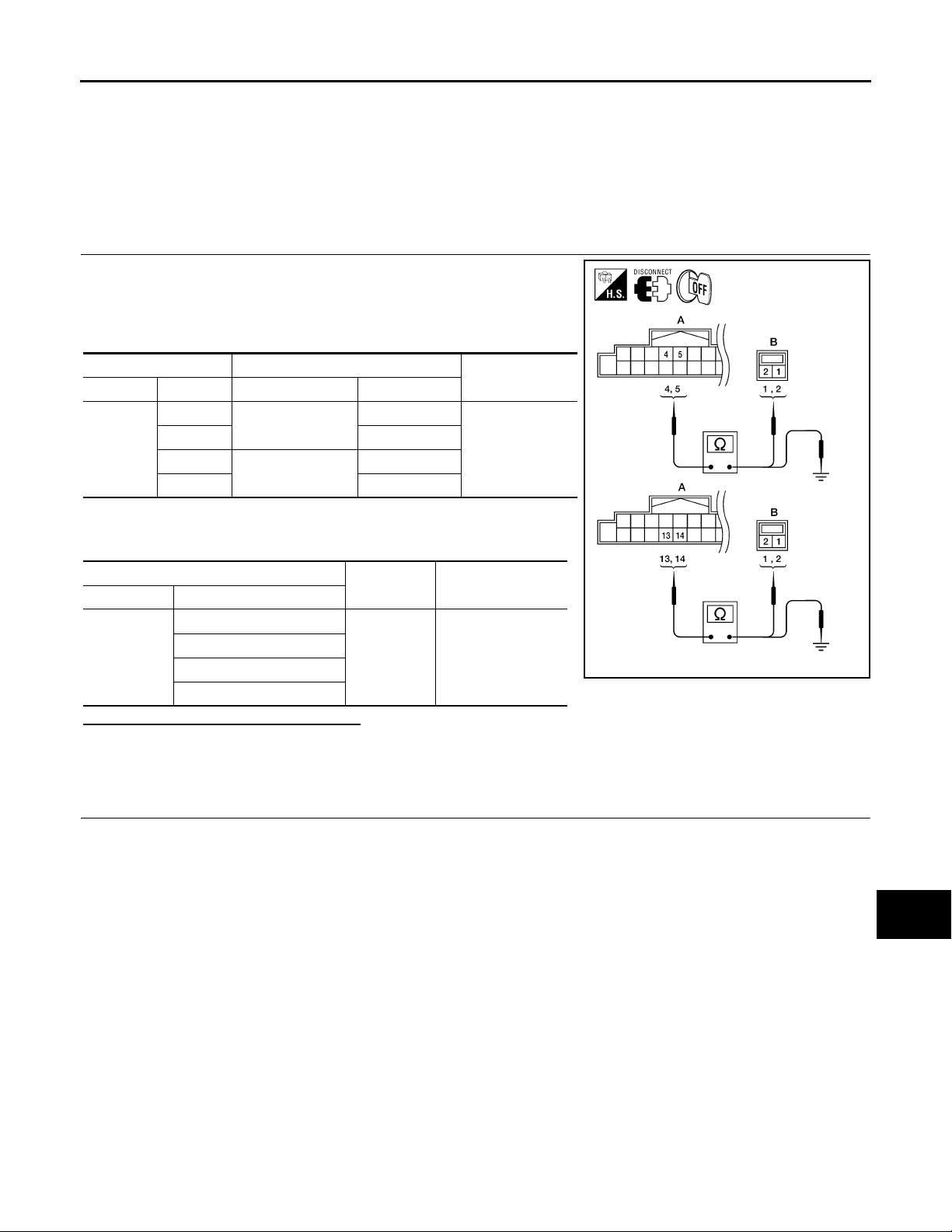
1.HARNESS CHECK
1. Disconnect audio unit connector M43 and suspect rear door
speaker connector.
2. Check continuity between audio unit harness connector M43 (A)
and suspect rear door speaker harness connector (B).
A B
Connector Terminal Connector Terminal
M43
4
52
13
14 2
D207
D307
1
1
Continuity
Yes
3. Check continuity between audio unit harness connector M43 (A)
and ground.
A
Connector Terminal
4
M43
5
13
14
—Continuity
Ground No
@VMH@//22YY
Are the continuity results as specified?
YES >> GO TO 2
NO >> • Check connector housings for disconnected or loose terminals.
•Repair harness or connector.
2.REAR DOOR SPEAKER SIGNAL CHECK
A
B
C
D
E
F
G
H
I
J
K
L
AV-13
M
AV
O
P
Page 19
REAR DOOR SPEAKER
< COMPONENT DIAGNOSIS >
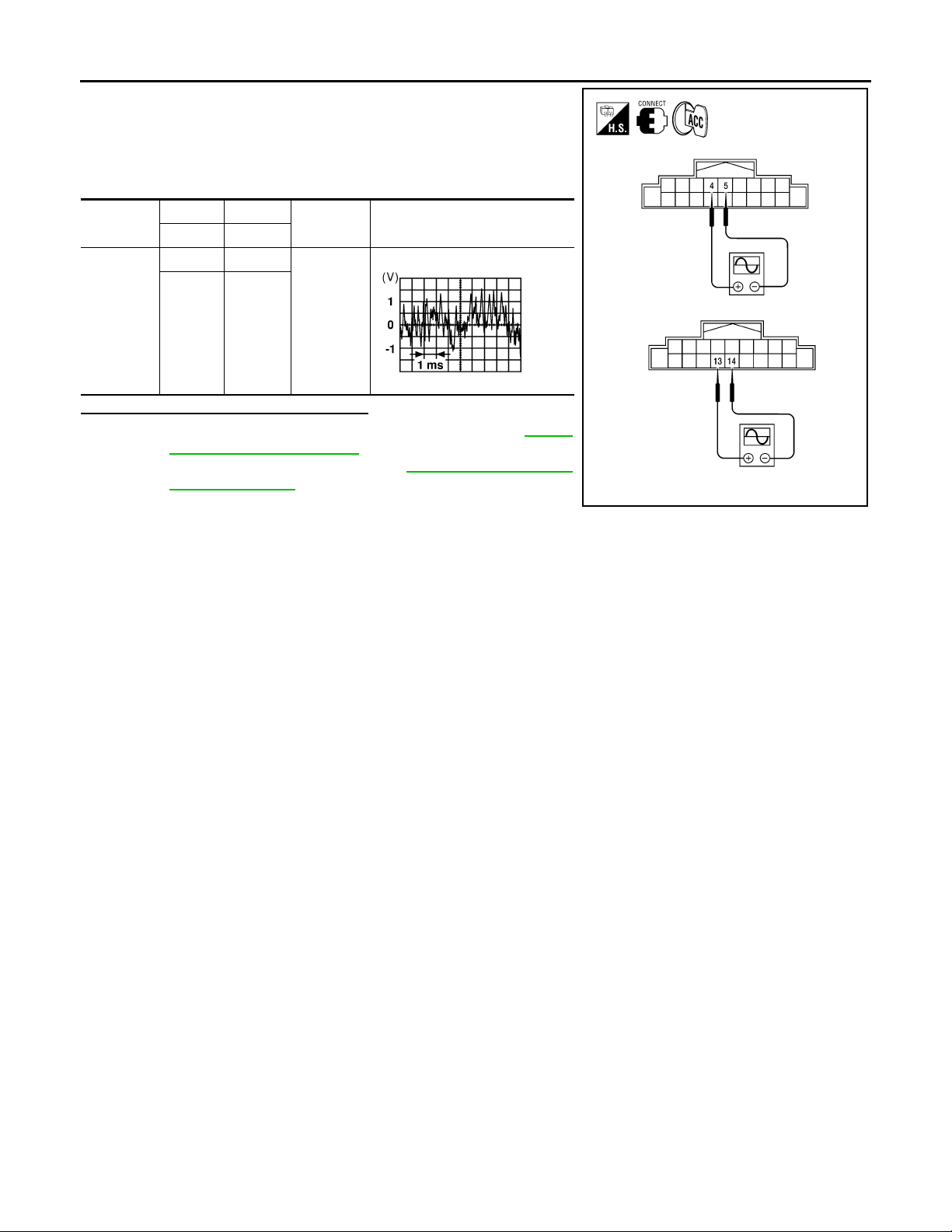
1. Connect audio unit connector and rear door speaker connector.
2. Turn ignition switch to ACC.
3. Push “POWER” switch.
4. Check the signal between audio unit harness connector M43
terminals with CONSULT-III or oscilloscope.
[BASE AUDIO]
Connector
M43
(+) (-)
Te rm in al Te rm i na l
45
13 14
Condition Reference signal
Receive
audio signal
RJ H@/066D
Is the audio signal voltage as specified?
YES >> Replace the suspect rear door speaker. Refer to AV-32 ,
"Removal and Installation".
NO >> Replace audio unit. Refer to AV- 27, "
Removal and
Installation-2DIN".
@VMH@//23YY
AV-14
Page 20
< ECU DIAGNOSIS >
AUDIO UNIT
[BASE AUDIO]
ECU DIAGNOSIS
AUDIO UNIT
Reference Value INFOID:0000000004095398
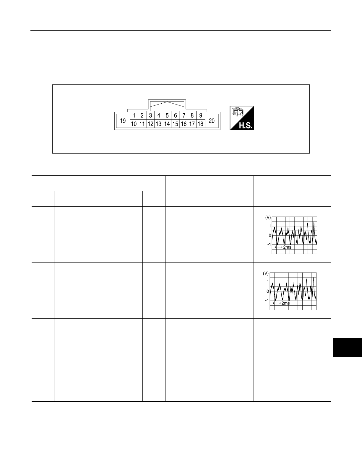
TERMINAL LAYOUT
@VMH@0663YY
PHYSICAL VALUES
Te rm i na l
(Wire color)
+– Signal name
Description
Input/
Output
Condition
Reference value
(Approx.)
A
B
C
D
E
F
G
H
2
(BR)
4
(G)
7
(G/B)
8
(GR)
9
(R)
Sound signal front door
3
speaker and front tweeter LHOutput
(L)
5
Sound signal rear door
(B)
speaker LH
Ground ACC power supply Input
Ground ILL control Input
Ground Light switch Input
Output
Ignition
switch ONAudio output
Ignition
switch ONAudio output
Ignition
switch
ACC or
ON
Ignition
switch
ACC or
ON
Ignition
switch
ACC or
ON
I
RJ HA25/ 8D
J
K
L
RJ HA25/ 8D
M
—Battery voltage
AV
—0V
O
—Battery voltage
P
AV-15
Page 21
< ECU DIAGNOSIS >
AUDIO UNIT
[BASE AUDIO]
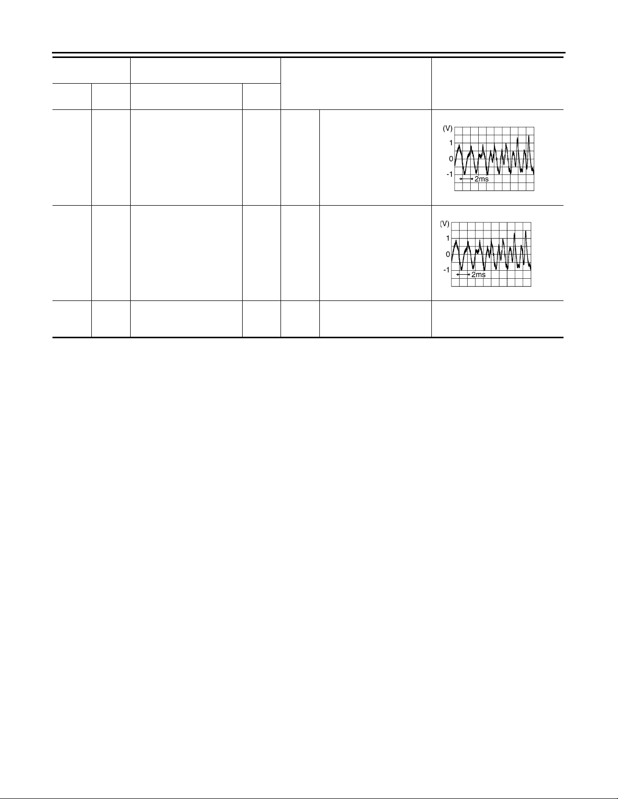
Te rm i na l
(Wire color)
+– Signal name
11
(LG)
13
(GR)
19
(Y)
Ground Battery power supply Input
Sound signal front door
12
speaker and front tweeter RHOutput
(R)
14
Sound signal rear door
(O)
speaker RH
Description
Input/
Output
Output
Condition
Ignition
switch ONVoice output
Ignition
switch ONVoice output
Ignition
switch
OFF
Reference value
(Approx.)
RJ HA25/ 8D
RJ HA25/ 8D
—Battery voltage
AV-16
Page 22
AUDIO UNIT
A
< ECU DIAGNOSIS >
[BASE AUDIO]
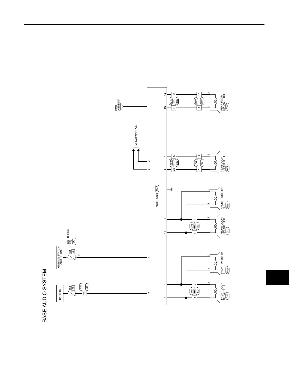
Wiring Diagram INFOID:0000000004095399
A
B
C
D
E
F
G
AV
H
I
J
K
L
M
O
AV-17
P
@@MV @ //25F
Page 23
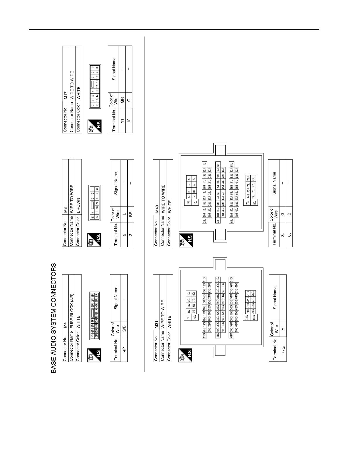
< ECU DIAGNOSIS >
AUDIO UNIT
[BASE AUDIO]
AV-18
@AMH@/444FA
Page 24
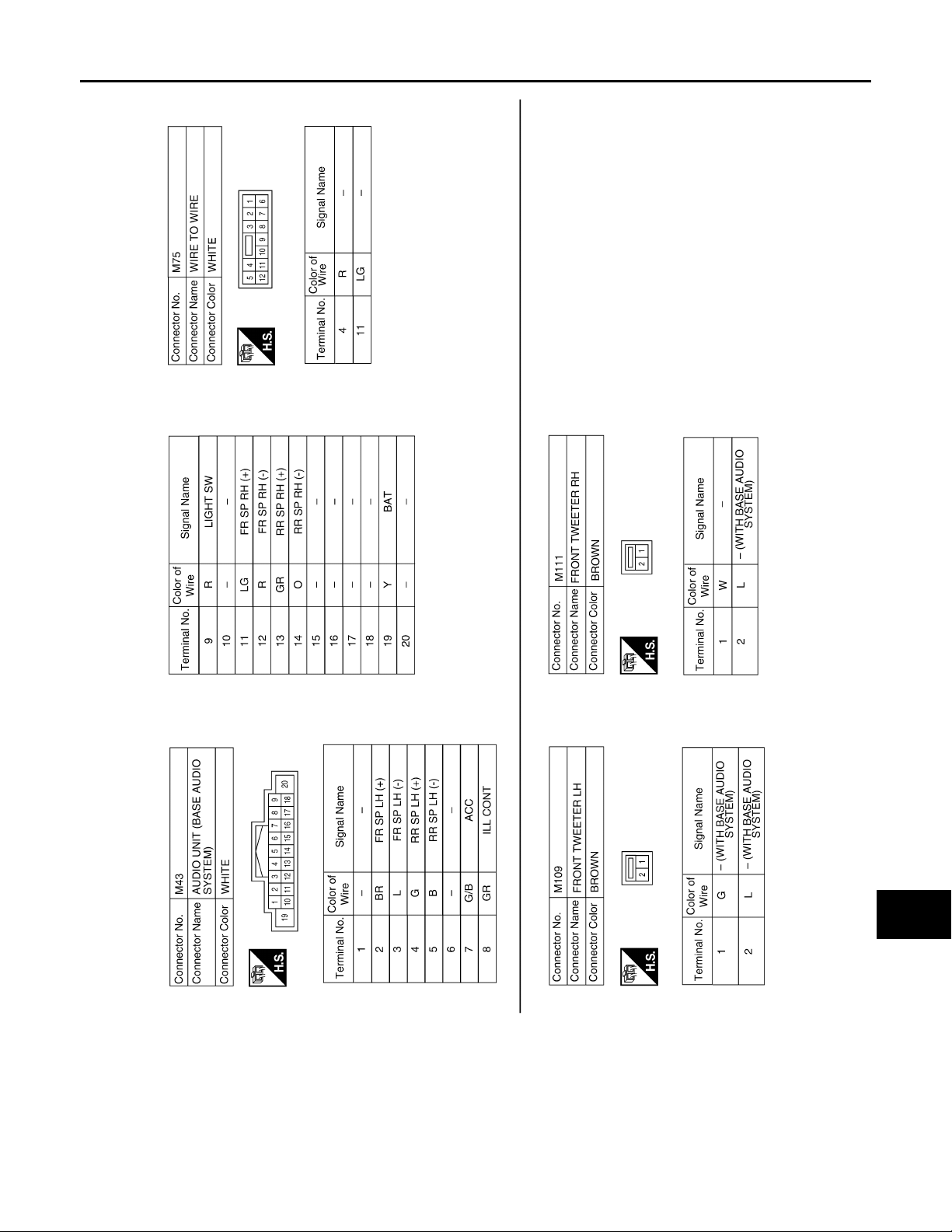
< ECU DIAGNOSIS >
AUDIO UNIT
[BASE AUDIO]
A
B
C
D
E
F
G
AV
H
I
J
K
L
M
O
AV-19
@AMH@/445FA
P
Page 25
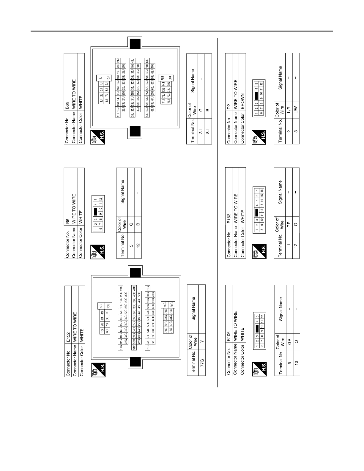
< ECU DIAGNOSIS >
AUDIO UNIT
[BASE AUDIO]
AV-20
@AMH@/446FA
Page 26
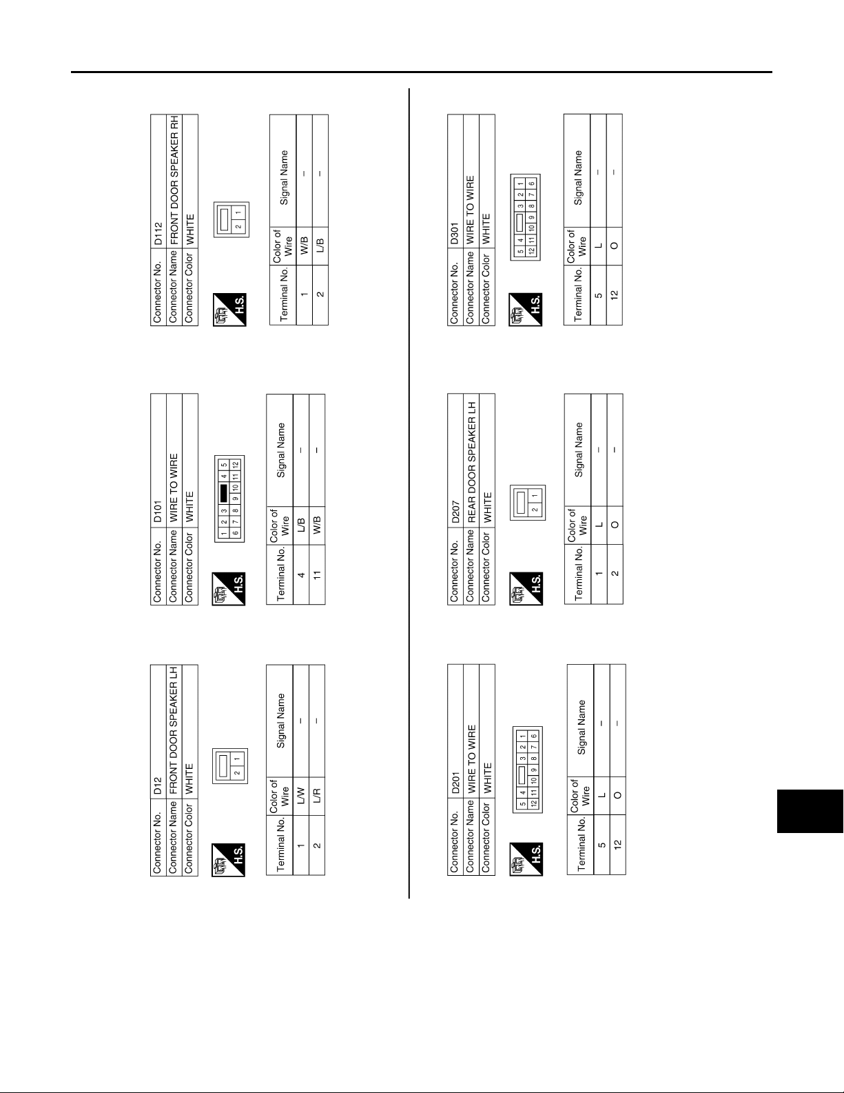
< ECU DIAGNOSIS >
AUDIO UNIT
[BASE AUDIO]
A
B
C
D
E
F
G
AV
H
I
J
K
L
M
O
AV-21
@AMH@/447FA
P
Page 27
< ECU DIAGNOSIS >
A
AUDIO UNIT
[BASE AUDIO]
AV-22
@VMH@/542F
Page 28
< SYMPTOM DIAGNOSIS >
AUDIO SYSTEM
[BASE AUDIO]
SYMPTOM DIAGNOSIS
AUDIO SYSTEM
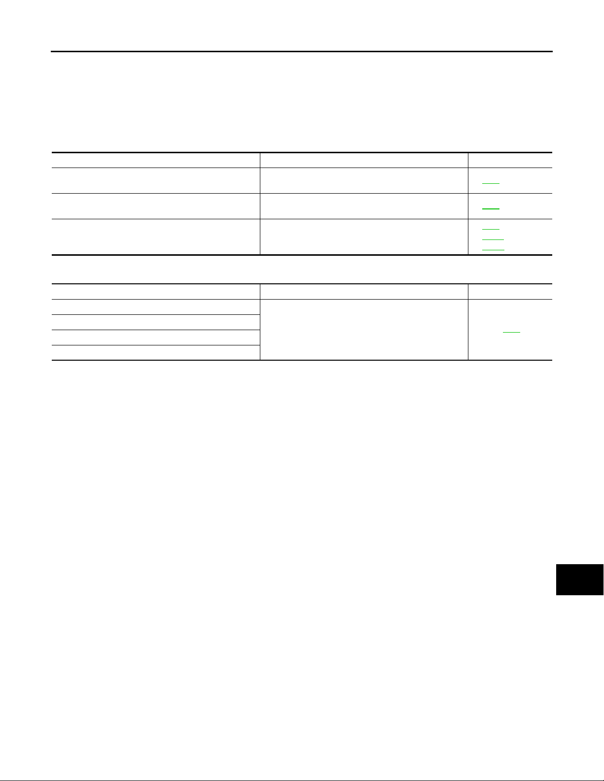
Symptom Table INFOID:0000000004095400
AUDIO SYSTEM
Symptom Possible cause Reference page
Inoperative
All speakers do not sound
One or several speakers do not sound
CD
Symptom Possible cause Reference page
CD cannot be inserted.
CD cannot be ejected.
The CD cannot be played.
The sound skips, stops suddenly, or is distorted.
•Audio unit power circuit
•Audio unit
•Audio unit
•Audio unit power circuit
•Front door speaker
•Front tweeter
•Rear door speaker
Audio unit AV-8
• AV-8
• AV-8
• AV-9
• AV-11
• AV-13
A
B
C
D
E
F
G
H
AV
I
J
K
L
M
O
P
AV-23
Page 29

NORMAL OPERATING CONDITION
< SYMPTOM DIAGNOSIS >
[BASE AUDIO]
NORMAL OPERATING CONDITION
Description INFOID:0000000004095401
The majority of the audio concerns are the result of outside causes (bad CD, electromagnetic interference,
etc.).
NOISE
The following noise results from variations in field strength, such as fading noise and multi-path noise, or
external noise from trains and other sources. It is not a malfunction.
•Fading noise: This noise occurs because of variations in the field strength in a narrow range due to moun-
tains or buildings blocking the signal.
•Multi-path noise: This noise results from the waves sent directly from the broadcast station arriving at the
antenna at a different time from the waves which reflect off mountains or buildings.
The vehicle itself can be a source of noise if noise prevention parts or electrical equipment is malfunctioning.
Check if noise is caused and/or changed by engine speed, ignition switch turned to each position, and operation of each piece of electrical equipment, and determine the cause.
NOTE:
The source of the noise can be found easily by listening to the noise while removing the fuses of electrical
components, one by one.
Type of Noise and Possible Cause
Occurrence condition Possible cause
Occurs only when engine is ON.
The occurrence of the noise is linked with the operation of the fuel pump. • Fuel pump condenser
Noise only occurs when various
electrical components are operating.
The noise occurs constantly, not just under certain conditions.
A cracking or snapping sound occurs while the vehicle is being driven, especially when
it is vibrating excessively.
A continuous growling noise occurs. The speed of
the noise varies with changes in the engine speed.
A cracking or snapping sound occurs with the operation of various switches.
The noise occurs when various motors are operating.
•Ignition components
•Relay malfunction, audio unit malfunction
•Motor case ground
•Motor
•Rear defogger coil malfunction
•Open circuit in printed heater
•Poor ground of antenna feeder line
•Ground wire of body parts
•Ground due to improper part installation
•Wiring connections or a short circuit
AV-24
Page 30

< PRECAUTION >
PRECAUTIONS
[BASE AUDIO]
PRECAUTION
PRECAUTIONS
Precaution for Supplemental Restraint System (SRS) "AIR BAG" and "SEAT BELT
PRE-TENSIONER" INFOID:0000000004095402
The Supplemental Restraint System such as “AIR BAG” and “SEAT BELT PRE-TENSIONER”, used along
with a front seat belt, helps to reduce the risk or severity of injury to the driver and front passenger for certain
types of collision. This system includes seat belt switch inputs and dual stage front air bag modules. The SRS
system uses the seat belt switches to determine the front air bag deployment, and may only deploy one front
air bag, depending on the severity of a collision and whether the front occupants are belted or unbelted.
Information necessary to service the system safely is included in the SR and SB sections of this Service Manual.
WARNING:
•To avoid rendering the SRS inoperative, which could increase the risk of personal injury or death in
the event of a collision which would result in air bag inflation, all maintenance must be performed by
an authorized NISSAN/INFINITI dealer.
•Improper maintenance, including incorrect removal and installation of the SRS, can lead to personal
injury caused by unintentional activation of the system. For removal of Spiral Cable and Air Bag
Module, see the SR section.
•Do not use electrical test equipment on any circuit related to the SRS unless instructed to in this
Service Manual. SRS wiring harnesses can be identified by yellow and/or orange harnesses or harness connectors.
A
B
C
D
E
F
G
H
AV
I
J
K
L
M
O
P
AV-25
Page 31
PREPARATION
< PREPARATION >
[BASE AUDIO]
PREPARATION
PREPARATION
Commercial Service Tools INFOID:0000000004095403
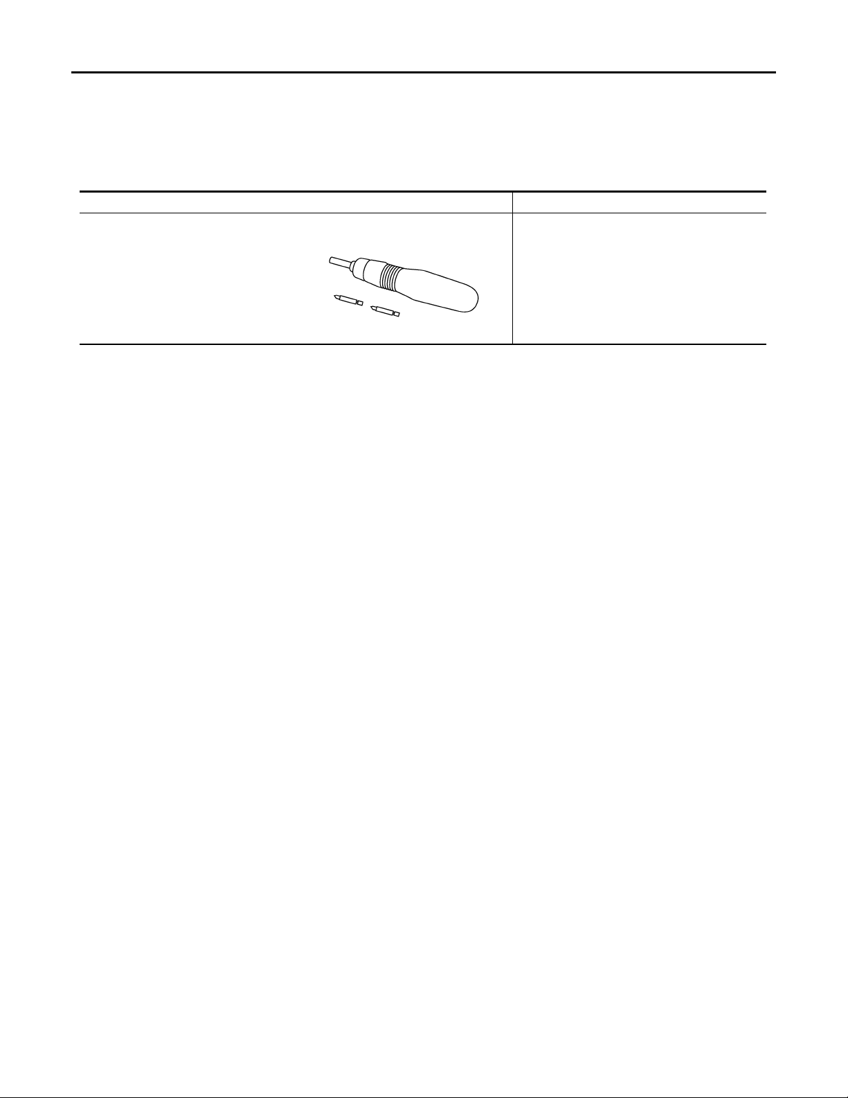
To ol nam e Description
Loosening bolts and nuts
Power tool
OAH B/080D
AV-26
Page 32
< ON-VEHICLE REPAIR >
AUDIO UNIT
[BASE AUDIO]
ON-VEHICLE REPAIR
AUDIO UNIT
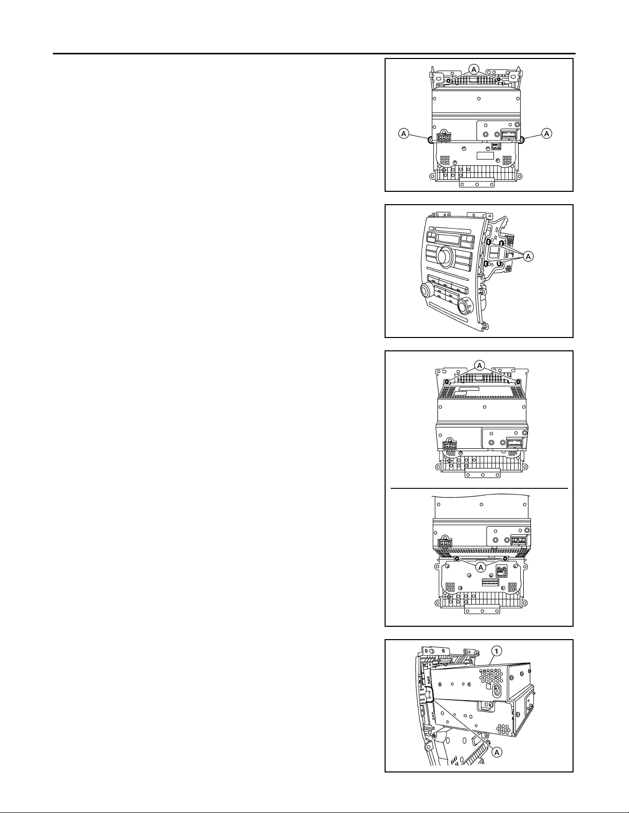
Removal and Installation-2DIN INFOID:0000000004095404
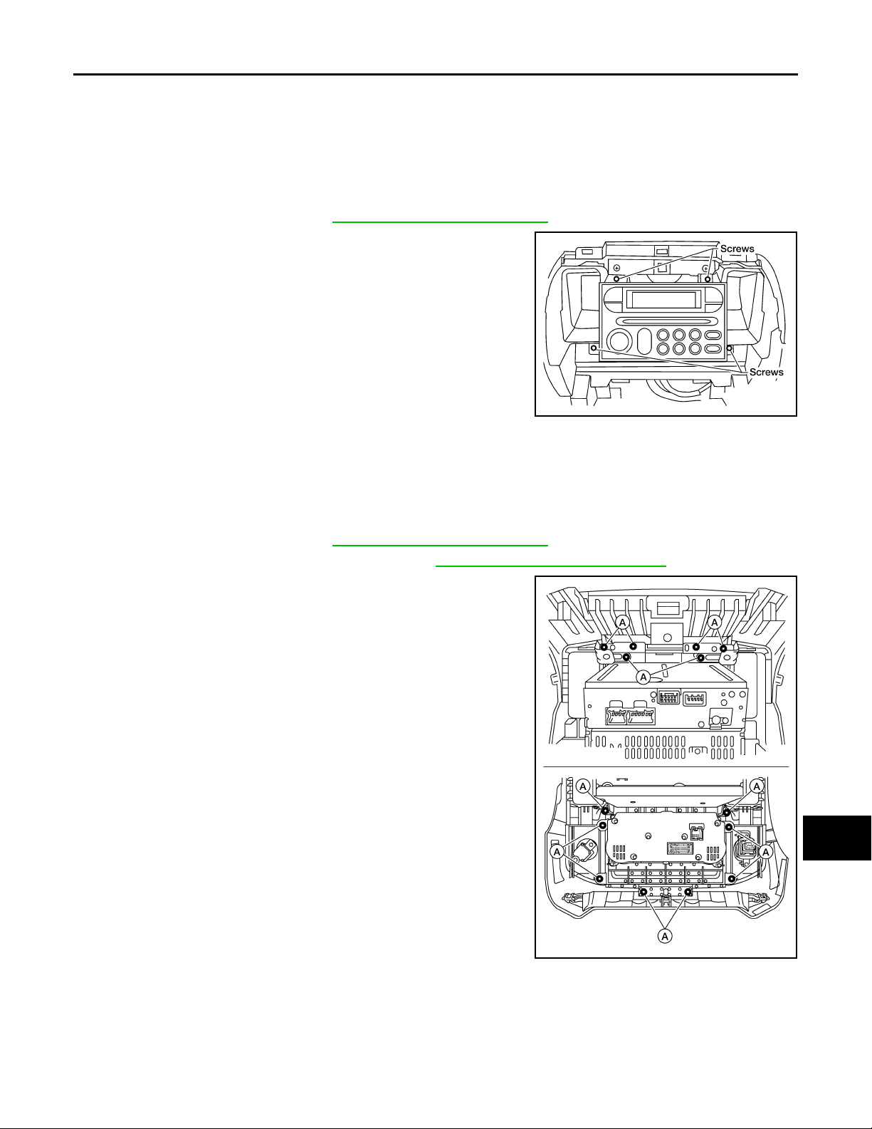
REMOVAL
1. Remove the cluster lid C. Refer to IP-11, "Removal and Installation".
2. Remove the audio unit screws, using power tool.
3. Pull out the audio unit from the instrument panel and disconnect
the audio unit connectors.
4. Remove the audio unit bracket screws and remove the audio
unit brackets.
KJ H @/471D
INSTALLATION
Installation is in the reverse order of removal.
Removal and Installation-0DIN INFOID:0000000004471322
REMOVAL
1. Remove the cluster lid C. Refer to IP-11, "Removal and Installation".
2. Remove the RH and LH ventilator grilles. Refer to VTL-21, "
3. Remove the audio unit assembly screws (A), then remove the
audio unit assembly, from cluster lid C.
Removal and Installation".
A
B
C
D
E
F
G
H
I
J
@KMH@0075YY
K
L
M
AV
O
P
AV-27
Page 33
AUDIO UNIT
< ON-VEHICLE REPAIR >
4. Remove the audio unit bracket screws (A).
5. Remove the audio unit RH/LH bracket screws (A), using power
tool and remove the audio unit brackets.
[BASE AUDIO]
@KMH@0077YY
6. Remove the audio unit screws (A), using power tool.
@KMH@0078YY
@KMH@008/ YY
7. Release the audio unit tab (A) and remove the audio unit (1).
AV-28
@KMH@0080YY
Page 34

< ON-VEHICLE REPAIR >
INSTALLATION
Installation is in the reverse order of removal.
AUDIO UNIT
[BASE AUDIO]
A
B
C
D
E
F
G
AV
H
I
J
K
L
M
O
AV-29
P
Page 35
FRONT TWEETER
< ON-VEHICLE REPAIR >
[BASE AUDIO]
FRONT TWEETER
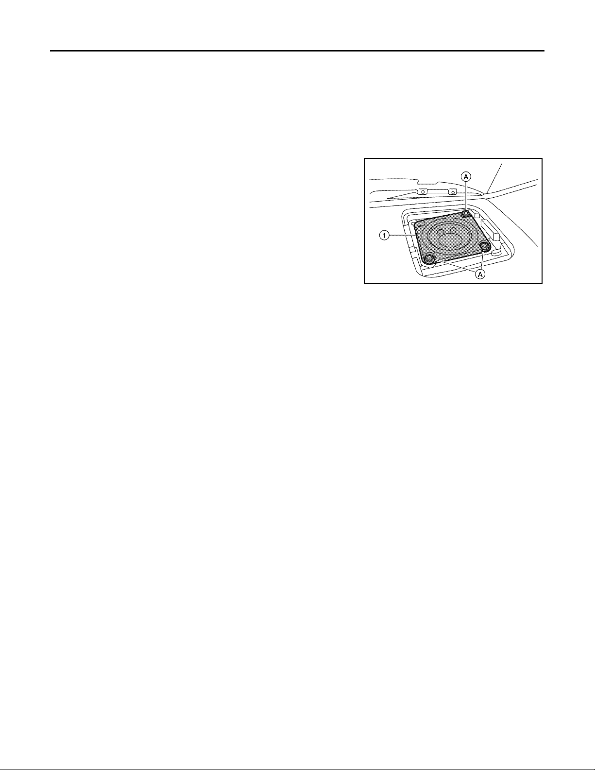
Removal and Installation INFOID:0000000004095405
REMOVAL
CAUTION:
Use a suitable tool to prevent damage to the front tweeter speaker grille trim and the instrument panel.
1. Remove the front tweeter grille.
2. Remove the front tweeter screws (A).
3. Pull out the front tweeter speaker (1) and disconnect front
tweeter connector, then remove the front tweeter speaker (1).
@KMH@/233YY
INSTALLATION
Installation is in the reverse order of removal.
AV-30
Page 36
< ON-VEHICLE REPAIR >
FRONT DOOR SPEAKER
[BASE AUDIO]
FRONT DOOR SPEAKER
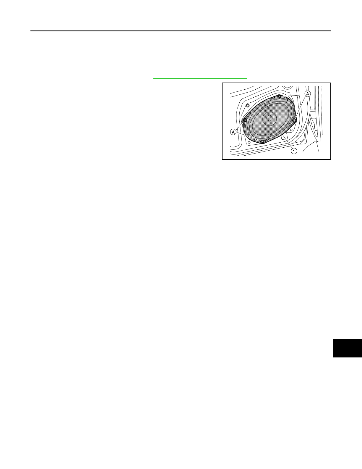
Removal and Installation INFOID:0000000004095406
REMOVAL
1. Remove the front door finisher. Refer to INT-13, "Removal and Installation".
2. Remove the front door speaker screws (A).
3. Pull out the front door speaker (1), and disconnect the front door
speaker connector and remove the front door speaker (1).
@KMH@/236YY
INSTALLATION
Installation is in the reverse order of removal.
A
B
C
D
E
F
G
H
AV
I
J
K
L
M
O
P
AV-31
Page 37
REAR DOOR SPEAKER
< ON-VEHICLE REPAIR >
[BASE AUDIO]
REAR DOOR SPEAKER
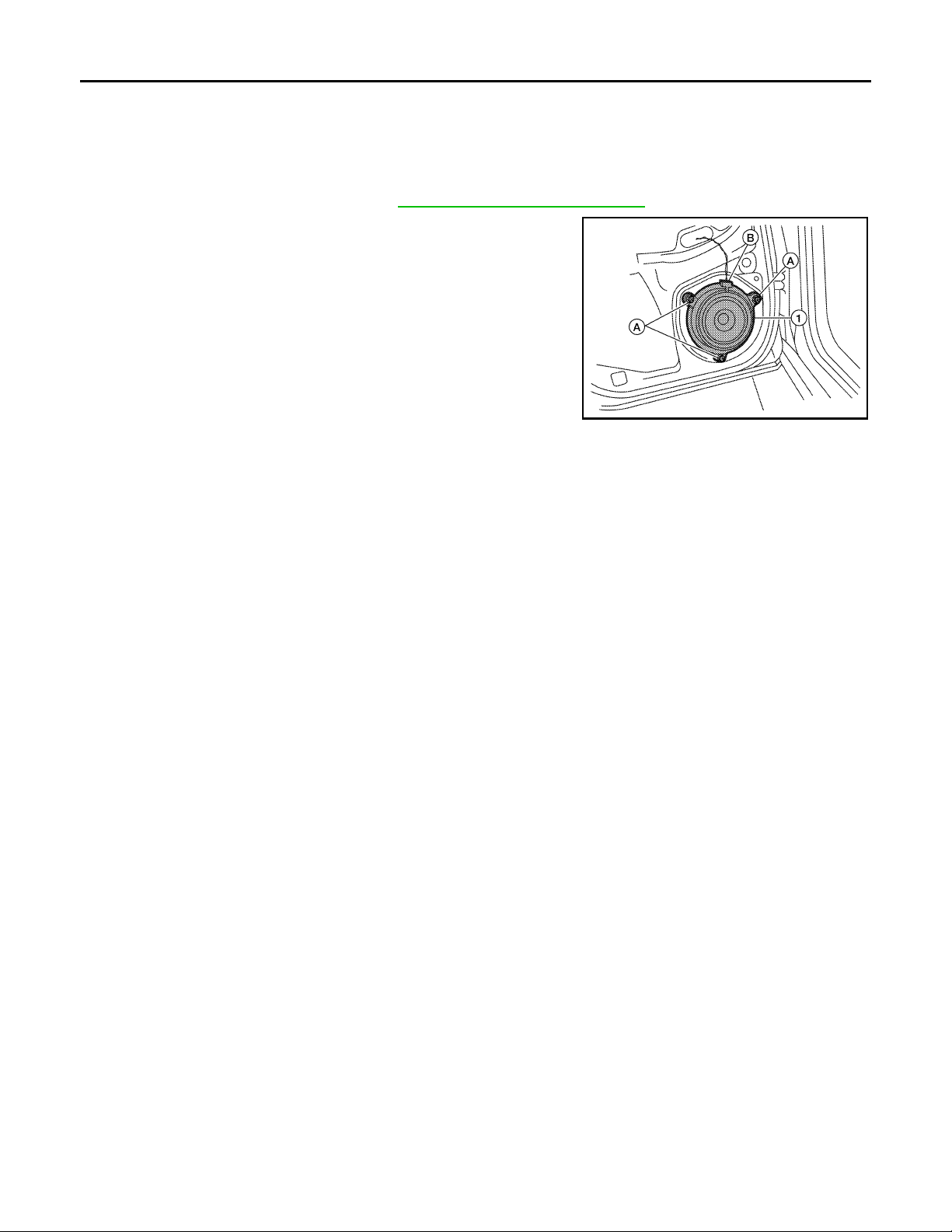
Removal and Installation INFOID:0000000004095407
REMOVAL
1. Remove the rear door finisher. Refer to INT-13, "Removal and Installation".
2. Remove the rear door speaker screws (A).
3. Disconnect the rear door speaker connector (B) and remove
rear door speaker (1).
@KMH@/237YY
INSTALLATION
Installation is in the reverse order of removal.
AV-32
Page 38
< ON-VEHICLE REPAIR >
AUDIO ANTENNA
[BASE AUDIO]
AUDIO ANTENNA
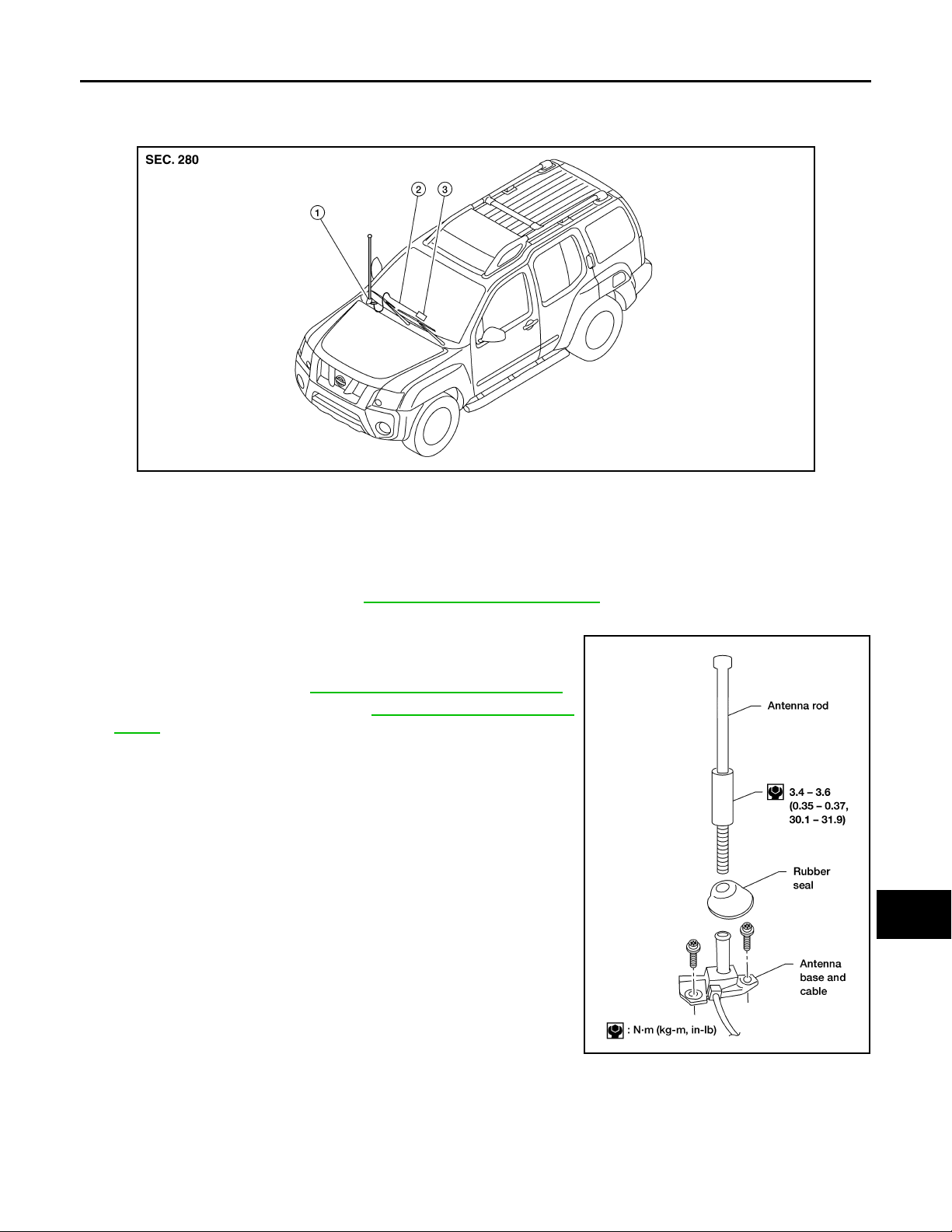
Location of Audio Antenna System Component INFOID:0000000004095408
1. Audio antenna 2. Antenna feeder 3. Audio unit
Removal and Installation INFOID:0000000004095409
REMOVAL
1. Remove lower glove box. Refer to IP-11, "Removal and Installation".
2. Disconnect audio antenna cable from antenna feeder.
3. Remove antenna rod.
4. Remove rubber seal.
5. Remove cowl top. Refer to EXT-17, "
6. Remove fender protector. Refer to EXT-19, "
tector".
7. Remove antenna base bolts.
8. Remove antenna base and cable.
Removal and Installation".
Front Fender Pro-
A
B
C
D
E
F
G
H
I
J
K
L
@DK50 / B
INSTALLATION
Installation is in the reverse order of removal.
CAUTION:
Always properly tighten the antenna rod during installation or the antenna rod may bend or break during vehicle operation.
AV-33
M
AV
O
P
Page 39
DIAGNOSIS AND REPAIR WORKFLOW
< BASIC INSPECTION >
[PREMIUM AUDIO]
BASIC INSPECTION
DIAGNOSIS AND REPAIR WORKFLOW
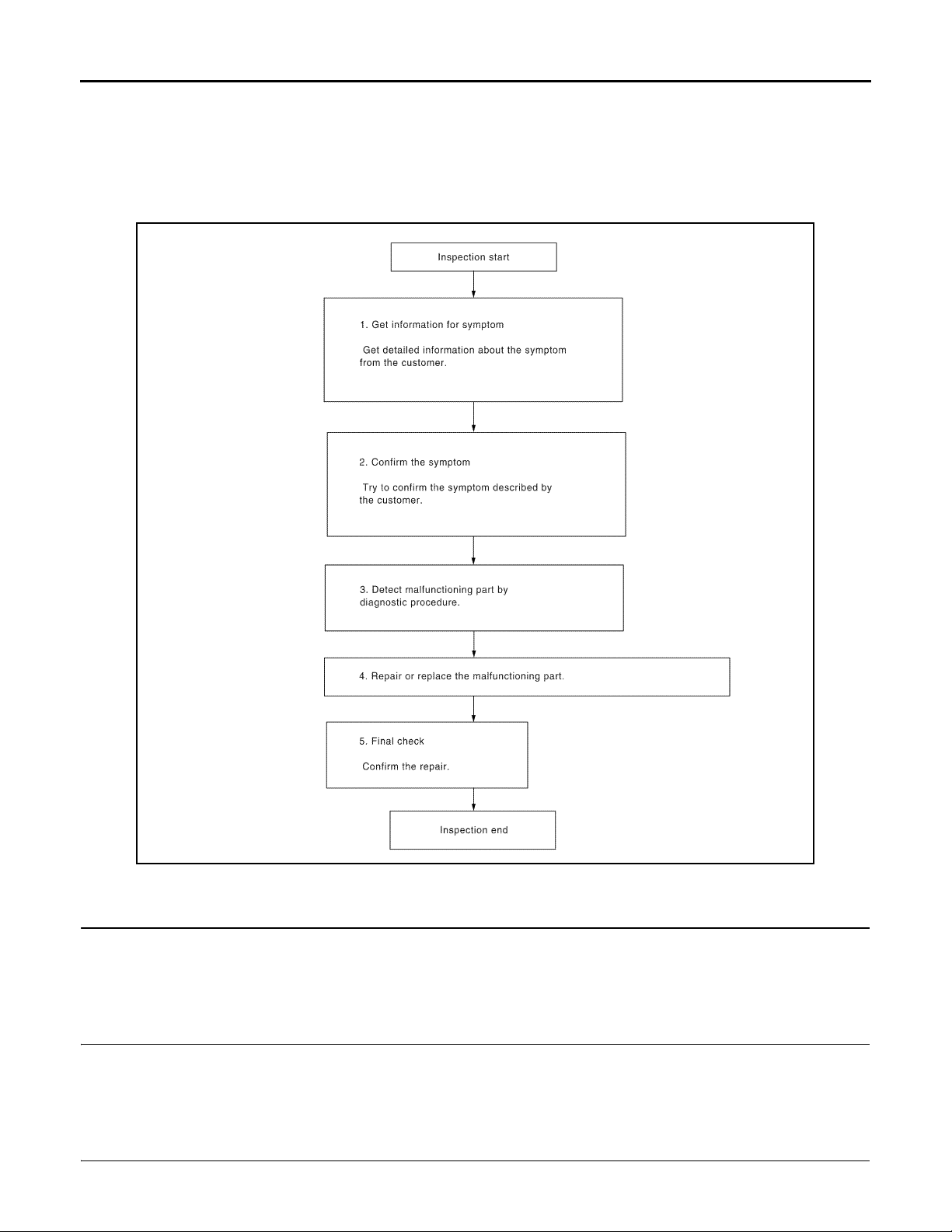
Work Flow INFOID:0000000004095410
OVERALL SEQUENCE
@KMH @/071FA
DETAILED FLOW
1.GET INFORMATION FOR SYMPTOM
Get detailed information from the customer about the symptom (the condition and the environment when the
incident/malfunction occurred).
>> GO TO 2
2.CONFIRM THE SYMPTOM
Try to confirm the symptom described by the customer. Verify relation between the symptom and the condition
when the symptom is detected.
>> GO TO 3
3.DETECT MALFUNCTIONING PART BY DIAGNOSTIC PROCEDURE
Inspect according to Diagnostic Procedure of the system.
AV-34
Page 40

DIAGNOSIS AND REPAIR WORKFLOW
< BASIC INSPECTION >
Is malfunctioning part detected?
YES >> GO TO 4
NO >> GO TO 2
4.REPAIR OR REPLACE THE MALFUNCTIONING PART
1. Repair or replace the malfunctioning part.
2. Reconnect parts or connectors disconnected during Diagnostic Procedure.
[PREMIUM AUDIO]
A
B
>> GO TO 5
5.FINAL CHECK
Refer to confirmed symptom in step 2, and make sure that the symptom is not detected.
Was the repair confirmed?
YES >> Inspection End.
NO >> GO TO 2
C
D
E
F
G
H
I
J
AV
K
L
M
O
P
AV-35
Page 41
AUDIO SYSTEM
A
< FUNCTION DIAGNOSIS >
[PREMIUM AUDIO]
FUNCTION DIAGNOSIS
AUDIO SYSTEM
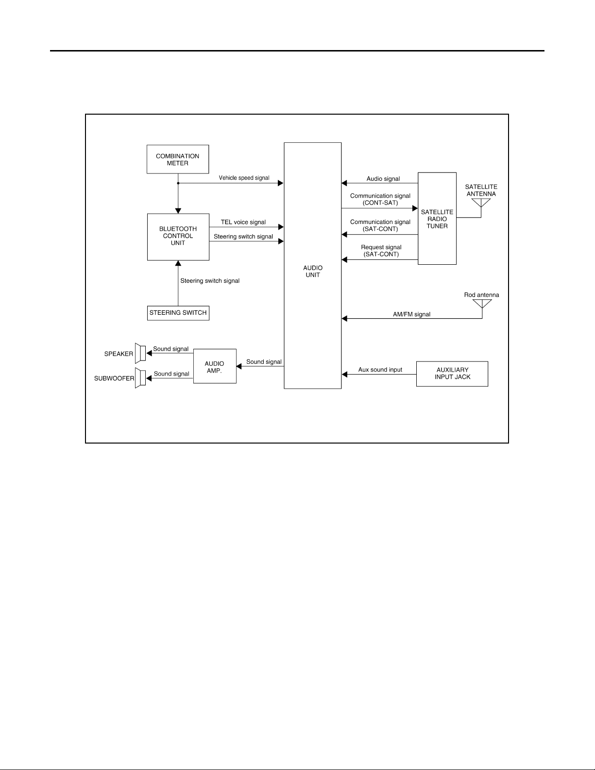
System Diagram INFOID:0000000004095411
@VMH@0700F
System Description INFOID:0000000004095412
AUDIO SYSTEM
The audio system consists of the following components
•Audio unit
•Audio amp.
•Rod antenna
•Steering wheel audio control switches
•Front door speakers
•Front tweeters
•Rear door speakers
•Rear tweeters
•Subwoofer
When the audio system is on, radio signals are received by the rod antenna. The audio unit then sends audio
signals to the audio amp. The audio amp. amplifies the audio signals before sending them to the front door
speakers, front tweeters, rear door speakers, rear door tweeters and the subwoofer.
Refer to Owner's Manual for audio system operating instructions.
SATELLITE RADIO SYSTEM
The satellite radio system consists of the following components
•Satellite antenna
•Satellite radio tuner
When the satellite radio system is on, radio signals are supplied to the satellite radio tuner from the satellite
antenna. The satellite radio tuner then sends audio signals to the audio unit.
Refer to Owner's Manual for satellite radio system operating instructions.
AV-36
Page 42
AUDIO SYSTEM
< FUNCTION DIAGNOSIS >
SPEED SENSITIVE VOLUME SYSTEM
Volume level of this system goes up and down automatically in proportion to the vehicle speed. The control
level can be selected by the customer. Refer to Owner's Manual for operating instructions.
[PREMIUM AUDIO]
A
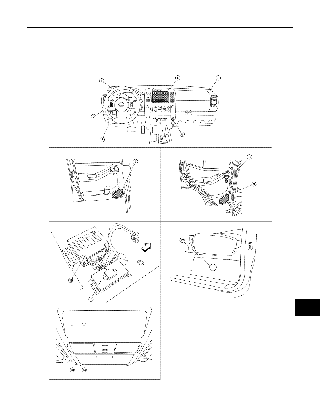
Component Parts Location INFOID:0000000004095413
B
C
D
E
F
G
H
I
AV
J
K
L
M
O
P
AV-37
@VMH@/683YY
Page 43

AUDIO SYSTEM
< FUNCTION DIAGNOSIS >
:FRONT
1. Front tweeter LH M110 2. Steering wheel audio control switch-es3. Satellite radio tuner M41, M129
4. Audio unit M42, M44, M45, M46 5. Front tweeter RH M112 6. Aux jack M85
7. Front door speaker
LH D12
RH D112
10. Audio amp B158, B159 (view under
passenger front seat)
13. Microphone R8 14. Bluetooth ON indicator R6
8. Rear door tweeter
LH D208
RH D308
11. Bl ueto oth con trol un it B 141, B14 2 12. Su bwoo fer B72 (un der dri ver’s se at)
9. Rear door speaker
LH D207
RH D307
[PREMIUM AUDIO]
Component Description INFOID:0000000004095414
Part name Description
Audio unit Controls audio system and satellite radio system functions
Audio amp.
Steering wheel a ud io control switches
Front door speakers
Front tweeters
Rear door speakers
Rear tweeters
Subwoofer
Satellite radio tuner
Satellite antenna Audio signal (satellite radio) is received and output to Audio unit.
Receives power (amp ON) and audio signals from Audio unit and outputs audio signals to each speaker.
•Audio operation can be operated
•Steering switch signal is output to Bluetooth control unit
•Start a voice recognition session
•Answer and end telephone calls
•Adjust the volume level
•Outputs audio signal from audio amp.
•Outputs high, mid and low range sounds
•Outputs audio signal from audio amp.
•Outputs high range sounds
•Outputs audio signal from audio amp.
•Outputs high, mid and low range sounds
•Outputs audio signal from audio amp.
•Outputs high range sounds
•Outputs audio signal from audio amp.
•Outputs low range sounds
•Receives radio signals from satellite antenna
•Sends audio signals to Audio unit
AV-38
Page 44
< FUNCTION DIAGNOSIS >
A
HANDS-FREE PHONE SYSTEM
[PREMIUM AUDIO]
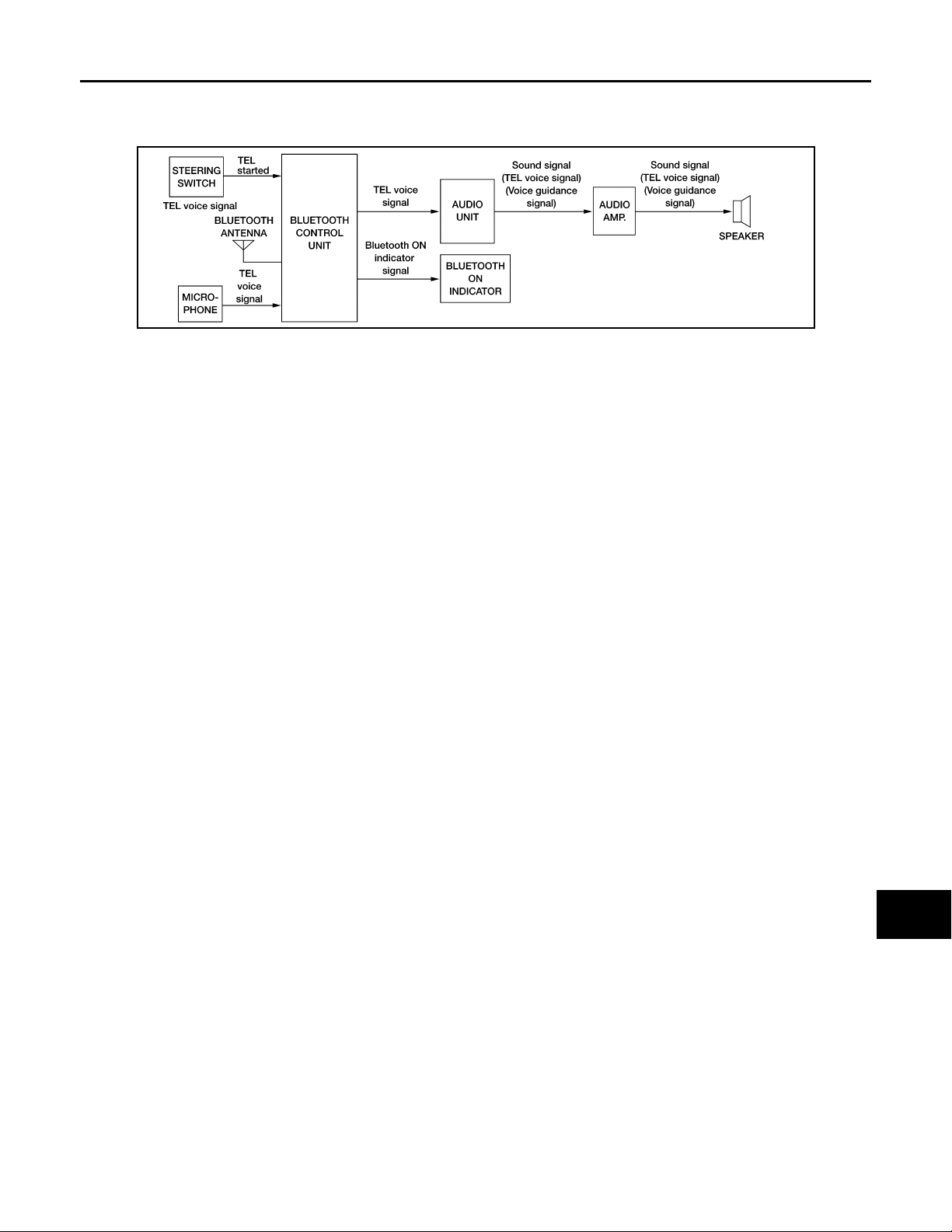
HANDS-FREE PHONE SYSTEM
System Diagram INFOID:0000000004095415
@VMH@070/ F
System Description INFOID:0000000004095416
Refer to the Owner's Manual for Bluetooth telephone system operating instructions.
NOTE:
Cellular telephones must have their wireless connection set up (paired) before using the Bluetooth telephone
system.
Bluetooth telephone system allows users who have a Bluetooth equipped cellular telephone to make a wireless connection between their cellular telephone and the Bluetooth control unit. Hands-free cellular telephone
calls can be sent and received. Some Bluetooth cellular telephones may not be recognized by the Bluetooth
control unit. When a cellular telephone or the Bluetooth control unit is replaced, the telephone must be paired
with the Bluetooth control unit. Different cellular telephones may have different pairing procedures. Refer to
the cellular telephone operating manual.
A
B
C
D
E
F
G
H
BLUETOOTH CONTROL UNIT
When the ignition switch is turned to ACC or ON, the Bluetooth control unit will power up. During power up, the
Bluetooth control unit is initialized and performs various self checks. Initialization may take up to 10 seconds.
During this time, the Bluetooth ON indicator will flash until initialization is complete. If a phone is present in the
vehicle and paired with the Bluetooth control unit, Nissan Voice Recognition will then become active. Bluetooth
telephone functions can be turned off using the Nissan Voice Recognition system.
STEERING WHEEL AUDIO CONTROL SWITCHES
When buttons on the steering wheel audio control switch are pushed, the resistance in steering wheel audio
control switch circuit changes depending on which button is pushed. The Bluetooth control unit uses this signal to perform various functions while navigating through the voice recognition system.
The following functions can be performed using the steering wheel audio control switch:
•Initiate Self Diagnosis of the Bluetooth telephone system
•Start a voice recognition session
•Answer and end telephone calls
•Adjust the volume of calls
MICROPHONE
The microphone is located in the roof console assembly. The microphone sends a signal to the Bluetooth control unit. The microphone can be actively tested during self-diagnosis.
AUDIO UNIT
The audio unit receives signals from the Bluetooth control unit and sends audio signals to the audio amp. then
on to the speakers.
BLUETOOTH ON INDICATOR
The Bluetooth ON indicator is located in the overhead console. The indicator will flash during power up whilethe Bluetooth control unit is initializing. This process may take up to 10 seconds. If a phone is present in
thevehicle and paired with the Bluetooth control unit, the indicator will remain on to indicate that the system
isready for voice commands. The indicator flashes during self-diagnosis.
I
J
K
L
M
AV
O
P
AV-39
Page 45
< FUNCTION DIAGNOSIS >
HANDS-FREE PHONE SYSTEM
[PREMIUM AUDIO]
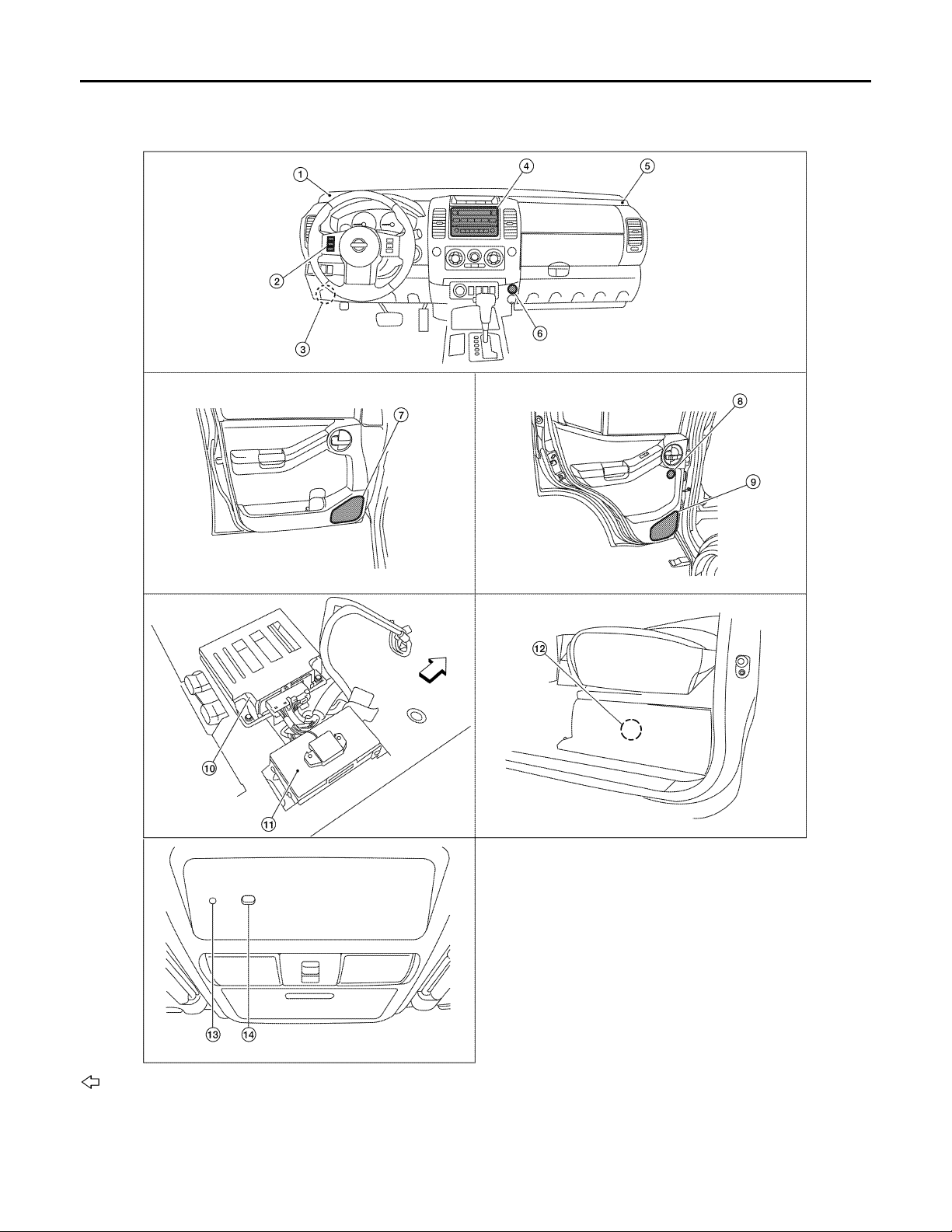
Component Parts Location
INFOID:0000000004095417
@VMH@/683YY
:FRONT
1. Front tweeter LH M110 2. Steering wheel audio control switch-es3. Satellite radio tuner M41, M129
4. Audio unit M42, M44, M45, M46 5. Front tweeter RH M112 6. Aux jack M85
AV-40
Page 46
HANDS-FREE PHONE SYSTEM
< FUNCTION DIAGNOSIS >
7. Front door speaker
LH D12
RH D112
10. Audio amp B158, B159 (view under
passenger front seat)
13. Microphone R8 14. Bluetooth ON indicator R6
8. Rear door tweeter
LH D208
RH D308
11. Bl ueto oth con trol un it B 141 , B1 42 12. Sub woo fer B72 (un der dri ver’s se at)
[PREMIUM AUDIO]
9. Rear door speaker
LH D207
RH D307
A
B
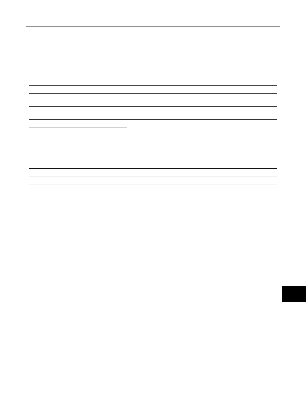
Component Description INFOID:0000000004095418
Part name Description
Audio unit
Audio amp.
Front door speaker
Front tweeter
Steering wheel aud io control switches
Microphone Sends voice signals to Bluetooth control unit
Bluetooth control unit Controls hands-free phone functions
Bluetooth antenna Sends telephone voice signal to Bluetooth control unit
Bluetooth ON indicator Controlled by the Bluetooth control unit
•Receives telephone voice signal from Bluetooth control unit
•Sends telephone voice and voice guidance signals to the speakers
•Recieves audio signals from the audio unit
•Outputs amplified audio signals to the speakers.
Receives telephone voice and voice guidance signals from the audio amp.
•Start a voice recognition session
•Answer and end telephone calls
•Adjust the volume level
C
D
E
F
G
H
I
J
AV
K
L
M
O
P
AV-41
Page 47
DIAGNOSIS SYSTEM (AUDIO UNIT)
< FUNCTION DIAGNOSIS >
[PREMIUM AUDIO]
DIAGNOSIS SYSTEM (AUDIO UNIT)
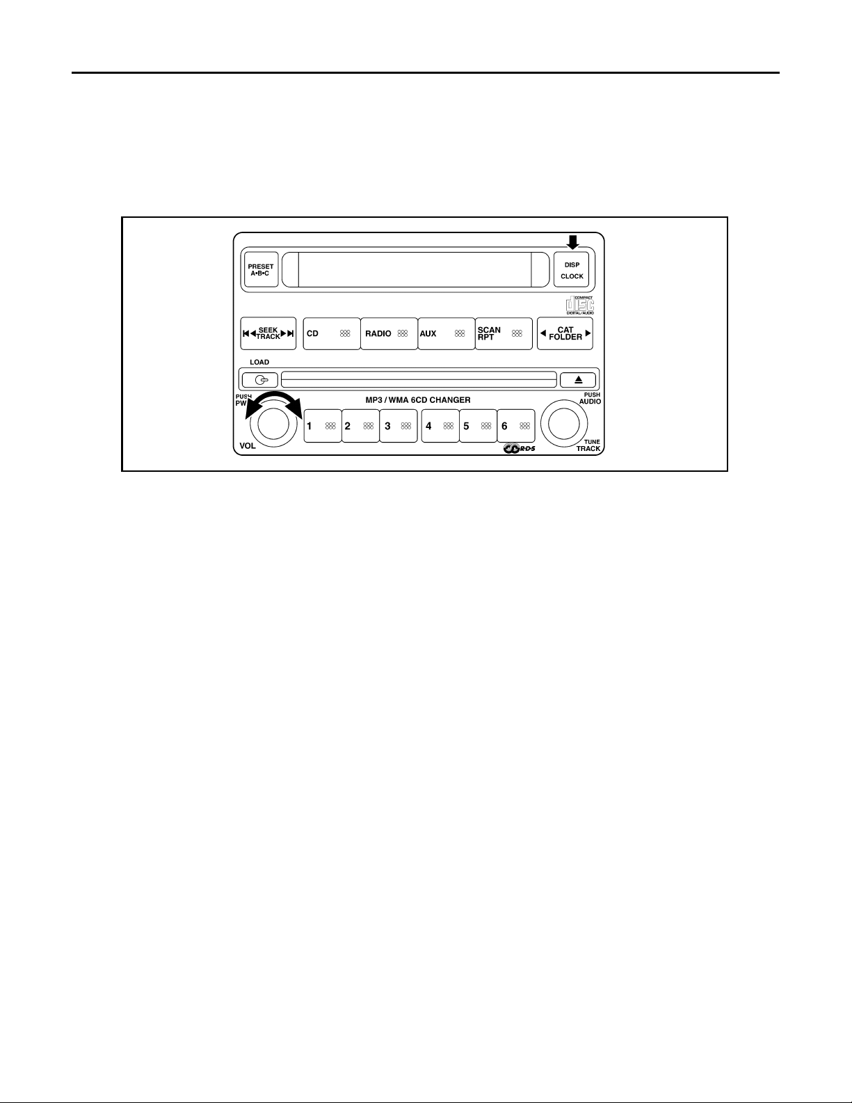
Component Function Check INFOID:0000000004095419
STARTING THE SELF-DIAGNOSIS MODE
1. Turn ignition switch from OFF to ACC.
2. Press and hold the “DISP/CLOCK” switch and turn the volume control dial clockwise or counterclockwise
for 30 clicks or more.
VJH@4708D
Then the self-diagnosis operates. A single beep indicates self-diagnosis mode is active.
3. Initially, all display segments will be illuminated.
4. Press each switch. When each switch is pressed, its name and communication code will be displayed
NOTE:
CD player LOAD and EJECT buttons are not included in this test and will not change the display when
pressed.
DIAGNOSIS FUNCTION
•It can check for continuity of the switches by sounding the beep when each audio unit switch and steering
switch is pressed.
•It can check for continuity of harness between audio unit and steering switch.
EXITING THE SELF-DIAGNOSIS MODE
Turn ignition switch OFF. Then the self-diagnosis ends.
AV-42
Page 48
DIAGNOSIS SYSTEM (BLUETOOTH CONTROL UNIT)
< FUNCTION DIAGNOSIS >
[PREMIUM AUDIO]
DIAGNOSIS SYSTEM (BLUETOOTH CONTROL UNIT)
Diagnosis Description INFOID:0000000004095420
The Bluetooth control unit has two diagnostic checks. The first diagnostic check is performed automatically
every ignition cycle during control unit initialization. The second diagnostic check is performed by the technician using the steering wheel audio control switches prior to trouble diagnosis.
BLUETOOTH CONTROL UNIT INITIALIZATION CHECKS
•Internal control unit failure
•Bluetooth antenna connection open or shorted
•Steering wheel audio control switches [SEND( )/END( )] stuck closed
•Vehicle speed pulse count
• Microphone connection test (with playback to operator)
•Bluetooth inquiry check
OPERATION PROCEDURE
1. Turn ignition switch to ACC or ON.
2. Wait for the Bluetooth system to complete initialization. This may take up to 10 seconds.
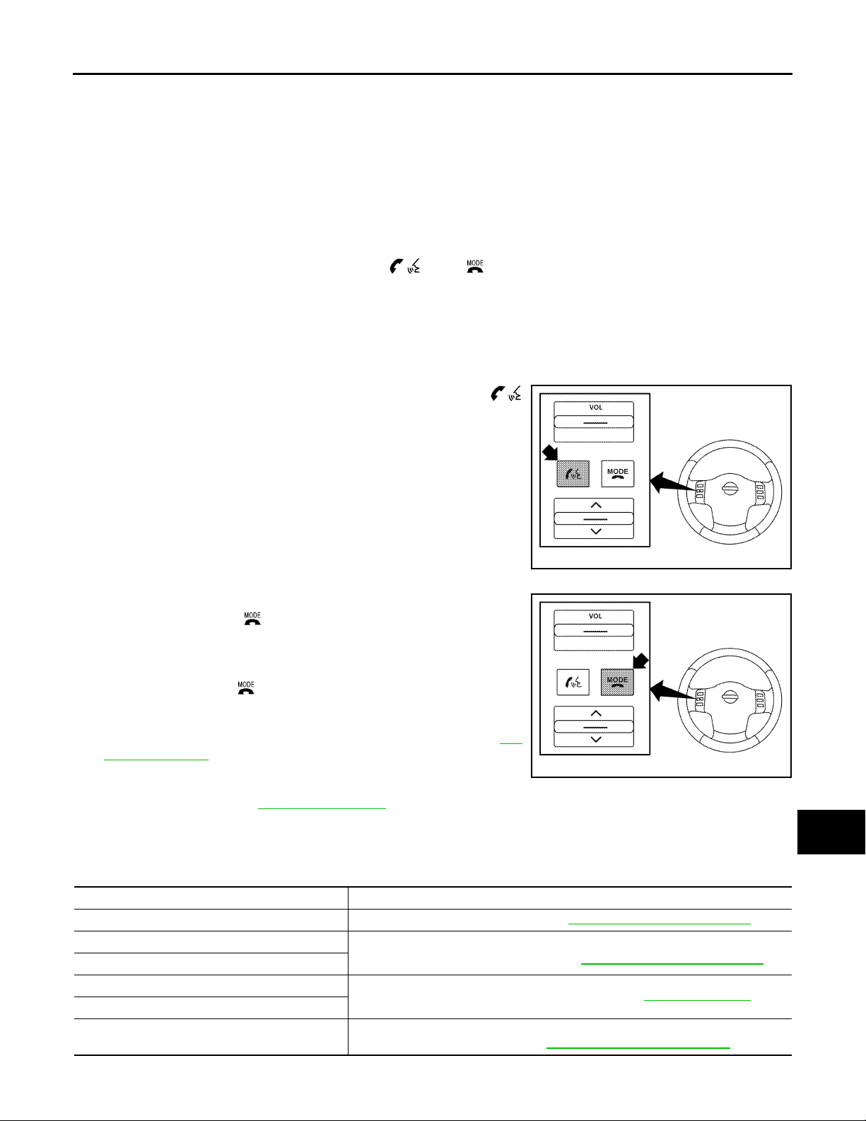
3. Press and hold the steering wheel audio control switch
button for at least 5 seconds. The Bluetooth system will begin to
play a verbal prompt.
A
B
C
D
E
F
G
H
@KMH@/337FA
4. While the prompt is playing, press and hold the steering wheel
audio control switch button until you hear the “Diagnostics
mode” prompt. The Bluetooth system will sound a 5 second
beep.
5. While the beep is sounding, press and hold the steering wheel
audio control switch button again until you hear prompts.
6. The Bluetooth system has now entered into the diagnostic
mode. Results of the diagnostic checks will be verbalized to the
technician and the Bluetooth ON indicator will flash. Refer to AV-
43, "Work Flow".
7. After the failure records are reported, an interactive microphone
@KMH@/338FA
test will be performed. Follow the voice prompt. If the microphone test fails refer to AV-43 , "
Work Flow".
8. Self-diagnosis mode is complete when the voice prompt says “All diagnostic functions completed”.
Work Flow INFOID:0000000004095421
Failure Message Action
“Internal failure” Replace Bluetooth control unit. Refer to AV-111, "
“Bluetooth antenna open”
“Bluetooth antenna shorted”
“Phone/Send for Hands Free System is stuck”
“Phone/End for the Hands Free System is stuck”
“Microphone test” (failed interactive test)
1. Inspect harness connection.
2. Replace Bluetooth antenna. Refer to AV-111, "Removal and Installation".
Check steering wheel audio control switches. Refer to AV-65, "
1. Inspect harness between Bluetooth control unit and microphone.
2. Replace microphone. Refer to AV-113 , "
Removal and Installation".
Description".
Removal and Installation".
I
J
K
L
M
AV
O
P
AV-43
Page 49
POWER SUPPLY AND GROUND CIRCUIT
< COMPONENT DIAGNOSIS >
[PREMIUM AUDIO]
COMPONENT DIAGNOSIS
POWER SUPPLY AND GROUND CIRCUIT
AUDIO UNIT
AUDIO UNIT : Diagnosis Procedure INFOID:0000000004095422
1.CHECK FUSES
Check that the following fuses of the audio unit are not are not blown.
Unit Terminals Signal name Fuse No.
Audio unit
Are the fuses OK?
YES >> GO TO 2
NO >> If fuse is blown, be sure to eliminate cause of malfunction before installing new fuse.
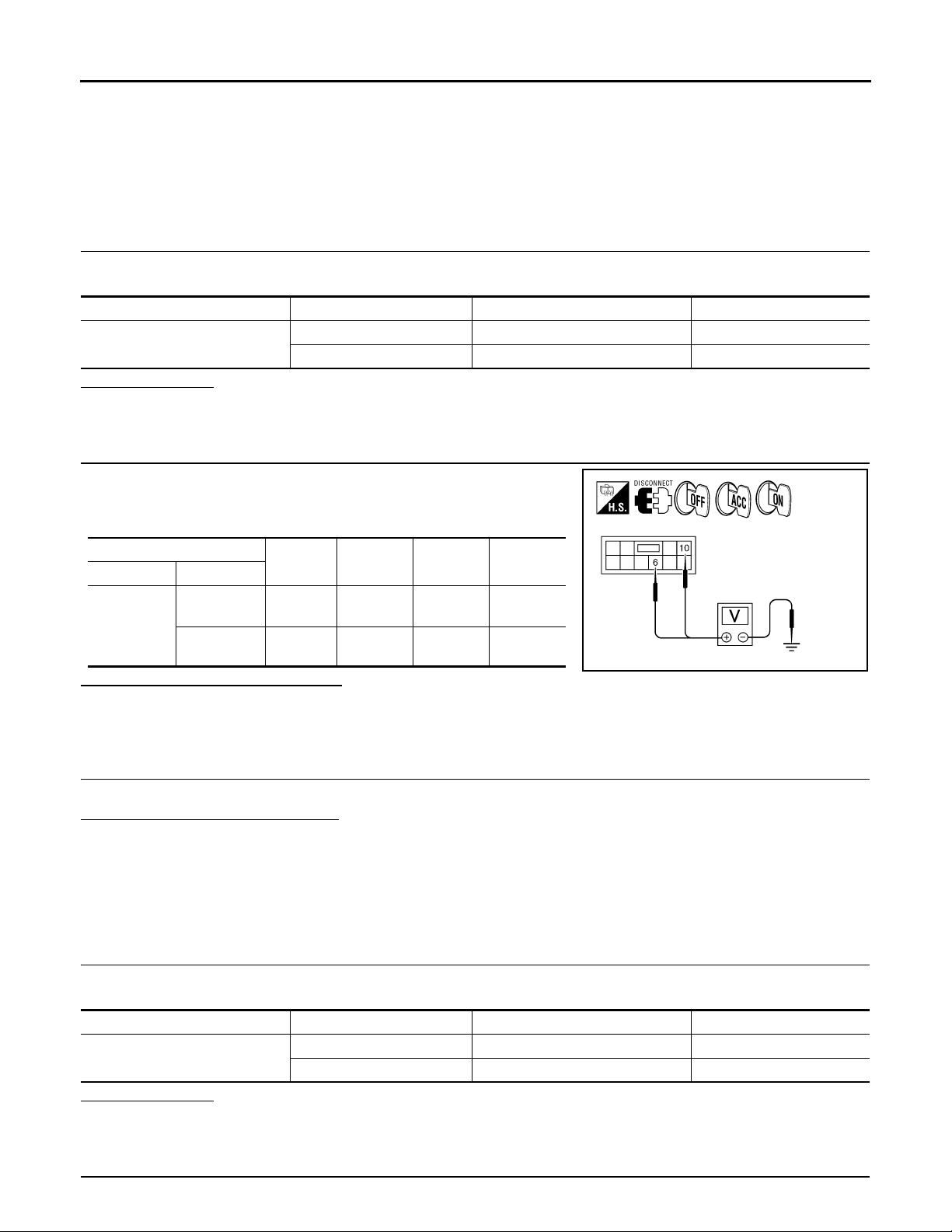
2.POWER SUPPLY CIRCUIT CHECK
1. Disconnect audio unit connector M46.
2. Check voltage between the audio unit connector M46 and
ground.
6Battery power 29
10 Ignition switch ACC or ON 4
(+)
Connector Terminal
6Ground0V
M46
10 Ground
Are the voltage results as specified?
YES >> GO TO 3
NO >> • Check connector housing for disconnected or loose terminals.
•Repair harness or connector.
(-) OFF ACC ON
Battery
voltage
Battery
voltage
Battery
voltage
Battery
voltage
Battery
voltage
@KMH@/584FA
3.GROUND CIRCUIT CHECK
Inspect audio unit case ground.
Does case ground pass inspection?
YES >> Inspection End.
NO >> Repair audio unit case ground.
SATELLITE RADIO TUNER
SATELLITE RADIO TUNER : Diagnosis Procedure INFOID:0000000004095423
1.CHECK FUSES
Check that the following fuses of the satellite radio tuner (factory installed) are not blown.
Unit Terminals Signal name Fuse No.
Satellite radio tuner (factory installed)
Are the fuses OK?
YES >> GO TO 2
NO >> If fuse is blown, be sure to eliminate cause of malfunction before installing new fuse.
32 Battery power 17
36 Ignition switch ACC or ON 4
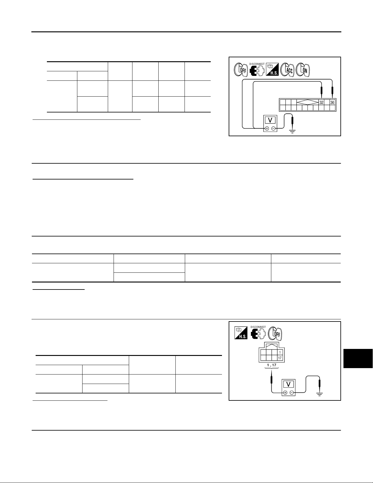
2.POWER SUPPLY CIRCUIT CHECK
AV-44
Page 50
POWER SUPPLY AND GROUND CIRCUIT
< COMPONENT DIAGNOSIS >
1. Turn ignition switch OFF.
2. Disconnect satellite radio tuner (factory installed) connector M41.
3. Check voltage between the satellite radio tuner (factory installed) and ground.
[PREMIUM AUDIO]
A
(+)
Connector Terminal
32
M41
36 0V
(-) OFF ACC ON
Ground
Battery
voltage
Battery
voltage
Battery
voltage
Battery
voltage
Battery
voltage
Are the voltage readings as specified?
YES >> GO TO 3
NO >> • Check connector housings for disconnected or loose
VJH@3428 D
terminals.
•Repair harness or connector.
3.GROUND CIRCUIT CHECK
Inspect satellite radio tuner (factory installed) case ground.
Does case ground pass inspection?
YES >> Inspection End.
NO >> Repair satellite radio tuner (factory installed) case ground.
AUDIO AMP
AUDIO AMP : Diagnosis Procedure INFOID:0000000004095424
1.CHECK FUSE
Check that the audio amp. fuses are not blown.
B
C
D
E
F
G
H
I
Unit Terminal Signal name Fuse No.
Audio amp.
17
1
Battery power 17
Are the fuses OK?
YES >> GO TO 2
NO >> Be sure to eliminate cause of malfunction before installing new fuse.
2.CHECK POWER SUPPLY CIRCUIT
1. Turn ignition switch OFF.
2. Disconnect audio amp. connector.
3. Check voltage between audio amp. harness connector B158
and ground.
(+)
Connector Terminal
B158
1
17
(-) Voltage (approx.)
Ground Battery voltage
Is battery voltage present?
YES >> GO TO 3
NO >> Check harness between audio amp. and fuse.
3.CHECK GROUND CIRCUIT
J
K
L
M
AV
O
@KMH@/643FA
P
AV-45
Page 51
POWER SUPPLY AND GROUND CIRCUIT
< COMPONENT DIAGNOSIS >
1. Turn ignition switch OFF.
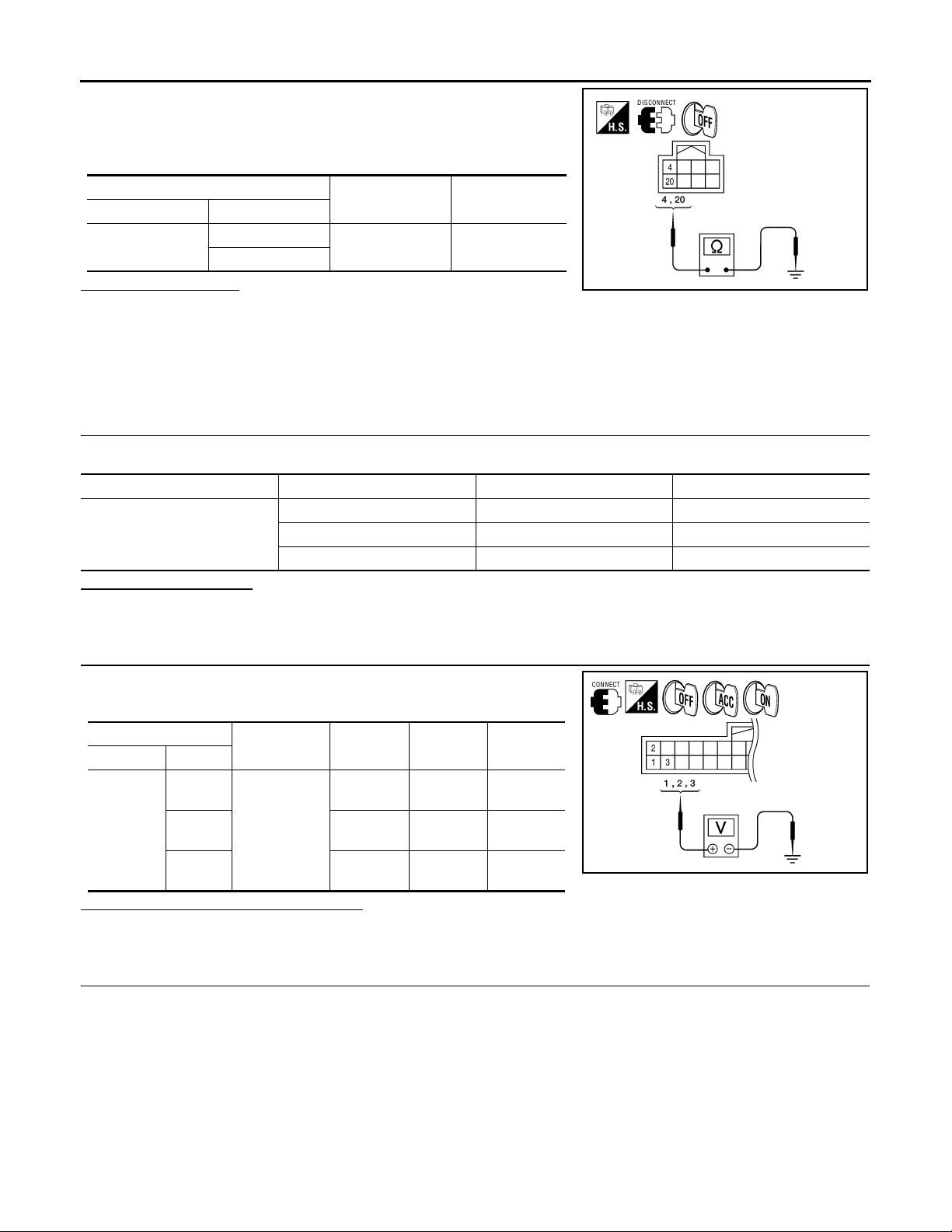
2. Disconnect audio amp. connector.
3. Check continuity between audio amp. harness connector B158
and ground.
[PREMIUM AUDIO]
(+)
Connector Terminal
B158
Does continuity exist?
4
20
(-) Continuity
Ground Yes
@KMH@/644FA
YES >> Inspection End.
NO >> Repair harness or connector.
BLUETOOTH CONTROL UNIT
BLUETOOTH CONTROL UNIT : Diagnosis Procedure INFOID:0000000004095425
1.CHECK FUSE
Check that the following fuses for the Bluetooth control unit are not blown.
Unit Terminal Signal name Fuse No.
1Battery power 29
Bluetooth control unit
2Ignition switch ACC or ON 4
3Ignition switch ON or START 12
Is inspection result OK?
YES >> GO TO 2.
NO >> Be sure to eliminate cause of malfunction before installing new fuse.
2.CHECK POWER SUPPLY CIRCUIT
Check voltage between Bluetooth control unit harness connector
B141 and ground.
(+)
Connector Terminal
1
B141
20V
30V
(-) OFF ON ACC
Battery
voltage
Ground
Battery
voltage
Battery
voltage
Battery
voltage
Battery
voltage
Battery
voltage
0V
Is battery voltage present as specified?
YES >> GO TO 3.
NO >> Check harness between Bluetooth control unit and fuse.
3.CHECK GROUND CIRCUIT
@KMH@/212FA
AV-46
Page 52
POWER SUPPLY AND GROUND CIRCUIT
A
< COMPONENT DIAGNOSIS >
1. Turn ignition switch OFF.
2. Disconnect Bluetooth control unit connector.
3. Check continuity between Bluetooth control unit harness connector B141 and ground.
[PREMIUM AUDIO]
A
Connector Terminal — Continuity
4
B141
24
Are continuity results as specified?
Ground Yes21
@VMH@/7// F
YES >> Inspection End.
NO >> Repair harness or connector.
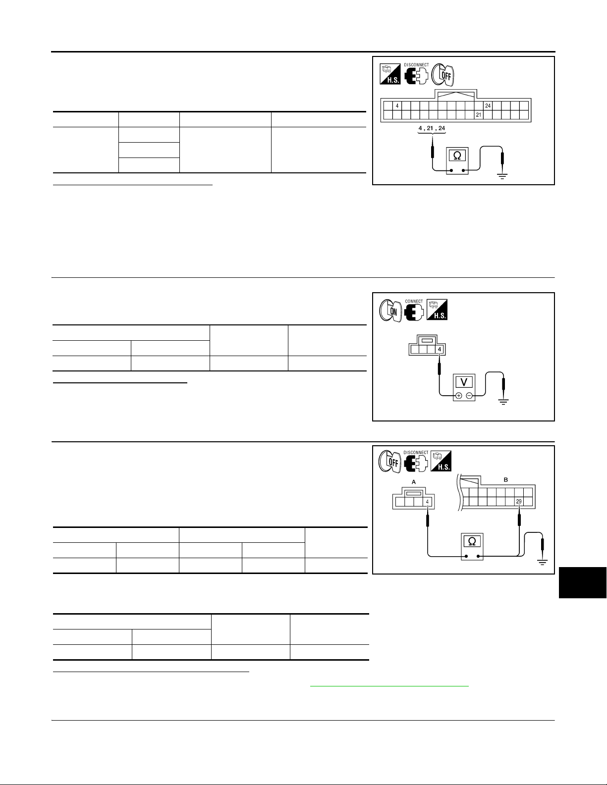
MICROPHONE
MICROPHONE : Diagnosis Procedure INFOID:0000000004095426
1.CHECK POWER SUPPLY CIRCUIT (MICROPHONE SIDE)
1. Turn ignition switch ON.
2. Check voltage between microphone harness connector R8 terminal 4 and ground.
(+)
Connector Terminal
R8 4 Ground 5V
(-)
Valu e (A ppro x.)
Is approximately 5V present?
YES >> GO TO 3
NO >> GO TO 2
VJH@4685 D
2.CHECK POWER SUPPLY CIRCUIT (CONTINUITY)
B
C
D
E
F
G
H
I
J
1. Turn ignition switch OFF.
2. Disconnect microphone and Bluetooth control unit harness connectors.
3. Check continuity between microphone harness connector R8
(A) terminal 4 and Bluetooth control unit harness connector
B141 (B) terminal 29.
AB
Connector Terminal Connector Terminal
R8 4 B141 29 Yes
Continuity
4. Check continuity between microphone harness connector R8
(A) terminal 4 and ground.
A
Connector Terminal
R8 4 Ground No
—Continuity
Are the continuity test results as specified?
YES >> Replace the Bluetooth control unit. Refer to AV-111, "Removal and Installation".
NO >> Repair harness or connector.
3.CHECK GROUND CIRCUIT
K
L
M
@KMH@/21/FA
AV
O
P
AV-47
Page 53
POWER SUPPLY AND GROUND CIRCUIT
< COMPONENT DIAGNOSIS >
1. Turn ignition switch OFF.
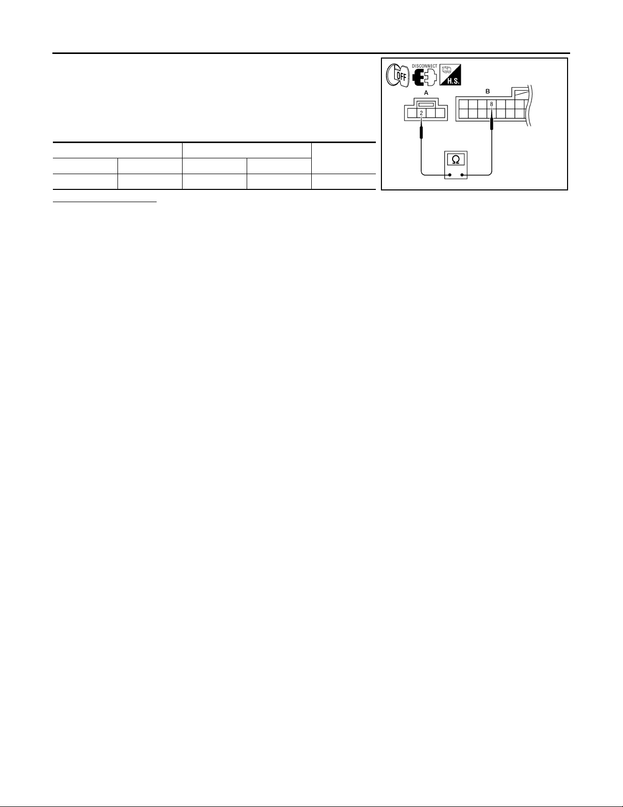
2. Disconnect microphone harness connector R8 and Bluetooth
control unit harness connector B141.
3. Check continuity between microphone harness connector R8
(A) terminal 2 and Bluetooth control unit harness connector
B141 (B) terminal 8.
[PREMIUM AUDIO]
AB
Connector Terminal Connector Terminal
R8 2 B141 8 Yes
Does continuity exist?
YES >> Inspection End.
NO >> Repair harness or connector.
Continuity
@KMH@/211FA
AV-48
Page 54
< COMPONENT DIAGNOSIS >
FRONT DOOR SPEAKER
[PREMIUM AUDIO]
FRONT DOOR SPEAKER
Description INFOID:0000000004095427
The audio unit sends audio signals to the audio amp. The audio amp. amplifies the audio signals before sending them to the front door speakers using the audio signal circuits.
Diagnosis Procedure INFOID:0000000004095428
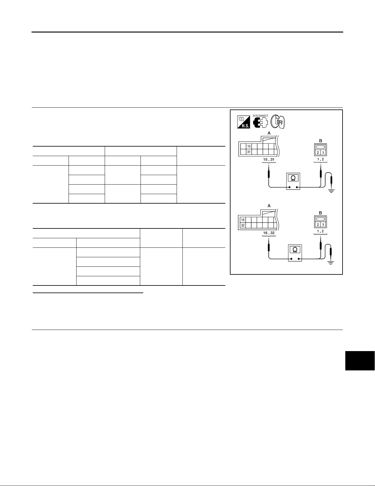
1.SPEAKER HARNESS CHECK
1. Disconnect audio amp. connector B159 and suspect speaker
connector.
2. Check continuity between audio amp. harness connector B159
(A) and suspect speaker harness connector (B).
A B
Connector Terminal Connector Terminal
B159
15
31 2
16
32 2
D12
D112
1
1
3. Check continuity between audio amp. harness connector B159
(A) and ground.
Continuity
Yes
A
B
C
D
E
F
G
H
A
Connector Terminal
15
B159
31
16
32
—Continuity
Ground No
Are continuity test results as specified?
YES >> GO TO 2
NO >> • Check connector housings for disconnected or loose terminals.
•Repair harness or connector.
2.FRONT DOOR SPEAKER SIGNAL CHECK
I
J
@KMH@/607FA
K
L
M
AV
O
P
AV-49
Page 55
FRONT DOOR SPEAKER
< COMPONENT DIAGNOSIS >
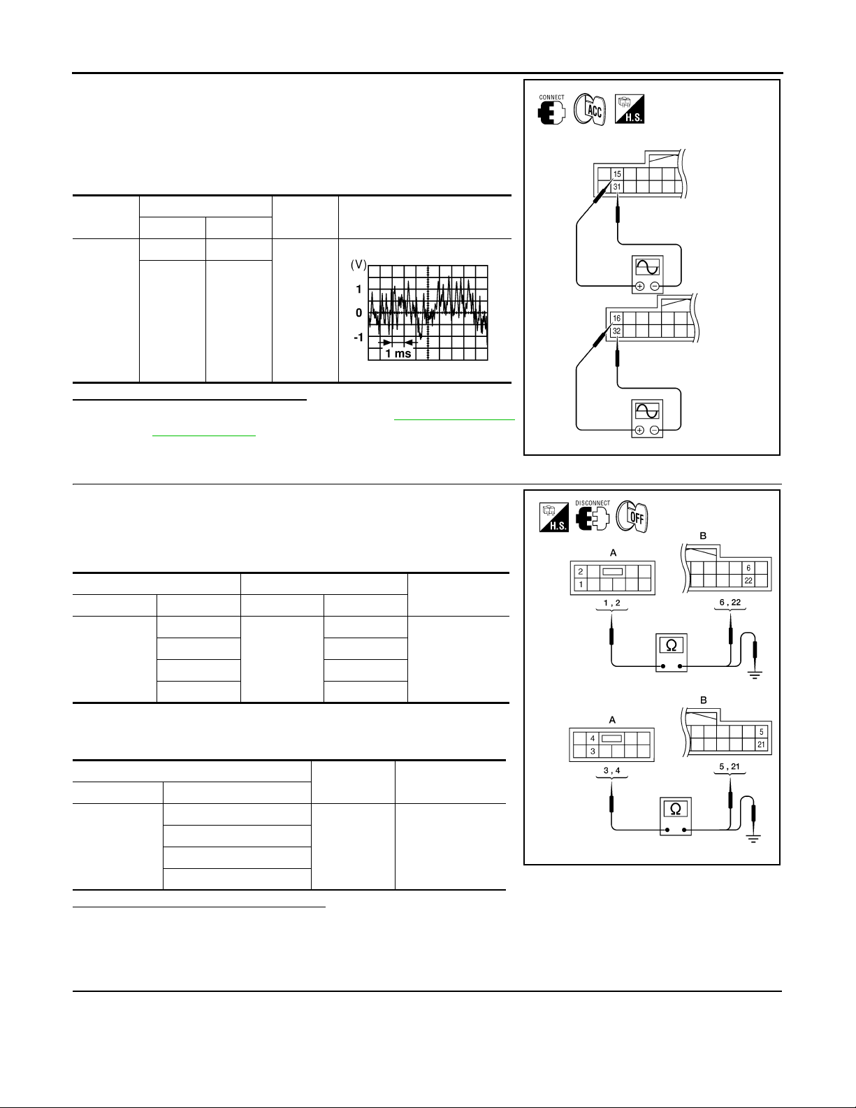
1. Connect audio amp. connector B159 and suspect speaker connector.
2. Turn ignition switch to ACC.
3. Push “POWER” switch.
4. Check the signal between audio amp. harness connector B159
terminals with CONSULT-III or oscilloscope.
[PREMIUM AUDIO]
Connec-
tor
B159
Te rm i na l
(+) (-)
15 31
16 32
Condition
Receive
audio signal
Reference
signal
RJ H@/066D
Is audio signal voltage as specified?
YES >> Replace suspect speaker. Refer to AV-106, "Removal
and Installation".
NO >> GO TO 3
3.PRE-AMP HARNESS CHECK
1. Disconnect audio unit connector M46 and audio amp. connector
B159.
2. Check continuity between audio unit harness connector M46 (A)
and audio amp. harness connector B159 (B).
AB
Connector Terminal Connector Terminal
M46
1
222
35
421
B159
6
3. Check continuity between audio unit harness connector M46 (A)
and ground.
Continuity
Yes
@KMH@/608FA
A
Connector Terminal
1
M46
2
3
4
—Continuity
Ground No
Are continuity test results as specified?
YES >> GO TO 4
NO >> • Check connector housings for disconnected or loose terminals.
•Repair harness or connector.
4.PRE-AMP SIGNAL CHECK
AV-50
@KMH@/61/FA
Page 56
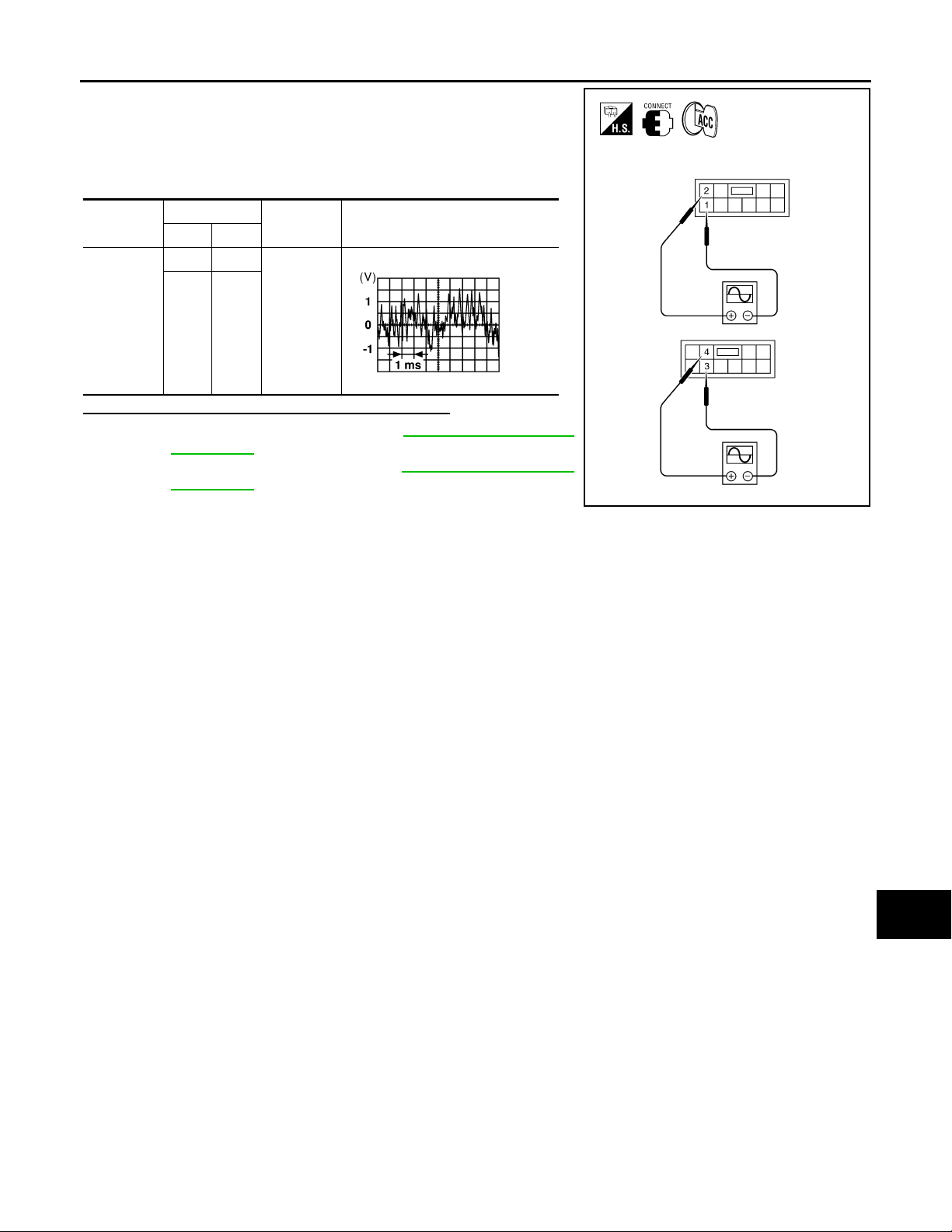
FRONT DOOR SPEAKER
< COMPONENT DIAGNOSIS >
1. Connect audio unit connector and audio amp. connector.
2. Turn ignition switch ACC.
3. Push “POWER” switch.
4. Check the signal between audio unit harness connector M46
terminals with CONSULT-III or oscilloscope.
[PREMIUM AUDIO]
A
B
Connector
M46
Te rm inals
(+) (-)
21
43
Condition
Receive
audio signal
Reference
signal
RJ H@/066D
Are the audio signal voltage readings as specified?
YES >> Replace audio amp. Refer to AV-104, "Removal and
Installation".
NO >> Replace audio unit. Refer to AV-103, "
Removal and
Installation".
C
D
E
F
G
@VMH@07/ 2YY
H
I
AV
J
K
L
M
O
P
AV-51
Page 57
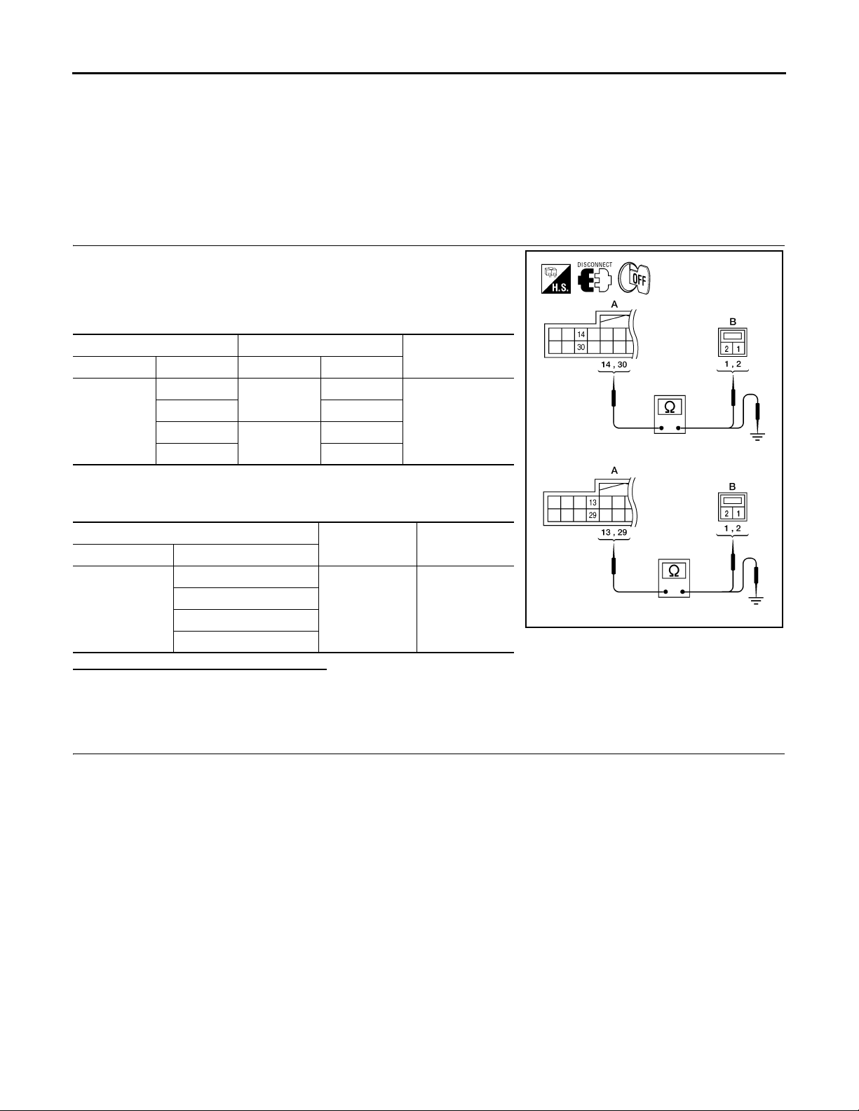
FRONT TWEETER
< COMPONENT DIAGNOSIS >
[PREMIUM AUDIO]
FRONT TWEETER
Description INFOID:0000000004095429
The audio unit sends audio signals to the audio amp. The audio amp. amplifies the audio signals before sending them to the tweeters using the audio signal circuits.
Diagnosis Procedure INFOID:0000000004095430
1.HARNESS CHECK
1. Disconnect audio amp. connector B159 and suspect tweeter
connector.
2. Check continuity between audio amp. harness connector B159
(A) and suspect tweeter harness connector (B).
A B
Connector Terminal Connector Terminal
B159
14
30 2
13
29 2
M110
M112
1
1
Continuity
Yes
3. Check continuity between audio amp. harness connector B159
(A) and ground.
A
Connector Terminal
14
B159
30
13
29
—Continuity
Ground No
Are continuity test results as specified?
YES >> GO TO 2
NO >> • Check connector housings for disconnected or loose terminals.
•Repair harness or connector.
2.FRONT TWEETER SIGNAL CHECK
@KMH@/611FA
AV-52
Page 58
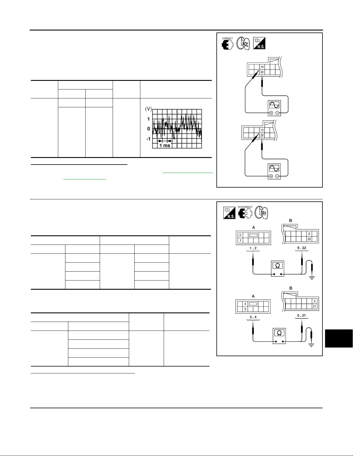
FRONT TWEETER
< COMPONENT DIAGNOSIS >
1. Connect audio amp. connector B159 and suspect tweeter connector.
2. Turn ignition switch to ACC.
3. Push “POWER” switch.
4. Check the signal between audio amp. harness connector B159
terminals with CONSULT-III or oscilloscope.
[PREMIUM AUDIO]
A
B
Connec-
tor
B159
Te rm in al
(+) (-)
14 30
13 29
Condition
Receive
audio signal
Reference
signal
RJ H@/066D
Is audio signal voltage as specified?
YES >> Replace suspect tweeter. Refer to AV-105 , "Removal
and Installation".
NO >> GO TO 3
3.PRE-AMP HARNESS CHECK
1. Disconnect audio unit connector M46 and audio amp. connector
B159.
2. Check continuity between audio unit harness connector M46 (A)
and audio amp. harness connector B159 (B).
AB
Connector Terminal Connector Terminal
M46
1
222
35
421
B159
6
3. Check continuity between audio unit harness connector M46 (A)
and ground.
Continuity
Yes
C
D
E
F
G
@KMH@/612FA
H
I
J
K
L
A
Connector Terminal
1
M46
2
3
4
—Continuity
Ground No
Are continuity test results as specified?
YES >> GO TO 4
NO >> • Check connector housings for disconnected or loose terminals.
•Repair harness or connector.
4.PRE-AMP SIGNAL CHECK
AV-53
M
AV
@KMH@/61/FA
O
P
Page 59
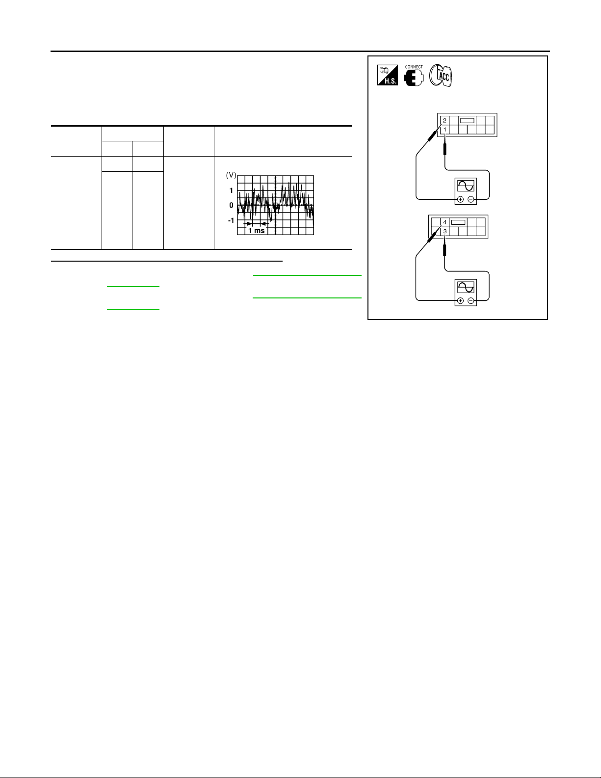
FRONT TWEETER
< COMPONENT DIAGNOSIS >
1. Connect audio unit connector and audio amp. connector.
2. Turn ignition switch ACC.
3. Push “POWER” switch.
4. Check the signal between audio unit harness connector M46
terminals with CONSULT-III or oscilloscope.
[PREMIUM AUDIO]
Connector
M46
Te rm i na ls
(+) (-)
21
43
Condition
Receive
audio signal
Reference
signal
RJ H@/066D
Are the audio signal voltage readings as specified?
YES >> Replace audio amp. Refer to AV-104, "Removal and
Installation".
NO >> Replace audio unit. Refer to AV-103, "
Removal and
Installation".
@VMH@07/ 2YY
AV-54
Page 60
< COMPONENT DIAGNOSIS >
REAR DOOR SPEAKER
[PREMIUM AUDIO]
REAR DOOR SPEAKER
Description INFOID:0000000004095431
The audio unit sends audio signals to the audio amp. The audio amp. amplifies the audio signals before sending them to the rear door speakers using the audio signal circuits.
Diagnosis Procedure INFOID:0000000004095432
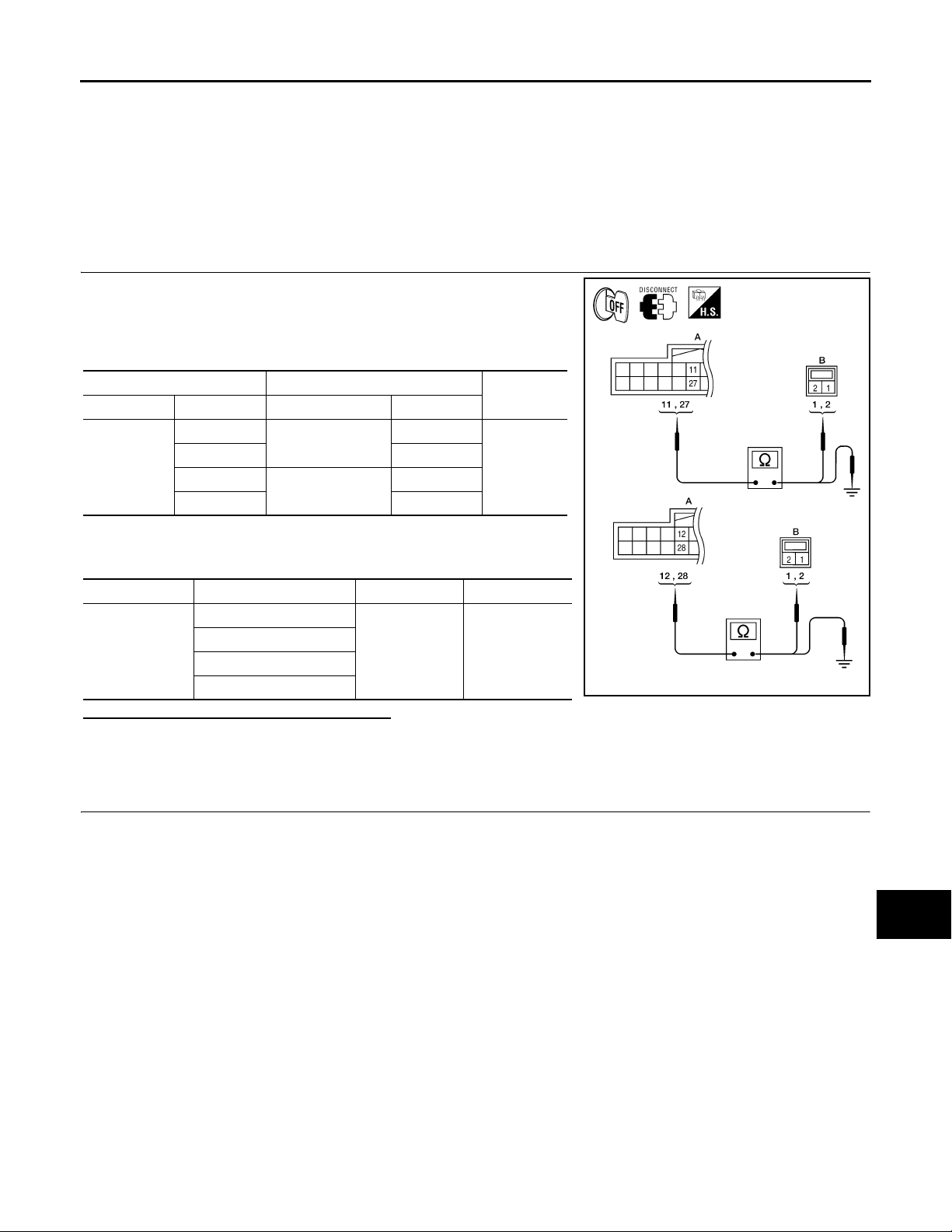
1.SPEAKER HARNESS CHECK
1. Disconnect audio amp. connectors B159 and suspect speaker
connector.
2. Check continuity between audio amp. harness connectors B159
(A) and suspect speaker harness connector (B).
AB
Connector Terminal Connector Terminal
B159
11
27 2
12
28 2
D207
D307
1
1
3. Check continuity between audio amp. harness connectors B159
(A) and ground.
Continuity
Yes
A
B
C
D
E
F
G
H
Connector Terminal - Continuity
11
B159
27
12
28
Ground No
Are the continuity test results as specified?
YES >> GO TO 2
NO >> • Check connector housings for disconnected or loose terminals.
•Repair harness or connector.
2.SPEAKER SIGNAL CHECK
I
J
@KMH@/615FA
K
L
M
AV
O
P
AV-55
Page 61
REAR DOOR SPEAKER
< COMPONENT DIAGNOSIS >
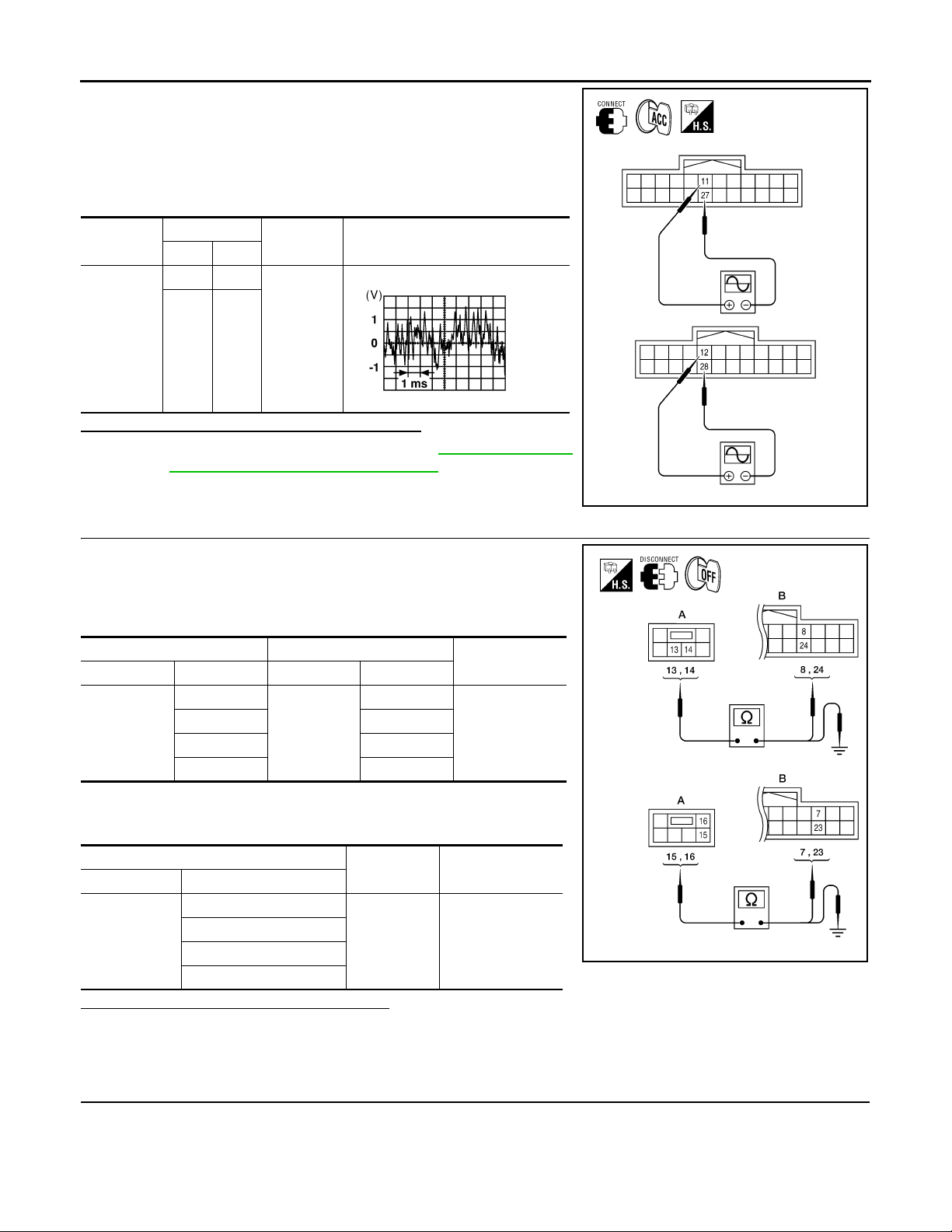
1. Connect audio amp. connectors and suspect speaker connector.
2. Turn ignition switch to ACC.
3. Push “POWER” switch.
4. Check the signal between audio amp. harness connectors B159
terminals with CONSULT-III or oscilloscope.
[PREMIUM AUDIO]
Connector
B159
Te rm i na ls
(+) (-)
11 27
12 28
Condition
Receive
audio signal
Reference
signal
RJ H@/066D
Are audio signal voltage readings as specified?
YES >> Replace suspect speaker. Refer to AV-107, "Removal
and Installation - Rear Door Speaker".
NO >> GO TO 3
3.PRE-AMP HARNESS CHECK
1. Disconnect audio unit connector M44 and audio amp. connector
B159.
2. Check continuity between audio unit harness connector M44 (A)
and audio amp. harness connector B159 (B).
AB
Connector Terminal Connector Terminal
M44
13
14 24
15 7
16 23
B159
8
3. Check continuity between audio unit harness connector M44 (A)
and ground.
Continuity
Yes
@KMH@/616FA
A
Connector Terminal
13
M44
14
15
16
—Continuity
Ground No
Are the continuity test results as specified?
YES >> GO TO 4
NO >> • Check connector housings for disconnected or loose terminals.
•Repair harness or connector.
4.PRE-AMP SIGNAL CHECK
AV-56
@KMH@/618FA
Page 62
REAR DOOR SPEAKER
< COMPONENT DIAGNOSIS >
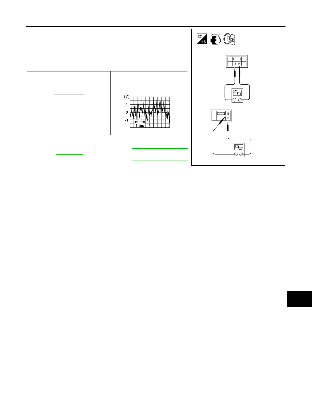
1. Connect audio unit connector M44 and audio amp. connector
B159.
2. Turn ignition switch to ACC.
3. Push “POWER” switch.
4. Check the signal between audio unit harness connector M44
terminals with CONSULT-III or oscilloscope.
[PREMIUM AUDIO]
A
B
Connector
M44
Te rm i na ls
(+) (-)
14 13
16 15
Condition
Receive
audio signal
Reference
signal
RJ H@/066D
Is the audio signal voltage reading as specified?
YES >> Replace audio amp. Refer to AV-104, "Removal and
Installation".
NO >> Replace audio unit. Refer to AV-103, "
Removal and
Installation".
C
D
E
F
G
@VMH@07/ 3YY
H
I
J
AV
K
L
M
O
P
AV-57
Page 63
REAR DOOR TWEETER
< COMPONENT DIAGNOSIS >
[PREMIUM AUDIO]
REAR DOOR TWEETER
Description INFOID:0000000004095433
The audio unit sends audio signals to the audio amp. The audio amp. amplifies the audio signals before sending them to the rear door tweeters using the audio signal circuits.
Diagnosis Procedure INFOID:0000000004095434
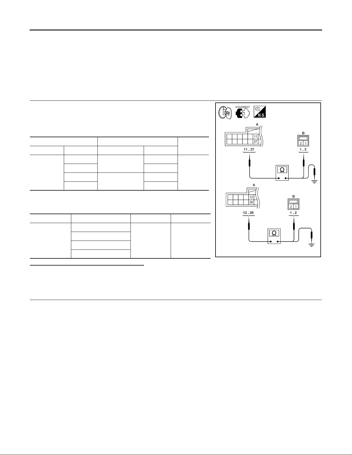
1.SPEAKER HARNESS CHECK
1. Disconnect audio amp. connectors B159 and suspect speaker
connector.
2. Check continuity between audio amp. harness connectors B159
(A) and suspect speaker harness connector (B).
AB
Connector Terminal Connector Terminal
B159
11
27 2
12
28 2
D208
D308
1
1
Continuity
Yes
3. Check continuity between audio amp. harness connectors B159
(A) and ground.
Connector Terminal - Continuity
11
B159
27
12
28
Ground No
Are the continuity test results as specified?
YES >> GO TO 2
NO >> • Check connector housings for disconnected or loose terminals.
•Repair harness or connector.
2.SPEAKER SIGNAL CHECK
@KMH@/615FA
AV-58
Page 64
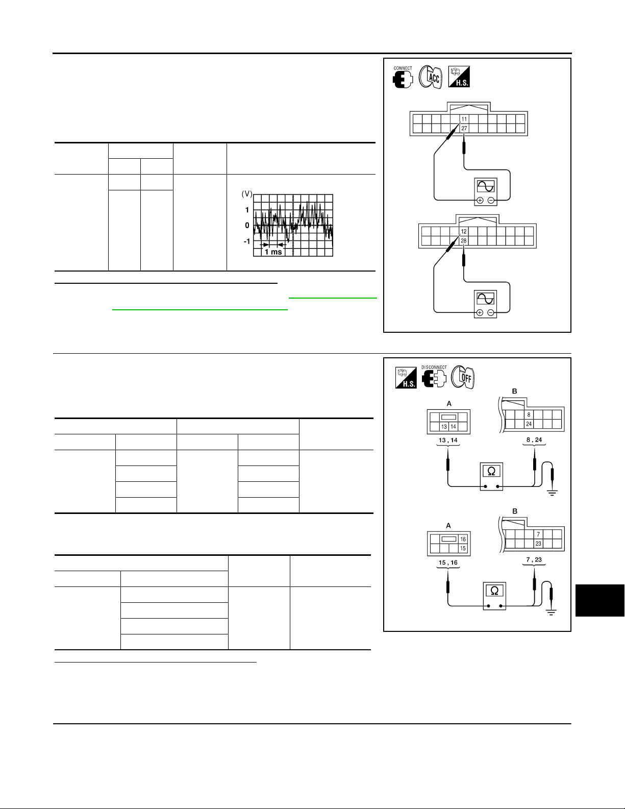
REAR DOOR TWEETER
< COMPONENT DIAGNOSIS >
1. Connect audio amp. connectors and suspect speaker connector.
2. Turn ignition switch to ACC.
3. Push “POWER” switch.
4. Check the signal between audio amp. harness connectors B159
terminals with CONSULT-III or oscilloscope.
[PREMIUM AUDIO]
A
B
Connector
B159
Te rm in al s
(+) (-)
11 27
12 28
Condition
Receive
audio signal
Reference
signal
RJ H@/066D
Are audio signal voltage readings as specified?
YES >> Replace suspect speaker. Refer to AV-107 , "Removal
and Installation - Rear Door Tweeter".
NO >> GO TO 3
3.PRE-AMP HARNESS CHECK
1. Disconnect audio unit connector M44 and audio amp. connector
B159.
2. Check continuity between audio unit harness connector M44 (A)
and audio amp. harness connector B159 (B).
AB
Connector Terminal Connector Terminal
M44
13
14 24
15 7
16 23
B159
8
3. Check continuity between audio unit harness connector M44 (A)
and ground.
Continuity
Yes
C
D
E
F
G
@KMH@/616FA
H
I
J
K
L
A
Connector Terminal
13
M44
14
15
16
—Continuity
Ground No
Are the continuity test results as specified?
YES >> GO TO 4
NO >> • Check connector housings for disconnected or loose terminals.
•Repair harness or connector.
4.PRE-AMP SIGNAL CHECK
AV-59
M
AV
@KMH@/618FA
O
P
Page 65
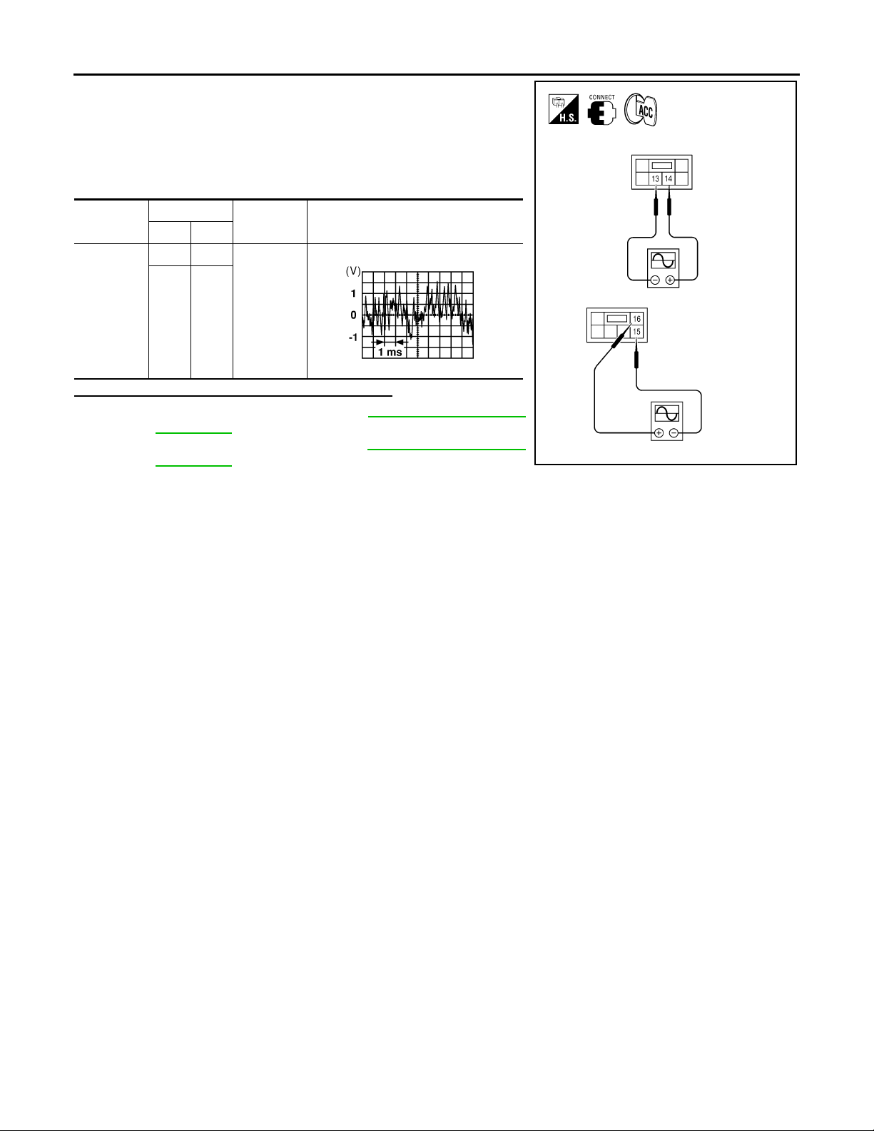
REAR DOOR TWEETER
< COMPONENT DIAGNOSIS >
1. Connect audio unit connector M44 and audio amp. connector
B159.
2. Turn ignition switch to ACC.
3. Push “POWER” switch.
4. Check the signal between audio unit harness connector M44
terminals with CONSULT-III or oscilloscope.
[PREMIUM AUDIO]
Connector
M44
Te rm in al s
(+) (-)
14 13
16 15
Condition
Receive
audio signal
Reference
signal
RJ H@/066D
Is the audio signal voltage reading as specified?
YES >> Replace audio amp. Refer to AV-104, "Removal and
Installation".
NO >> Replace audio unit. Refer to AV-103, "
Removal and
Installation".
@VMH@07/ 3YY
AV-60
Page 66
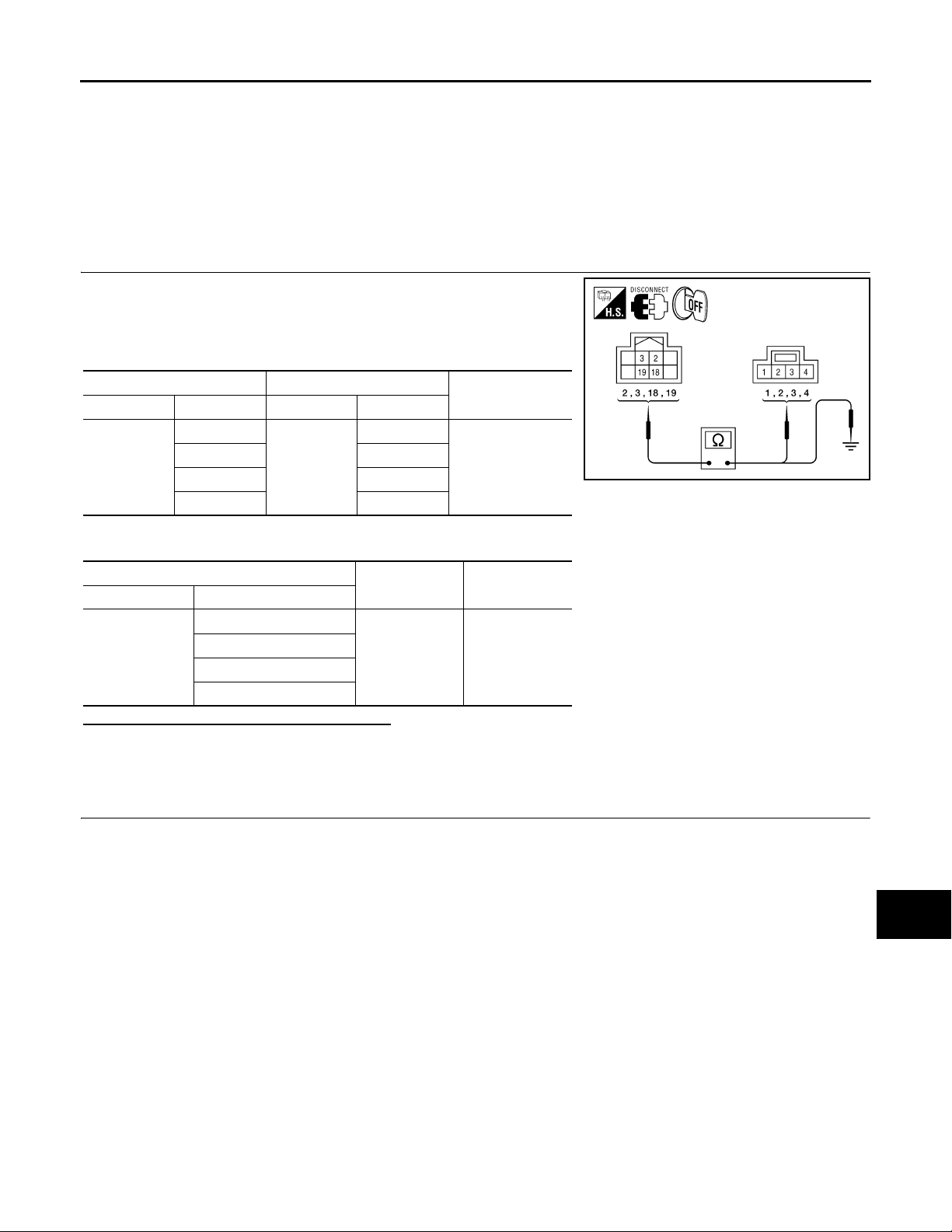
< COMPONENT DIAGNOSIS >
SUBWOOFER
[PREMIUM AUDIO]
SUBWOOFER
Description INFOID:0000000004095435
The audio unit sends audio signals to the audio amp. The audio amp. amplifies the audio signals before sending them to the subwoofer using the audio signal circuits.
Diagnosis Procedure INFOID:0000000004095436
1.SPEAKER HARNESS CHECK
1. Disconnect audio amp. connector B158 and subwoofer connector B72.
2. Check continuity between audio amp. harness connector B158
(A) and subwoofer harness connector B72 (B).
AB
Connector Terminal Connector Terminal
B158
2
33
18 2
19 4
B72
1
Continuity
Yes
@KMH@/620FA
3. Check continuity between audio amp. harness connector B158 (A) and ground.
A
Connector Terminal
2
B158
3
18
19
—Continuity
Ground No
Are the continuity test results as specified?
YES >> GO TO 2
NO >> • Check connector housings for disconnected or loose terminals.
•Repair harness or connector.
2.SPEAKER SIGNAL CHECK
A
B
C
D
E
F
G
H
I
J
K
L
AV-61
M
AV
O
P
Page 67
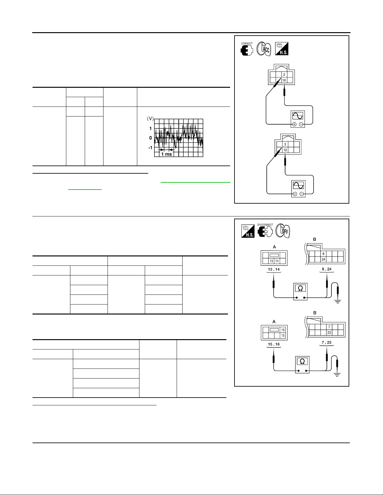
SUBWOOFER
< COMPONENT DIAGNOSIS >
1. Connect audio amp. connector B158 and subwoofer connector
B72.
2. Turn ignition switch to ACC.
3. Push “POWER” switch.
4. Check the signal between audio amp. harness connector B158
terminals with CONSULT-III or oscilloscope.
[PREMIUM AUDIO]
Connector
B158
Te rm in al s
(+) (-)
218
319
Condition
Receive au-
dio signal
Reference
signal
RJ H@/066D
Is the audio signal voltage as specified?
YES >> Replace subwoofer. Refer to AV-109, "Removal and
Installation".
NO >> GO TO 3
3.PRE-AMP HARNESS CHECK
1. Disconnect audio unit connector M44 and audio amp. connector
B159.
2. Check continuity between audio unit harness connector M44 (A)
and audio amp. harness connector B159 (B).
AB
Connector Terminal Connector Terminal
M44
13
14 24
15 7
16 23
B159
8
3. Check continuity between audio unit harness connector M44 (A)
and ground.
Continuity
Yes
@KMH@/621FA
A
Connector Terminal
13
M44
14
15
16
—Continuity
Ground No
Are the continuity test results as specified?
YES >> GO TO 4
NO >> • Check connector housings for disconnected or loose terminals.
•Repair harness or connector.
4.PRE-AMP SIGNAL CHECK
AV-62
@KMH@/618FA
Page 68
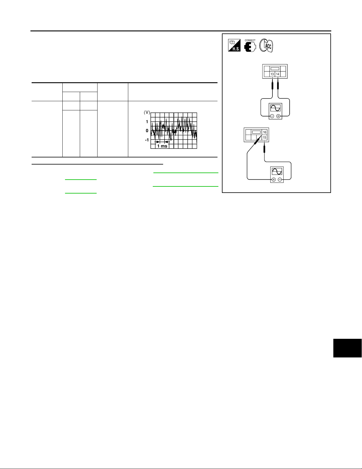
SUBWOOFER
< COMPONENT DIAGNOSIS >
1. Connect audio unit connector M44 and audio amp. connector
B159.
2. Turn ignition switch to ACC.
3. Push “POWER” switch.
4. Check the signal between audio unit harness connector M44
terminals with CONSULT-III or oscilloscope.
[PREMIUM AUDIO]
A
B
Connector
M44
Te rm i na ls
(+) (-)
14 13
16 15
Condition
Receive
audio signal
Reference
signal
RJ H@/066D
Is the audio signal voltage reading as specified?
YES >> Replace audio amp. Refer to AV-104, "Removal and
Installation".
NO >> Replace audio unit. Refer to AV-103, "
Removal and
Installation".
C
D
E
F
G
@VMH@07/ 3YY
H
I
J
AV
K
L
M
O
P
AV-63
Page 69
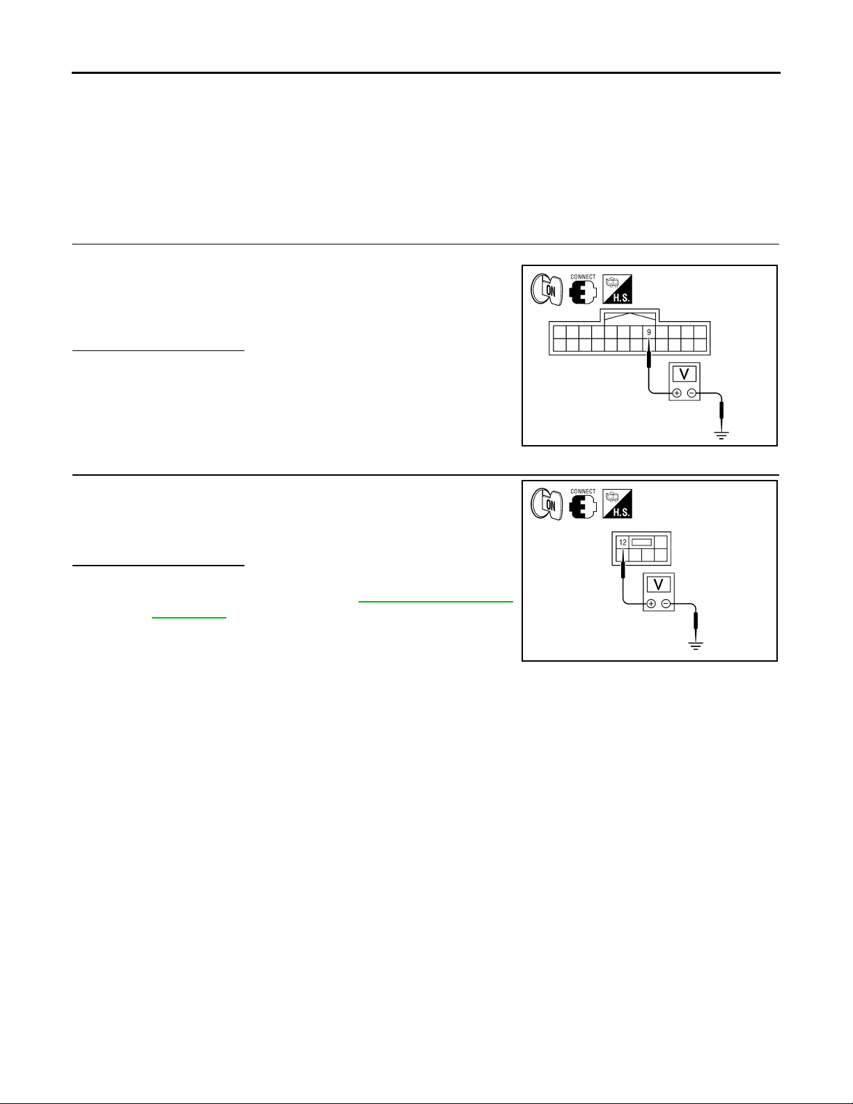
AMP ON SIGNAL CIRCUIT
< COMPONENT DIAGNOSIS >
[PREMIUM AUDIO]
AMP ON SIGNAL CIRCUIT
Description INFOID:0000000004095437
When the audio system is turned on, a voltage signal is supplied from the audio unit to the audio amp. When
this signal is received, the audio amp. will turn on.
Diagnosis Procedure INFOID:0000000004095438
1.CHECK AMP ON SIGNAL
1. Turn audio system ON.
2. Check voltage between audio amp. harness connector B159 terminal 9 and ground.
9 - Ground : More than 6.5V
Is battery voltage present?
YES >> Inspection End.
NO >> GO TO 2
@KMH@/622FA
2.CHECK AMP ON SIGNAL (AUDIO UNIT)
Check voltage between audio unit harness connector M44 terminal
12 and ground.
12 - Ground : More than 6.5V
Is battery voltage present?
YES >> Repair harness or connector.
NO >> Replace audio unit. Refer to AV-103, "
Installation".
Removal and
@KMH@/623FA
AV-64
Page 70
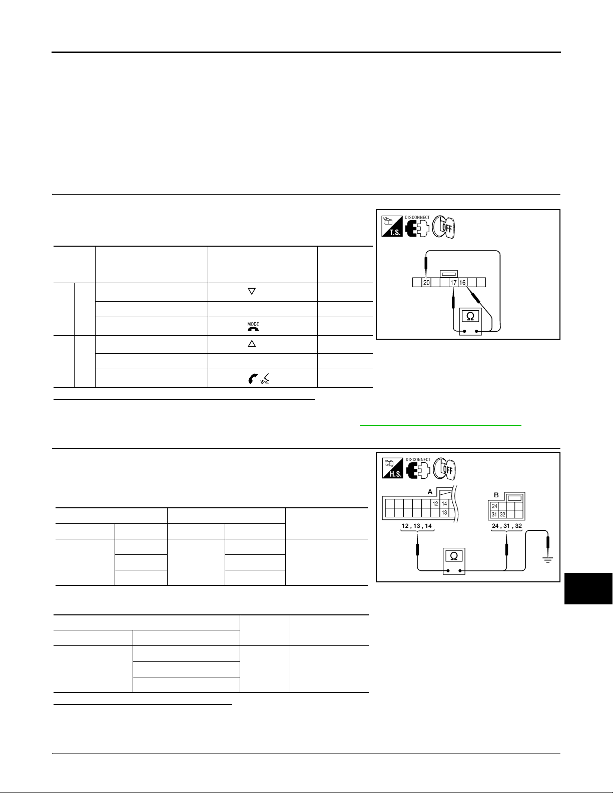
< COMPONENT DIAGNOSIS >
STEERING SWITCH
[PREMIUM AUDIO]
STEERING SWITCH
Description INFOID:0000000004459271
When one of the steering wheel audio control switches is pushed, the resistance in the steering wheel audio
control switch circuit changes depending on which button is pushed.
Diagnosis Procedure INFOID:0000000004459272
1.CHECK STEERING WHEEL AUDIO CONTROL SWITCH RESISTANCE
1. Turn ignition switch OFF.
2. Disconnect steering wheel audio control switch connector M102.
3. Check resistance between steering switch connector terminals.
Resistance
Te rm inal S i gn a l na m e C on dition
16 17
20 17
Seek (down)
Volume (down) Depress VOL do wn switch. 487
Mode/end
Seek (up)
Volume (up) Depress VOL up sw it ch . 487
Phone/send
Depress switch.
Depress switch.
Depress switch.
Depress switch.
(Ω)
(Approx.)
165
0
VJH@3346 D
165
0
Do the steering wheel audio control switches check OK?
YES >> GO TO 2
NO >> Replace steering wheel audio control switch. Refer to AV-1 08, "Removal and Installation".
2.CHECK HARNESS
A
B
C
D
E
F
G
H
I
J
1. Disconnect Bluetooth control unit harness connector B141 and
spiral cable harness connector M30.
2. Check continuity between Bluetooth control unit harness connector B141 (A) and spiral cable harness connector M30 (B).
AB
Connector Terminal Connector Terminal
B141
12
M30
14 31
24
Continuity
Yes13 32
3. Check continuity between Bluetooth control unit connector B141 (A) and ground.
A
Connector Terminal
12
B141
14
—Continuity
Ground No13
Are the continuity results as specified?
YES >> GO TO 3
NO >> Repair harness.
3.SPIRAL CABLE CHECK
K
L
M
@KMH@/624FA
AV
O
P
AV-65
Page 71
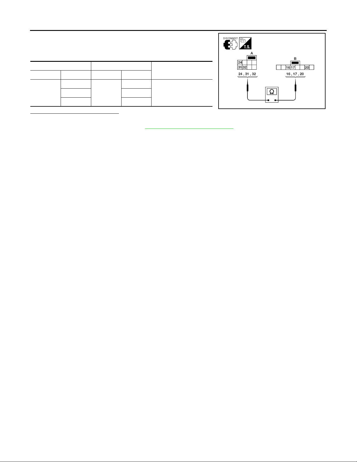
STEERING SWITCH
< COMPONENT DIAGNOSIS >
1. Disconnect spiral cable connector M102.
2. Check continuity between spiral cable harness connector M30
(A) and M102 (B).
[PREMIUM AUDIO]
AB
Connector Terminal Connector Terminal
M30
24
M102
32 16
20
Does the spiral cable check OK?
YES >> Inspection End.
NO >> Replace spiral cable. Refer to SR-6, "
Continuity
Yes31 17
@VKH@05/ 1YY
Removal and Installation".
AV-66
Page 72
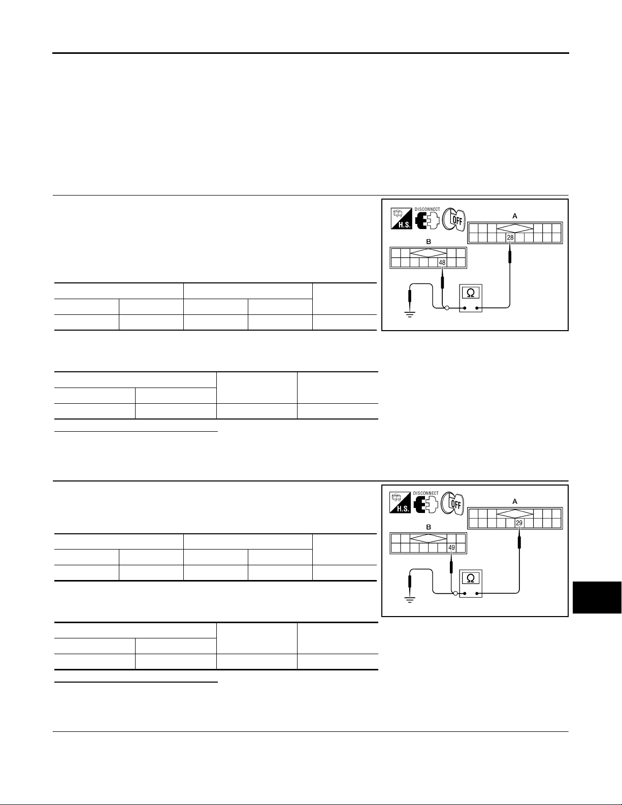
COMMUNICATION SIGNAL CIRCUIT
< COMPONENT DIAGNOSIS >
[PREMIUM AUDIO]
COMMUNICATION SIGNAL CIRCUIT
SATELLITE RADIO TUNER
SATELLITE RADIO TUNER : Description INFOID:0000000004095441
Communication signals are exchanged between the audio unit and satellite radio tuner using the communication circuits.
SATELLITE RADIO TUNER : Diagnosis Procedure INFOID:0000000004095442
1.CHECK HARNESS - REQ1
1. Turn ignition switch OFF.
2. Disconnect satellite radio tuner (factory installed) connector M41
and audio unit connector M42.
3. Check continuity between satellite radio tuner (factory installed)
harness connector M41 (A) terminal 28 and audio unit harness
connector M42 (B) terminal 48.
AB
Connector Terminal Connector Terminal
M41 28 M42 48 Yes
4. Check continuity between satellite radio tuner (factory installed)
harness connector M41 (A) terminal 28 and ground.
Continuity
@KMH@/6/8FA
A
B
C
D
E
F
G
H
A
Connector Terminal
M41 28 Ground No
—Continuity
Are continuity results as specified?
YES >> GO TO 2
NO >> Repair harness or connector.
2.CHECK HARNESS - TXD
1. Check continuity between satellite radio tuner (factory installed)
harness connector M41 (A) terminal 29 and audio unit harness
connector M42 (B) terminal 49.
AB
Connector Terminal Connector Terminal
M41 29 M42 49 Yes
Continuity
2. Check continuity between satellite radio tuner (factory installed)
harness connector M41 (A) terminal 29 and ground.
A
Connector Terminal
M41 29 Ground No
—Continuity
Are continuity results as specified?
YES >> GO TO 3
NO >> Repair harness or connector.
3.CHECK HARNESS - RXD
I
J
K
L
M
AV
@KMH@/6/6FA
O
P
AV-67
Page 73
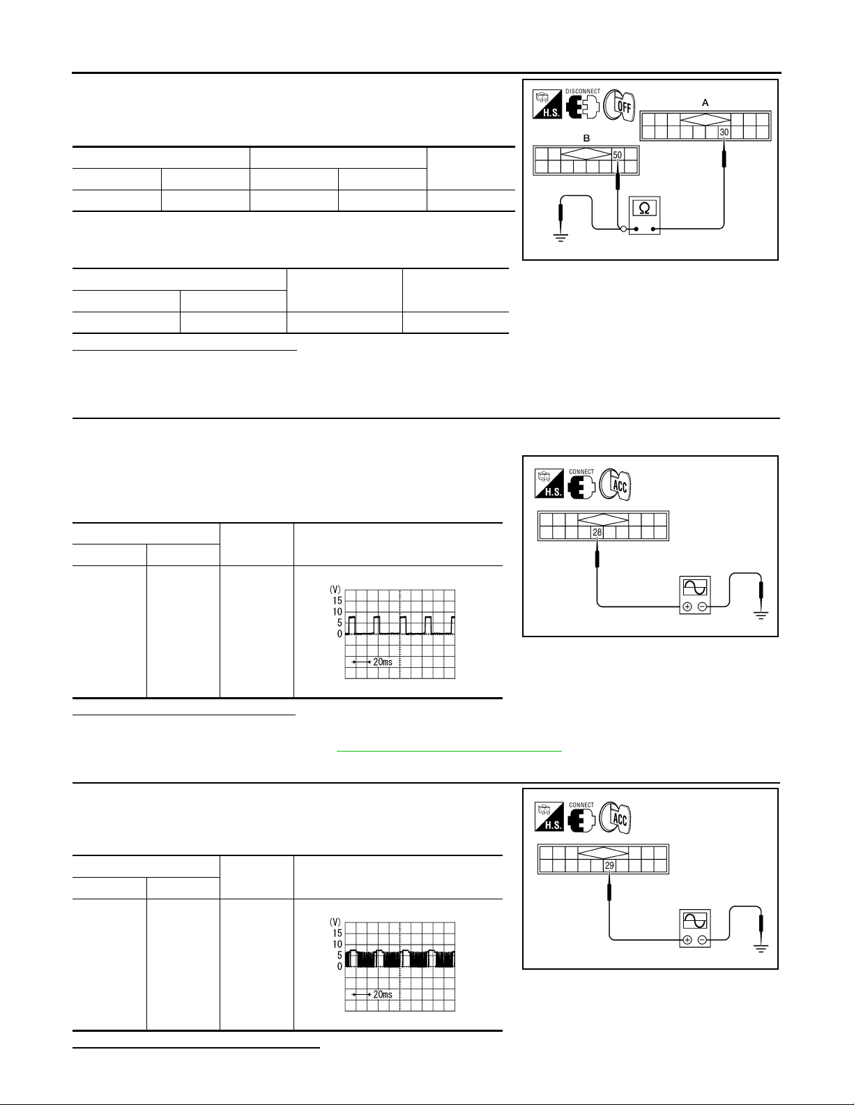
COMMUNICATION SIGNAL CIRCUIT
< COMPONENT DIAGNOSIS >
1. Check continuity between satellite radio tuner (factory installed)
harness connector M41 (A) terminal 30 and audio unit harness
connector M42 (B) terminal 50.
[PREMIUM AUDIO]
AB
Connector Terminal Connector Terminal
M41 30 M42 50 Yes
Continuity
2. Check continuity between satellite radio tuner (factory installed)
harness connector M41 (A) terminal 30 and ground.
A
Connector Terminal
M41 30 Ground No
—Continuity
Are continuity results as specified?
YES >> GO TO 4
NO >> Repair harness or connector.
4.CHECK REQ1 SIGNAL
1. Connect satellite radio tuner (factory installed) connector and audio unit connector.
2. Turn ignition switch to ACC
3. Check signal between satellite radio tuner (factory installed) harness connector M41 terminal 28 and ground with CONSULT-III
or oscilloscope.
(+)
Connector Terminal
(-) Reference signal
@KMH@/6/7FA
M41 28 Ground
RJ HA2714D
Are voltage readings as specified?
YES >> GO TO 5
NO >> Replace audio unit. Refer to AV-103, "
Removal and Installation".
5.CHECK TXD SIGNAL
Check signal between satellite radio tuner (factory installed) harness
connector M41 terminal 29 and ground with CONSULT-III or oscilloscope.
(+)
Connector Terminal
M41 29 Ground
Are the voltage readings as specified?
(-) Reference signal
RJ HA2713D
VJH@3433 D
VJH@3434 D
AV-68
Page 74
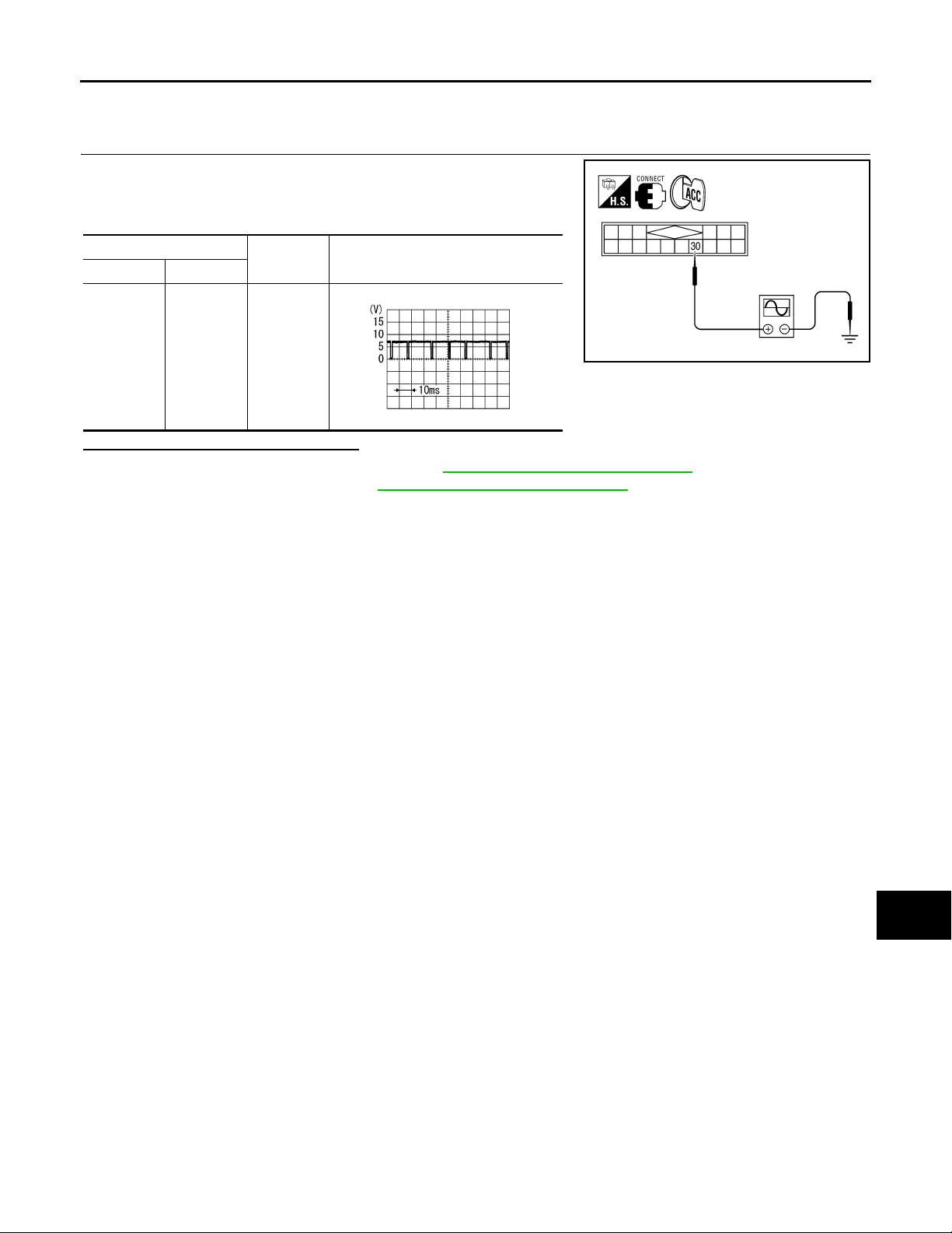
COMMUNICATION SIGNAL CIRCUIT
< COMPONENT DIAGNOSIS >
YES >> GO TO 6
NO >> Replace satellite radio tuner.
6.CHECK RXD SIGNAL
[PREMIUM AUDIO]
A
Check signal between satellite radio tuner (factory installed) harness
connector M41 terminal 30 and ground with CONSULT-III or oscilloscope.
(+)
Connector Terminal
M41 30 Ground
(-) Reference signal
RJ HA2715D
Are the voltage readings as specified?
YES >> Replace satellite radio tuner. Refer to AV-117 , "Removal and Installation".
NO >> Replace audio unit. Refer to AV-10 3, "
Removal and Installation".
VJH@3435 D
B
C
D
E
F
G
H
I
AV
J
K
L
M
O
P
AV-69
Page 75
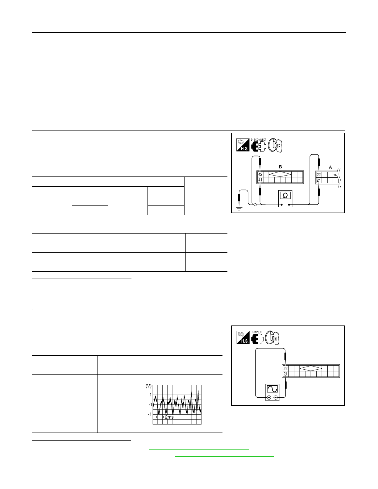
SOUND SIGNAL CIRCUIT
< COMPONENT DIAGNOSIS >
[PREMIUM AUDIO]
SOUND SIGNAL CIRCUIT
SATELLITE RADIO TUNER
SATELLITE RADIO TUNER : Description INFOID:0 000000004459273
Left and right channel audio signals are supplied from the satellite radio tuner to the audio unit through the
sound signal circuits.
SATELLITE RADIO TUNER : Diagnosis Procedure INFOID:0000000004459274
LEFT CHANNEL
1.CHECK HARNESS
1. Turn ignition switch OFF.
2. Disconnect satellite radio tuner (factory installed) connector M41
and audio unit connector M42.
3. Check continuity between satellite radio tuner (factory installed)
connector M41 (A) and audio unit connector M42 (B).
AB
Connector Terminal Connector Terminal
M41
21
22 42
M42
41
Continuity
Yes
4. Check continuity between satellite radio tuner (factory installed) connector M41 (A) and ground.
A
Connector Terminal
M41
21
22
—Continuity
Ground No
Are continuity results as specified?
YES >> GO TO 2
NO >> Repair harness or connector.
2.CHECK LEFT CHANNEL AUDIO SIGNAL
1. Connect satellite radio tuner (factory installed) and audio unit.
2. Turn ignition switch ON.
3. Check signal between satellite radio tuner (factory installed)
connector M41 terminals 21 and 22 with CONSULT-III or oscilloscope.
(+) (-)
Connector Terminal Terminal
Reference signal
@KMH@/60/FA
M41 22 21
RJ HA25/ 8D
Are voltage readings as specified?
YES >> Replace audio unit. Refer to AV-103, " Removal and Installation".
NO >> Replace satellite radio tuner. Refer to AV-117, "
Removal and Installation".
RIGHT CHANNEL
AV-70
@KMH@/77/FA
Page 76
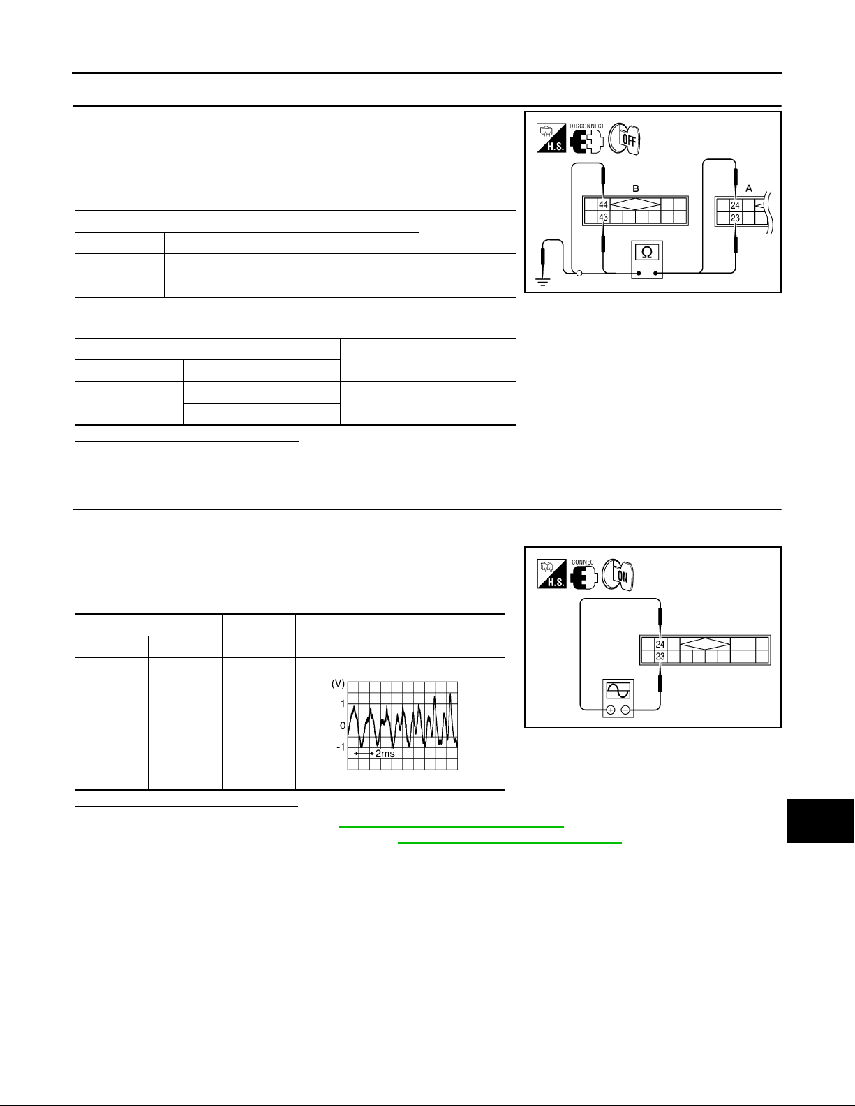
< COMPONENT DIAGNOSIS >
SOUND SIGNAL CIRCUIT
[PREMIUM AUDIO]
1.CHECK HARNESS
1. Turn ignition switch OFF.
2. Disconnect satellite radio tuner (factory installed) connector M41
and audio unit connector M42.
3. Check continuity between satellite radio tuner (factory installed)
M41 (A) and audio unit M42 (B).
AB
Connector Terminal Connector Terminal
M41
23
24 44
M42
43
Continuity
Yes
4. Check continuity between satellite radio tuner (factory installed) connector M41 (A) and ground.
A
Connector Terminal
M41
23
24
—Continuity
Ground No
Are continuity results as specified?
YES >> GO TO 2
NO >> Repair harness or connector.
2.CHECK RIGHT CHANNEL AUDIO SIGNAL
A
B
C
D
@KMH@/600FA
E
F
G
H
1. Connect satellite radio tuner (factory installed) and audio unit.
2. Turn ignition switch ON.
3. Check signal between satellite radio tuner (factory installed)
connector M41 terminals 23 and 24 with CONSULT-III or oscilloscope.
(+) (-)
Connector Terminal Terminal
M41 24 23
Reference signal
RJ HA25/ 8D
Are voltage readings as specified?
YES >> Replace audio unit. Refer to AV-10 3, "Removal and Installation".
NO >> Replace satellite radio tuner. Refer to AV-117 , "
Removal and Installation".
@KMH@/770FA
I
J
K
L
M
AV
O
AV-71
P
Page 77
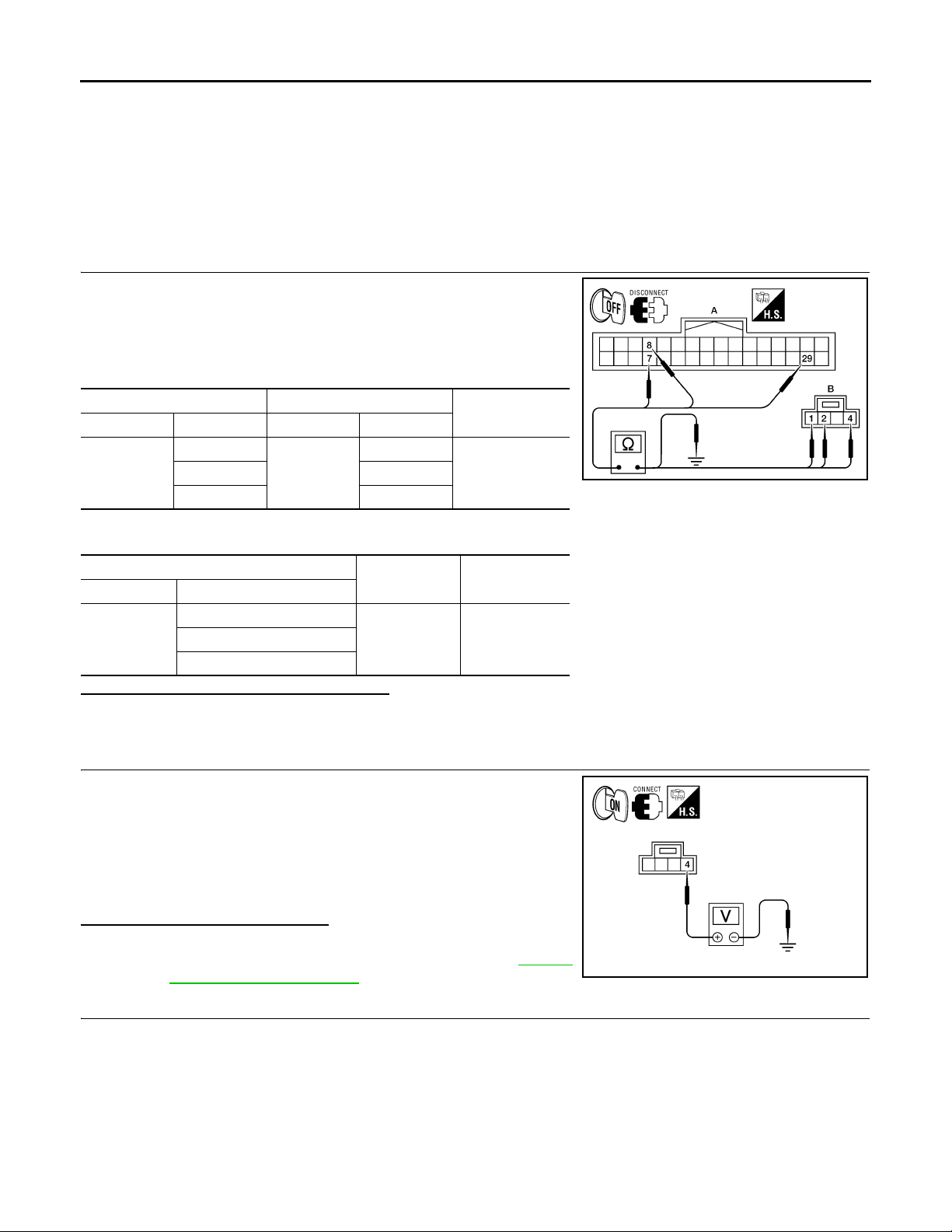
MICROPHONE SIGNAL CIRCUIT
< COMPONENT DIAGNOSIS >
[PREMIUM AUDIO]
MICROPHONE SIGNAL CIRCUIT
Description INFOID:0000000004095445
Voice signals are transmitted from the microphone to the Bluetooth control unit using the microphone signal
circuits.
Diagnosis Procedure INFOID:0000000004095446
1.CHECK HARNESS BETWEEN BLUETOOTH CONTROL UNIT AND MICROPHONE
1. Turn ignition switch OFF.
2. Disconnect Bluetooth control unit connector and microphone
connector.
3. Check continuity between Bluetooth control unit harness connector B141 (A) and microphone harness connector R8 (B).
AB
Connector Terminal Connector Terminal
B141
7
R8
29 4
1
Continuity
Yes82
4. Check continuity between Bluetooth control unit harness connector B141 (A) and ground.
A
Connector Terminal
7
B141
29
—Continuity
Ground No8
Are the continuity test results as specified?
YES >> GO TO 2
NO >> Repair harness or connector.
2.CHECK MICROPHONE POWER SUPPLY
1. Connect Bluetooth control unit connector and microphone connector.
2. Turn ignition switch ON.
3. Check voltage between microphone harness connector R8 terminal 4 and ground.
VJH@4684 D
4 - Ground : Approx. 5V
Is voltage reading approx. 5 volts?
YES >> GO TO 3
NO >> Replace Bluetooth control unit. Refer to AV-111 ,
"Removal and Installation".
3.CHECK MICROPHONE SIGNAL
AV-72
VJH@4685 D
Page 78
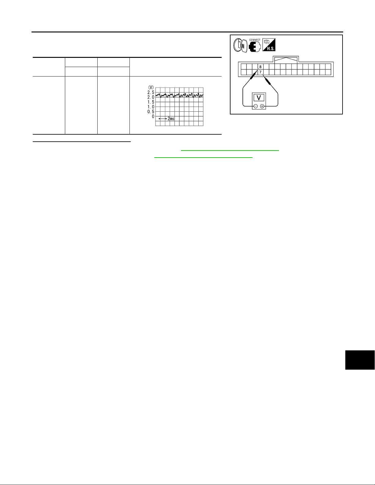
MICROPHONE SIGNAL CIRCUIT
< COMPONENT DIAGNOSIS >
Check signal between Bluetooth control unit harness connector
B141 terminals 7 and 8 with CONSULT-III or and oscilliscope.
[PREMIUM AUDIO]
A
Connector
B141 7 8
(+) (-)
Te rm i n al Te rm i na l
Reference signal
While speaking into MIC
OJ H A4/ 26I
Are voltage readings as specified?
YES >> Replace Bluetooth control unit. Refer to AV-111, "Removal and Installation".
NO >> Replace microphone. Refer to AV-113 , "
Removal and Installation".
B
C
@KMH@/823FA
D
E
F
G
H
AV
I
J
K
L
M
O
P
AV-73
Page 79
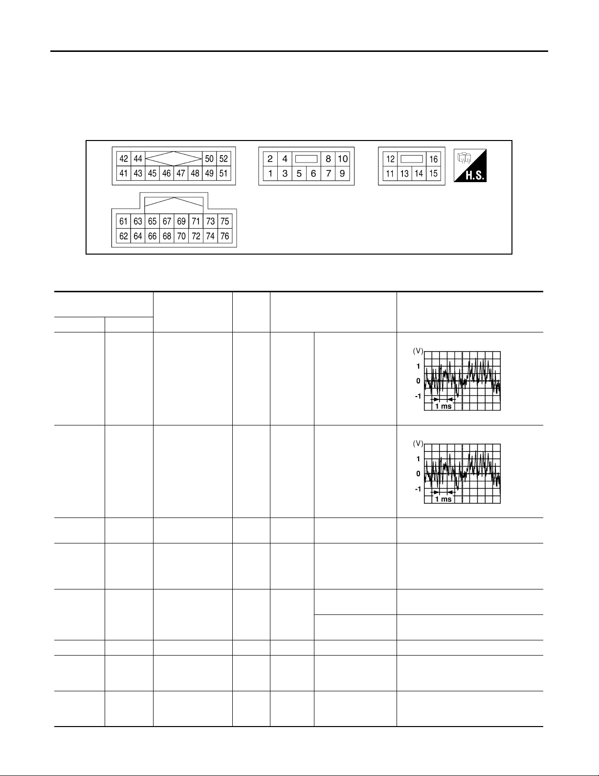
AUDIO UNIT
< ECU DIAGNOSIS >
[PREMIUM AUDIO]
ECU DIAGNOSIS
AUDIO UNIT
Reference Value INFOID:0000000004095447
TERMINAL LAYOUT
@VMH@/684YY
PHYSICAL VALUES
Te rm i na l
(Wire color)
+–
2
(W)
4
(Y)
6
(Y)
7
(GR)
8
(R)
9–Shield –– – 0V
10
(G/B)
12
(G/W)
1
(B)
3
(BR)
Ground Battery power Input – – Battery voltage
Ground
Ground Illumination signal Input OFF
Ground ACC signal Input
Ground Amp ON signal Output
Item
Audio sound signal
front LH
Audio sound signal
front RH
Illumination control
signal
Signal
input/
output
Output
Output
Input
Ignition
switch
ON
Ignition
switch
ON
Ignition
switch
ON
Ignition
switch
ON
Ignition
switch
ON
Condition
Receive audio signal
Receive audio signal
Illumination control
switch is operated
by lighting switch in
1st position.
Lighting switch is in
1st position.
Lighting switch is
OFF.
–Battery voltage
–Battery voltage
Reference value
(Approx.)
Changes between 0 and 12V
Battery voltage
0V
RJ H@/066D
RJ H@/066D
AV-74
Page 80
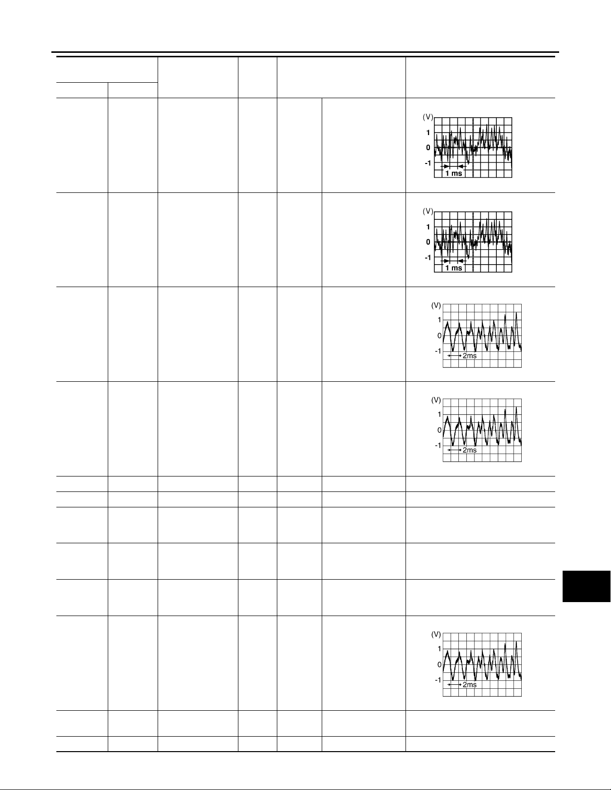
< ECU DIAGNOSIS >
AUDIO UNIT
[PREMIUM AUDIO]
Te rm in al
(Wire color)
+–
14
(BR)
16
(L)
42
(R)
13
(B/R)
15
(B/W)
41
(G)
Item
Audio sound signal
rear LH
Audio sound signal
rear RH
Satellite radio audio signal LH
Signal
input/
output
Output
Output
Input
Ignition
switch
ON
Ignition
switch
ON
Ignition
switch
ON
Condition
Receive audio signal
Receive audio signal
Satellite radio tuner
operating
Reference value
(Approx.)
RJ H@/066D
RJ H@/066D
A
B
C
D
E
F
G
H
44
(B)
45 – Ground – – – 0V
46 – Data ground – – – 0V
48
(O)
49
(P)
50
(L)
62
(W)
43
(W)
–
–
–
61
(B)
Satellite radio audio signal RH
REQ (SAT→AV
control unit)
RX (SAT→AV c ontrol unit)
TX (AV control
unit→SAT)
Te le pho ne s i gn a l
input
Input
Input
Input
Input
Input
Ignition
switch
ON
Ignition
switch
ON
Ignition
switch
ON
Ignition
switch
ON
Ignition
switch
ACC/ON
Satellite radio tuner
operating
–—
–—
–—
Bluetooth control
unit sends audio
signal
RJ HA25/ 8D
RJ HA25/ 8D
I
J
K
L
M
AV
O
P
63
(R)
64 – Shield – – – 0V
–Mute control – – – –
AV-75
RJ HA25/ 8D
Page 81
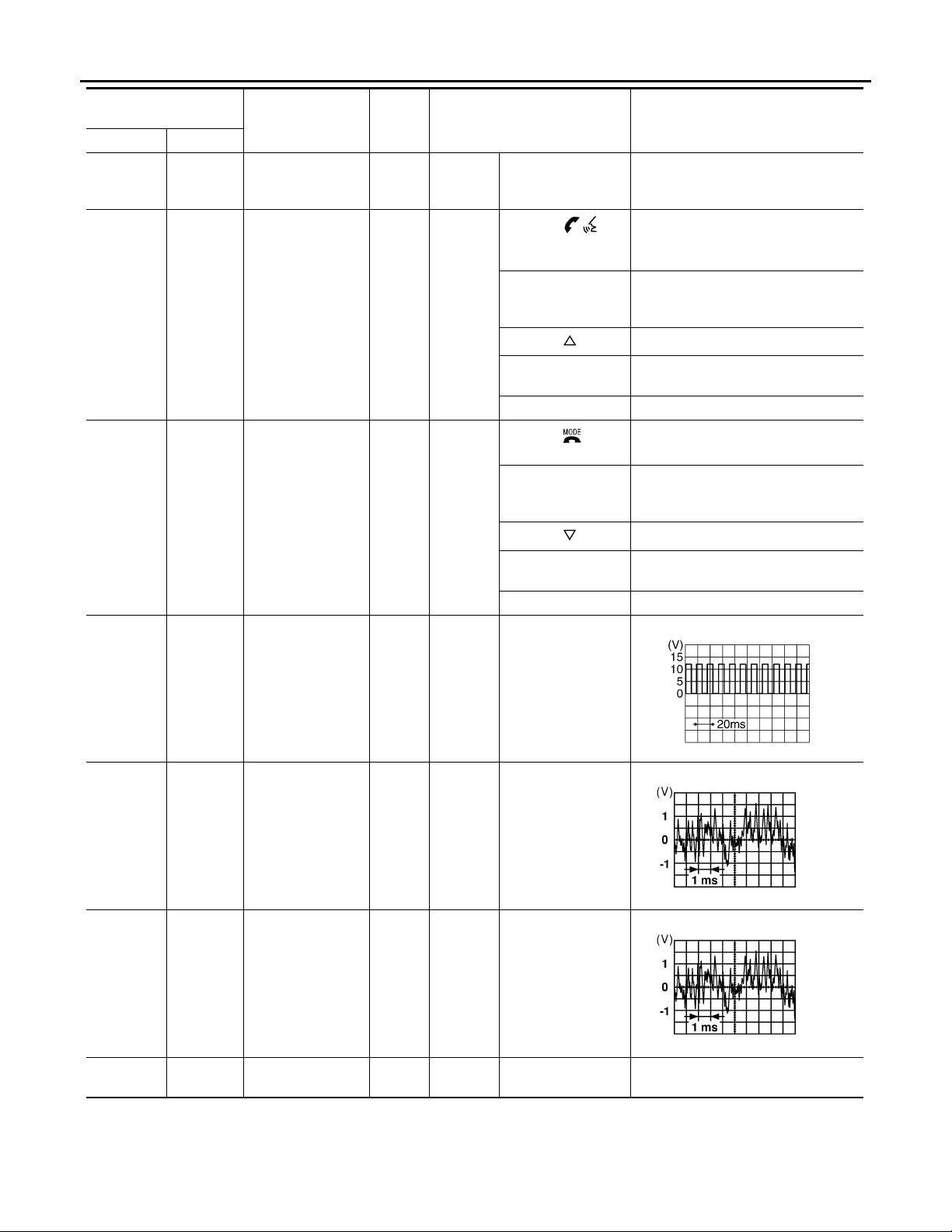
< ECU DIAGNOSIS >
AUDIO UNIT
[PREMIUM AUDIO]
Te rm i na l
(Wire color)
+–
67 – Shield –
69
(V)
70
(LG)
71
(O)
71
(O)
Item
Steering switch signal A
Steering switch signal B
Signal
input/
output
Input
Input
Ignition
switch
ON
Ignition
switch
ON
Ignition
switch
ON
Condition
–0V
Pressing
switch (with Bluetooth)
Pressing MODE
switch (without
Bluetooth)
Pressing switch
Pressing VOL up
switch
Except for above 5V
Pressing switch
(with Bluetooth)
Pressing PWR
switch (without
Bluetooth)
Pressing switch
Pressing VOL down
switch
Except for above 5 V
Reference value
(Approx.)
0.75
0.75V
0V
0V
2V
0V
0V
2V
73
(SB)
74
(W)
75
(B)
76
(B)
Ground
Ground
Ground
–Shield – – – 0V
Vehic le speed si gnal (8-pulse)
Auxiliary audio input RH (+)
Auxiliary audio input LH (+)
Input
Input
Input
Ignition
switch
ON
Ignition
switch
ON
Ignition
switch
ON
When vehicle speed
is approx. 40 km/h
(25 MPH)
Receive audio signal (AUX input)
Receive audio signal (AUX input)
OJ H @0824D
RJ H@/066D
RJ H@/066D
AV-76
Page 82
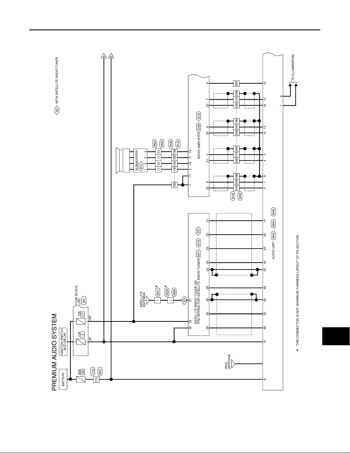
AUDIO UNIT
A
< ECU DIAGNOSIS >
[PREMIUM AUDIO]
Wiring Diagram INFOID:0000000004095448
A
B
C
D
E
F
G
AV
H
I
J
K
L
M
O
AV-77
P
@AMV @/066F
Page 83
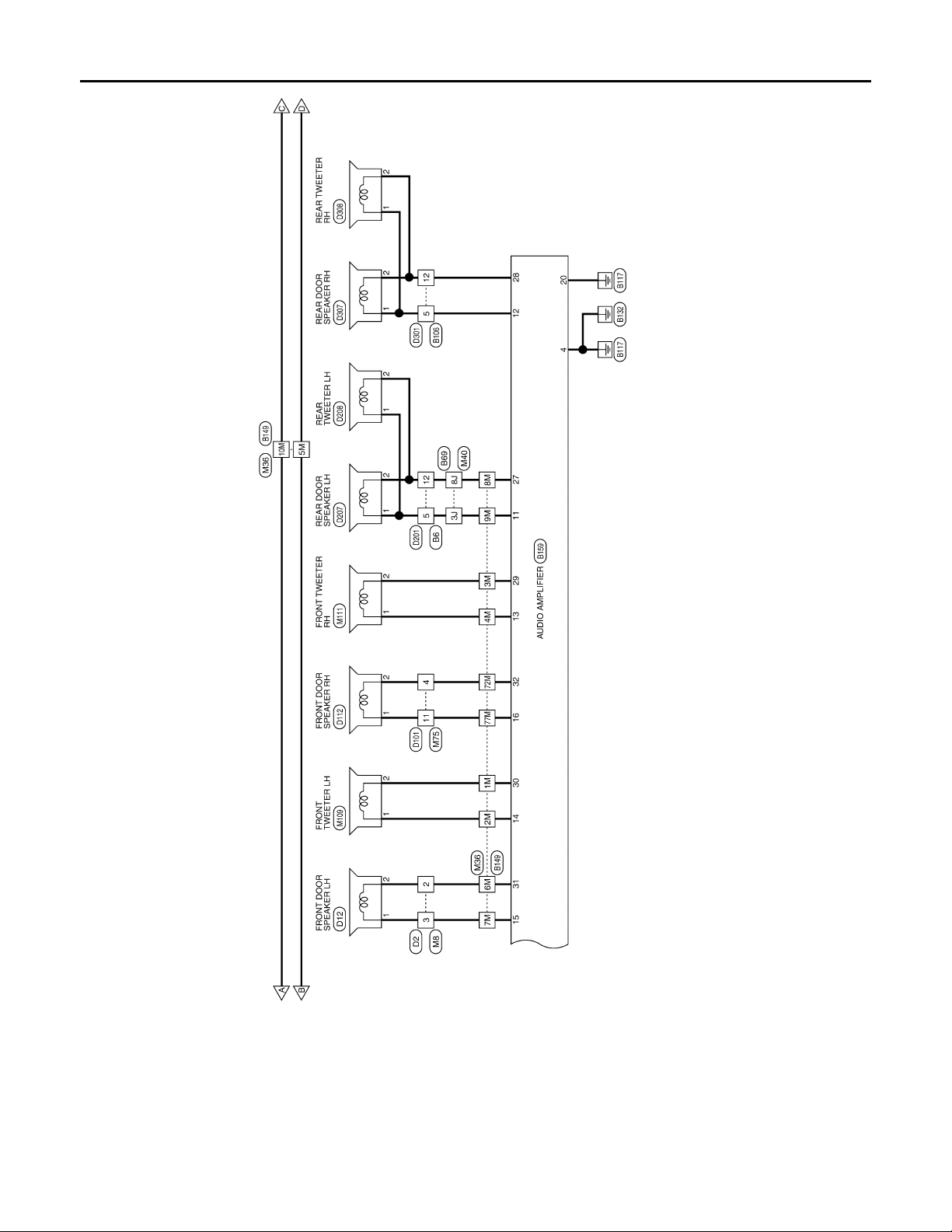
< ECU DIAGNOSIS >
A
AUDIO UNIT
[PREMIUM AUDIO]
AV-78
@AMV @/067F
Page 84
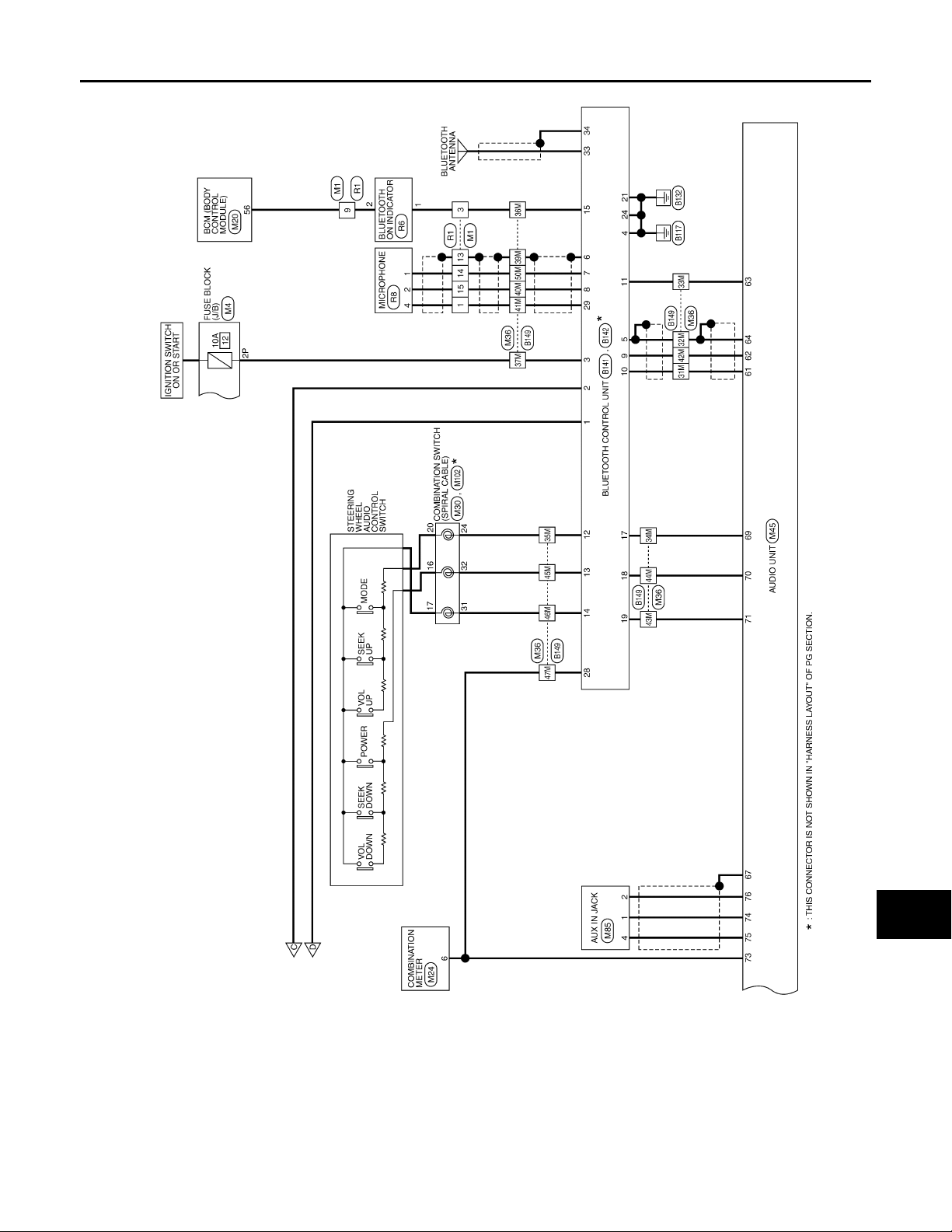
< ECU DIAGNOSIS >
A
AUDIO UNIT
[PREMIUM AUDIO]
A
B
C
D
E
F
G
AV
H
I
J
K
L
M
O
AV-79
@AMV @/068F
P
Page 85
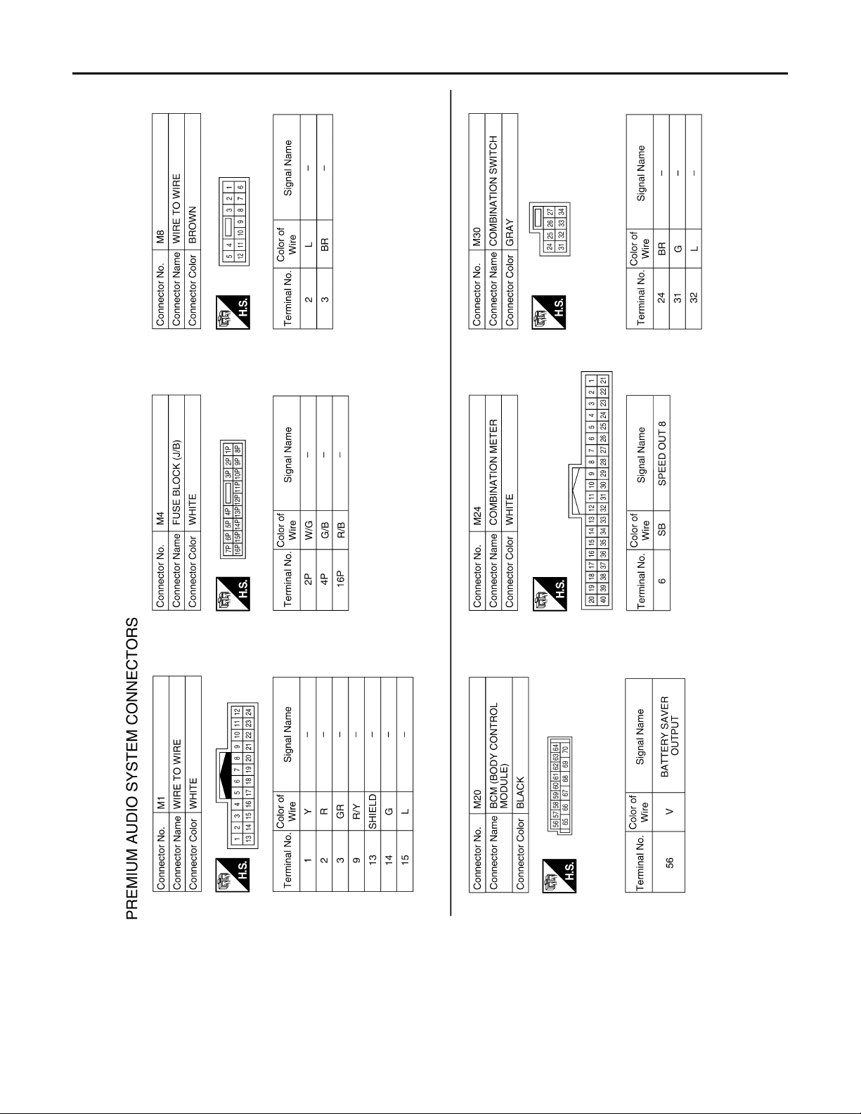
< ECU DIAGNOSIS >
AUDIO UNIT
[PREMIUM AUDIO]
AV-80
@AMH@/448FA
Page 86
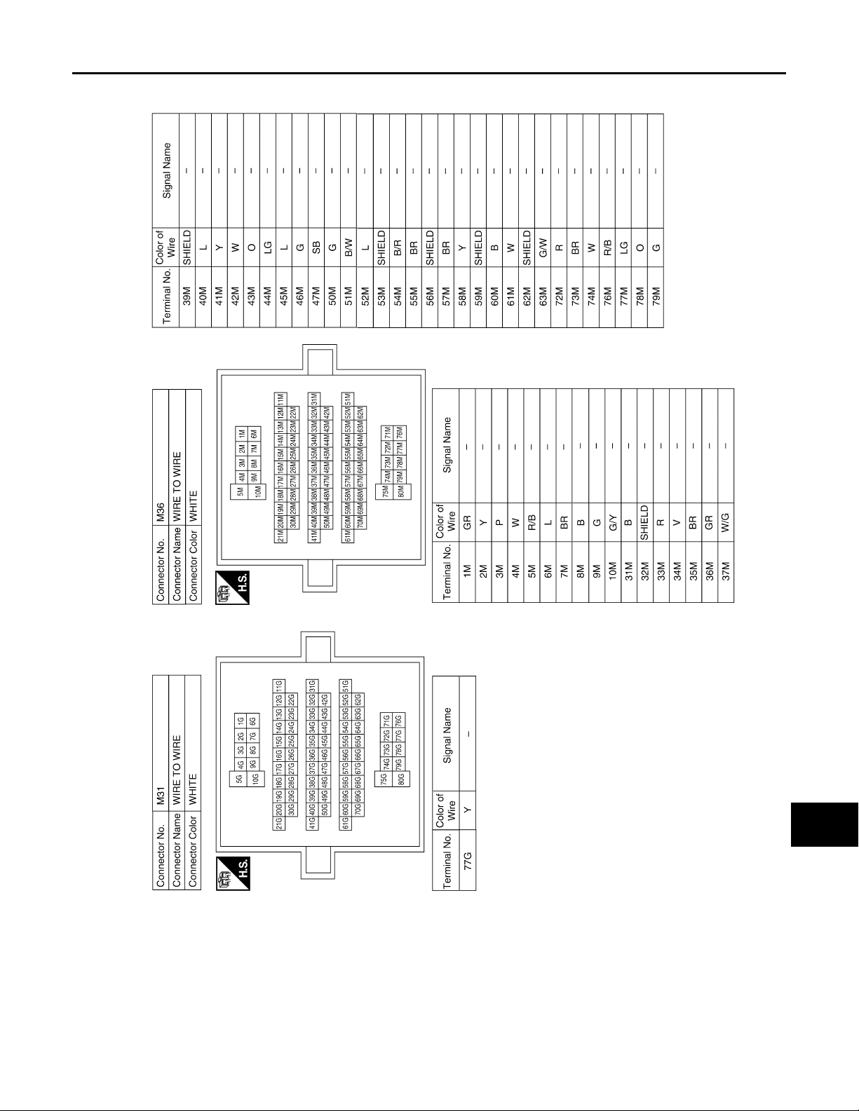
< ECU DIAGNOSIS >
AUDIO UNIT
[PREMIUM AUDIO]
A
B
C
D
E
F
G
AV
H
I
J
K
L
M
O
AV-81
@AMH@/45/FA
P
Page 87
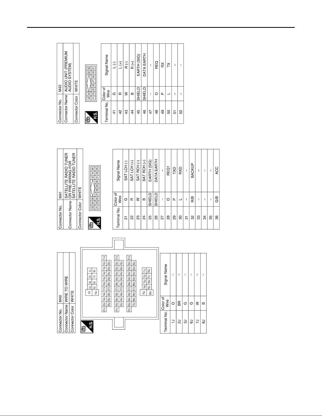
< ECU DIAGNOSIS >
AUDIO UNIT
[PREMIUM AUDIO]
AV-82
@AMH@/450FA
Page 88
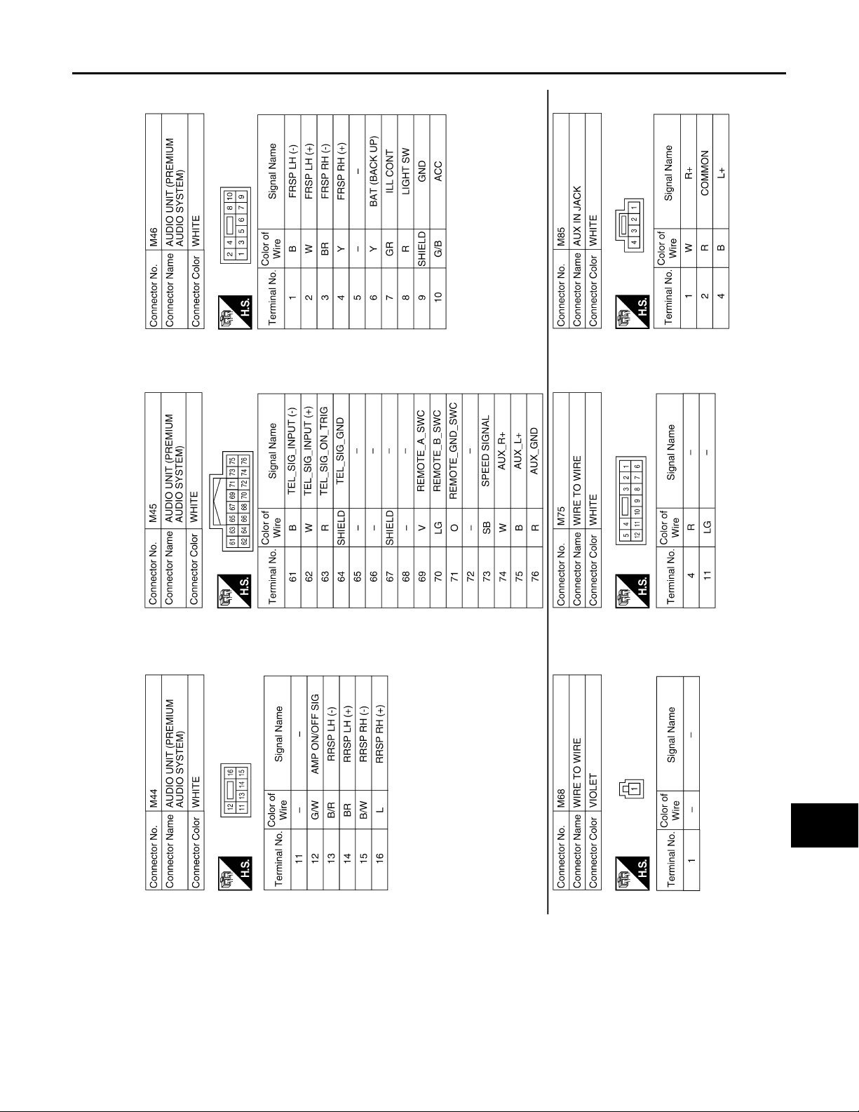
< ECU DIAGNOSIS >
AUDIO UNIT
[PREMIUM AUDIO]
A
B
C
D
E
F
G
AV
H
I
J
K
L
M
O
AV-83
@AMH@/451FA
P
Page 89
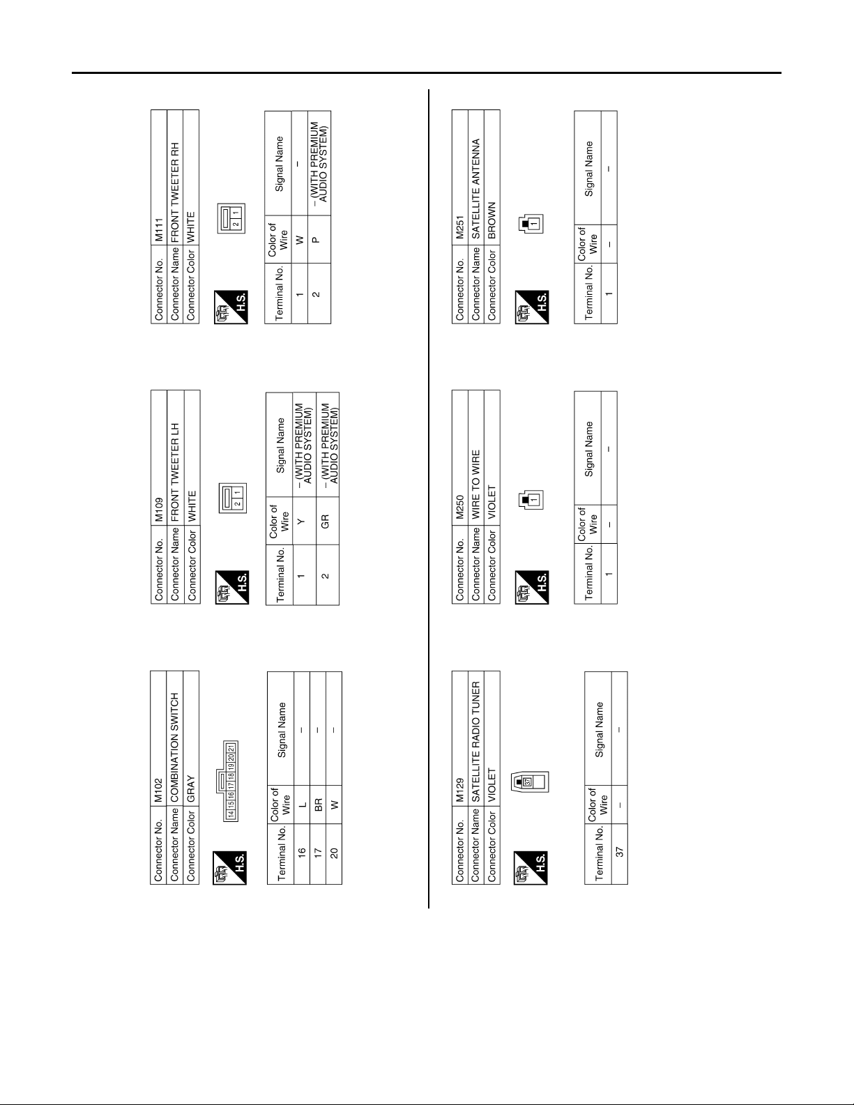
< ECU DIAGNOSIS >
AUDIO UNIT
[PREMIUM AUDIO]
AV-84
@AMH@/452FA
Page 90
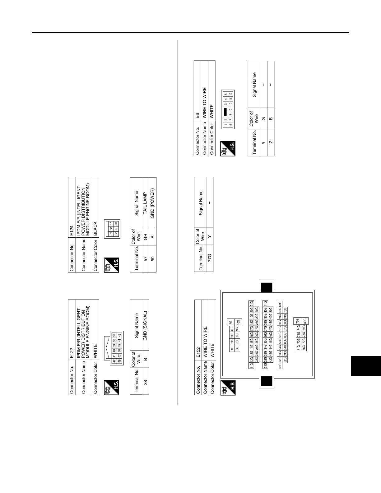
< ECU DIAGNOSIS >
AUDIO UNIT
[PREMIUM AUDIO]
A
B
C
D
E
F
G
AV
H
I
J
K
L
M
O
AV-85
@AMH@/453FA
P
Page 91
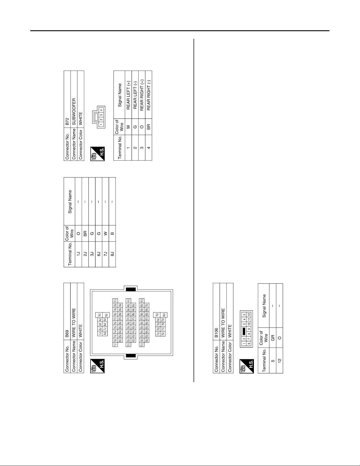
< ECU DIAGNOSIS >
AUDIO UNIT
[PREMIUM AUDIO]
AV-86
@AMH@/455FA
Page 92
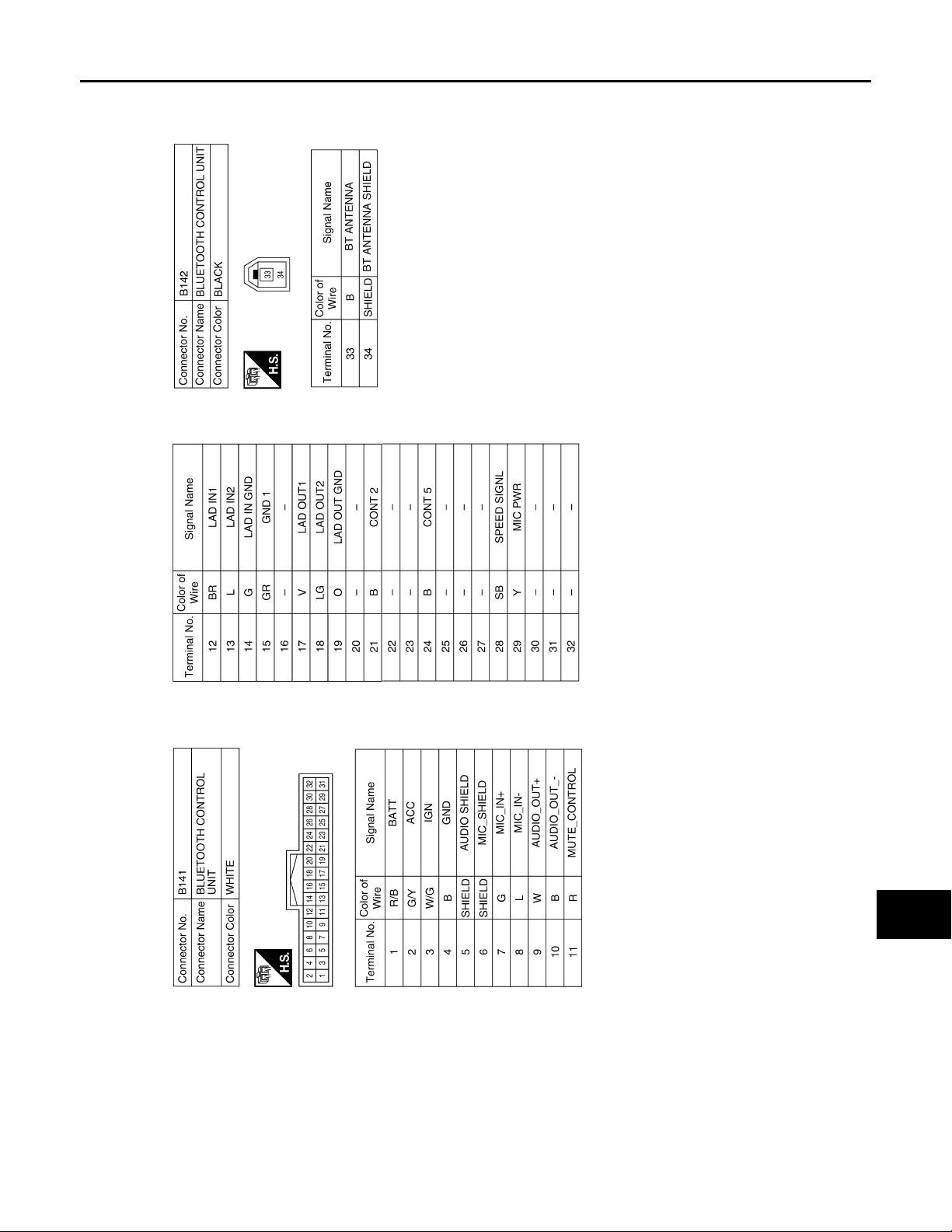
< ECU DIAGNOSIS >
AUDIO UNIT
[PREMIUM AUDIO]
A
B
C
D
E
F
G
AV
H
I
J
K
L
M
O
AV-87
@AMH@/454FA
P
Page 93
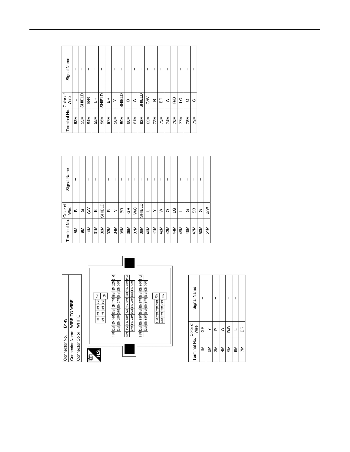
< ECU DIAGNOSIS >
AUDIO UNIT
[PREMIUM AUDIO]
AV-88
@AMH@/456FA
Page 94
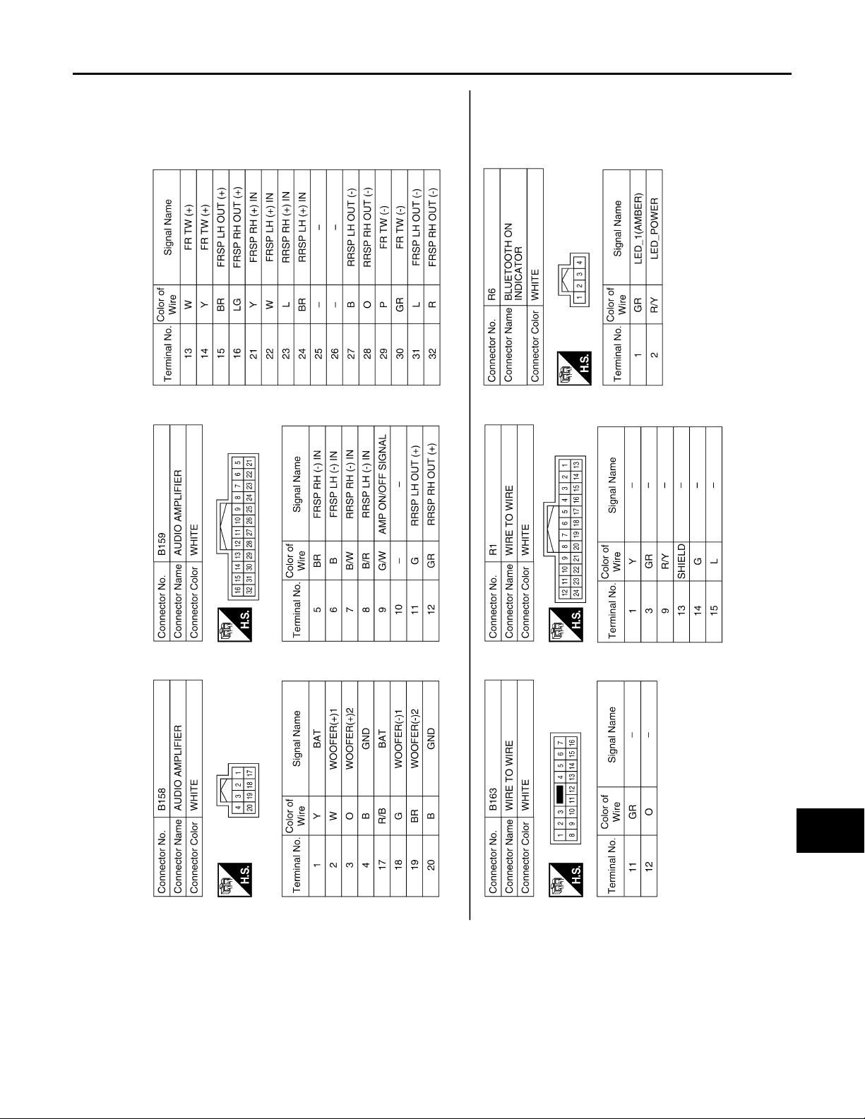
< ECU DIAGNOSIS >
AUDIO UNIT
[PREMIUM AUDIO]
A
B
C
D
E
F
G
AV
H
I
J
K
L
M
O
AV-89
@AMH@/457FA
P
Page 95
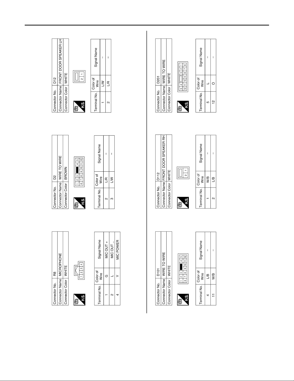
< ECU DIAGNOSIS >
AUDIO UNIT
[PREMIUM AUDIO]
AV-90
@AMH@/458FA
Page 96
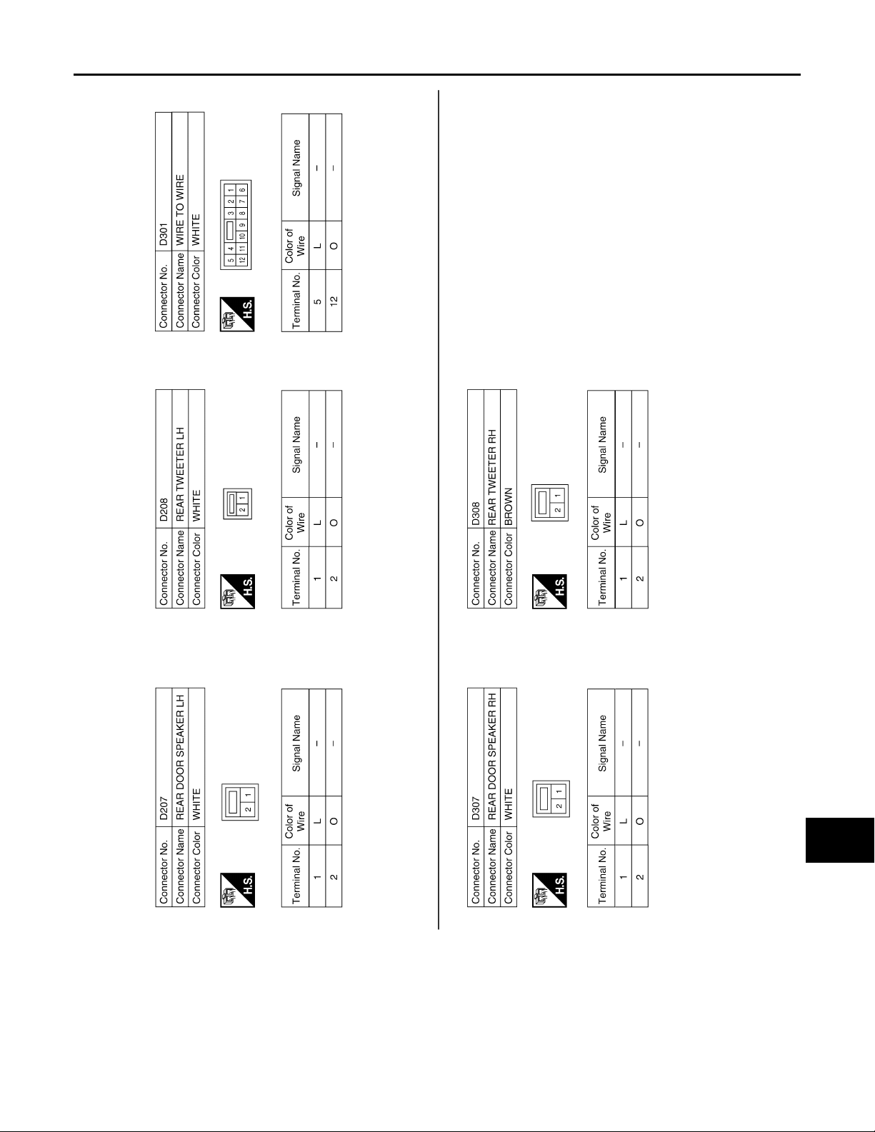
< ECU DIAGNOSIS >
AUDIO UNIT
[PREMIUM AUDIO]
A
B
C
D
E
F
G
AV
H
I
J
K
L
M
O
AV-91
@AMH@/46/FA
P
Page 97
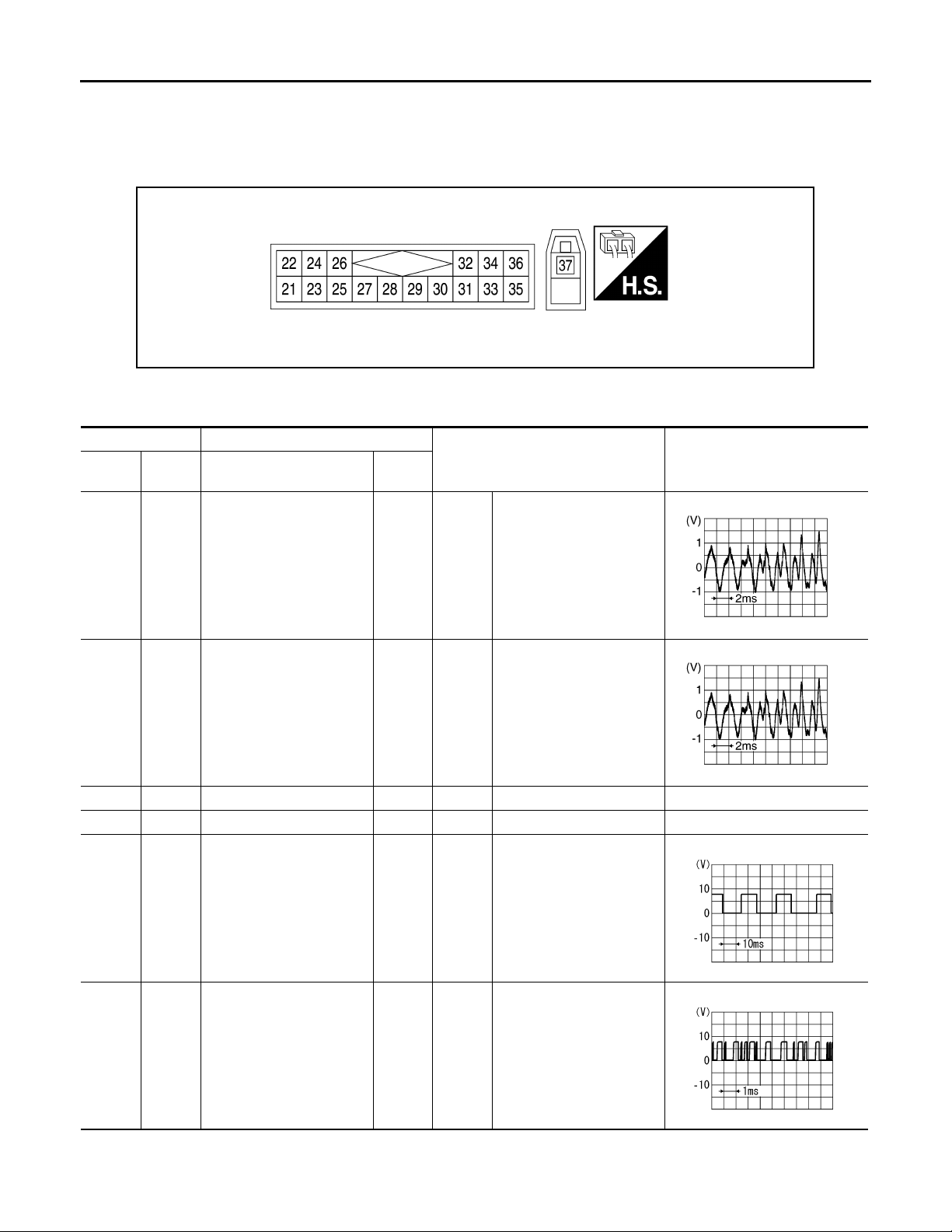
SATELLITE RADIO TUNER
< ECU DIAGNOSIS >
[PREMIUM AUDIO]
SATELLITE RADIO TUNER
Reference Value INFOID:0000000004095449
@VMH@0667YY
PHYSICAL VALUES
Te rm i n al D e sc r i pt i on
+– Signal name
22
(R)
24
(B)
25 — Shield — — — —
26 — Shield — — — —
21
(G)
23
(W)
Satellite radio sound signal
LH
Satellite radio sound signal
RH
Input/
Output
Output
Output
Ignition
switch
ON
Ignition
switch
ON
Condition
When satellite radio mode
is selected
When satellite radio mode
is selected
Reference value
(Approx.)
RJ HA25/ 8D
RJ HA25/ 8D
28
(O)
29
(P)
Ground
Ground
Request signal
(SAT→CONT)
Communication signal
(SAT→CONT)
Output
Output
Ignition
switch
ON
Ignition
switch
ON
AV-92
When satellite radio mode
is selected
RJ H@8188I
When satellite radio mode
is selected
RJ H@82/ / I
Page 98
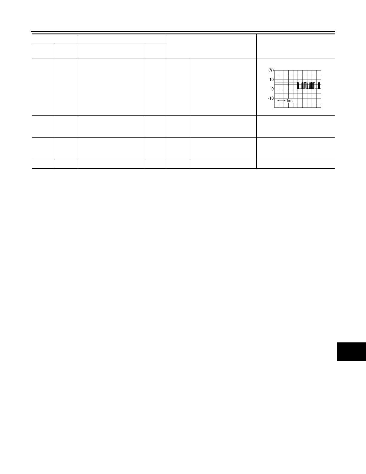
< ECU DIAGNOSIS >
SATELLITE RADIO TUNER
[PREMIUM AUDIO]
Te rm i n al D e sc r i pt i on
+– Signal name
30
Ground
(L)
32
(R/B)
(G/B)
Ground Battery power supply Input
36
Ground ACC power supply Input
37 — Satellite antenna Input — — —
Communication signal
(CONT→SAT)
Input/
Output
Input
Ignition
switch
ON
Ignition
switch
OFF
Ignition
switch
ACC
Condition
When satellite radio mode
is selected
—Battery voltage
—Battery voltage
Reference value
(Approx.)
A
B
C
RJ H@82/ 0I
D
E
F
G
H
AV
I
J
K
L
M
O
P
AV-93
Page 99
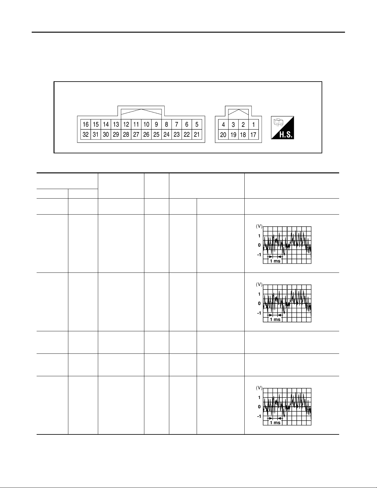
AUDIO AMP
< ECU DIAGNOSIS >
[PREMIUM AUDIO]
AUDIO AMP
Reference Value INFOID:0000000004095450
TERMINAL LAYOUT
@VMH@07/ 7YY
PHYSICAL VALUES
Te rm in al
(wire color)
+–
1
(Y)
2
(W)
3
(O)
4
(B)
9
(G/W)
Ground Battery Input – – Battery voltage
18
(G)
19
(BR)
Ground Ground –
Ground Amp. ON signal Input
Signal
Item
Subwoofer Output
Subwoofer Output
input/
output
Ignition
switch
ON
Ignition
switch
ON
Ignition
switch
ON
Ignition
switch
ON
Condition
Receive audio signal
Receive audio signal
––
–More than 6.5V
Reference value
(Approx.)
RJ H@/066D
RJ H@/066D
11
(G)
27
(B)
Rear door speaker LH and rear
door tweeter LH
Output
Ignition
switch
ON
AV-94
Receive audio signal
RJ H@/066D
Page 100
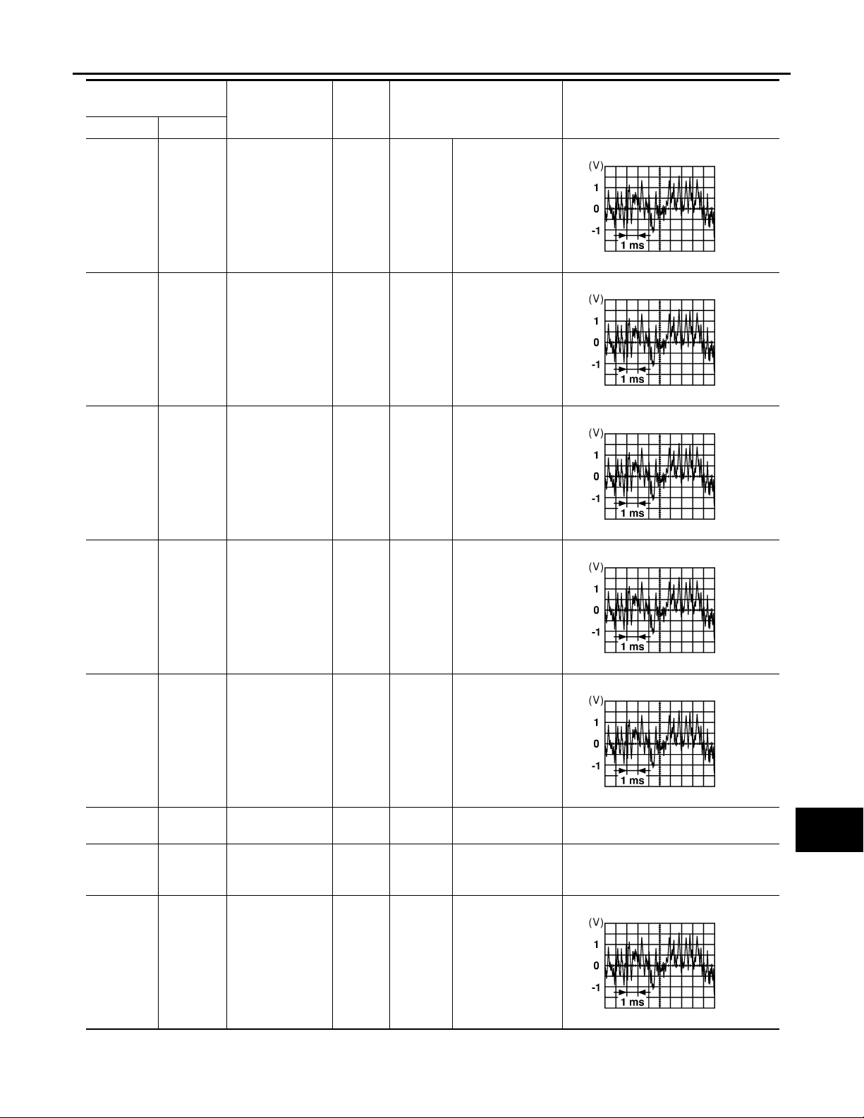
< ECU DIAGNOSIS >
AUDIO AMP
[PREMIUM AUDIO]
Te rm i n al
(wire color)
+–
12
(GR)
13
(W)
14
(Y)
28
(O)
29
(P)
30
(GR)
Signal
Item
Rear door speaker RH and rear
door tweeter RH
Front door tweeter RH
Front tweeter LH Output
input/
output
Output
Output
Ignition
switch
ON
Ignition
switch
ON
Ignition
switch
ON
Condition
Receive audio signal
Receive audio signal
Receive audio signal
Reference value
(Approx.)
RJ H@/066D
RJ H@/066D
A
B
C
D
E
F
G
H
15
(BR)
16
(LG)
17
(R/B)
20
(B)
31
(L)
32
(R)
Ground Battery Input – – Battery voltage
Ground Ground –
Front door speaker LH
Front door speaker RH
Output
Output
Ignition
switch
ON
Ignition
switch
ON
Ignition
switch
ON
Receive audio signal
Receive audio signal
––
RJ H@/066D
RJ H@/066D
RJ H@/066D
I
J
K
L
M
AV
O
21
(Y)
5
(BR)
Audio sound signal front RH
Input
Ignition
switch
ON
AV-95
Receive audio signal
P
RJ H@/066D
 Loading...