

Page 1
Edition: September 2005
Revision: September 2005
Publication No. SM6E-1N50U0
QUICK REFERENCE INDEX
A
GENERAL INFORMATION
B ENGINE
C
TRANSMISSION/
TRANSAXLE
D DRIVELINE/AXLE
E SUSPENSION
F BRAKES
G STEERING
H RESTRAINTS
I BODY
J AIR CONDITIONER
K ELECTRICAL
L MAINTENANCE
M INDEX
GI
General Information
EM
Engine Mechanical
LU
Engine Lubrication System
CO
Engine Cooling System
EC
Engine Control System
FL
Fuel System
EX
Exhaust System
ACC
Accelerator Control System
CL
Clutch
MT
Manual Transmission
AT
Automatic Transmission
TF
Transfer
PR
Propeller Shaft
FFD
Front Final Drive
RFD
Rear Final Drive
FAX
Front Axle
RAX
Rear Axle
FSU
Front Suspension
RSU
Rear Suspension
WT
Road Wheels & Tires
BR
Brake System
PB
Parking Brake System
BRC
Brake Control System
PS
Power Steering System
SB
Seat Belts
SRS
Supplemental Restraint System (SRS)
BL
Body, Lock & Security System
GW
Glasses, Window System & Mirrors
EI
Exterior & Interior
IP
Instrument Panel
SE
Seat
MTC
Manual Air Conditioner
SC
Starting & Charging System
LT
Lighting System
DI
Driver Information System
WW
Wiper, Washer & Horn
BCS
Body Control System
LAN
LAN System
AV
Audio Visual & Telephone System
ACS
Auto Cruise Control System
PG
Power Supply, Ground & Circuit Elements
MA
Maintenance
IDX
Alphabetical Index
A
B
C
D
E
F
G
H
I
J
K
L
M
© 2005 NISSAN NORTH AMERICA, INC.
All rights reserved. No part of this Service Manual may be reproduced or stored in a retrieval system, or transmitted in any
form, or by any means, electronic, mechanical, photo-copying, recording or otherwise, without the prior written permission
of Nissan North America, Inc., Gardena, California.
-1
Page 2
This manual contains maintenance and repair procedures for the
2006 NISSAN Xterra.
In order to assure your safety and the efficient functioning of the vehicle,
this manual should be read thoroughly. It is especially important that the
PRECAUTIONS in the GI section be completely understood before starting
any repair task.
All information in this manual is based on the latest product information
at the time of publication. The right is reserved to make changes in specifications and methods at any time without notice.
IMPORTANT SAFETY NOTICE
The proper performance of service is essential for both the safety of
the technician and the efficient functioning of the vehicle.
The service methods in this Service Manual are described in such a
manner that the service may be performed safely and accurately.
Service varies with the procedures used, the skills of the technician
and the tools and parts available. Accordingly, anyone using service
procedures, tools or parts which are not specifically recommended
by NISSAN must first be completely satisfied that neither personal
safety nor the vehicle’s safety will be jeopardized by the service
method selected.
-2
Page 3
PLEASE HELP MAKE THIS SERVICE MANUAL BETTER!
Your comments are important to NISSAN and will help us to improve our Service Manuals.
Use this form to report any issues or comments you may have regarding our Service Manuals.
Please print this form and type or write your comments below. Mail or fax to:
Nissan North America, Inc.
Technical Service Information
39001 Sunrise Drive, P.O. Box 9200
Farmington Hills, MI USA 48331
FAX: (248) 488-3910
SERVICE MANUAL: Model: Year:
PUBLICATION NO. (Refer to Quick Reference Index ):
Please describe any Service Manual issues or problems in detail:
Page number(s)
Note: Please include a copy of each page, marked with your comments.
Are the trouble diagnosis procedures logical and easy to use? (circle your answer) YES NO
If no, what page number(s)?
Please describe the issue or problem in detail:
Is the organization of the manual clear and easy to follow? (circle your answer) YES NO
Please comment:
What information should be included in NISSAN Service Manuals to better support you in servicing or
repairing customer vehicles?
Note: Please include a copy of each page, marked with your comments.
DATE: YOUR NAME: POSITION:
DEALER: DEALER NO.: ADDRESS:
CITY: STATE/PROV./COUNTRY: ZIP/POSTAL CODE:
Page 4
QUICK REFERENCE CHART: XTERRA
2006
QUICK REFERENCE CHART: XTERRA PFP:00000
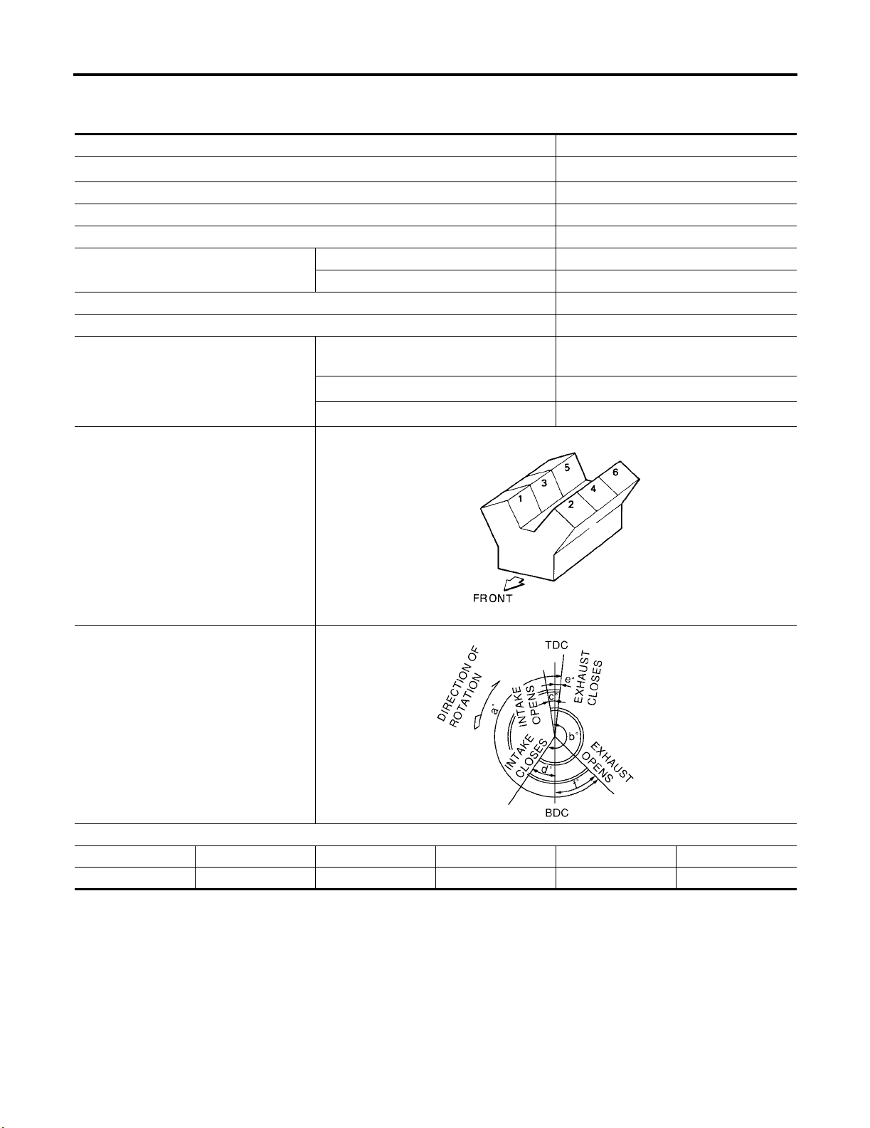
Engine Tune-Up Data
Cylinder arrangement V-6
Displacement
Bore and stroke 95.5 × 92.0 mm (3.76 × 3.622 in)
Valve arrangement DOHC
Firing order 1-2-3-4-5-6
Number of piston rings
Number of main bearings 4
Compression ratio 9.7:1
Compression pressure
Cylinder number
Compression 2
Oil 1
Standa rd
Minimum
Differential limit between cylinders
981 kPa (10.0 kg/cm
3,954 cm
1,275 kPa (13.0 kg/cm
98 kPa (1.0 kg/cm
3
(241.30 in3 )
2
, 185 psi) / 300
rpm
2
, 142 psi) / 300 rpm
2
, 14 psi) / 300 rpm
ELS001KR
SEM713A
Valve timing
(Intake valve timing control - “OFF”)
PBIC0187E
abcde f
244° 240°−4° 64° 6° 58°
Unit: degree
Page 5
QUICK REFERENCE CHART: XTERRA
Drive Belt Deflection and Tension
Tension of drive belt Auto adjustment by auto-tensioner
Spark Plugs (Double Platinum Tipped)
Make NGK
Standard type PLFR5A-11
Hot type PLFR4A-11
Cold type PLFR6A-11
Gap (nominal) 1.1 mm (0.043 in)
2006
Wheel Alignment (Unladen*1 )*6
Drive type 2WD 4WD
Minimum -0° 30′ (-0.50°)-0° 15′ (-0.25°)
Camber
Degree minute (decimal degree)
Caster
Degree minute (decimal degree)
Kingpin inclination
Degree minute (decimal degree)
Nominal 0° 15′ (0.25°)0° 30′ (0.50°)
Maximum 1° 0′ (1.00°)1° 15′ (1.25°)
Cross camber 0° 45′ (0.75°) or less 0° 45′ (0.75°) or less
Minimum 2° 15′ (2.25°)2° 0′ (2.00°)
Nominal 3° 0′ (3.00°)2° 45′ (2.75°)
Maximum 3° 45′ (3.75°)3° 30′ (3.50°)
Cross caster 0° 45′ (0.75°) or less 0° 45′ (0.75°) or less
Nominal 13° 0′ (13.00°)12° 45′ (12.75°)
ELS001KS
SFA234AC
Minimum 3.0 mm (0.12 in) 3.0 mm (0.12 in)
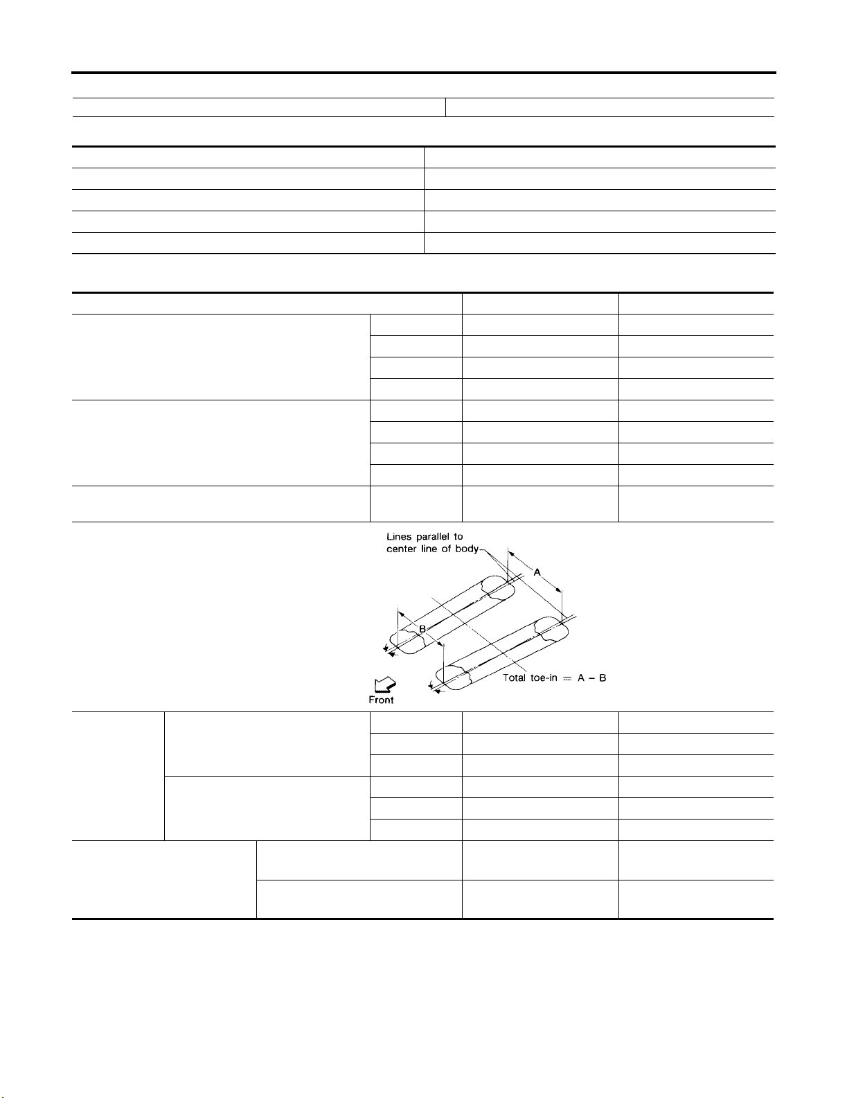
Distance (A − B)
To ta l t o e- i n
Angle (left wheel or right wheel)
Degree minute (decimal degree)
Inside
Degree minute (Decimal degree)
Wheel turning angle (full turn)
Outside
Degree minute (Decimal degree)
*1: Fuel, radiator coolant and engine oil full. Spare tire, jack, hand tools and mats in designated positions.
*2: Target value 35° 27′ (35.45°)
*3: Target value 31° 25′ (31.42°)
*4: Target value 35° 41′ (35.68°)
*5: Target value 31° 57′ (31.95°)
*6: Some vehicles may be equipped with straight (non-adjustable) lower link bolts and washers. In order to adjust camber and caster on
these vehicles, first replace the lower link bolts and washers with adjustable (cam) bolts and washers.
Nominal 4.0 mm (0.16 in) 4.0 mm (0.16 in)
Maximum 5.0 mm (0.20 in) 5.0 mm (0.20 in)
Minimum 0° 7′ (0.12°)0° 7′ (0.12°)
Nominal 0° 9′ (0.15°)0° 9′ (0.15°)
Maximum 0° 11′ (0.18°)0° 11′ (0.18°)
33° 27′ – 35° 27′ *
(33.45° – 35.45°)
29° 25′ – 31° 25′ *
(29.42° – 31.42°)
2
3
33° 41′ – 35° 41′ *
(33.68° – 35.68°)
29° 57′ – 31° 57′ *
(29.95° – 31.95°)
4
5
Page 6

QUICK REFERENCE CHART: XTERRA
2006
Brake
Front brake Brake model CLZ33VB
Rotor outer diameter × thickness 296 × 28 (11.654 × 1.102)
Pad Length × width × thickness 111.0 × 73.5 × 11.88 (4.73 × 2.894 × 0.468)
Cylinder bore diameter 51 (2.01)
Rear brake Brake model CLZ14VB
Rotor outer diameter × thickness 286 × 18.0 (11.260 × 0.709)
Pad Length × width × thickness 83.0 × 33.0 × 11.0 (3.268 × 1.299 × 0.433)
Cylinder bore diameter 38.1 (1.50)
Control valve Valve model Electric brake force distribution
Brake booster Booster model C215T
Diaphragm diameter 215 (8.46)
Recommended brake fluid
Genuine NISSAN Super Heavy Duty Brake Fluid or equivalent,
DOT 3 (US FMVSS No. 116)
Disc Brake - Repair Limits
FRONT DISC BRAKE
Brake model CLZ33VB
Brake pad
Disc rotor
Standa rd thickness (new) 11.88 (0.468)
Repair limit thickness 2.0 (0.079)
Standa rd thickness (new) 28. 0 (1.102)
Repair limit thickness 26.0 (1.024)
Maximum uneven wear (measured at 8 positions) 0.015 (0.0006)
Runout limit (with it attached to the vehicle) 0.05 (0.0020)
ELS001KU
Unit: mm (in)
ELS001KV
Unit: mm (in)
REAR DISC BRAKE
Brake model CLZ14VB
Brake pad
Disc rotor
Standa rd thickness (new) 11.0 mm (0.433 in)
Repair limit thickness 2.0 mm (0.079 in)
Standa rd thickness (new) 18.0 mm (0.709 in)
Repair limit thickness 16.0 mm (0.630 in)
Maximum uneven wear (measured at 8 positions) 0.015 mm (0.0006 in)
Runout limit (with it attached to the vehicle) 0.07 mm (0.0028 in)
Page 7
QUICK REFERENCE CHART: XTERRA
2006
Brake Pedal
ELS001KW
Unit: mm (in)
WFIA0160E
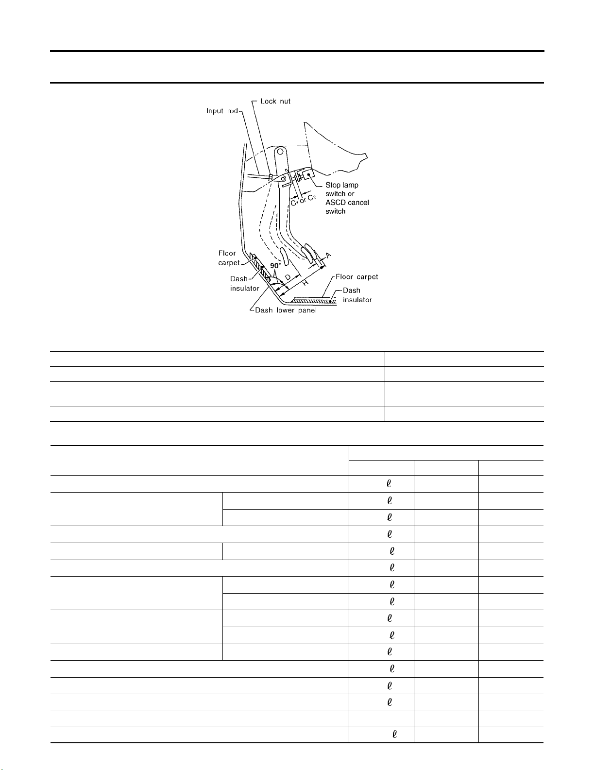
Free height "H" 182.1 - 192.1 (7.17 - 7.56)
Depressed pedal height ("D" [under a force of 490 N (50 kg, 110 lb) with engine running] 105 - 115 (4.13 - 4.53)
Clearance between pedal stopper and threaded end of stop lamp switch and ASCD switch
1 " or “C2 ”
"C
Pedal play "A" 3 - 11 (0.12 - 0.43)
0.74 - 1.96 (0.029 - 0.077)
Refill Capacities
Description
Fuel
Engine oil
Drain and refill
Dry engine (engine overhaul)
Cooling system With reservoir at MAX level
Automatic transmission fluid (ATF)
Manual transmission fluid (MTF)
(6 M/T model)
Rear final drive oil
Transfer fluid TX15B
Front final drive oil
Power steering fluid (PSF)
Windshield washer fluid
A/C system refrigerant 0.70 ± 0.05 kg 1.54 ± 0.11 lb 1.54 ± 0.11 lb
A/C system lubricant
With oil filter change
Without oil filter change
2WD
4WD
C200
M226
Metric US measure Imp measure
80
5.1
4.8
6.3
10.2
10.3
3.98
4.18
1.6
2.01
2.0
0.85
1.0
4.5
180 m
Capacity (Approximate)
21 1/8 gal 17 5/8 gal
5 3/8 qt 4 1/2 qt
5 1/8 qt 4 1/4 qt
6 5/8 qt 5 1/2 qt
2 3/4 gal 2 1/4 gal
10 7/8 qt 9 1/8 qt
8 3/8 pt 7 pt
8 7/8 pt 7 3/8 pt
3 3/8 pt 2 7/8 pt
4 1/4 pt 3 1/2 pt
2 1/8 qt 1 3/4 qt
1 3/4 pt 1 1/2 pt
2 1/8 pt 1 3/4 pt
1 1/4 gal 1 gal
6.1 fl oz 6.3 fl oz
ELS001KX
Page 8

K ELECTRICAL
A
B
SECTION WW
CONTENTS
PRECAUTION ............................................................ 3
Precautions for Supplemental Restraint System
(SRS) “AIR BAG” and “SEAT BELT PRE-TEN-
SIONER” .................................................................. 3
FRONT WIPER AND WASHER SYSTEM .................. 4
Components Parts and Harness Connector Loca-
tion ........................................................................... 4
System Description .................................................. 4
LOW SPEED WIPER OPERATION ...................... 5
HI SPEED WIPER OPERATION ........................... 5
INTERMITTENT OPERATION .............................. 5
AUTO STOP OPERATION .................................... 6
FRONT WASHER OPERATION ........................... 6
MIST OPERATION ................................................ 6
FAI L - SAFE F U N C TION .. ..... .... . .... ..... .................... 6
COMBINATION SWITCH READING FUNCTION ..... 7
CAN Communication System Description ................ 7
Schematic ................................................................ 8
Wiring Diagram — WIPER — .................................. 9
Ter mi na ls a nd R ef er en ce Va lu es f or B CM .. .. .. .. ..... 12
Ter mi na ls a nd R ef er en ce Va lu es f or I PD M E/R . .... 12
Work Flow .............................................................. 12
Preliminary Check .................................................. 12
INSPECTION FOR POWER SUPPLY AND
GROUND CIRCUIT ............................................. 12
CONSULT-II Function (IPDM E/R) ......................... 12
CONSULT-II OPERATION .................................. 12
DATA MONITOR ................................................. 13
ACTIVE TEST ..................................................... 13
CONSULT-II Function (BCM) ................................. 14
CONSULT-II OPERATION .................................. 14
WORK SUPPORT ............................................... 15
DATA MONITOR ................................................. 15
ACTIVE TEST ..................................................... 16
Trouble Diagnosis .................................................. 16
FRONT WIPER DOES NOT OPERATE ............. 16
FRONT WIPER STOP POSITION IS INCOR-
RECT .................................................................. 19
ONLY FRONT WIPER LOW DOES NOT OPER-
ATE ........ . ......... ... ...... . ........... .......... ......... ........... 20
WIPER, WASHER & HORN
ONLY FRONT WIPER HI DOES NOT OPERATE ... 22
ONLY FRONT WIPER INT DOES NOT OPER-
ATE ..... . ........... .......... ......... ......... . ......... ... ...... ...... 23
FRONT WIPER INTERMITTENT OPERATION
SWITCH POSITION CANNOT BE ADJUSTED ... 24
WIPERS DO NOT WIPE WHEN FRONT
WASHER OPERATES ........................................ 24
FRONT WIPERS OPERATE FOR 10 SECONDS,
STOP FOR 20 SECONDS, AND AFTER
REPEATING THIS OPERATION FIVE TIMES,
THEY BECOME INOPERATIVE ......................... 24
Removal and Installation ........................................ 26
FRONT WIPER ARMS ........................................ 26
WIPER MOTOR AND LINKAGE ......................... 27
WASHER NOZZLES ........................................... 28
WIPER AND WASHER SWITCH ........................ 28
WASHER FLUID RESERVOIR ........................... 29
FRONT AND REAR WASHER MOTOR .............. 30
WASHER FLUID LEVEL SENSOR ..................... 30
Washer Hose Layout .............................................. 31
Washer Nozzle Adjustment .................................... 31
REAR WIPER AND WASHER SYSTEM .................. 32
Components Parts and Harness Connector Loca-
tion .......................................................................... 32
System Description ................................................. 32
REAR WIPER OPERATION ................................ 32
INTERMITTENT OPERATION ............................ 32
AUTO STOP OPERATION .................................. 33
REAR WASHER OPERATION ............................ 33
BCM WIPER SWITCH READING FUNCTION .... 33
Wiring Diagram — WIP/R — .................................. 34
Ter min al s and R ef er en ce Va lu es f or B CM .. .. .. .. ...... 36
How to Proceed With Trouble Diagnosis ................ 36
Preliminary Check .................................................. 36
INSPECTION FOR POWER SUPPLY AND
GROUND CIRCUIT ............................................. 36
CONSULT-II Function (BCM) ................................. 36
CONSULT-II OPERATION ................................... 36
DATA MONITOR ................................................. 37
ACTIVE TEST ..................................................... 38
C
D
E
F
G
H
I
J
WW
L
M
Revision: September 2005 2006 Xterra
WW-1
Page 9

Rear Wiper Does Not Operate ............................... 38
Rear Wiper Stop Position Is Incorrect ..................... 40
Only Rear Wiper Does Not Operate ....................... 41
Only Rear Wiper Intermittent Does Not Operate .... 41
Wiper Does Not Wipe When Rear Washer Operates ... 42
Removal and Installation ........................................ 43
REAR WIPER ARM ............................................. 43
REAR WIPER ARM ADJUSTMENT .................... 43
REAR WIPER MOTOR ....................................... 44
REAR WASHER HOSE LAYOUT ........................ 45
REAR WASHER NOZZLE ................................... 46
REAR WASHER NOZZLE ADJUSTMENT .......... 46
FRONT AND REAR WASHER MOTOR .............. 47
WIPER AND WASHER SWITCH ........................ 47
WASHER FLUID RESERVOIR ........................... 47
POWER SOCKET .....................................................48
Wiring Diagram — P/SCKT — ................................48
Removal and Installation .........................................49
LOWER FRONT POWER SOCKET AND REAR
CARGO POWER SOCKET .................................49
UPPER FRONT POWER SOCKET (FOR CIGARETTE LIGHTER) AND CONSOLE POWER
SOCKET ..............................................................49
HORN ........................................................................50
Wiring Diagram — HORN — ..................................50
Removal and Installation .........................................51
HORN (SINGLE) ..................................................51
HORN (DUAL) .....................................................51
Revision: September 2005 2006 Xterra
WW-2
Page 10

PRECAUTION
PRECAUTION PFP:00011
Precautions for Supplemental Restraint System (SRS) “AIR BAG” and “SEAT
BELT PRE-TENSIONER”
EKS00DEF
A
The Supplemental Restraint System such as “AIR BAG” and “SEAT BELT PRE-TENSIONER”, used along
with a front seat belt, helps to reduce the risk or severity of injury to the driver and front passenger for certain
types of collision. This system includes seat belt switch inputs and dual stage front air bag modules. The SRS
system uses the seat belt switches to determine the front air bag deployment, and may only deploy one front
air bag, depending on the severity of a collision and whether the front occupants are belted or unbelted.
Information necessary to service the system safely is included in the SRS and SB section of this Service Manual.
WARNING:
● To avoid ren dering the SRS inoperativ e, w h ich cou ld increa se the risk o f perso nal injury or death
in the event of a collision which would result in air bag inflation, all maintenance must be performed by an authorized NISSAN/INFINITI dealer.
● Improper maintenance, including incorrect removal and installation of the SRS, can lead to per-
sonal injury caused by unintentional activation of the system. For removal of Spiral Cable and Air
Bag Module, see the SRS section.
● Do not use electrical test equipment on any circuit related to the SRS unless instructed to in this
Service Manual. SRS wiring harnesses can be identified by yellow and/or orange harnesses or
harness connectors.
B
C
D
E
F
G
H
I
J
WW
L
M
Revision: September 2005 2006 Xterra
WW-3
Page 11
FRONT WIPER AND WASHER SYSTEM
FRONT WIPER AND WASHER SYSTEM PFP:28810
Components Parts and Harness Connector Location EKS00HMG
WKIA5015E
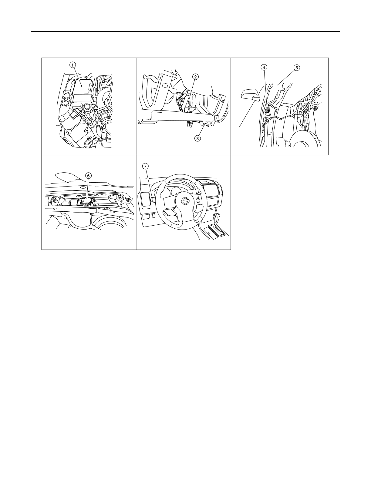
1. IPDM E/R
E121, E122, E124
4. Front and rear washer motor connector
E105
(view with front fender protector RH removed)
7. Combination switch
M28
2. BCM
M18, M20
(view with lower instrument panel LH removed)
5. Washer fluid reservoir 6. Front wiper motor
3. Data Link connector
E23
System Description EKS00DEI
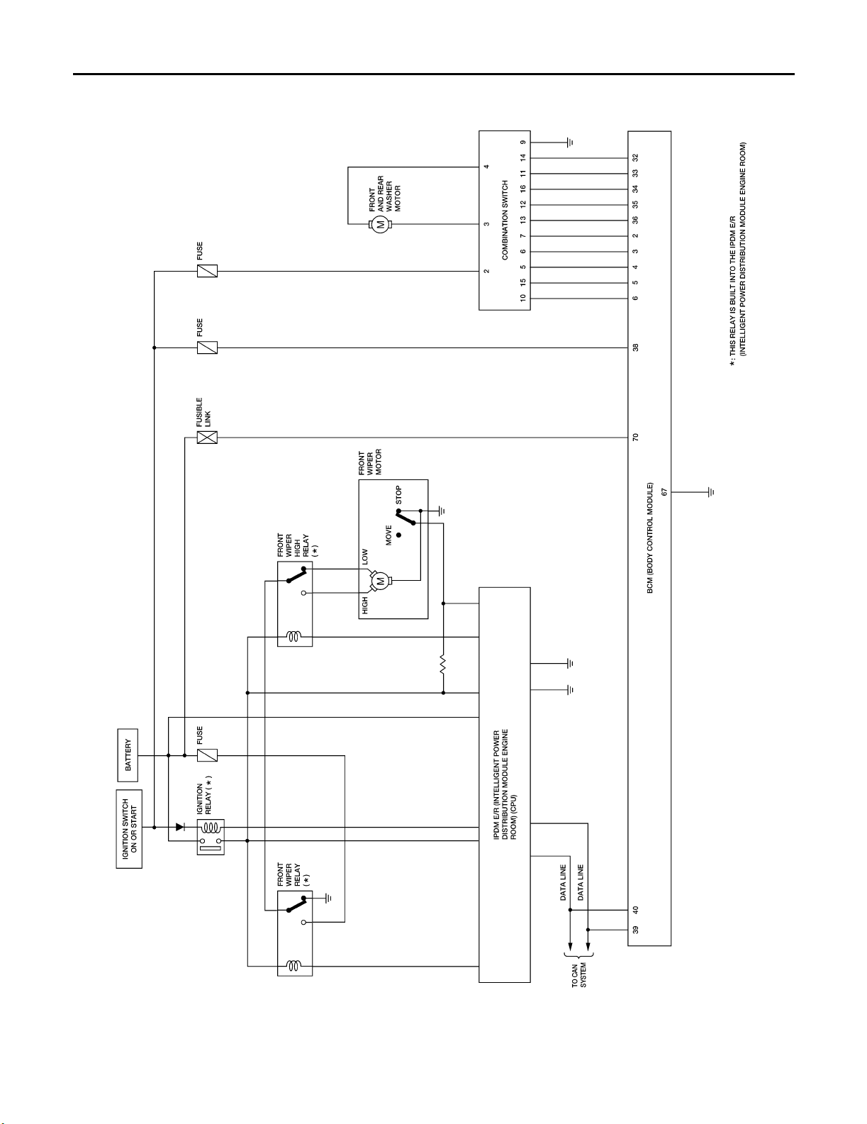
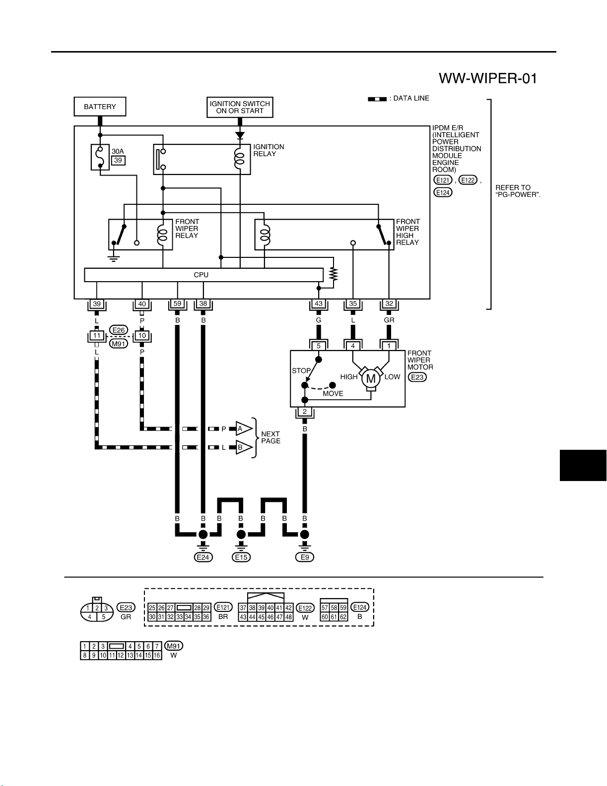
● Both front wiper relays are located in the IPDM E/R (intelligent power distribution module engine room).
● The wiper switch (combination switch) is composed of a combination of 5 output terminals and 5 input ter-
minals. Terminal combination status is read by the BCM (body control module) when the wiper switch is
turned ON.
● BCM controls front wiper LO, HI, and INT (intermittent) operation.
● IPDM E/R operates the wiper motor according to CAN communication signals from the BCM.
Power is supplied at all times
● to ignition relay, located in the IPDM E/R, and
● through 50A fusible link (letter g , located in the fuse and fusible link box)
● to BCM terminal 70, and
● through 30A fuse (No. 39, located in the IPDM E/R)
● to front wiper relay (located in the IPDM E/R).
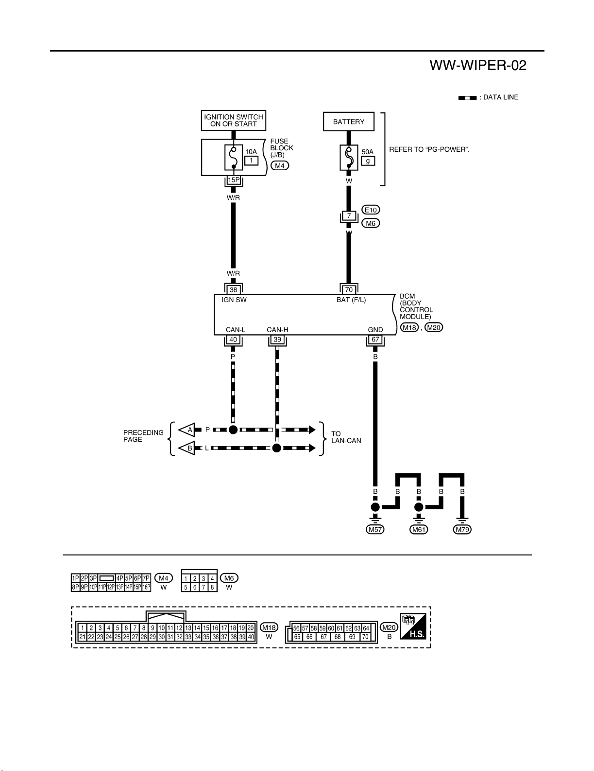
With the ignition switch in ON or START position, power is supplied
● to ignition relay, located in the IPDM E/R, and
● through 10A fuse [No. 15, located in the fuse block (J/B)]
Revision: September 2005 2006 Xterra
WW-4
Page 12

FRONT WIPER AND WASHER SYSTEM
● to combination switch terminal 2, and
● through 10A fuse [No. 1, located in the fuse block (J/B)]
● to BCM terminal 38.
Ground is supplied
● to BCM terminal 67 and
● to combination switch terminal 9
● through grounds M57, M61 and M79, and
● to IPDM E/R terminals 38 and 59 and
● to front wiper motor terminal 2
● through grounds E9, E15 and E24.
LOW SPEED WIPER OPERATION
When the ignition switch is in the ON or START position, and the front wiper switch is turned to the low position, the BCM detects a low speed wiper ON request through the combination switch (wiper switch) reading
function.
The BCM then sends a front wiper (low) request signal over CAN communication lines
● from BCM terminals 39 and 40
● to IPDM E/R terminals 39 and 40.
When IPDM E/R receives front wiper (low) request signal, it supplies ground to energize the front wiper relay.
With the front wiper relay energized, power is supplied
● through front wiper relay
● to front wiper high relay
● through IPDM E/R terminal 32
● to front wiper motor terminal 1.
With power and ground supplied, the front wiper motor operates at low speed.
HI SPEED WIPER OPERATION
When the ignition switch is in the ON or START position, and the front wiper switch is turned to the high position, the BCM detects a high speed wiper ON request through the combination switch (wiper switch) reading
function.
The BCM then sends a front wiper (high) request signal over CAN communication lines
● from BCM terminals 39 and 40
● to IPDM E/R terminals 39 and 40.
When the IPDM E/R receives a front wiper (high) request signal, it supplies ground to energize the front wiper
and the front wiper high relays.
With the front wiper and the front wiper high relays energized, power is supplied
● through front wiper relay
● to front wiper high relay
● through IPDM E/R terminal 35
● to front wiper motor terminal 4.
With power and ground supplied, the front wiper motor operates at high speed.
A
B
C
D
E
F
G
H
I
J
WW
L
M
INTERMITTENT OPERATION
Wiper intermittent operation delay interval is determined from the combination of the intermittent wiper dial
position inputs and vehicle speed. During each intermittent operation delay interval, the BCM sends a front
wiper request signal to the IPDM E/R to operate the wipers.
When the ignition switch is in the ON or START position, and the front wiper switch is turned to an intermittent
position, the BCM detects a front wiper (intermittent) ON request through the combination switch (wiper
switch) reading function.
The BCM then sends a front wiper (intermittent) request signal over CAN communication lines
● from BCM terminals 39 and 40
● to IPDM E/R terminals 39 and 40.
When the BCM determines that combination switch status is front wiper intermittent ON, it performs the following operations.
Revision: September 2005 2006 Xterra
WW-5
Page 13

FRONT WIPER AND WASHER SYSTEM
● BCM detects ON/OFF status of intermittent wiper dial position.
● BCM calculates operation interval from wiper dial position and vehicle speed signal received through CAN
communications.
● BCM sends front wiper request signal (INT) to IPDM E/R at calculated operation interval.
When the IPDM E/R receives a front wiper request signal (INT), it supplies ground to energize the front wiper
relay. It then sends an auto stop signal to the BCM, and conducts intermittent front wiper motor operation.
AUTO STOP OPERATION
When the wiper arms are not located at the base of the windshield, and the wiper switch is turned OFF, the
wiper motor will continue to operate until the wiper arms reach the windshield base. When the wiper arms
reach the base of windshield, front wiper motor terminals 5 and 2 are connected.
Ground is supplied
● to IPDM E/R terminal 43
● through front wiper motor terminal 5
● through front wiper motor terminal 2
● through grounds E9, E15 and E24.
The IPDM E/R sends an auto stop operation signal to the BCM through CAN communication lines.
When the BCM receives an auto stop operation signal, the BCM sends wiper stop signal to the IPDM E/R over
CAN communication lines. The IPDM E/R then de-energizes the front wiper relay.
The wiper motor will then stop the wiper arms at the STOP position.
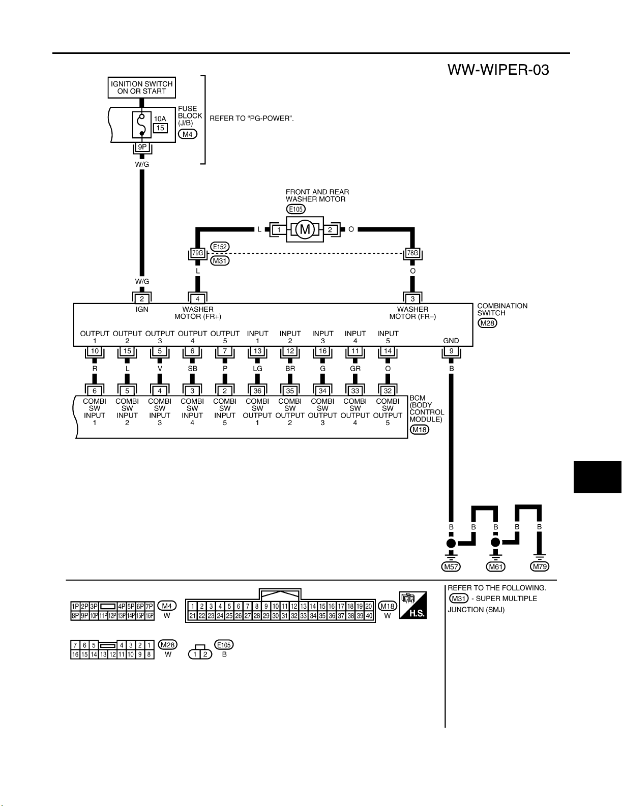
FRONT WASHER OPERATION
When the ignition switch is in the ON or START position, and the front and rear washer switches are OFF, the
front and rear washer motor is supplied power
● through 10A fuse [No. 15, located in the fuse block (J/B)]
● through combination switch (wiper switch) terminal 2
● through combination switch (wiper switch) terminal 4
● to front and rear washer motor terminal 1.
When the front wiper switch is in the front washer position, the BCM detects a front washer signal request
through the combination switch (wiper switch) reading function.
Combination switch ground is supplied
● to front and rear washer motor terminal 2
● through combination switch (wiper switch) terminal 3
● through combination switch (wiper switch) terminal 9
● through grounds M57, M61 and M79.
With ground supplied, the front and rear washer motor is operated in the front direction.
When the BCM detects that front washer motor has operated for 0.4 seconds or longer, the BCM uses CAN
communication and sends a wiper request signal to the IPDM E/R for low speed operation of wipers.
When the BCM detects that the washer switch is OFF, low speed operation cycles approximately 3 times and
then stops.
MIST OPERATION
When the wiper switch is temporarily placed in the mist position, wiper low speed operation cycles once and
then stops.
For additional information about wiper operation under this condition, refer to WW-5, "
LOW SPEED WIPER
OPERATION" .
If the switch is held in the mist position, low speed operation continues.
FAIL-SAFE FUNCTION
The BCM includes fail-safe function to prevent malfunction of electrical components controlled by CAN communications if a malfunction in CAN communications occurs.
The BCM uses CAN communications to stop output of electrical components it controls.
Until the ignition switch is turned OFF, the front wiper system remains in same status as just before fail-safe
control was initiated. (If wiper was in low speed operation just before fail-safe, it continues low speed operation
until ignition switch is turned OFF.)
When fail-safe status is initiated, the BCM remains in standby until normal signals are received.
When normal signals are received, fail-safe status is canceled.
Revision: September 2005 2006 Xterra
WW-6
Page 14

FRONT WIPER AND WASHER SYSTEM
COMBINATION SWITCH READING FUNCTION
Refer to BCS-3, "COMBINATION SWITCH READING FUNCTION" .
CAN Communication System Description EK S0 0DEJ
A
Refer to LAN-21, "CAN COMMUNICATION" .
B
C
D
E
F
G
H
I
J
WW
L
M
Revision: September 2005 2006 Xterra
WW-7
Page 15
FRONT WIPER AND WASHER SYSTEM
Schematic EKS00DEK
WKWA2463E
Revision: September 2005 2006 Xterra
WW-8
Page 16
FRONT WIPER AND WASHER SYSTEM
Wiring Diagram — WIPER — EKS00DEL
A
B
C
D
E
F
G
H
I
J
WW
L
M
WKWA2464E
Revision: September 2005 2006 Xterra
WW-9
Page 17
FRONT WIPER AND WASHER SYSTEM
WKWA4335E
Revision: September 2005 2006 Xterra
WW-10
Page 18
FRONT WIPER AND WASHER SYSTEM
A
B
C
D
E
F
G
H
I
J
WW
L
M
WKWA4336E
Revision: September 2005 2006 Xterra
WW-11
Page 19
FRONT WIPER AND WASHER SYSTEM
Terminals a nd Ref er ence Values for B CM EKS00HMH
Refer to BCS-12, "Ter min al s an d Re fe re nce Va lu es fo r BC M" .
Terminals a nd Ref er ence Values for I PD M E/R EKS00DEN
Refer to PG-29, "Ter mi na ls a nd R ef er en ce Va lu es f or IP DM E /R " .
Work Flow EKS0 0DEO
1. Confirm the symptom or customer complaint.
2. Understand the system description, refer to WW-4, "System Description" .
3. Perform preliminary inspection, refer to WW-12, "
4. Check symptom and repair or replace the cause of malfunction.
5. Does wiper function operate normally? If it operates normally, GO TO 6. If not, GO TO 4.
6. Inspection End.
Preliminary Check" .
Preliminary Check EKS00DEP
INSPECTION FOR POWER SUPPLY AND GROUND CIRCUIT
Refer to BCS-16, "BCM Power Supply and Ground Circuit Check" and PG-31, "IPDM E/R Power/Ground Cir-
cuit Inspection" .
CONSULT-II Function (IPDM E/R) EKS00DER
CONSULT-II can display each diagnostic item using the diagnostic test modes shown following.
IPDM E/R diagnostic Mode Description
SELF-DIAG RESULTS Displays IPDM E/R self-diagnosis results.
DATA MONITOR Displays IPDM E/R input/output data in real time.
CAN DIAG SUPPORT MNTR The result of transmit/receive diagnosis of CAN communication can be read.
ACTIVE TEST Operation of electrical loads can be checked by sending drive signal to them.
CONSULT-II OPERATION
CAUTION:
If CONSULT-II is used with no connection of CONSULT-II CONVERTER, malfunctions might be
detected in self-diagnosis depending on control unit which carries out CAN communication.
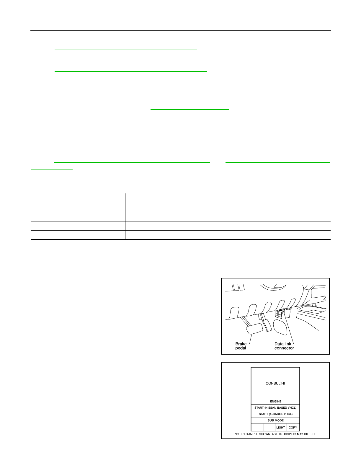
1. With the ignition switch OFF, connect CONSULT-II and CON-
SULT-II CONVERTER to the data link connector, then turn the
ignition switch ON.
BBIA 0538E
2. Touch "START (NISSAN BASED VHCL)".
BCIA0 029E
Revision: September 2005 2006 Xterra
WW-12
Page 20
FRONT WIPER AND WASHER SYSTEM
3. Touch "IPDM E/R" on "SELECT SYSTEM" screen.
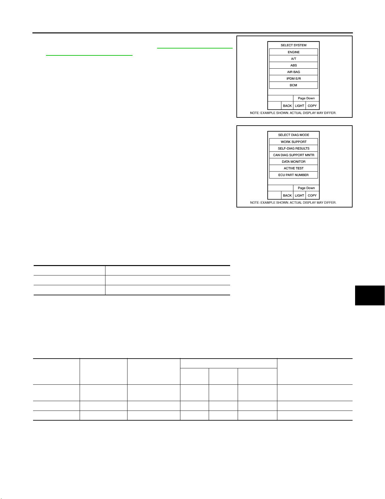
If "IPDM E/R" is not displayed, go to GI-41, "
Link Connector (DLC) Circuit" .
4. Select the desired part to be diagnosed on the "SELECT DIAG
MODE" screen.
CONSULT-II Data
A
B
C
BCIA0 030E
D
E
F
G
BCIA0 031E
DATA MONITOR
Operation Procedure
1. Touch "DATA MONITOR" on the "SELECT DIAG MODE" screen.
2. Touch "ALL SIGNALS", "MAIN SIGNALS" or "SELECTION FROM MENU" on the "SELECT MONITOR
ITEM" screen.
ALL SIGNALS Monitors all the items.
MAIN SIGNALS Monitors predetermined items.
SELECTION FROM MENU Selects and monitors the individual item selected.
3. Touch "START".
4. When "SELECTION FROM MENU" is selected, touch items to be monitored. When "ALL SIGNALS" is
selected, all the items will be monitored. When "MAIN SIGNALS" is selected, predetermined items are
monitored.
5. Touch "RECORD" while monitoring to record the status of the item being monitored. To stop recording,
touch "STOP".
All Signals, Main Signals, Selection From Menu
Item name
Front wiper
request
Wiper auto stop WIP AUTO STOP ACT P/STOP P x x x Output status of IPDM E/R.
Wiper protection WIP PROT OFF/LS/HS/BLOCK x x x Control status of IPDM E/R.
CONSULT-II
screen display
FR WIP REQ STOP/1LO/LO/HI x x x Signal status input from BCM.
Display or unit
SIGNALS
Monitor item selection
ALL
MAIN
SIGNALS
SELECTION
FROM MENU
Description
H
I
J
WW
L
M
NOTE:
Perform monitoring of IPDM E/R data with the ignition switch ON. When the ignition switch is at ACC, the display may not be correct.
ACTIVE TEST
Operation Procedure
1. Touch "ACTIVE TEST" on the "SELECT DIAG MODE" screen.
Revision: September 2005 2006 Xterra
WW-13
Page 21
FRONT WIPER AND WASHER SYSTEM
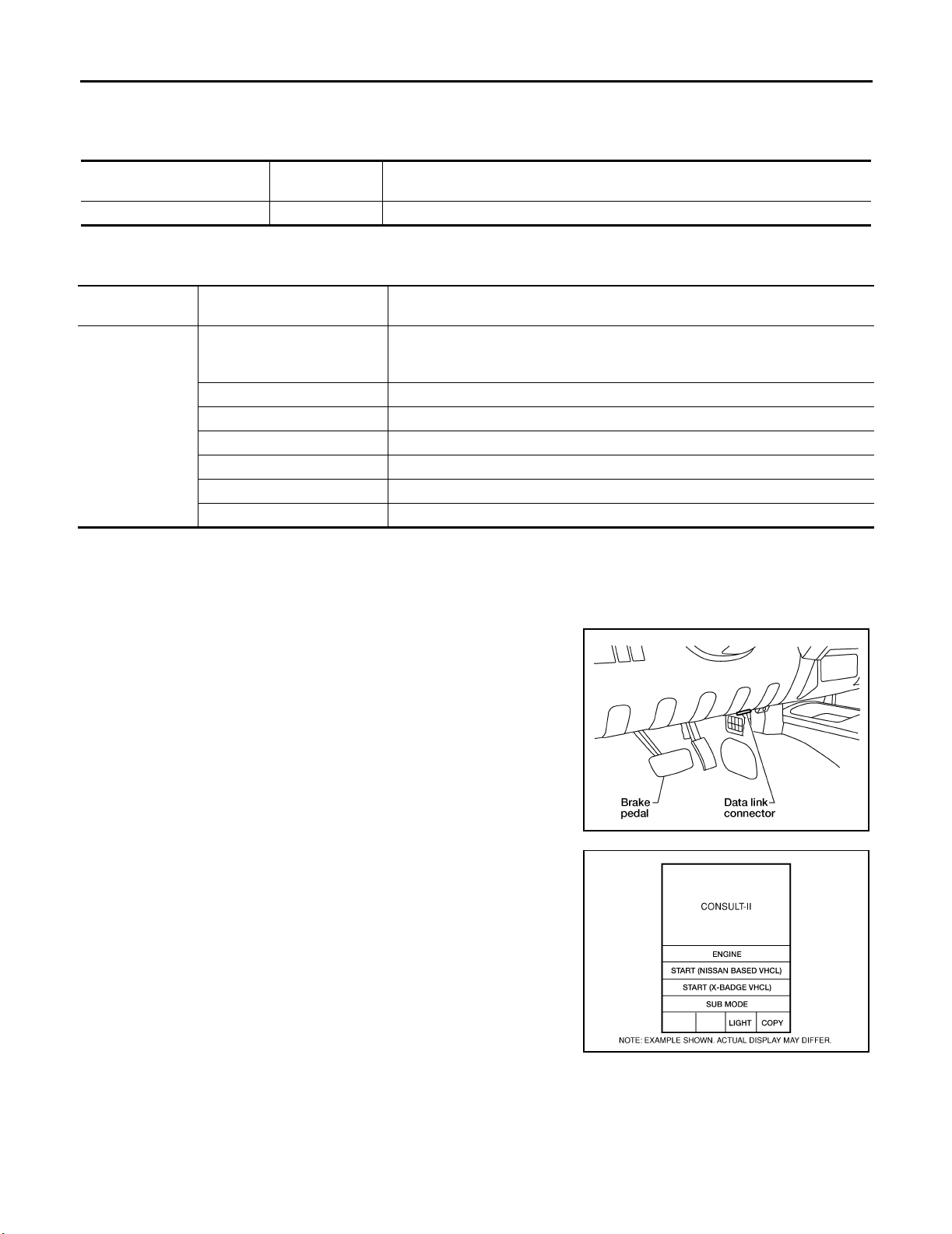
2. Touch item(s) to be tested and check operation of the selected item(s).
3. During the operation check, touching "BACK" deactivates the operation.
Display Item List
Te s t i t e m
Front wiper (HI, LO) output FRONT WIPER With a certain operation (OFF, HI, LO) front wiper relays can be operated.
CONSULT-II
screen display
Description
CONSULT-II Function (BCM) EKS 00H MI
CONSULT-II can display each diagnostic item using the diagnostic test modes shown following.
BCM diagnostic
test item
Inspection by part
Diagnostic mode Description
Supports inspections and adjustments. Commands are transmitted to the BCM
WORK SUPPORT
DATA MONITOR Displays BCM input/output data in real time.
ACTIVE TEST Operation of electrical loads can be checked by sending drive signal to them.
SELF-DIAG RESULTS Displays BCM self-diagnosis results.
CAN DIAG SUPPORT MNTR The result of transmit/receive diagnosis of CAN communication can be read.
ECU PART NUMBER BCM part number can be read.
CONFIGURATION Performs BCM configuration read/write functions.
for setting the status suitable for required operation, input/output signals are
received from the BCM and received data is displayed.
CONSULT-II OPERATION
CAUTION:
If CONSULT-II is used with no connection of CONSULT-II CONVERTER, malfunctions might be
detected in self-diagnosis depending on control unit which carries out CAN communication.
1. With the ignition switch OFF, connect CONSULT-II and CONSULT-II CONVERTER to the data link connector, then turn the
ignition switch ON.
BBIA 0538E
2. Touch "START (NISSAN BASED VHCL)".
BCIA0 029E
3. Touch "BCM" on the "SELECT SYSTEM" screen.
Revision: September 2005 2006 Xterra
WW-14
Page 22
FRONT WIPER AND WASHER SYSTEM
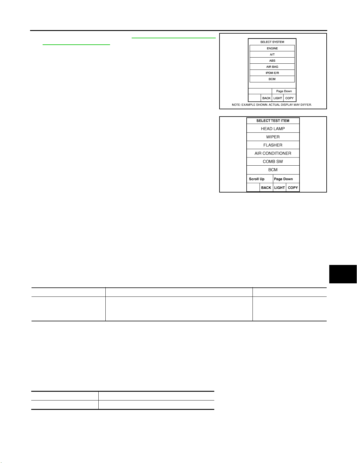
If "BCM" is not indicated, go to GI-41, "CONSULT-II Data Link
Connector (DLC) Circuit" .
4. Select the desired part to be diagnosed on the "SELECT TEST
ITEM" screen.
A
B
C
BCIA0 030E
D
E
F
G
LKIA01 83E
WORK SUPPORT
Operation Procedure
1. Touch "WIPER" on the "SELECT TEST ITEM" screen.
2. Touch "WORK SUPPORT" on the "SELECT DIAG MODE" screen.
3. Touch "WIPER SPEED SETTING" on the "SELECT WORK ITEM" screen.
4. Touch "START".
5. Touch "CHANGE SETT".
6. The setting will be changed and "CURRENT SETTING" will be displayed.
7. Touch "END".
Work Support Setting Item
Item Description CONSULT-II
When wiper switch is at INTERMITTENT, front wiper intermittent
WIPER SPEED SETTING
NOTE:
Factory setting
time can be selected according to vehicle speed.
● ON (Operated)/OFF
NOTE
(Not operated)
ON/OFF
DATA MONITOR
Operation Procedure
1. Touch "WIPER" on the "SELECT TEST ITEM" screen.
2. Touch "DATA MONITOR" on the "SELECT DIAG MODE" screen.
3. Touch either "ALL SIGNALS" or "SELECTION FROM MENU" on the "SELECT MONITOR ITEM" screen.
H
I
J
WW
L
M
ALL SIGNALS Monitors all the items.
SELECTION FROM MENU Selects and monitors the individual item selected.
4. Touch "START".
5. When "SELECTION FROM MENU" is selected, touch items to be monitored. When "ALL SIGNALS" is
selected, all the items will be monitored.
Revision: September 2005 2006 Xterra
WW-15
Page 23
FRONT WIPER AND WASHER SYSTEM
6. Touch "RECORD" while monitoring to record the status of the item being monitored. To stop recording,
touch "STOP".
Display Item List
Monitor item name
"OPERATION OR UNIT"
IGN ON SW "ON/OFF" Displays "IGN Position (ON)/OFF, ACC Position (OFF)" status as judged from ignition switch signal.
IGN SW CAN "ON/OFF"
FR WIPER HI "ON/OFF" Displays "Front Wiper HI (ON)/Other (OFF)" status as judged from wiper switch signal.
FR WIPER LOW "ON/OFF" Displays "Front Wiper LOW (ON)/Other (OFF)" status as judged from wiper switch signal.
FR WIPER INT "ON/OFF" Displays "Front Wiper INT (ON)/Other (OFF)" status as judged from wiper switch signal.
FR WASHER SW "ON/OFF" Displays "Front Washer Switch (ON)/Other (OFF)" status as judged from wiper switch signal.
INT VOLUME (1 - 7) Displays intermittent operation dial position setting (1 - 7) as judged from wiper switch signal.
FR WIPER STOP "ON/OFF" Displays "Stopped (ON)/Operating (OFF)" status as judged from the auto stop signal.
VEHICLE SPEED "0.0 km/h" Displays vehicle speed as received from CAN communication.
Displays "IGN switch ON (ON)/Other OFF or ACC (OFF)" status as judged from CAN communications.
ACTIVE TEST
Operation Procedure
1. Touch "WIPER" on the "SELECT TEST ITEM" screen.
2. Touch "ACTIVE TEST" on the "SELECT DIAG MODE" screen.
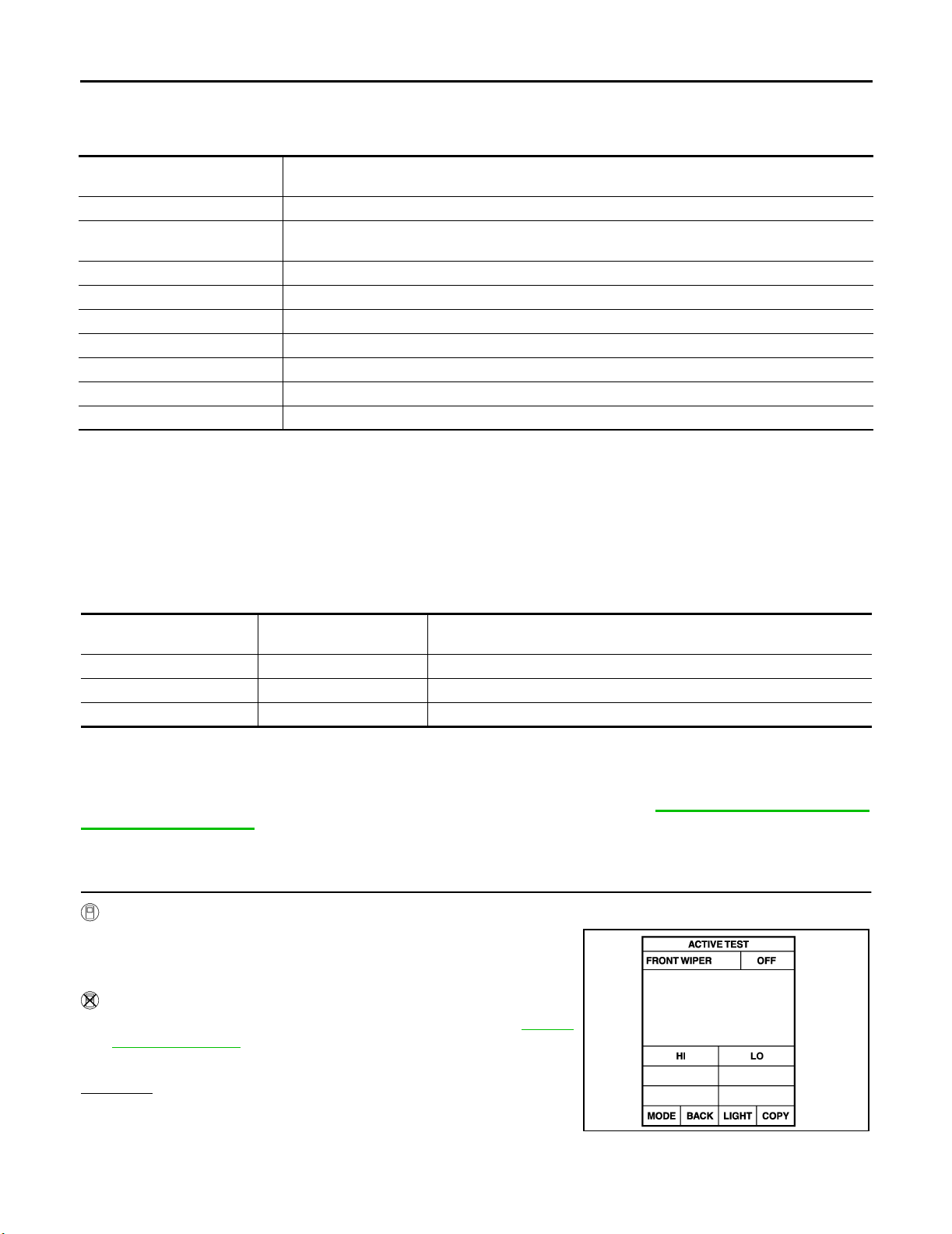
3. Touch item(s) to be tested and check operation of the selected item(s).
4. During the operation check, touching "BACK" deactivates the operation.
Contents
Display Item List
Tes t it em
Front wiper HI output FR WIPER (HI) Front wiper HI can be operated by any ON-OFF operation.
Front wiper LO output FR WIPER (LO) Front wiper LO can be operated by any ON-OFF operation.
Front wiper INT output FR WIPER (INT) Front wiper INT can be operated by any ON-OFF operation.
Display on CONSULT-II
screen
Description
Trouble Diagnosis EKS00DES
FRONT WIPER DOES NOT OPERATE
CAUTION:
During IPDM E/R fail-safe control, front wipers may not operate. Refer to PG-18, "
CAN COMMUNICA-
TION LINE CONTROL" to make sure that it is not in fail-safe status.
Inspection Procedure
1. CHECK IPDM E/R TO FRONT WIPERS
With CONSULT-II
1. Select "IPDM E/R" with CONSULT-II, and select "ACTIVE
TEST" on "SELECT DIAG MODE" screen.
2. Select "FRONT WIPER" on "SELECT TEST ITEM" screen.
Without CONSULT-II
1. Turn on front wipers using auto active test. Refer to PG-24,
"Auto Active Test" .
2. Confirm front wiper operation.
OK or NG
OK >> GO TO 4.
NG >> GO TO 2.
SKIA 3486E
Revision: September 2005 2006 Xterra
WW-16
Page 24
FRONT WIPER AND WASHER SYSTEM
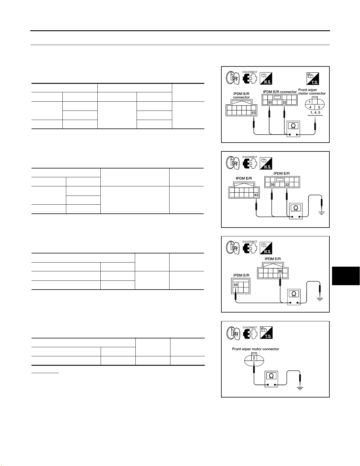
2. IPDM E/R TO FRONT WIPERS CONTINUITY INSPECTION
1. Turn ignition switch OFF.
2. Disconnect IPDM E/R connectors and front wiper motor connector.
3. Check continuity between IPDM E/R harness connector terminals and front wiper motor harness connector terminals.
IPDM E/R Front wiper motor
Connector Terminal Connector Terminal
E121
E122 43 5
32
E23
1
4. Check continuity between IPDM E/R harness connector terminals and ground.
IPDM E/R
Connector Terminal
E121
E122 43
32
Ground No35
Continuity
Ye s35 4
Continuity
WKIA3193E
A
B
C
D
E
F
G
H
5. Check continuity between IPDM E/R harness connector terminal
and ground.
IPDM E/R
Connector Terminal
E122 38
E124 59
Ground Yes
Continuity
6. Check continuity between front wiper motor harness connector
E23 terminal 2 and ground.
Front wiper motor
Connector Terminal
E23 2 Ground Yes
Continuity
OK or NG
OK >> Connect connectors. GO TO 3.
NG >> Repair harness or connector.
WKIA1424E
I
J
WW
L
WKIA1425E
M
WKIA3194E
Revision: September 2005 2006 Xterra
WW-17
Page 25
FRONT WIPER AND WASHER SYSTEM
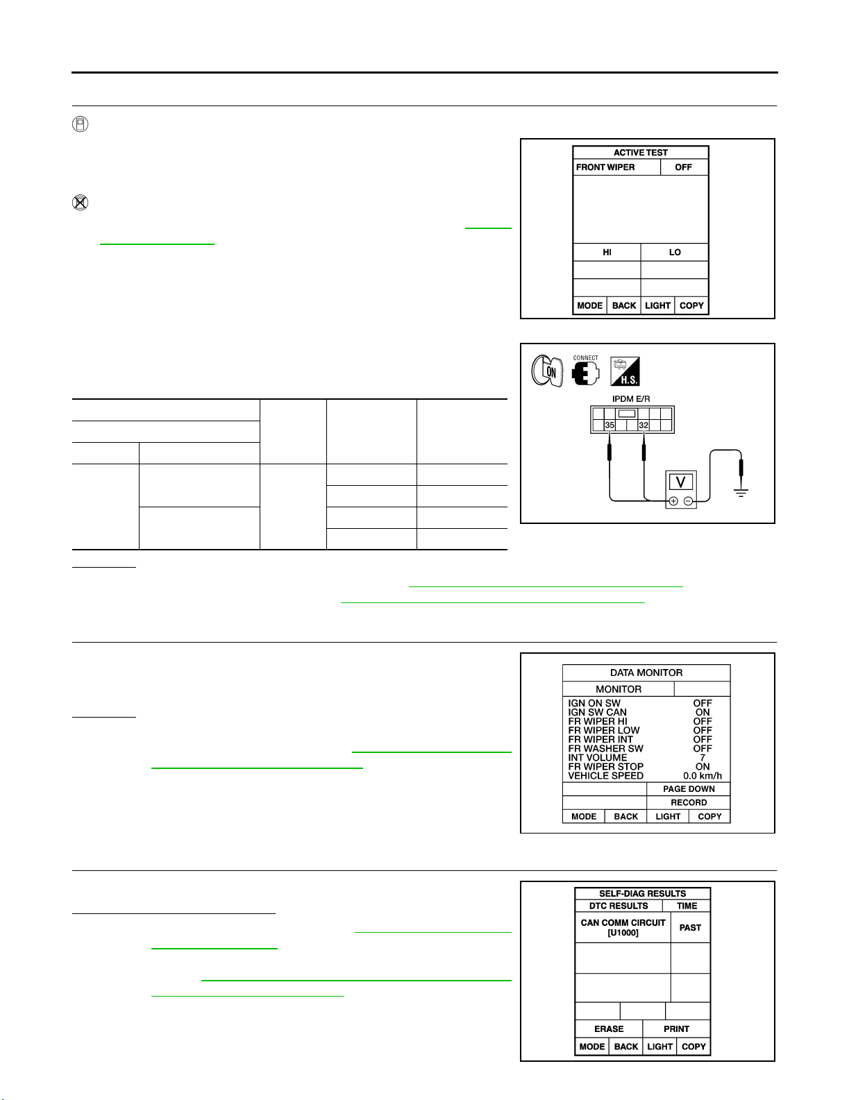
3. IPDM E/R INSPECTION
With CONSULT-II
1. Select "IPDM E/R" with CONSULT-II, and select "ACTIVE
TEST" on "SELECT DIAG MODE" screen.
2. Select "FRONT WIPER" on "SELECT TEST ITEM" screen.
Without CONSULT-II
1. Turn on front wipers using the auto active test. Refer to PG-24,
"Auto Active Test" .
When front wiper relay, and front wiper high relay are operating,
check voltage between IPDM E/R harness connector E121 terminals
32, 35 and ground.
IPDM E/R
(+)
Connector Terminal
32
E121
35
(–) Condition
Stopped 0
Ground
LO operation Battery voltage
Stopped 0
HI operation Battery voltage
OK or NG
OK >> Replace the front wiper motor. Refer to WW-27, "WIPER MOTOR AND LINKAGE" .
NG >> Replace IPDM E/R. Refer to PG-33, "
Removal and Installation of IPDM E/R" .
Voltage
(Approx.)
SKIA 3486E
WKIA1427E
4. CHECK COMBINATION SWITCH TO BCM
Select "BCM" on CONSULT-II. With "WIPER" data monitor, check
that "FR WIPER INT", "FR WIPER LOW" and "FR WIPER HI" turn
ON-OFF according to operation of wiper switch.
OK or NG
OK >> GO TO 5.
NG >> Check wiper switch. Refer to BCS-3, "
COMBINATION
SWITCH READING FUNCTION" .
5. COMBINATION SWITCH TO BCM CONTINUITY INSPECTION
Select "BCM" on CONSULT-II. Carry out self-diagnosis of BCM.
Displayed self-diagnosis results
NO DTC>> Replace the BCM. Refer to BCS-26, "Removal and
Installation of BCM" .
CAN COMM CIRCUIT>> Check CAN communication line of BCM.
GO TO BCS-19, "
CONSULT-II (Self-Diagnosis)" .
CAN Communication Inspection Using
WKIA1018E
SKIA 1039E
Revision: September 2005 2006 Xterra
WW-18
Page 26
FRONT WIPER AND WASHER SYSTEM
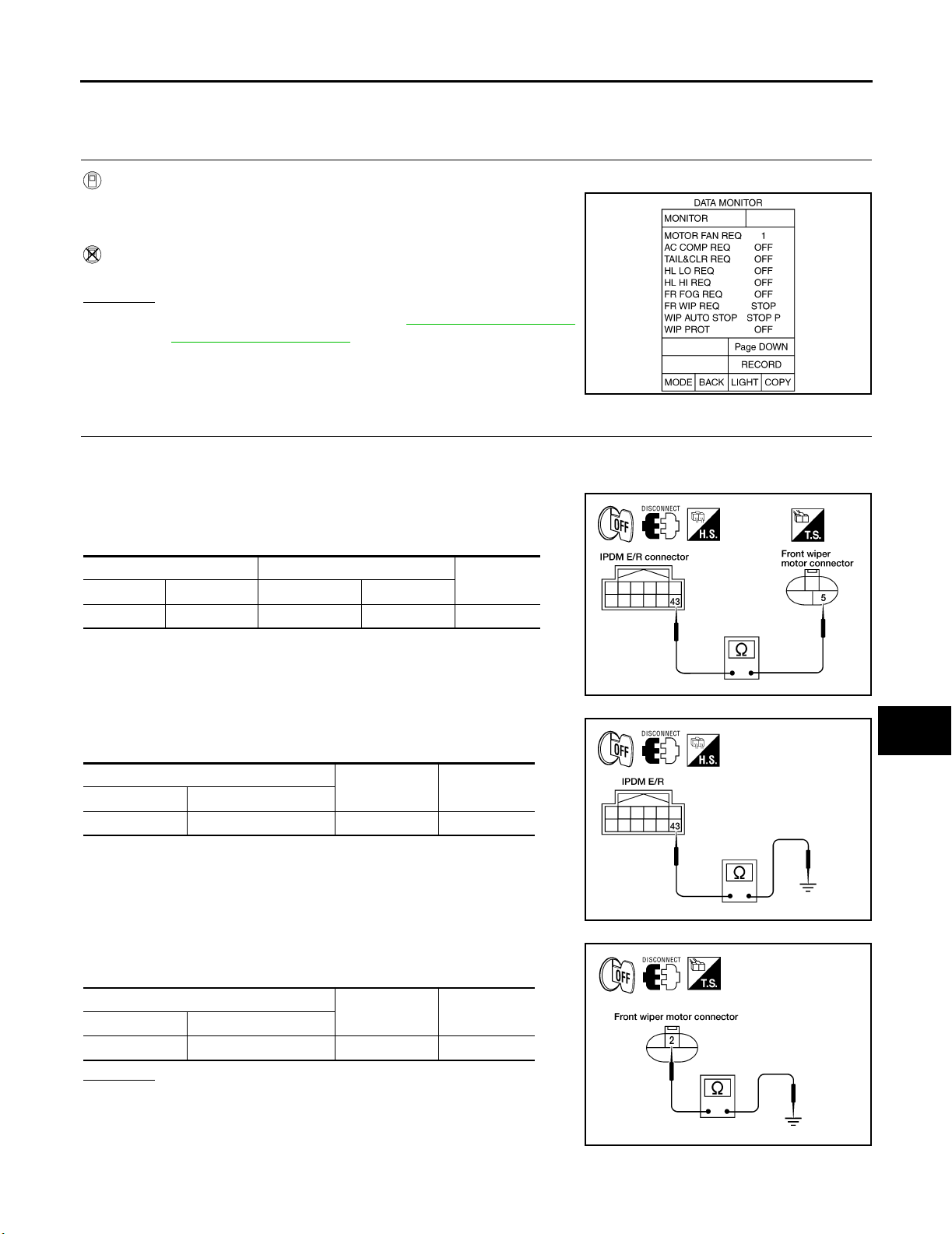
FRONT WIPER STOP POSITION IS INCORRECT
Inspection Procedure
1. CHECK IPDM E/R TO FRONT WIPER MOTOR
A
With CONSULT-II
Select "IPDM E/R" with CONSULT-II. With data monitor, confirm that
"WIP AUTO STOP" changes from "ACT P" to "STOP P" according to
wiper operation.
Without CONSULT-II
GO TO 2.
OK or NG
OK >> Replace IPDM E/R. Refer to PG-33, "Removal and
Installation of IPDM E/R" .
NG >> GO TO 2.
2. IPDM E/R TO FRONT WIPER MOTOR CONTINUITY INSPECTION
1. Turn ignition switch OFF.
2. Disconnect IPDM E/R connector and front wiper motor connector.
3. Check continuity between IPDM E/R harness connector E122
terminal 43 and front wiper motor harness connector E23 terminal 5.
IPDM E/R Front wiper motor
Connector Terminal Connector Terminal
E122 43 E23 5 Yes
Continuity
B
C
D
E
SKIA 5301E
F
G
H
I
4. Check continuity between IPDM E/R harness connector E122
terminal 43 and ground.
IPDM E/R
Connector Terminal
E122 43 Ground No
Continuity
5. Check continuity between front wiper motor harness connector
E23 terminal 2 and ground.
Front wiper motor
Connector Terminal
E23 2 Ground Yes
Continuity
OK or NG
OK >> GO TO 3.
NG >>
● Check for short circuit or open circuit in harness
between IPDM E/R and front wiper motor.
● Check for open circuit in harness between front wiper
motor and ground.
J
WKIA3195E
WW
L
M
WKIA1429E
WKIA3194E
Revision: September 2005 2006 Xterra
WW-19
Page 27
FRONT WIPER AND WASHER SYSTEM
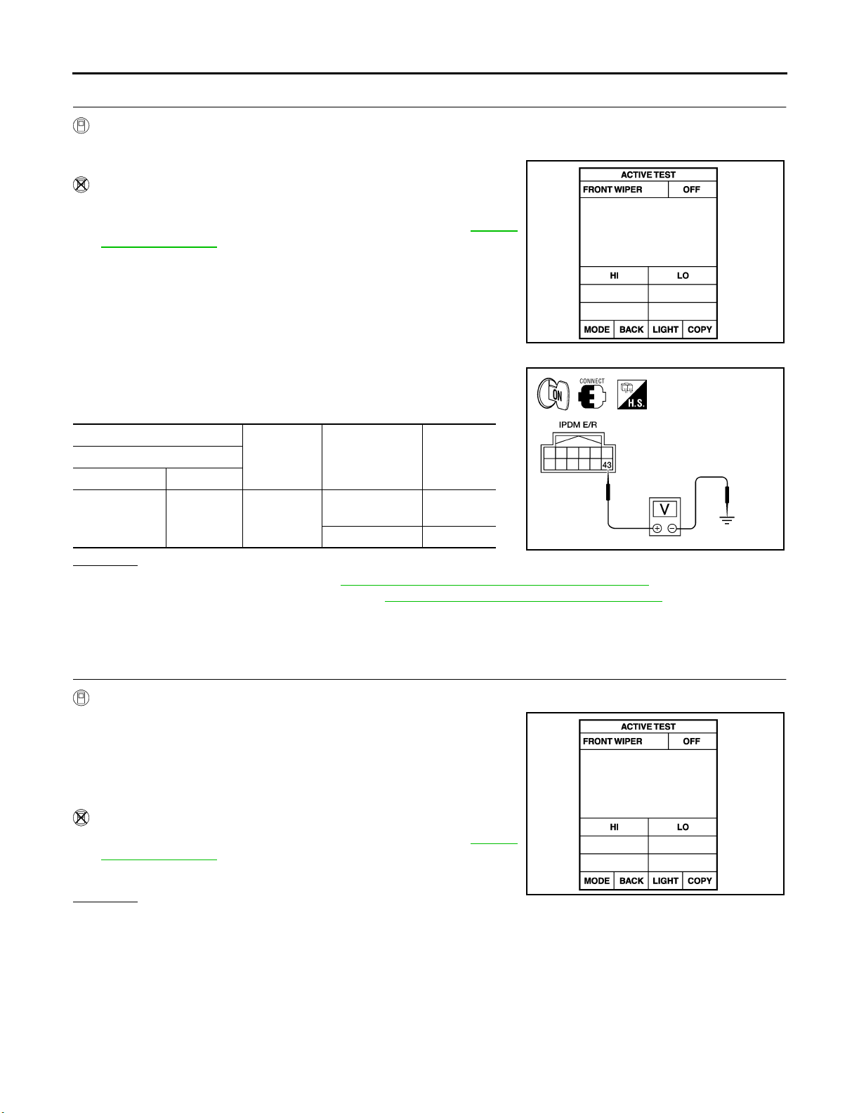
3. IPDM E/R INSPECTION
With CONSULT-II
1. Connect IPDM E/R connector and front wiper motor connector.
2. Select "LO" on "ACTIVE TEST" screen.
Without CONSULT-II
1. Connect IPDM E/R connector and front wiper motor connector.
2. Turn on front wipers using the auto active test. Refer to PG-24,
"Auto Active Test" .
When front wipers are operating and when stopped, measure voltage between IPDM E/R harness connector E122 terminal 43 and
ground.
IPDM E/R
(+)
Connector Terminal
E122 43 Ground
(–) Condition
Wiper operating
Wiper stopped 0V
OK or NG
OK >> Replace IPDM E/R. Refer to PG-33, "Removal and Installation of IPDM E/R" .
NG >> Replace front wiper motor. Refer to WW-27, "
Voltage
(Approx.)
Battery
voltage
WIPER MOTOR AND LINKAGE" .
SKIA 3486E
WKIA1431E
ONLY FRONT WIPER LOW DOES NOT OPERATE
Inspection Procedure
1. CHECK IPDM E/R TO FRONT WIPERS
With CONSULT-II
1. Select "IPDM E/R" with CONSULT-II, and select "ACTIVE
TEST" on "SELECT DIAG MODE" screen.
2. Select "FRONT WIPER" on "SELECT TEST ITEM" screen.
3. Select "LO" on "ACTIVE TEST" screen.
4. Confirm front wiper low operation.
Without CONSULT-II
1. Turn on front wipers using auto active test. Refer to PG-24,
"Auto Active Test" .
2. Confirm front wiper low operation.
OK or NG
OK >> GO TO 4.
NG >> GO TO 2.
SKIA 3486E
Revision: September 2005 2006 Xterra
WW-20
Page 28
FRONT WIPER AND WASHER SYSTEM
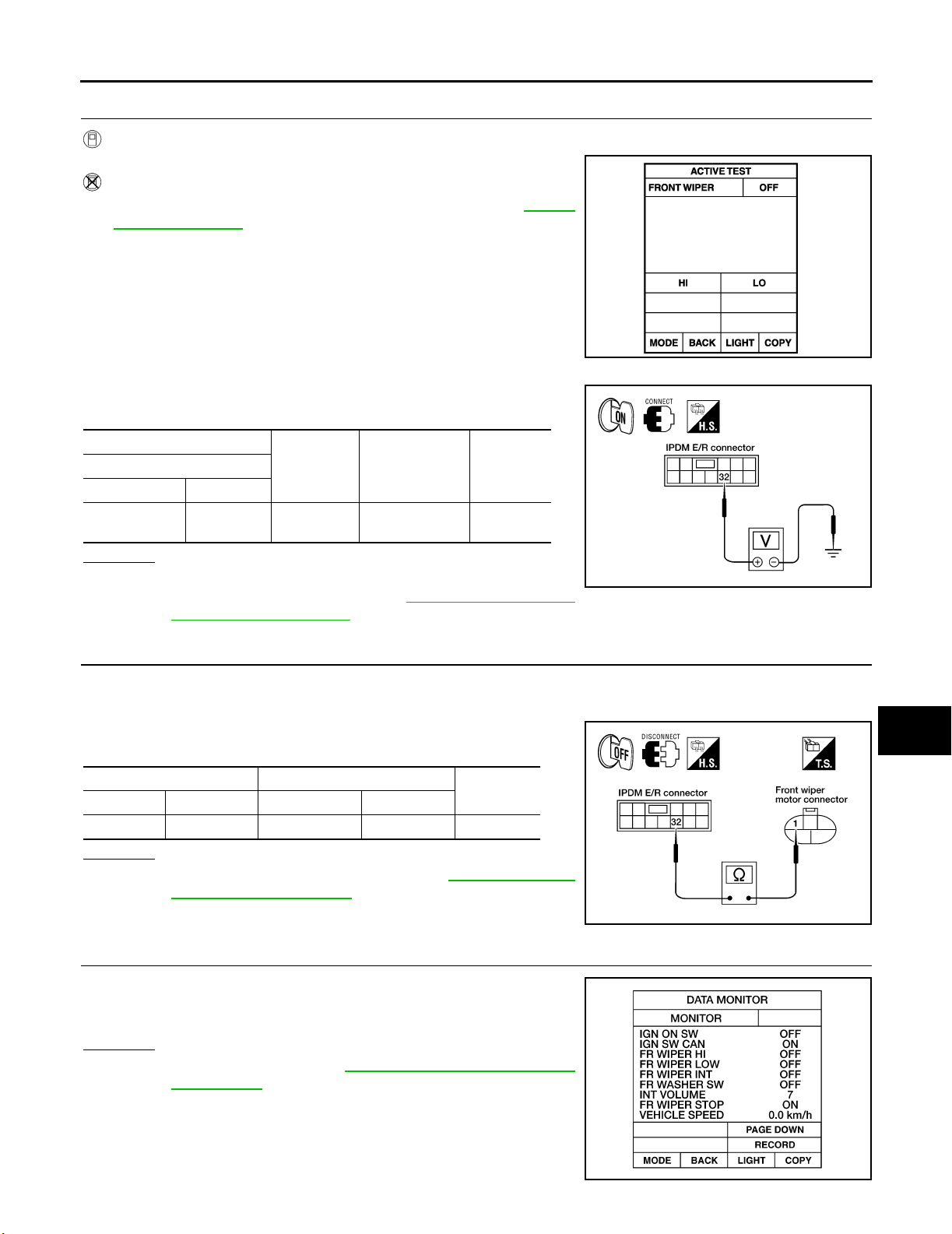
2. IPDM E/R INSPECTION
With CONSULT-II
1. Select "LO" on "ACTIVE TEST" screen.
Without CONSULT-II
1. Turn on front wipers using the auto active test. Refer to PG-24,
"Auto Active Test" .
When front wiper relay is operating, check voltage between IPDM E/
R terminal and ground.
IPDM E/R
(+)
Connector Terminal
E121 32 Ground Wiper operating
(–) Condition
OK or NG
OK >> GO TO 3.
NG >> Replace IPDM E/R. Refer to PG-33, "
Installation of IPDM E/R" .
Volt age
(Approx.)
Battery
voltage
Removal and
SKIA 3486E
WKIA3759E
A
B
C
D
E
F
G
H
I
3. IPDM E/R TO FRONT WIPERS CIRCUIT INSPECTION
1. Turn ignition switch OFF.
2. Disconnect IPDM E/R connector and front wiper motor connector.
3. Check continuity between IPDM E/R harness connector terminal
and front wiper motor harness connector terminal.
IPDM E/R Front wiper motor
Connector Terminal Connector Terminal
E121 32 E23 1 Yes
Continuity
OK or NG
OK >> Replace the wiper motor. Refer to WW-27, "WIPER
MOTOR AND LINKAGE" .
NG >> Repair harness or connector.
4. COMBINATION SWITCH TO BCM INSPECTION
Select "BCM" on CONSULT-II. With "WIPER" data monitor, check
that "FR WIPER LO" turns ON-OFF according to operation of wiper
switch.
OK or NG
OK >> Replace BCM. Refer to BCS-26, "Removal and Installa-
tion of BCM" .
NG >> Replace wiper switch. Refer to .
J
WW
L
M
WKIA3197E
WKIA1018E
Revision: September 2005 2006 Xterra
WW-21
Page 29
FRONT WIPER AND WASHER SYSTEM
ONLY FRONT WIPER HI DOES NOT OPERATE
Inspection Procedure
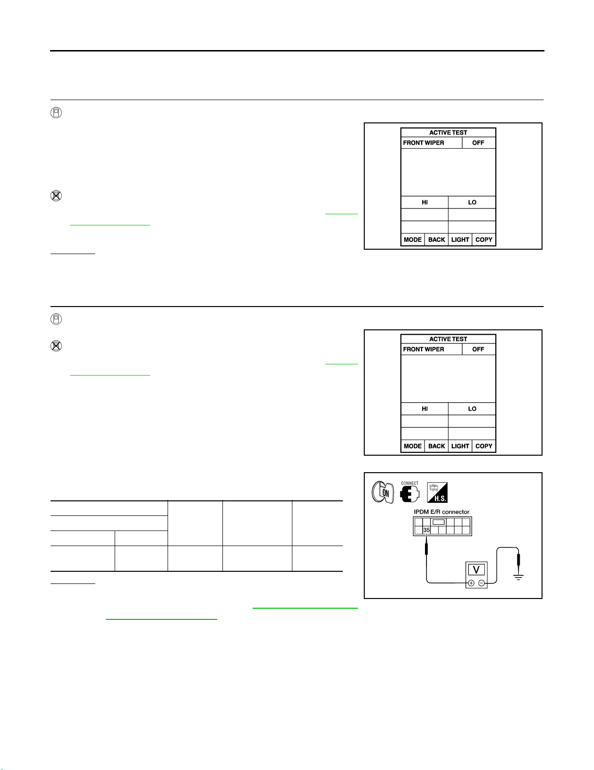
1. CHECK IPDM E/R TO FRONT WIPERS
With CONSULT-II
1. Select "IPDM E/R" with CONSULT-II, and select "ACTIVE
TEST" on "SELECT DIAG MODE" screen.
2. Select "FRONT WIPER" on "SELECT TEST ITEM" screen.
3. Select "HI" on "ACTIVE TEST" screen.
4. Confirm front wiper high operation.
Without CONSULT-II
1. Turn on front wipers using auto active test. Refer to PG-24,
"Auto Active Test" .
2. Confirm front wiper operation.
OK or NG
OK >> GO TO 4.
NG >> GO TO 2.
2. IPDM E/R INSPECTION
SKIA 3486E
With CONSULT-II
1. Select "HI" on "ACTIVE TEST" screen.
Without CONSULT-II
1. Turn on front wipers using the auto active test. Refer to PG-24,
"Auto Active Test" .
When front wiper relay high is operating, check voltage between
IPDM E/R terminal and ground.
IPDM E/R
(+)
Connector Terminal
E121 35 Ground Wiper operating
(–) Condition
Voltage
(Approx.)
Battery
voltage
OK or NG
OK >> GO TO 3.
NG >> Replace IPDM E/R. Refer to PG-33, "
Removal and
Installation of IPDM E/R" .
SKIA 3486E
WKIA3760E
Revision: September 2005 2006 Xterra
WW-22
Page 30
FRONT WIPER AND WASHER SYSTEM
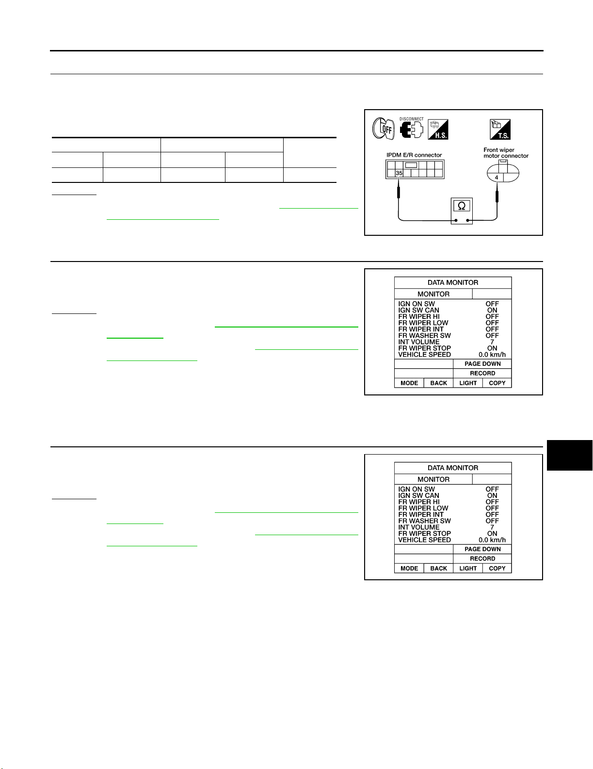
3. IPDM E/R TO FRONT WIPERS CIRCUIT INSPECTION
1. Turn ignition switch OFF.
2. Disconnect IPDM E/R connector and front wiper motor connector.
3. Check continuity between IPDM E/R harness connector terminal
and front wiper motor harness connector terminal.
IPDM E/R Front wiper motor
Connector Terminal Connector Terminal
E121 35 E23 4 Yes
Continuity
OK or NG
OK >> Replace the wiper motor. Refer to WW-27, "WIPER
MOTOR AND LINKAGE" .
NG >> Repair harness or connector.
4. COMBINATION SWITCH TO BCM INSPECTION
Select "BCM" on CONSULT-II. With "WIPER" data monitor, check
that "FR WIPER HI" turns ON-OFF according to operation of wiper
switch.
OK or NG
OK >> Replace BCM. Refer to BCS-26, "Removal and Installa-
tion of BCM" .
NG >> Replace wiper switch. Refer to WW-28, "
WASHER SWITCH" .
WIPER AND
WKIA3199E
A
B
C
D
E
F
G
H
ONLY FRONT WIPER INT DOES NOT OPERATE
Inspection Procedure
1. CHECK COMBINATION SWITCH TO BCM
Select "BCM" on CONSULT-II. With "WIPER" data monitor, check
that "FR WIPER INT" turns ON-OFF according to operation of wiper
switch.
OK or NG
OK >> Replace BCM. Refer to BCS-26, "Removal and Installa-
tion of BCM" .
NG >> Replace wiper switch. Refer to WW-28, "
WASHER SWITCH" .
WIPER AND
I
WKIA1018E
J
WW
L
M
WKIA1018E
Revision: September 2005 2006 Xterra
WW-23
Page 31
FRONT WIPER AND WASHER SYSTEM
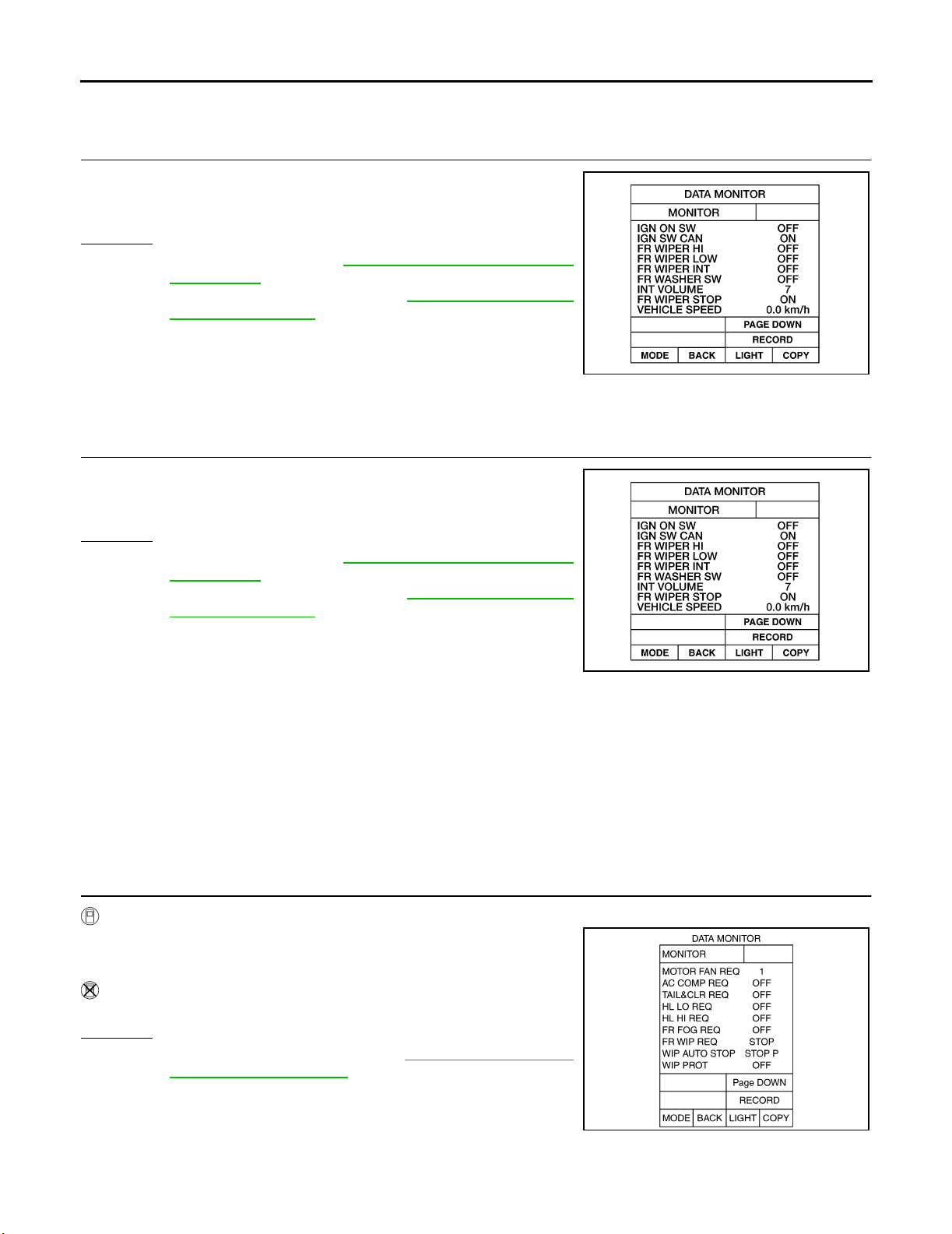
FRONT WIPER INTERMITTENT OPERATION SWITCH POSITION CANNOT BE ADJUSTED
Inspection Procedure
1. CHECK COMBINATION SWITCH TO BCM
Select "BCM" on CONSULT-II. With "WIPER" data monitor, check
that "INT VOLUME" changes in order from 1 to 7 according to operation of the intermittent switch dial position.
OK or NG
OK >> Replace BCM. Refer to BCS-26, "Removal and Installa-
tion of BCM" .
NG >> Replace wiper switch. Refer to WW-28, "
WASHER SWITCH" .
WIPER AND
WKIA1018E
WIPERS DO NOT WIPE WHEN FRONT WASHER OPERATES
Inspection Procedure
1. CHECK COMBINATION SWITCH TO BCM
Select "BCM" on CONSULT-II. With "WIPER" data monitor, check
that "FR WASHER SW" turns ON-OFF according to operation of
front washer switch.
OK or NG
OK >> Replace BCM. Refer to BCS-26, "Removal and Installa-
tion of BCM" .
NG >> Replace wiper switch. Refer to WW-28, "
WASHER SWITCH" .
WIPER AND
WKIA1018E
FRONT WIPERS OPERATE FOR 10 SECONDS, STOP FOR 20 SECONDS, AND AFTER
REPEATING THIS OPERATION FIVE TIMES, THEY BECOME INOPERATIVE
CAUTION:
● When auto stop signal has not varied for 10 seconds or longer while IPDM E/R is operating front
wipers, IPDM E/R considers front wipers locked and stops wiper output, which causes this symptom.
● This status can be checked by using IPDM E/R "DATA MONITOR". Under this condition, "WIP
PROT" reads "BLOCK".
Inspection Procedure
1. CHECK IPDM E/R TO FRONT WIPER MOTOR
With CONSULT-II
Select "IPDM E/R" with CONSULT-II. With data monitor, confirm that
"WIP AUTO STOP" changes from "ACT P" to "STOP P" according to
wiper operation.
Without CONSULT-II
GO TO 2.
OK or NG
OK >> Replace IPDM E/R. Refer to PG-33, "Removal and
Installation of IPDM E/R" .
NG >> GO TO 2.
SKIA 5301E
Revision: September 2005 2006 Xterra
WW-24
Page 32
FRONT WIPER AND WASHER SYSTEM
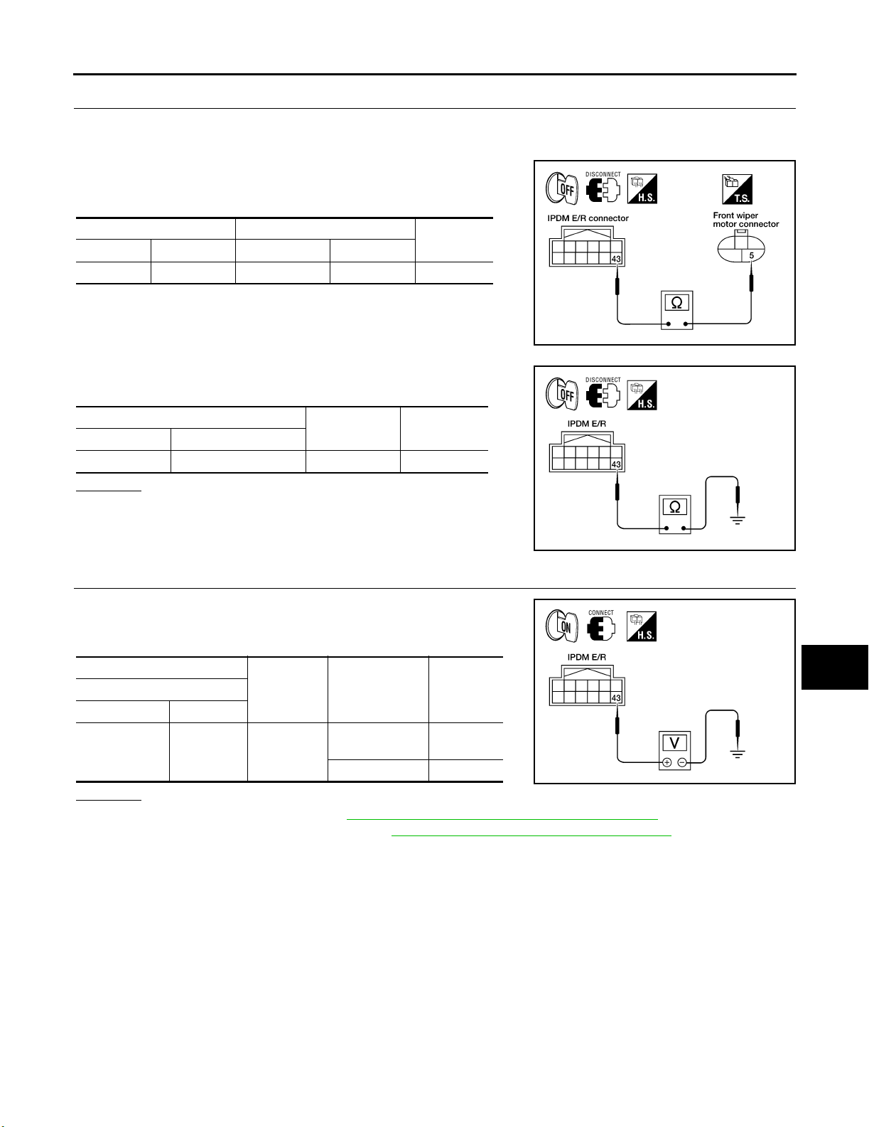
2. IPDM E/R TO FRONT WIPER MOTOR CONTINUITY INSPECTION
1. Turn ignition switch OFF.
2. Disconnect IPDM E/R connector and front wiper motor connector.
3. Check continuity between IPDM E/R harness connector E122
terminal 43 and front wiper motor harness connector E23 terminal 5.
IPDM E/R Front wiper motor
Connector Terminal Connector Terminal
E122 43 E23 5 Yes
Continuity
4. Check continuity between IPDM E/R harness connector E122
terminal 43 and ground.
IPDM E/R
Connector Terminal
E122 43 Ground No
Continuity
OK or NG
OK >> Connect connectors. GO TO 3.
NG >> Repair harness or connector.
3. IPDM E/R TO FRONT WIPER MOTOR GROUND CONTINUITY INSPECTION
WKIA3195E
WKIA1429E
A
B
C
D
E
F
G
H
I
While front wiper motor is stopped and while operating, measure
voltage between IPDM E/R harness connector E122 terminal 43 and
ground.
IPDM E/R
(+)
Connector Terminal
E122 43 Ground
(–) Condition
Wiper operating
Wiper stopped 0V
Volt age
(Approx.)
Battery
voltage
OK or NG
OK >> Replace IPDM E/R. Refer to PG-33, "Removal and Installation of IPDM E/R" .
NG >> Replace front wiper motor. Refer to WW-27, "
WIPER MOTOR AND LINKAGE" .
WKIA1431E
J
WW
L
M
Revision: September 2005 2006 Xterra
WW-25
Page 33
FRONT WIPER AND WASHER SYSTEM
Removal and Installation EKS00DET
FRONT WIPER ARMS
Removal
1. Remove wiper arm covers and wiper arm nuts.
2. Remove front RH wiper arm and front LH wiper arm.
3. Remove front RH blade assembly and front LH blade assembly.
Installation
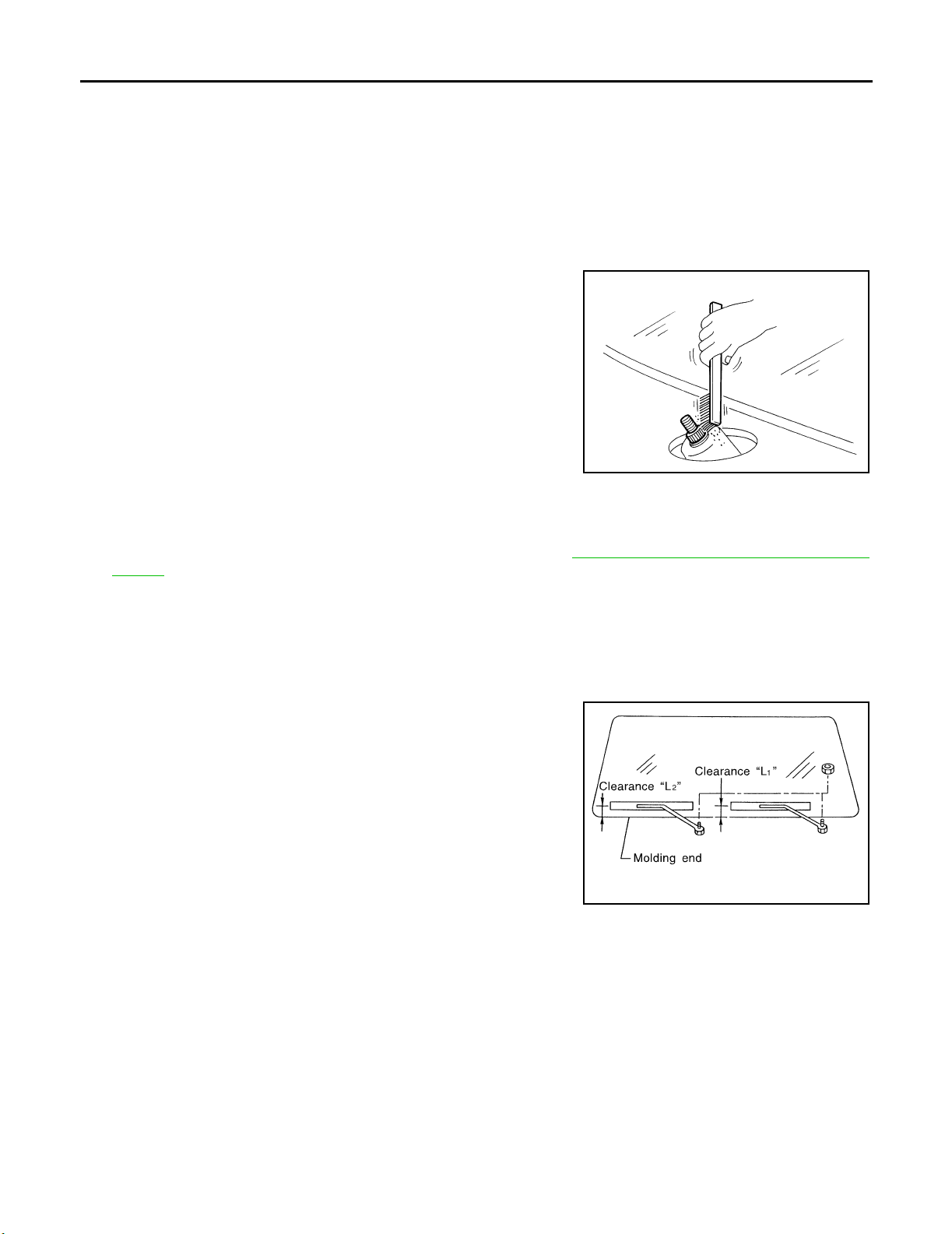
1. Operate wiper motor one full cycle, then turn "OFF" (Auto Stop).
2. Clean up the pivot area as shown. This will reduce possibility of
wiper arm looseness.
SEL02 4J
3. Install front RH blade assembly and front LH blade assembly.
4. Install front RH wiper arm and front LH wiper arm.
5. Ensure that wiper blades stop within proper clearance. Refer to WW-26, "
MENT" .
6. Tighten wiper arm nuts to specified torque, and install wiper arm covers.
Front wiper arm nuts : 23.6 N·m (2.4 kg-m, 17 ft-lb)
FRONT WIPER ARM ADJUST-
FRONT WIPER ARM ADJUSTMENT
1. Operate windshield washer and wiper motor one full cycle, then turn "OFF" (Auto Stop).
2. Lift the wiper blade up and then rest it onto glass surface, check
the blade clearance "L1" and "L2".
Clearance "L1" : 24.5 - 39.5 mm (0.965 - 1.555 in)
Clearance "L2" : 23.5 - 38.5 mm (0.925 - 1.516 in)
3. Remove wiper arm covers and wiper arm nuts.
4. Adjust front wiper arms on wiper motor pivot shafts to obtain
above specified blade clearances.
5. Tighten wiper arm nuts to specified torque, and install wiper arm
covers.
Front wiper arm nuts : 23.6 N·m (2.4 kg-m, 17 ft-lb)
SEL54 3TA
Revision: September 2005 2006 Xterra
WW-26
Page 34
FRONT WIPER AND WASHER SYSTEM
WIPER MOTOR AND LINKAGE
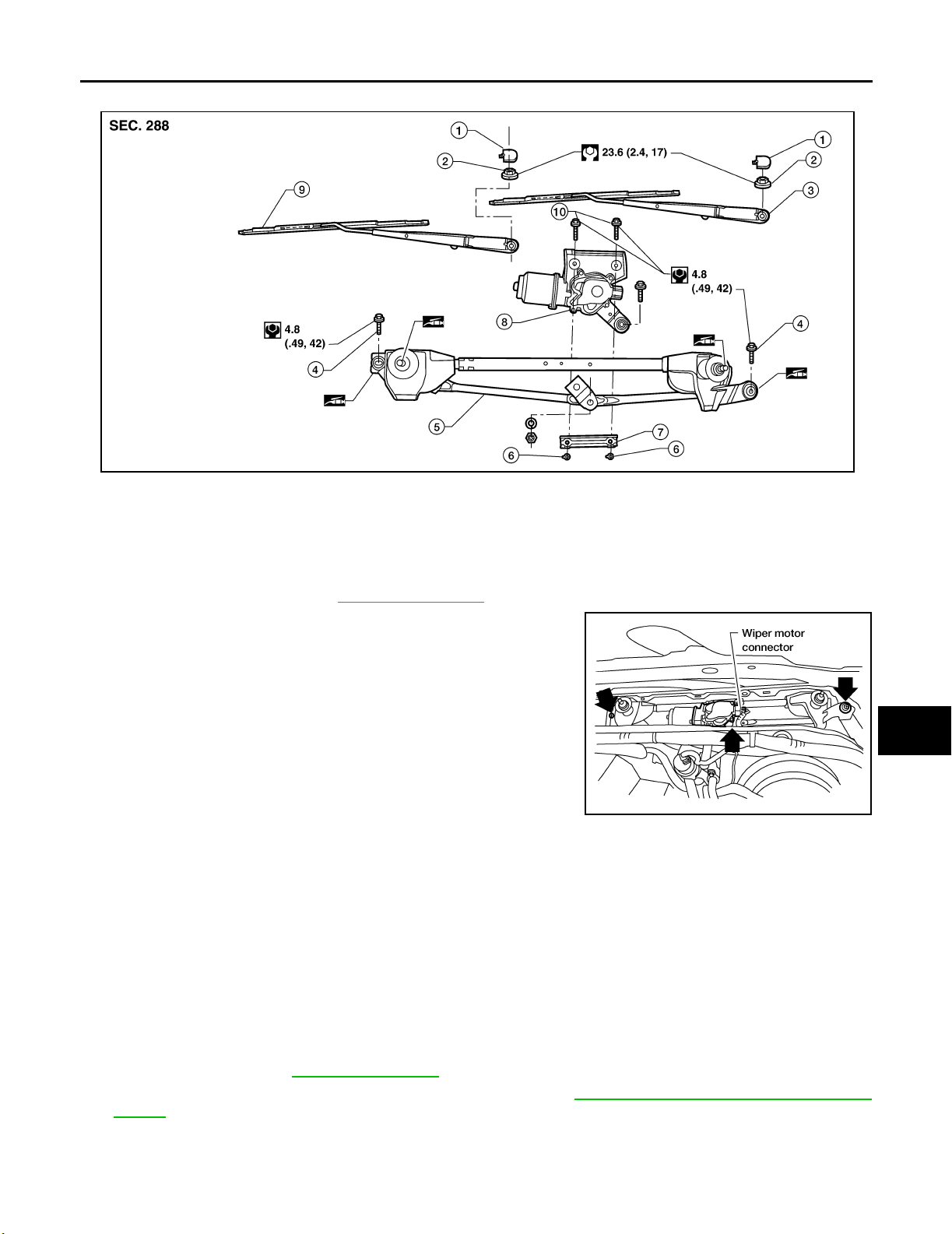
1. Wiper arm covers 2. Wiper arm nuts 3. Front LH wiper arm and blade assembly
4. Wiper frame bolts 5. Wiper frame assembly 6. Wiper motor to frame nuts
7. Wiper motor spacer 8. Wiper motor 9. Front RH wiper arm and blade assembly
10. Wiper motor to frame bolts
A
B
C
D
E
F
WKIA4870E
G
H
Removal
1. Remove the cowl top. Refer to EI-17, "COWL TOP" .
2. Remove wiper frame bolts, disconnect wiper motor connector
and remove wiper frame assembly.
LKIA05 34E
3. Remove wiper motor from wiper frame assembly.
Installation
CAUTION:
● Do not drop the wiper motor or cause it to contact other parts.
● Check the grease conditions of the motor arm and wiper link joint(s). Apply grease if necessary.
1. Connect wiper motor to connector. Turn the wiper switch ON to operate wiper motor, then turn the wiper
switch OFF (auto stop).
2. Disconnect wiper motor connector.
3. Install wiper motor to wiper frame assembly, and install wiper frame assembly.
4. Connect wiper motor electrical connector.
5. Install cowl top. Refer to EI-17, "
6. Ensure that wiper blades stop within proper clearance. Refer to WW-26, "
MENT" .
COWL TOP" .
FRONT WIPER ARM ADJUST-
I
J
WW
L
M
Revision: September 2005 2006 Xterra
WW-27
Page 35
FRONT WIPER AND WASHER SYSTEM
WASHER NOZZLES
Removal
1. Remove the cowl top. Refer to EI-17, "COWL TOP" .
2. Remove washer nozzles.
Installation
Installation is in the reverse order of removal.
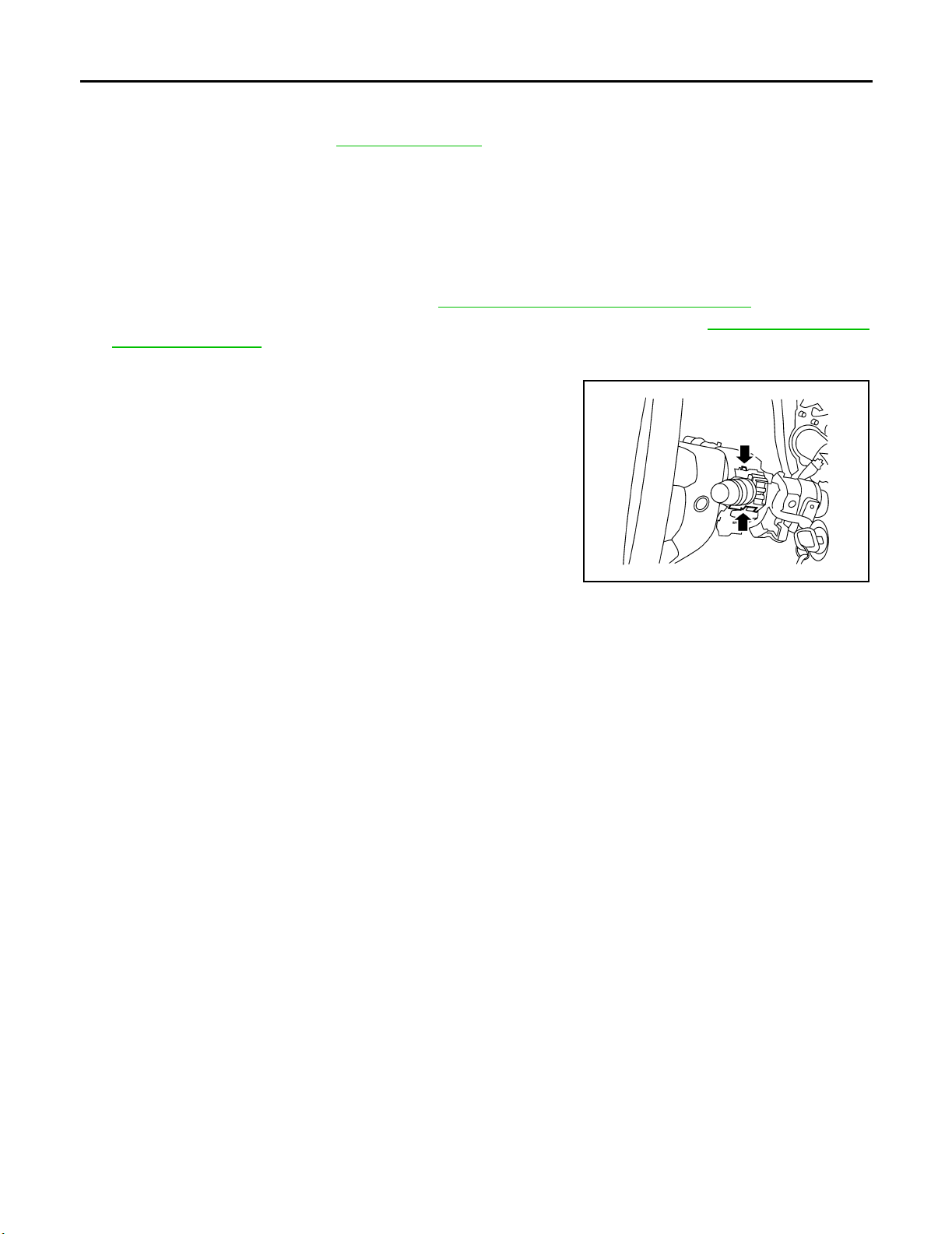
WIPER AND WASHER SWITCH
Removal
1. Remove instrument lower cover LH. Refer to IP-12, "LOWER INSTRUMENT PANEL LH" .
2. Remove steering column cover lower and steering column cover upper. Refer to IP-10, "
PANEL ASSEMBLY " .
3. Disconnect wiper washer switch connector.
4. Pinch tabs at wiper and washer switch base and slide switch
away from steering column.
INSTRUMENT
Installation
Installation is in the reverse order of removal.
WKIA0071E
Revision: September 2005 2006 Xterra
WW-28
Page 36
FRONT WIPER AND WASHER SYSTEM
WASHER FLUID RESERVOIR
Removal
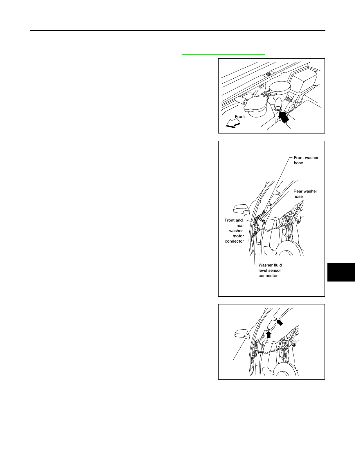
1. Remove passenger front fender protector. Refer to. EI-19, "Front Fender Protector" .
2. Remove clip, then remove washer fluid reservoir filler neck from
washer fluid reservoir.
A
B
C
D
3. Disconnect front and rear washer hoses.
4. Disconnect front and rear washer motor connector.
5. Disconnect washer fluid level sensor connector.
LKIA05 38E
LKIA05 37E
E
F
G
H
I
J
WW
L
6. Remove washer fluid reservoir screws and remove washer fluid
reservoir.
LKIA05 39E
Installation
Installation is in the reverse order of removal.
CAUTION:
After installation, add water up to the upper level of the washer fluid reservoir inlet and check for water
leaks.
Revision: September 2005 2006 Xterra
WW-29
M
Page 37
FRONT WIPER AND WASHER SYSTEM
FRONT AND REAR WASHER MOTOR
Removal
1. Remove washer fluid reservoir. Refer to WW-29, "WASHER FLUID RESERVOIR" .
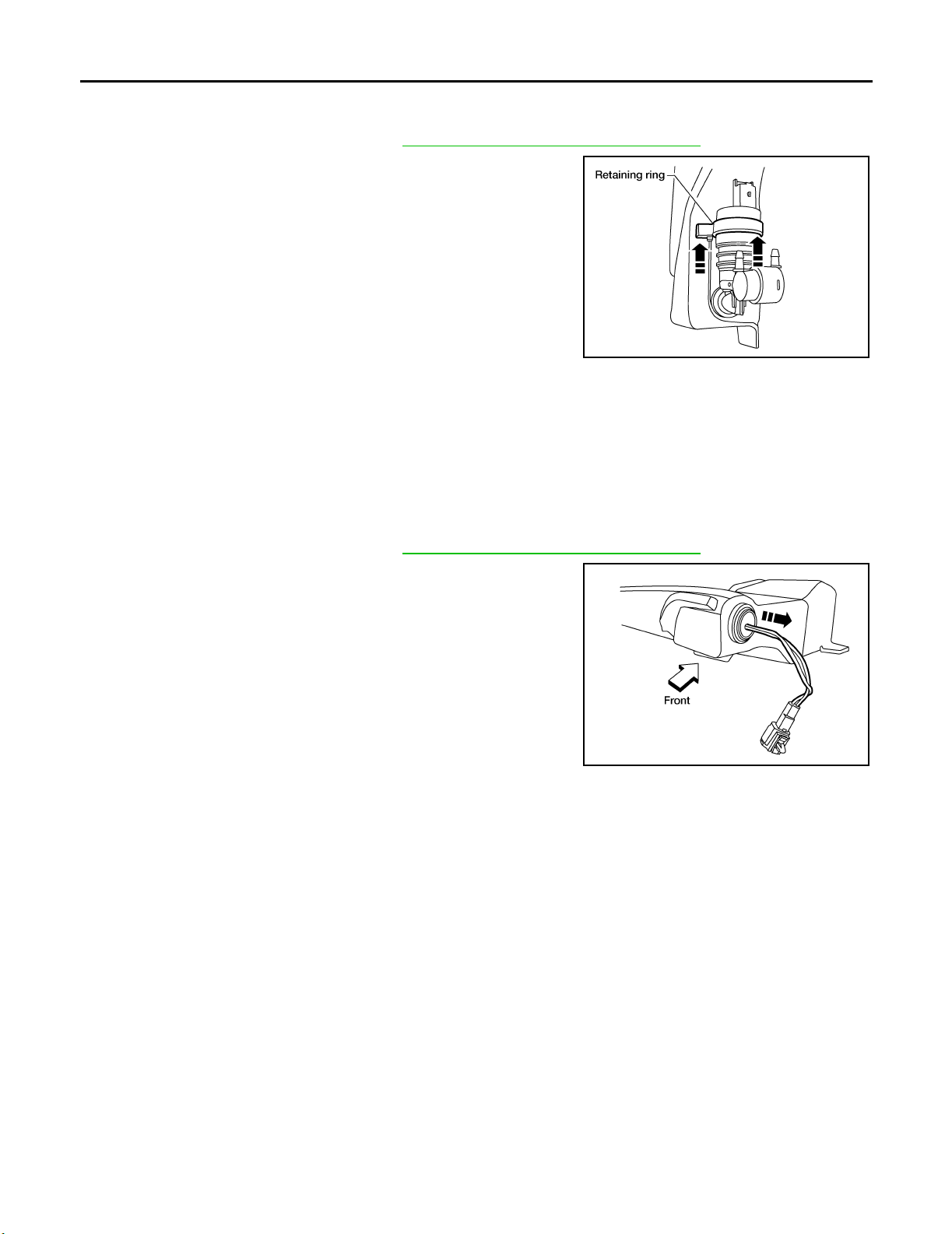
2. Slide retaining ring upward to release front and rear washer
motor.
3. Remove front and rear washer motor from washer fluid reservoir.
Installation
Installation is in the reverse order of removal.
CAUTION:
When installing front and rear washer motor, there should be no packing twists, etc.
LKIA05 40E
WASHER FLUID LEVEL SENSOR
Removal
1. Remove washer fluid reservoir. Refer to WW-29, "WASHER FLUID RESERVOIR" .
2. Lift level sensor out of washer fluid reservoir in the direction of
the arrow as shown.
Installation
Installation is in the reverse order of removal.
LKIA05 41E
Revision: September 2005 2006 Xterra
WW-30
Page 38
FRONT WIPER AND WASHER SYSTEM
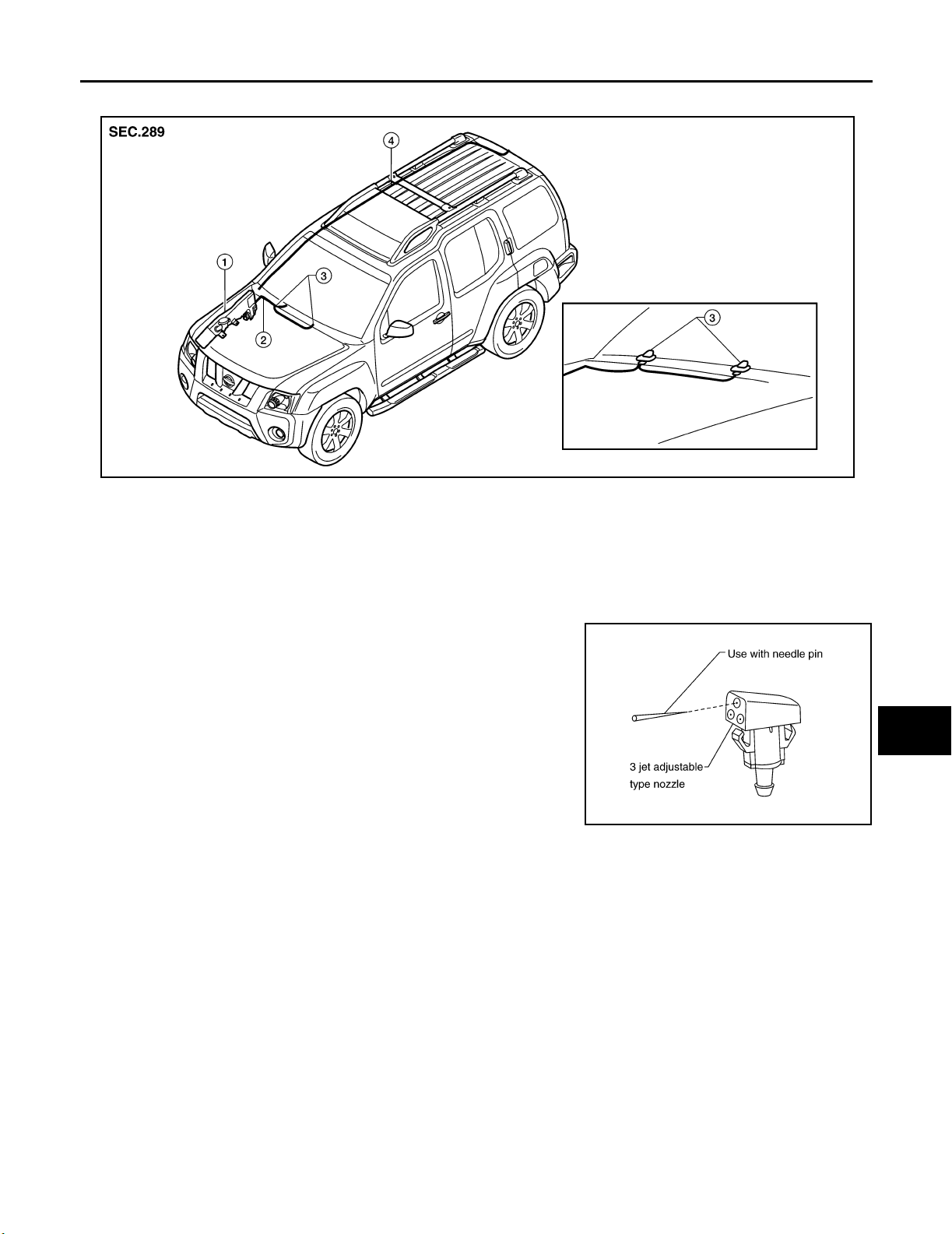
Washer Hose Layout EKS00DEW
WKIA4964E
1. Washer fluid reservoir 2. Front washer hose 3. Washer nozzle
4. Rear washer hose
A
B
C
D
E
F
G
Washer Nozzle Adjustment EKS00HMJ
NOTE:
This vehicle is equipped with adjustable washer nozzles.
1. If not satisfied with washer fluid spray coverage, confirm that the washer nozzle is installed correctly.
2. If the washer nozzle is installed correctly, and the washer fluid
spray coverage is not satisfactory, re-aim washer nozzle.
WKIA3711E
H
I
J
WW
L
M
Revision: September 2005 2006 Xterra
WW-31
Page 39
REAR WIPER AND WASHER SYSTEM
REAR WIPER AND WASHER SYSTEM PFP:28710
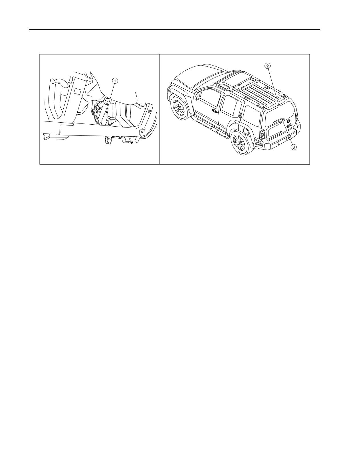
Components Parts and Harness Connector Location EKS00DF1
WKIA5037E
1. BCM
M18, M19, M20
(view with lower instrument panel LH removed)
2. Rear washer nozzle 3. Rear wiper motor
D509
System Description EKS00DF2
● The wiper switch (combination switch) is composed of a combination of 5 output terminals and 5 input ter-
minals. Terminal combination status is read by the BCM (body control module) when switch is turned ON.
● The BCM controls rear wiper ON and INT (intermittent) operation.
Power is supplied at all times
● through 50A fusible link (letter g , located in fuse and fusible link box)
● to BCM terminal 70.
With the ignition switch in ON or START position, power is supplied
● through 10A fuse [No. 15, located in the fuse block (J/B)]
● to combination switch terminal 2, and
● through 10A fuse [No. 1, located in the fuse block (J/B)]
● to BCM terminal 38.
Ground is supplied
● to BCM terminal 67 and
● to combination switch terminal 9
● through grounds M57, M61 and M79.
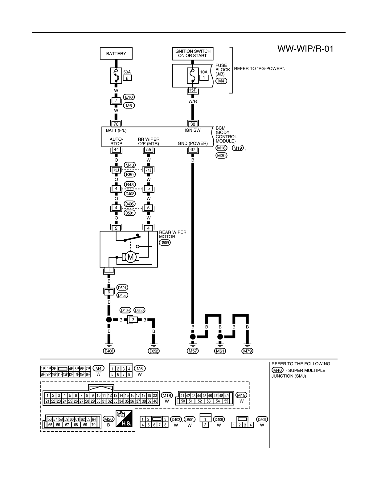
REAR WIPER OPERATION
When the ignition switch is in the ON or START position, and the rear wiper switch is in the ON position, the
BCM detects a rear wiper ON request through the combination switch (wiper switch) reading function.
The BCM will control the rear wiper motor as follows.
Power is supplied
● through BCM terminal 55
● to rear wiper motor terminal 4.
Ground is supplied
● to rear wiper motor terminal 1
● through grounds D406 and D652.
With power and ground supplied, the rear wiper motor operates.
INTERMITTENT OPERATION
The rear wiper motor operates the wiper arm at low speed approximately every 7 seconds.
Revision: September 2005 2006 Xterra
WW-32
Page 40

REAR WIPER AND WASHER SYSTEM
When the wiper switch is in the rear wiper INT position, the BCM detects a rear wiper INT request through the
combination switch (wiper switch) reading function.
When BCM operates rear wiper motor, power is supplied
● through BCM terminal 55
● to rear wiper motor terminal 4.
Ground is supplied
● to rear wiper motor terminal 1
● through grounds D406 and D652.
With power and ground supplied, the rear wiper operates in intermittent mode.
A
B
C
AUTO STOP OPERATION
When the rear wiper arm is not located at the base of the rear window, and the rear wiper switch is turned
OFF, the rear wiper motor will continue to operate until the rear wiper arm is at the base of the rear window.
When the rear wiper arm reaches the base, rear wiper motor terminals 2 and 1 are connected.
Ground is supplied
● to BCM terminal 44
● through rear wiper motor terminal 2
● through rear wiper motor terminal 1
● through grounds D406 and D652.
REAR WASHER OPERATION
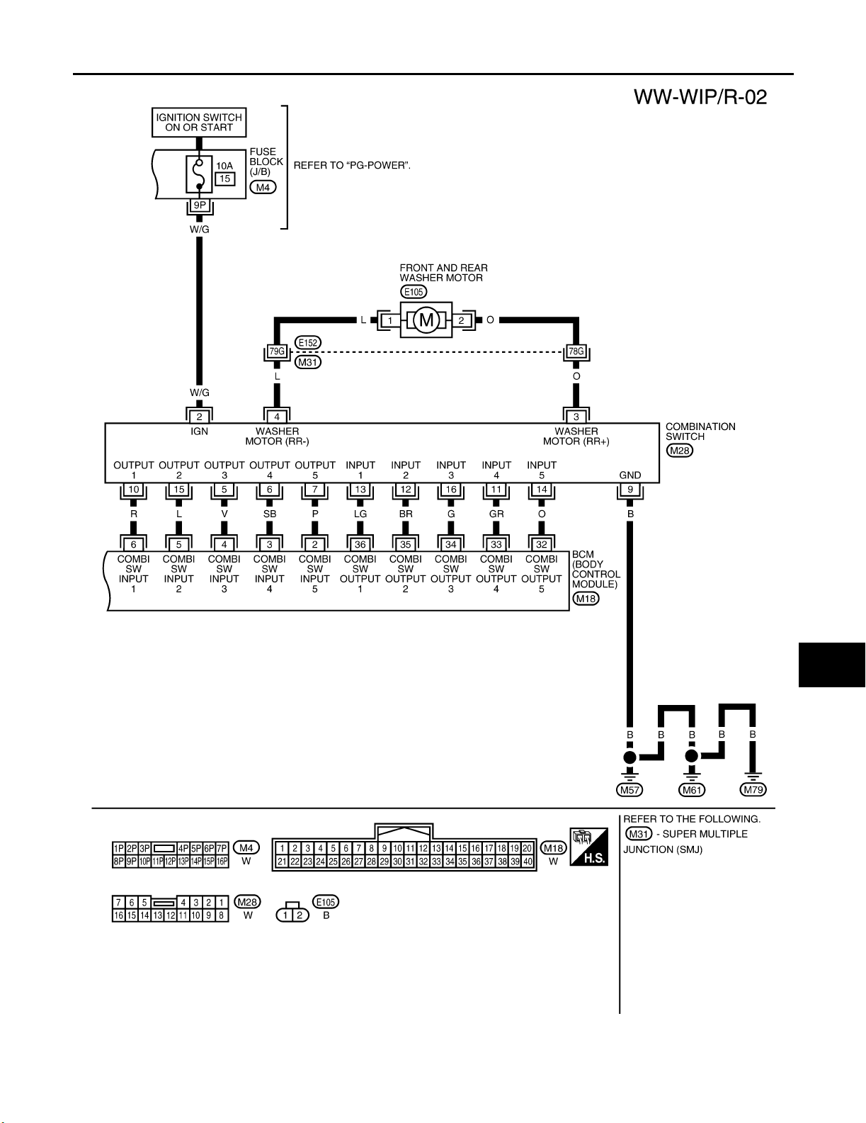
When the ignition switch is in the ON or START position, and the front and rear washer switches are OFF, the
front and rear washer motor is supplied power
● through 10A fuse [No. 15, located in the fuse block (J/B)]
● through combination switch (wiper switch) terminal 2
● through combination switch (wiper switch) terminal 3
● to front and rear washer motor terminal 2.
When the rear wiper switch is in rear washer position, the BCM detects a rear washer signal by BCM wiper
switch reading function. Combination switch ground is supplied
● to front and rear washer motor terminal 1
● through combination switch (wiper switch) terminal 4
● through combination switch (wiper switch) terminal 9
● through grounds M57, M61 and M79.
With ground supplied, the front and rear washer motor is operated in the rear direction.
When the BCM detects that the rear washer motor has operated for 0.4 seconds or longer, BCM operates the
rear wiper motor.
When the BCM detects that the rear washer switch is in OFF, the rear wiper motor cycles approximately 3
times and then stops.
If the rear washer is operated with the rear wiper switch in the INT position, normal rear wiper operation will
take over. Once the rear washer switch is released the rear wiper will return to INT operation.
D
E
F
G
H
I
J
WW
L
M
BCM WIPER SWITCH READING FUNCTION
Refer to BCS-3, "COMBINATION SWITCH READING FUNCTION" .
Revision: September 2005 2006 Xterra
WW-33
Page 41
REAR WIPER AND WASHER SYSTEM
Wiring Diagram — WIP/R — EKS00DF3
WKWA4337E
Revision: September 2005 2006 Xterra
WW-34
Page 42
REAR WIPER AND WASHER SYSTEM
A
B
C
D
E
F
G
H
I
J
WW
L
M
WKWA4338E
Revision: September 2005 2006 Xterra
WW-35
Page 43
REAR WIPER AND WASHER SYSTEM
Terminals a nd Ref er ence Values for B CM EKS00DF4
Refer to BCS-12, "Ter min al s an d Re fe re nce Va lu es fo r BC M" .
How to Proceed With Trouble Diagnosis EKS00DF5
1. Confirm the symptoms and customer complaint.
2. Understand operation description and function description. Refer to WW-32, "
3. Perform the Preliminary Check. Refer to WW-36, "
Preliminary Check" .
System Description" .
4. Check symptom and repair or replace the cause of malfunction.
5. Does the rear wiper operate normally? If YES: GO TO 6. If NO: GO TO 4.
6. Inspection End.
Preliminary Check EKS00DF6
INSPECTION FOR POWER SUPPLY AND GROUND CIRCUIT
Refer to BCS-16, "BCM Power Supply and Ground Circuit Check" .
CONSULT-II Function (BCM) EKS00DF7
CONSULT-II can display each diagnostic item using the diagnostic test modes shown following.
BCM diagnostic
test item
Inspection by part
Diagnostic mode Description
Supports inspections and adjustments. Commands are transmitted to the BCM
WORK SUPPORT
DATA MONITOR Displays BCM input/output data in real time.
ACTIVE TEST Operation of electrical loads can be checked by sending drive signal to them.
SELF-DIAG RESULTS Displays BCM self-diagnosis results.
CAN DIAG SUPPORT MNTR The result of transmit/receive diagnosis of CAN communication can be read.
ECU PART NUMBER BCM part number can be read.
CONFIGURATION Performs BCM configuration read/write functions.
for setting the status suitable for required operation, input/output signals are
received from the BCM and received data is displayed.
CONSULT-II OPERATION
CAUTION:
If CONSULT-II is used with no connection of CONSULT-II CONVERTER, malfunctions might be
detected in self-diagnosis depending on control unit which carries out CAN communication.
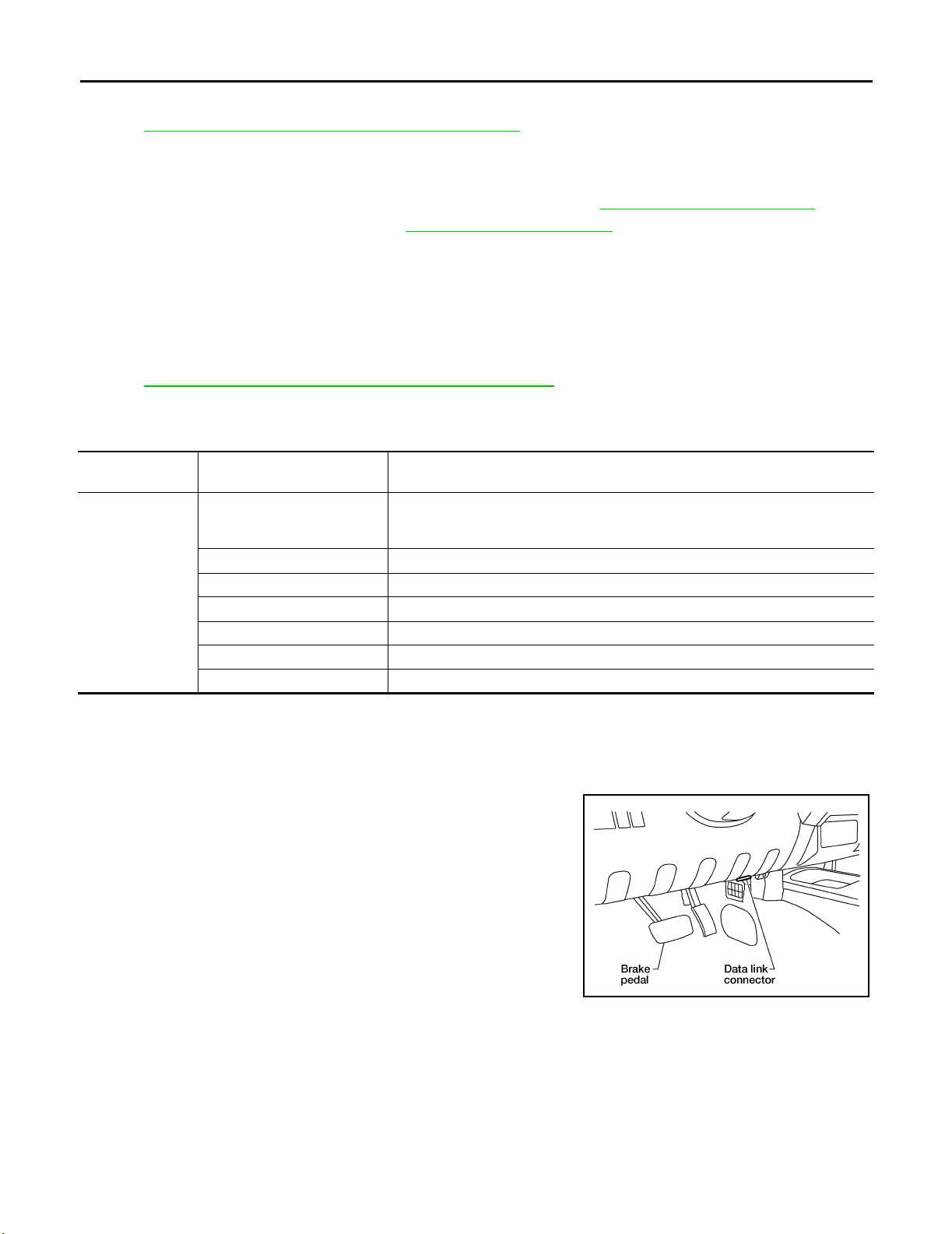
1. With the ignition switch OFF, connect CONSULT-II and CONSULT-II CONVERTER to the data link connector, then turn the
ignition switch ON.
BBIA 0538E
Revision: September 2005 2006 Xterra
WW-36
Page 44
REAR WIPER AND WASHER SYSTEM
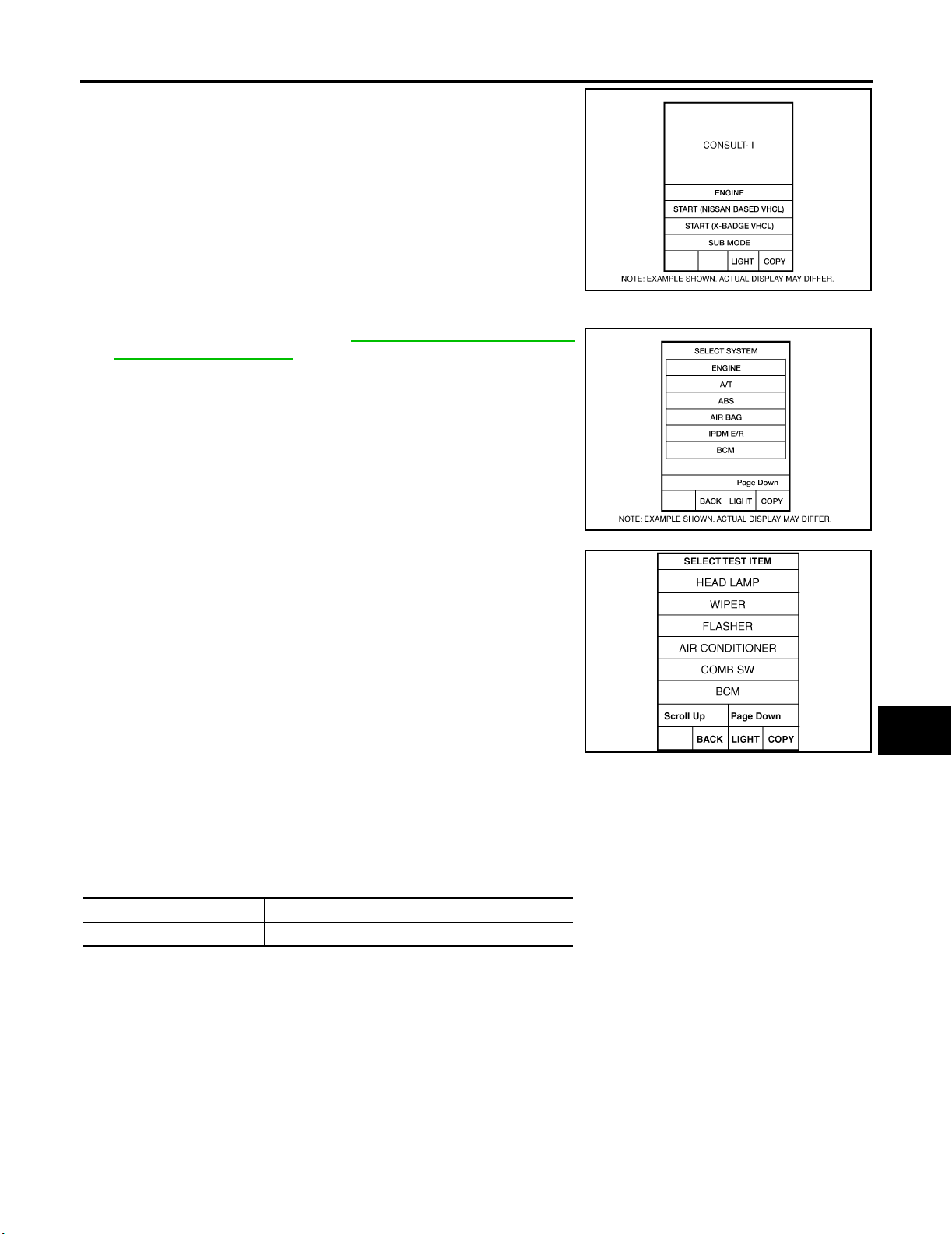
2. Touch "START (NISSAN BASED VHCL)".
3. Touch "BCM" on the "SELECT SYSTEM" screen.
If "BCM" is not indicated, go to GI-41, "
Connector (DLC) Circuit" .
CONSULT-II Data Link
A
B
C
BCIA0 029E
D
E
F
G
BCIA0 030E
4. Select the desired part to be diagnosed on the "SELECT TEST
ITEM" screen.
LKIA01 83E
DATA MONITOR
Operation Procedure
1. Touch "WIPER" on "SELECT TEST ITEM" screen.
2. Touch "DATA MONITOR" on "SELECT DIAG MODE" screen.
3. Touch either "ALL SIGNALS" or "SELECTION FROM MENU" on "SELECT MONITOR ITEM" screen.
ALL SIGNALS Monitors all the items.
SELECTION FROM MENU Selects and monitors the individual item selected.
4. Touch "START".
5. When "SELECTION FROM MENU" is selected, touch items to be monitored. When "ALL SIGNALS" is
selected, all the items will be monitored.
6. Touch "RECORD" while monitoring, then the status of the monitored item can be recorded. To stop
recording, touch "STOP".
H
I
J
WW
L
M
Revision: September 2005 2006 Xterra
WW-37
Page 45
REAR WIPER AND WASHER SYSTEM
Display Item List
Monitor item name
"OPERATION OR UNIT"
IGN ON SW "ON/OFF" Displays "IGN Position (ON)/OFF, ACC Position (OFF)" status as judged from ignition switch signal.
IGN SW CAN "ON/OFF"
FR WIPER INT "ON/OFF" Displays "Front Wiper INT (ON)/Other (OFF)" status as judged from wiper switch signal.
FR WIPER LOW "ON/OFF" Displays "Front Wiper LOW (ON)/Other (OFF)" status as judged from wiper switch signal.
FR WIPER HI "ON/OFF" Displays "Front Wiper HI (ON)/Other (OFF)" status as judged from wiper switch signal.
FR WASHER SW "ON/OFF" Displays "Front Washer Switch (ON)/Other (OFF)" status as judged from wiper switch signal.
INT VOLUME (1 - 7) Displays interm ittent operation dial position setting (1 - 7) as judged from wiper switch signal.
VEHICLE SPEED "0.0 km/h" Displays vehicle speed as received over CAN communication.
FR WIPER STOP "ON/OFF" Displays "Stopped (ON)/Operating (OFF)" status as judged from the auto-stop signal.
RR WIPER INT "ON/OFF" Displays "Rear Wiper INT (ON)/Other (OFF)" status as judged from wiper switch signal.
RR WIPER ON "ON/OFF" Displays "Rear Wiper (ON)/Other (OFF)" status as judged from wiper switch signal.
RR WASHER SW "ON/OFF" Displays "Rear Washer Switch (ON)/Other (OFF)" status as judged from wiper switch signal.
RR WIPER STOP "ON/OFF" Displays "Stopped (OFF)/Operating (ON)" status as judged from the auto stop switch 1.
RR AUTO STP 2 "ON/OFF" Displays "Stopped (OFF)/Operating (ON)" status as judged from the auto stop switch 2.
Displays "IGN Position (ON)/OFF, ACC Position (OFF)" status as judged from CAN communications.
Contents
ACTIVE TEST
Operation Procedure
1. Touch "WIPER" on the "SELECT TEST ITEM" screen.
2. Touch "ACTIVE TEST" on the "SELECT DIAG MODE" screen.
3. Touch item to be tested and check operation of the selected item.
4. During the operation check, touching "BACK" deactivates the operation.
Display Item List
Te s t i t e m D i s pl a y o n C O N S U LT- I I s cr e e n D e s c ri p t i on
Front wiper HI output FR WIPER (HI) Front wiper HI can be operated by any ON-OFF operation.
Front wiper LO output FR WIPER (LO) Front wiper LO can be operated by any ON-OFF operation.
Front wiper INT output FR WIPER (INT) Front wiper INT can be operated by any ON-OFF operation.
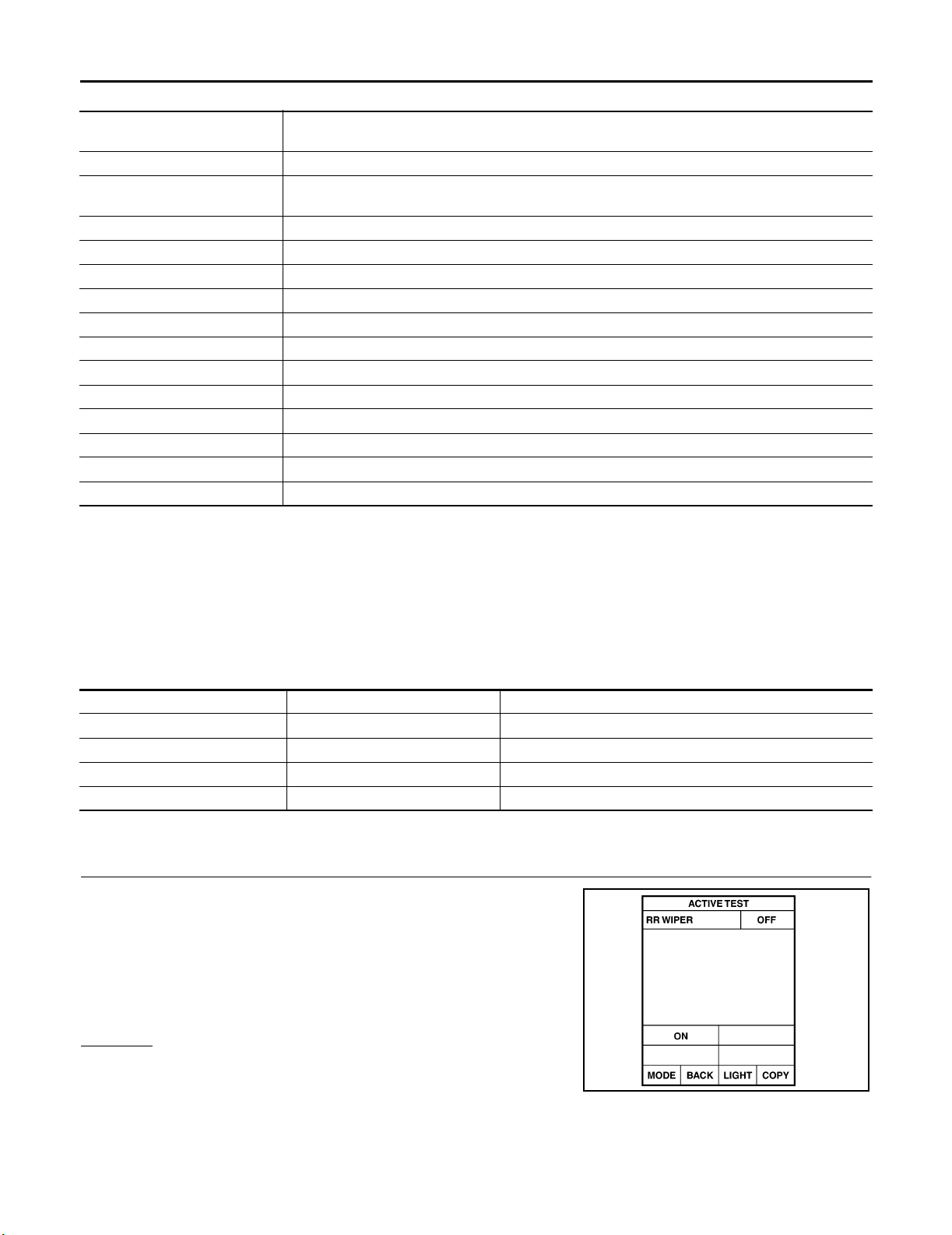
Rear wiper output RR WIPER Rear wiper can be operated by any ON-OFF operation.
Rear Wiper Does Not Operate EKS00DF8
1. REAR WIPER ACTIVE TEST
1. Select "BCM" on CONSULT-II, and select "WIPER" on "SELECT
TEST ITEM" screen.
2. Select "ACTIVE TEST" on "SELECT DIAG MODE" screen.
3. Select "RR WIPER" on "SELECT TEST ITEM" screen.
4. Make sure rear wiper operates.
Wiper should operate.
OK or NG
OK >> GO TO 6.
NG >> GO TO 2.
Revision: September 2005 2006 Xterra
WW-38
SKIA 3503E
Page 46
REAR WIPER AND WASHER SYSTEM
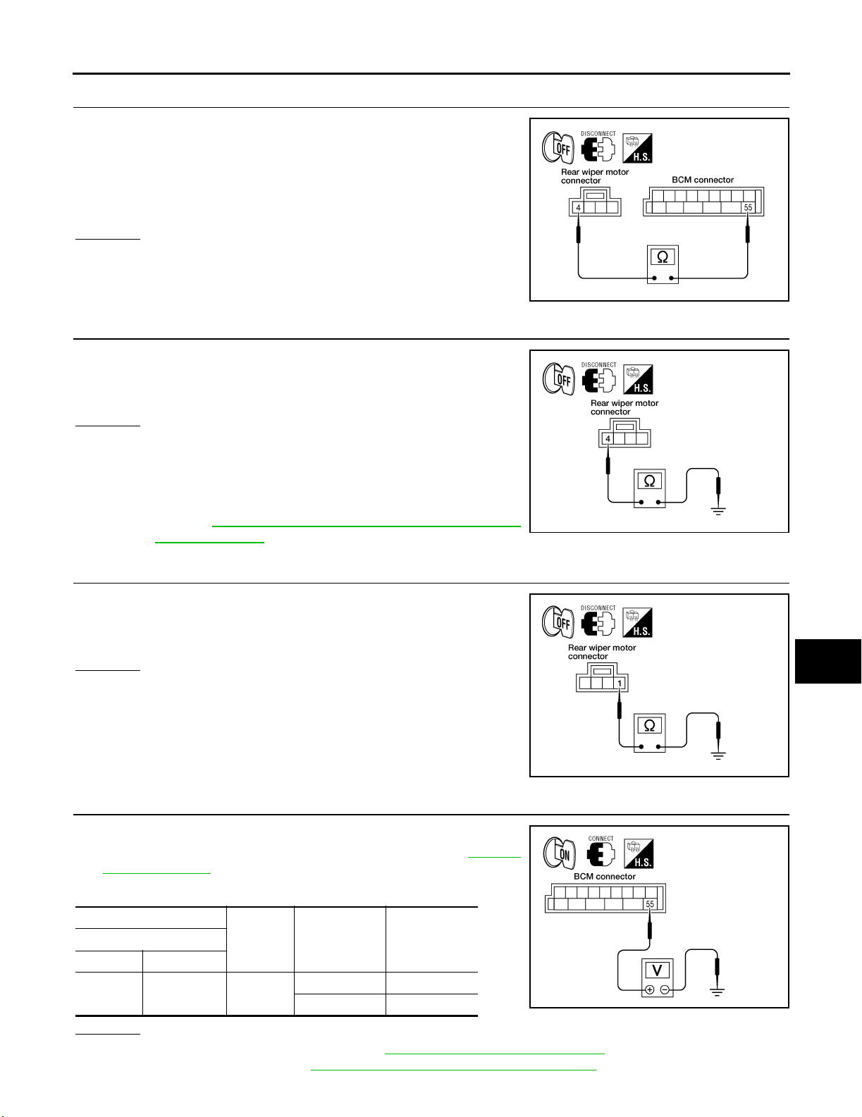
2. CHECK REAR WIPER MOTOR CIRCUIT
1. Turn ignition switch OFF.
2. Disconnect BCM connector and rear wiper motor connector.
3. Check continuity between BCM harness connector M19 terminal
55 and rear wiper motor harness connector D509 terminal 4.
55 - 4 : Continuity should exist.
OK or NO
OK >> GO TO 3.
NO >> Repair harness or connector.
3. CHECK REAR WIPER MOTOR SHORT CIRCUIT
Check continuity between rear wiper motor harness connector D509
terminal 4 and ground.
4 - Ground : Continuity should not exist.
OK or NG
OK >> GO TO 4.
NG >> After repairing harness, be sure to disconnect battery
negative cable, and then reconnect it. After the battery
cable is reconnected, the steering angle sensor neutral
position must be reset on vehicles equipped with VDC.
Refer to BRC-57, "
Adjustment of Steering Angle Sensor
Neutral Position" .
4. CHECK GROUND CIRCUIT
A
B
C
D
LKIA05 48E
E
F
G
H
LKIA05 49E
I
Check continuity between rear wiper motor harness connector D509
terminal 1 and ground.
1 - Ground : Continuity should exist.
OK or NG
OK >> GO TO 5.
NG >> Repair harness or connector.
5. CHECK REAR WIPER OPERATING
1. Connect BCM connector and rear wiper motor connector.
2. Select "RR WIPER" during "ACTIVE TEST". Refer to WW-38,
"ACTIVE TEST" . When rear wiper is operating, check voltage
between BCM harness connector terminal and ground.
BCM
(+)
Connector Terminal
M19 55 Ground
(–) Condition
Stop ped 0V
ON operation Battery voltage
OK or NG
OK >> Replace rear wiper motor. Refer to WW-44, "REAR WIPER MOTOR" .
NG >> Replace BCM. Refer to BCS-26, "
Voltage
(Approx.)
Removal and Installation of BCM" .
LKIA05 50E
LKIA05 51E
J
WW
L
M
Revision: September 2005 2006 Xterra
WW-39
Page 47
REAR WIPER AND WASHER SYSTEM
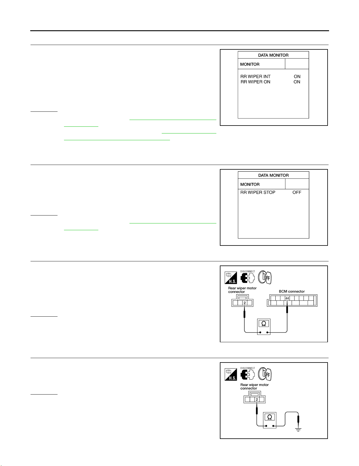
6. CHECK COMBINATION SWITCH INPUT SIGNAL
Select "BCM" on CONSULT-II. With "WIPER" data monitor, make
sure "RR WIPER INT", "RR WIPER ON" turn ON-OFF according to
operation of wiper switch.
When wiper switch is in
INT position
When wiper switch is in
ON position
OK or NG
OK >> Replace BCM. Refer to BCS-26, "Removal and Installa-
tion of BCM" .
NG >> Check the wiper switch. Refer to WW-7, "
TION SWITCH READING FUNCTION" .
: RR WIPER INT ON
: RR WIPER ON ON
SKIA 4243E
COMBINA-
Rear Wiper Stop Position Is Incorrect EKS00DF9
1. CHECK COMBINATION SWITCH INPUT SIGNAL
Select "BCM" on CONSULT-II. With "WIPER" data monitor, make
sure "RR WIPER STOP" turns ON-OFF according to wiper operation.
When wiper switch is in
OFF position
: RR WIPER STOP OFF
OK or NG
OK >> Replace BCM. Refer to BCS-26, "Removal and Installa-
tion of BCM" .
NG >> GO TO 2.
2. CHECK REAR WIPER MOTOR CIRCUIT
1. Turn ignition switch OFF.
2. Disconnect BCM connector and rear wiper motor connector.
3. Check continuity between BCM harness connector M19 terminal
44 and rear wiper motor harness connector D509 terminal 2.
44 - 2 : Continuity should exist.
OK or NG
OK >> GO TO 3.
NG >> Repair harness or connector.
3. CHECK REAR WIPER MOTOR SHORT CIRCUIT
Check continuity between rear wiper motor harness connector D509
terminal 2 and ground.
2 - Ground : Continuity should not exist.
SKIA 4244E
LKIA05 52E
OK or NG
OK >> GO TO 4.
NG >> Repair harness or connector.
LKIA05 53E
Revision: September 2005 2006 Xterra
WW-40
Page 48
REAR WIPER AND WASHER SYSTEM
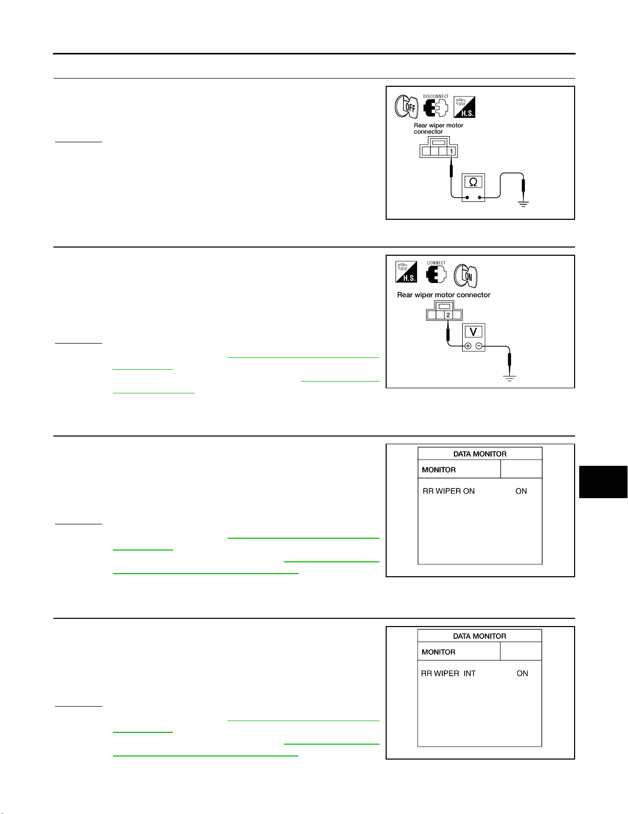
4. CHECK GROUND CIRCUIT
Check continuity between rear wiper motor harness connector D509
terminal 1 and ground.
1 - Ground : Continuity should exist.
OK or NG
OK >> GO TO 5.
NG >> Repair harness or connector.
LKIA05 50E
5. CHECK AUTO STOP SIGNAL
1. Connect BCM connector.
2. Turn ignition switch ON.
3. Check voltage between rear wiper motor harness connector
D509 terminal 2 and ground.
2 - Ground : Battery voltage should exist.
OK or NG
OK >> Replace BCM. Refer to BCS-26, "Removal and Installa-
tion of BCM" .
NG >> Replace rear wiper motor. Refer to WW-44, "
WIPER MOTOR" .
REAR
LKIA05 54E
Only Rear Wiper Does Not Operate EKS00DFA
1. CHECK COMBINATION SWITCH INPUT SIGNAL
Select "BCM" on CONSULT-II. With "WIPER" data monitor, make
sure "RR WIPER ON" turns ON-OFF according to operation of wiper
switch.
When rear wiper switch is in
ON position
: RR WIPER ON ON
A
B
C
D
E
F
G
H
I
J
WW
OK or NG
OK >> Replace BCM. Refer to BCS-26, "Removal and Installa-
tion of BCM" .
NG >> Check the wiper switch. Refer to WW-7, "
TION SWITCH READING FUNCTION" .
COMBINA-
SKIA 4248E
Only Rear Wiper Intermittent Does Not Operate EKS00DFB
1. CHECK COMBINATION SWITCH INPUT SIGNAL
Select "BCM" on CONSULT-II. With "WIPER" data monitor, make
sure "RR WIPER INT" turns ON-OFF according to operation of wiper
switch.
When rear wiper switch is in
INT position
OK or NG
OK >> Replace BCM. Refer to BCS-26, "Removal and Installa-
tion of BCM" .
NG >> Check the wiper switch. Refer to WW-7, "
TION SWITCH READING FUNCTION" .
Revision: September 2005 2006 Xterra
: RR WIPER INT ON
COMBINA-
SKIA 4249E
WW-41
L
M
Page 49
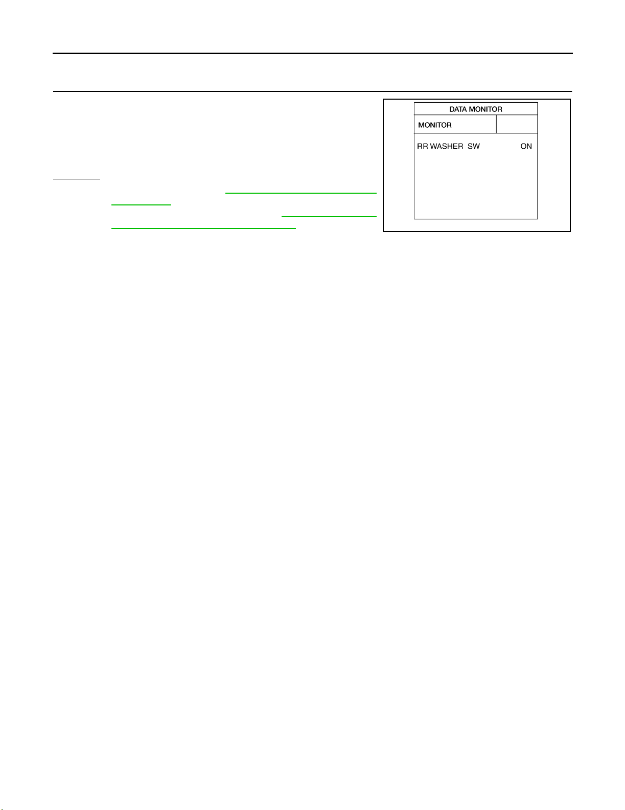
REAR WIPER AND WASHER SYSTEM
Wiper Does Not Wipe When Rear Washer Operates EKS00DFC
1. CHECK COMBINATION SWITCH INPUT SIGNAL
Select "BCM" on CONSULT-II. With "WIPER" data monitor, make
sure "RR WASHER SW" turns ON-OFF according to operation of
rear washer switch.
When rear wiper switch is in
WASHER position
OK or NG
OK >> Replace BCM. Refer to BCS-26, "Removal and Installa-
tion of BCM" .
NG >> Check the wiper switch. Refer to WW-7, "
TION SWITCH READING FUNCTION" .
: RR WASHER SW ON
COMBINA-
SKIA 4250E
Revision: September 2005 2006 Xterra
WW-42
Page 50
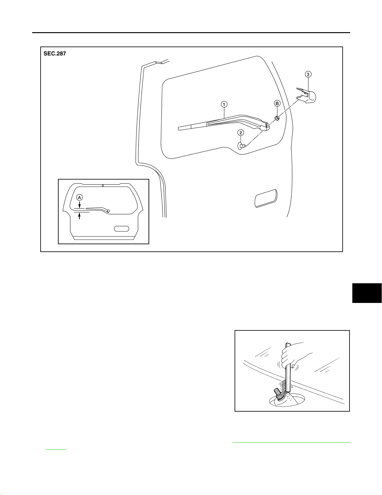
REAR WIPER AND WASHER SYSTEM
Removal and Installation EKS0 0HM K
A
B
C
D
E
F
G
1. Rear wiper arm and blade 2. Rear wiper motor pivot seal 3. Rear wiper arm cover
A. Wiper arm parallel to back glass edge B. Rear wiper arm nut
REAR WIPER ARM
Removal
1. Remove rear wiper arm cover, and remove rear wiper arm nut.
2. Remove rear wiper arm.
3. Remove wiper blade.
Installation
1. Clean up the pivot area as illustrated. This will reduce the possibility of wiper arm looseness.
WKIA4965E
H
I
J
WW
L
M
SEL02 4J
2. Install rear wiper blade.
3. Install rear wiper arm.
4. Ensure that rear wiper blade stops at proper position. Refer to WW-43, "
REAR WIPER ARM ADJUST-
MENT" .
REAR WIPER ARM ADJUSTMENT
1. Operate rear wiper motor one full cycle, then turn "OFF" (Auto Stop).
Revision: September 2005 2006 Xterra
WW-43
Page 51
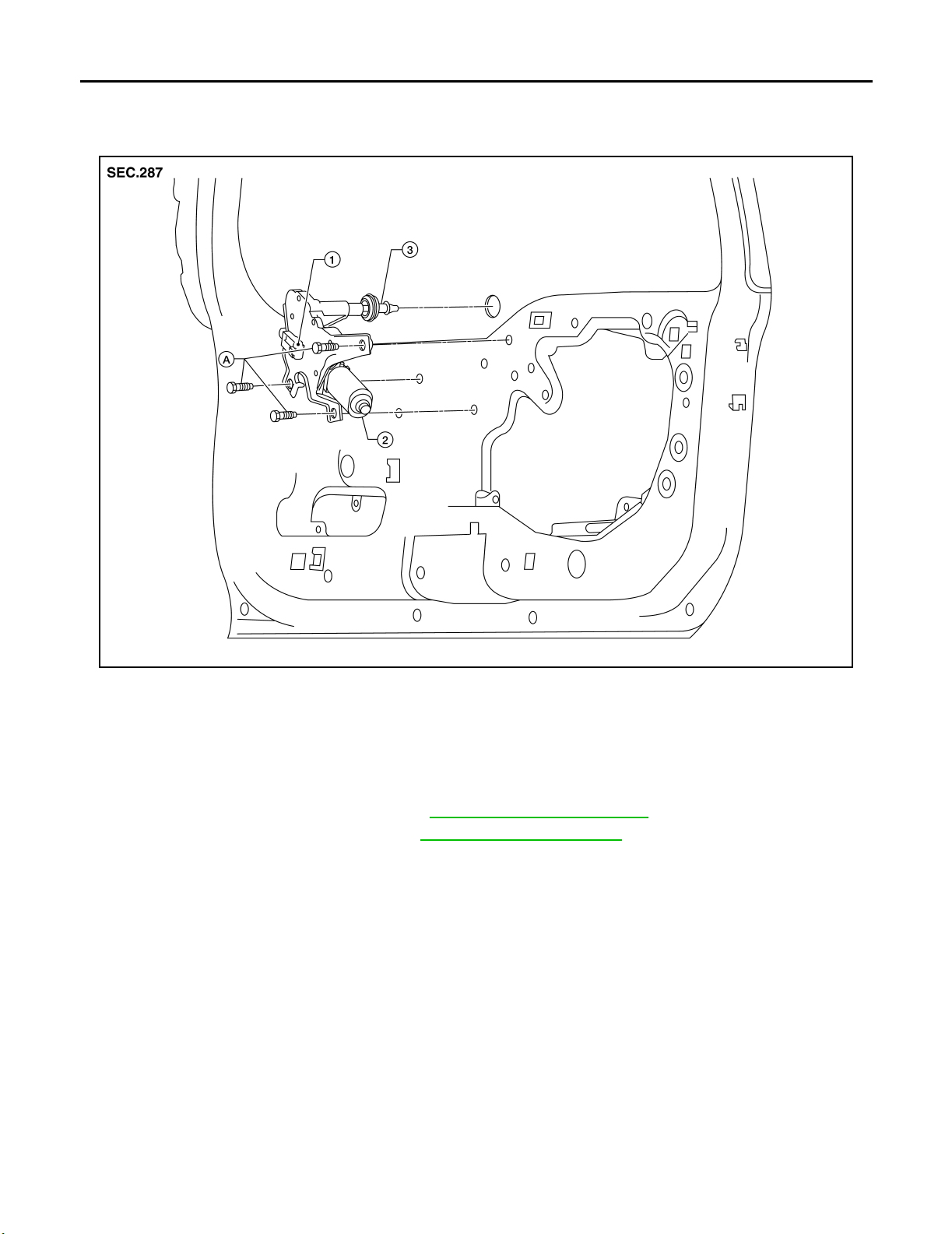
REAR WIPER AND WASHER SYSTEM
2. Adjust rear wiper arm so that wiper arm and blade is parallel with lower edge of back glass, as shown.
3. Install rear wiper arm nut and rear wiper arm cover.
REAR WIPER MOTOR
1. Rear wiper motor harness connector 2. Rear wiper motor 3. Rear motor pivot seal
A. Rear wiper motor bolts
Removal
CAUTION:
● Do not drop rear wiper motor or cause it to contact other parts.
1. Remove rear wiper arm and blade. Refer to WW-43, "
2. Remove back door lower finisher. Refer to EI-35, "
REAR WIPER ARM" .
BACK DOOR TRIM" .
3. Remove rear wiper motor cover.
4. Disconnect rear wiper motor harness connector.
5. Remove rear wiper motor.
6. Remove rear motor pivot seal.
Installation
WKIA4966E
Revision: September 2005 2006 Xterra
WW-44
Page 52
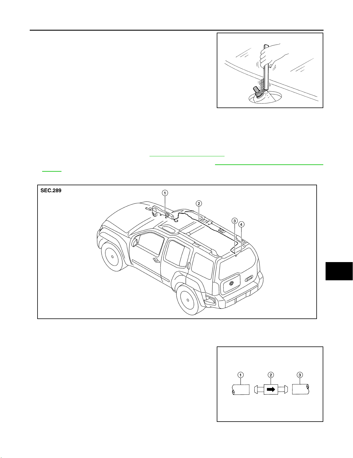
REAR WIPER AND WASHER SYSTEM
1. Clean up the pivot area as illustrated. This will reduce possibility
of wiper arm looseness.
SEL02 4J
2. Install rear motor pivot seal.
3. Install rear wiper motor.
4. Connect rear wiper motor harness connector.
5. Install rear wiper motor cover.
6. Install back door lower finisher. Refer to EI-35, "
7. Ensure that rear wiper blade stops at proper position. Refer to WW-43, "REAR WIPER ARM ADJUST-
MENT" .
BACK DOOR TRIM" .
A
B
C
D
E
F
REAR WASHER HOSE LAYOUT
1. Washer fluid reservoir 2. Rear washer hose 3. Check valve
4. Rear washer nozzle
NOTE:
Connect the check valve (2) to the washer fluid reservoir tube (1) so
that the directional arrow on the check valve (2) points towards the
washer nozzle tube (3).
WKIA4969E
G
H
I
J
WW
L
M
WKIA4242E
Revision: September 2005 2006 Xterra
WW-45
Page 53
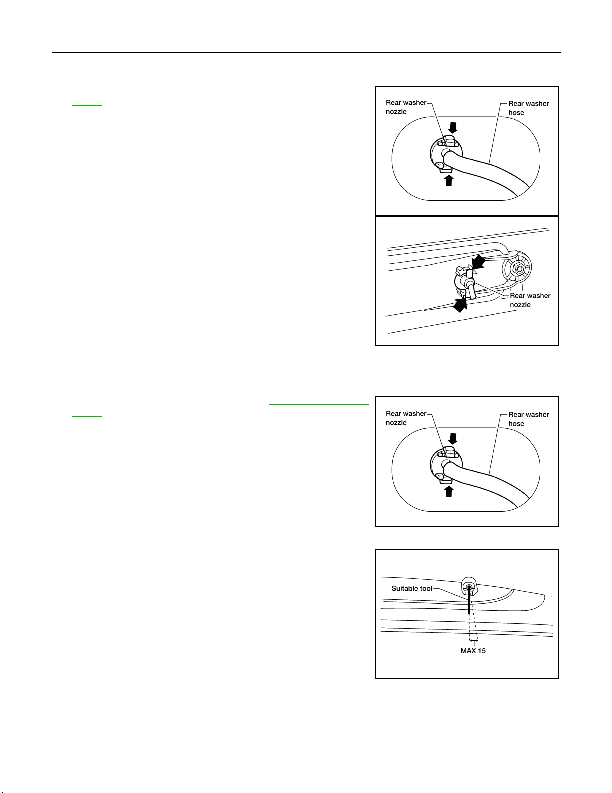
REAR WIPER AND WASHER SYSTEM
REAR WASHER NOZZLE
Removal
1. Remove back door upper finisher. Refer to EI-35, "BACK DOOR
TRIM" .
2. Disconnect rear washer hose from rear washer nozzle.
3. Release retaining clips, and remove rear washer nozzle.
Installation
1. Install rear washer nozzle.
2. Connect rear washer hose.
3. Install back door upper finisher. Refer to EI-35, "
TRIM" .
BACK DOOR
WKIA4035E
LKIA04 18E
WKIA4035E
REAR WASHER NOZZLE ADJUSTMENT
● Adjust washer nozzle with suitable tool as shown.
Adjustable range : ±15° (In any direction)
LKIA03 49E
Revision: September 2005 2006 Xterra
WW-46
Page 54
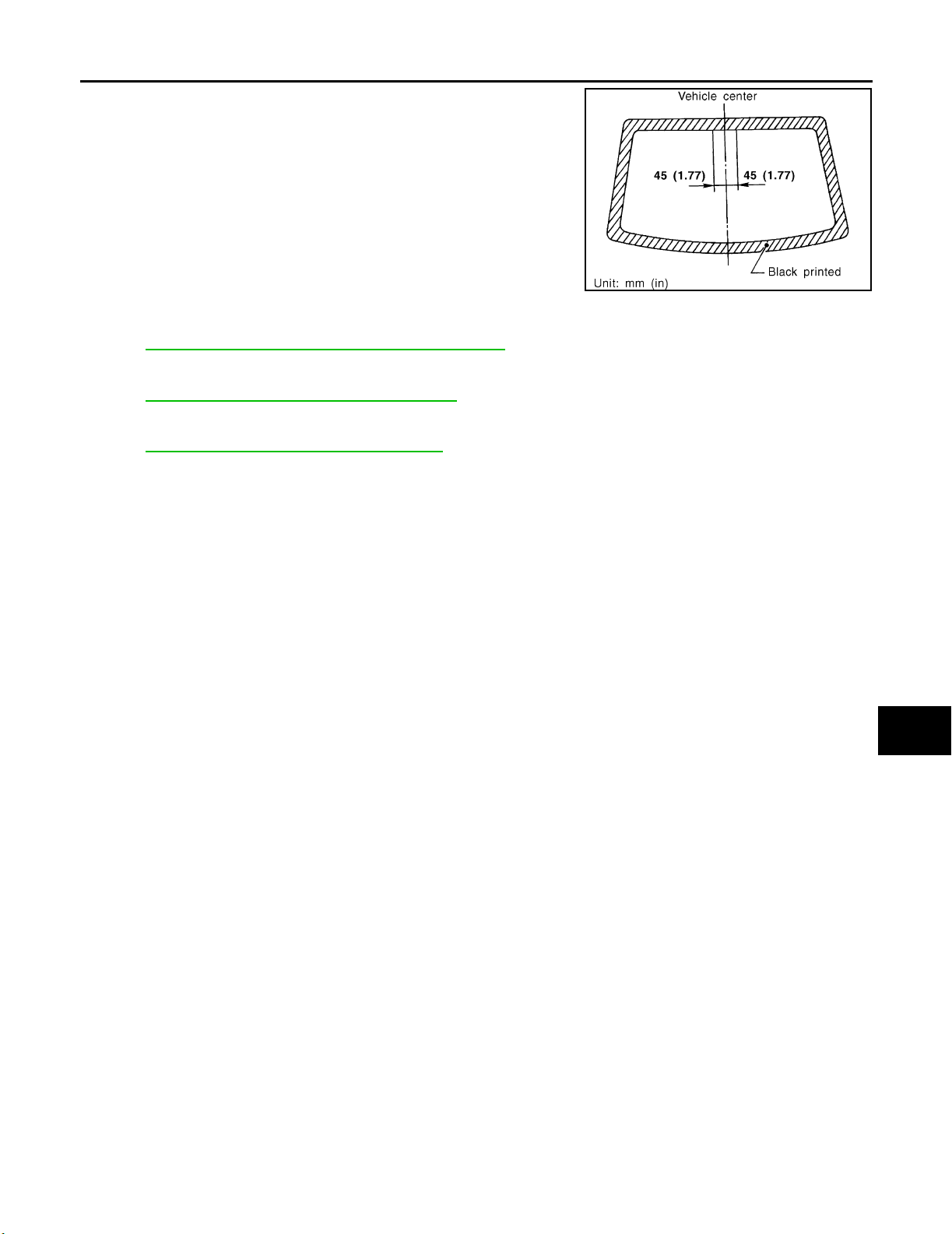
REAR WIPER AND WASHER SYSTEM
FRONT AND REAR WASHER MOTOR
Refer to WW-30, "FRONT AND REAR WASHER MOTOR" .
WIPER AND WASHER SWITCH
Refer to WW-28, "WIPER AND WASHER SWITCH" .
A
B
C
WEL912A
D
E
WASHER FLUID RESERVOIR
Refer to WW-29, "WASHER FLUID RESERVOIR" .
F
G
H
I
J
WW
L
M
Revision: September 2005 2006 Xterra
WW-47
Page 55
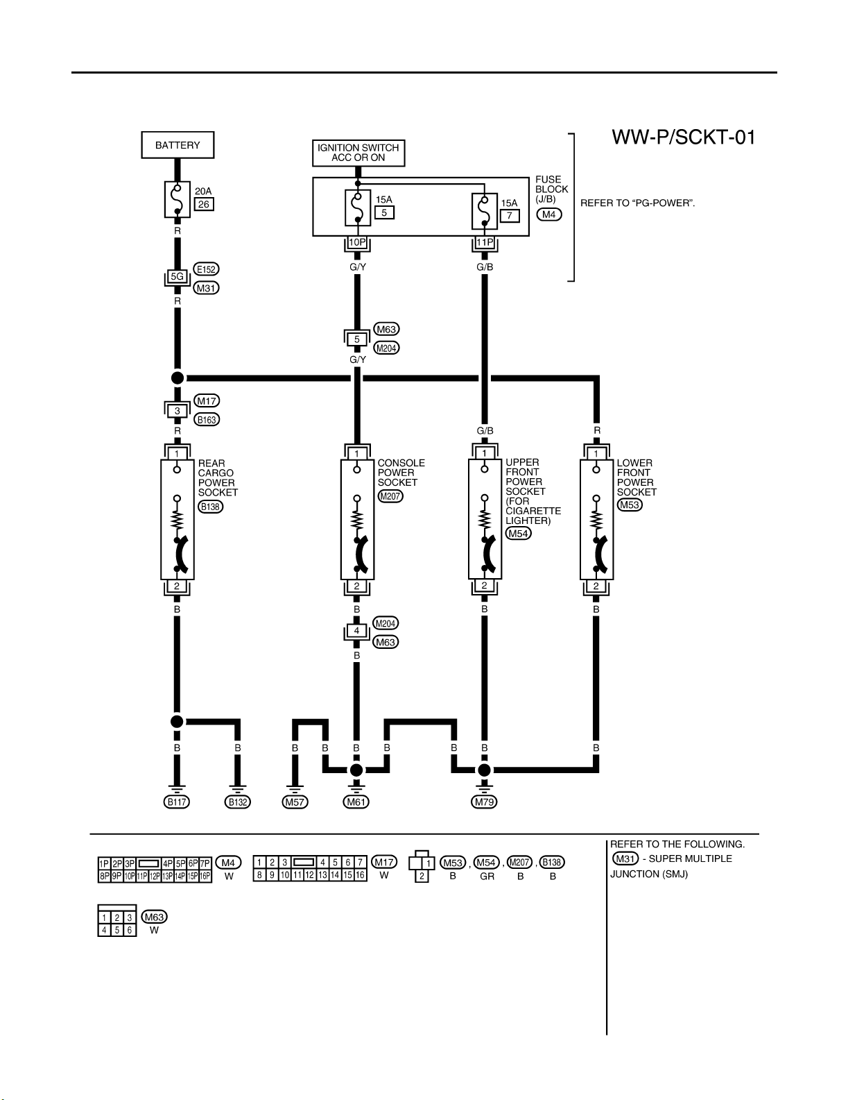
POWER SOCKET
POWER SOCKET PFP:253A2
Wiring Diagram — P/SCKT — EKS0 0DFM
WKWA4339E
Revision: September 2005 2006 Xterra
WW-48
Page 56
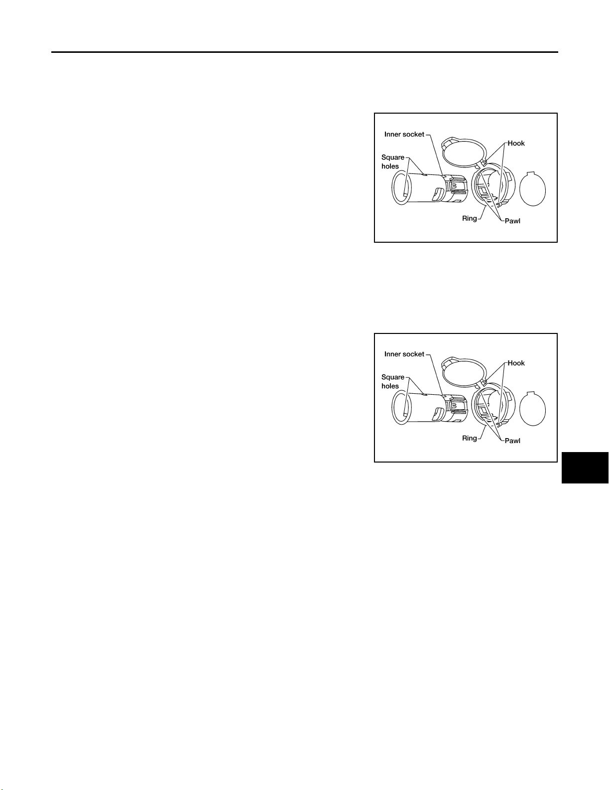
POWER SOCKET
Removal and Installation EKS0 0HO N
LOWER FRONT POWER SOCKET AND REAR CARGO POWER SOCKET
Removal
1. Disconnect battery negative terminal.
2. Remove inner socket from the ring, while pressing the hook on
the ring out from square hole.
3. Disconnect power socket connector.
4. Remove ring from power socket finisher while pressing pawls.
A
B
C
D
Installation
Installation is in the reverse order of removal.
UPPER FRONT POWER SOCKET (FOR CIGARETTE LIGHTER) AND CONSOLE POWER
SOCKET
Removal
1. Remove inner socket from the ring, while pressing the hook on
the ring out from square hole.
2. Disconnect power socket connector.
3. Remove ring from power socket finisher while pressing pawls.
Installation
Installation is in the reverse order of removal.
WKIA1035E
WKIA1035E
E
F
G
H
I
J
WW
L
Revision: September 2005 2006 Xterra
WW-49
M
Page 57
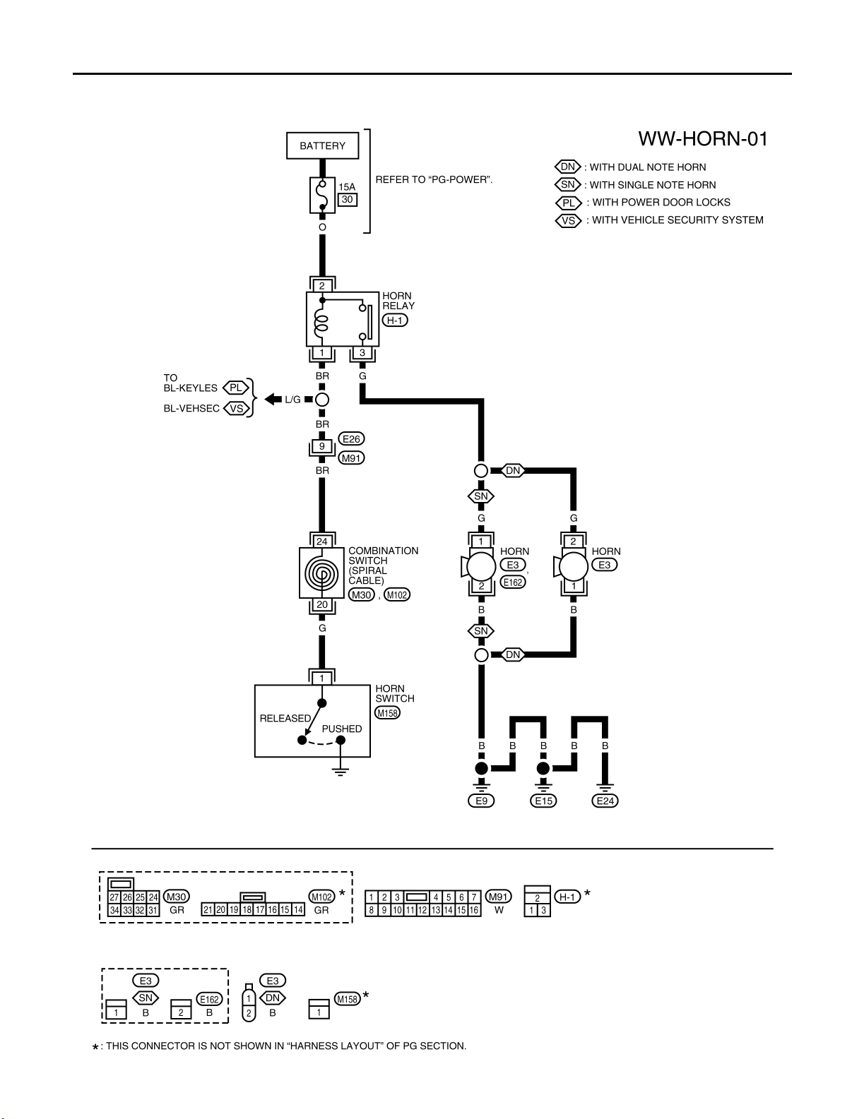
HORN
HORN PFP:25610
Wiring Diagram — HORN — EKS00DFO
WKWA4295E
Revision: September 2005 2006 Xterra
WW-50
Page 58
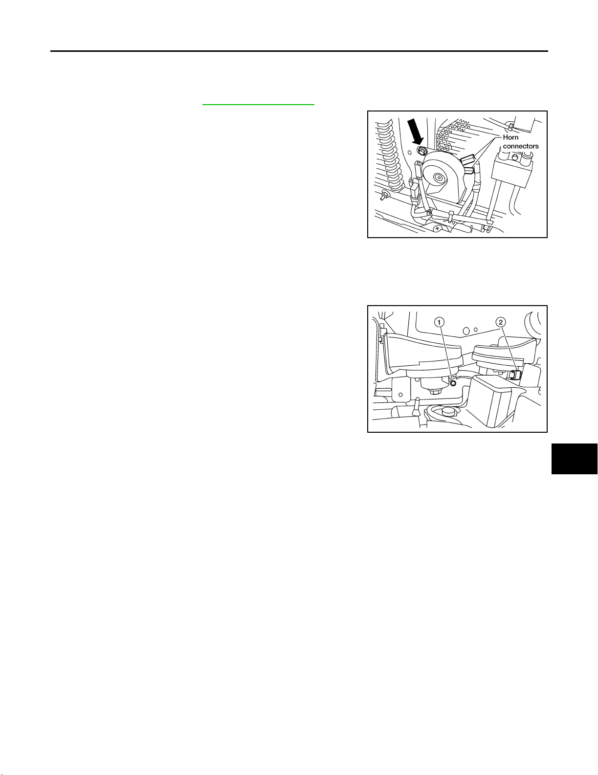
HORN
Removal and Installation EKS00HOE
HORN (SINGLE)
Removal
1. Remove front grille. Refer to EI-16, "FRONT GRILLE" .
2. Disconnect horn (single) connectors.
3. Remove horn (single) bolt and remove horn (single) from vehicle.
A
B
C
D
Installation
Installation is in the reverse order of removal.
HORN (DUAL)
Removal
1. Disconnect horn (duel) connector (2).
2. Remove horn (dual) bolt (1).
3. Remove horn (dual).
Installation
Installation is in the reverse order of removal.
LKIA05 46E
LKIA06 85E
E
F
G
H
I
J
WW
L
Revision: September 2005 2006 Xterra
WW-51
M
Page 59

HORN
Revision: September 2005 2006 Xterra
WW-52
Page 60

E SUSPENSION
A
B
SECTION WT
CONTENTS
PRECAUTIONS .......................................................... 2
Precautions for Supplemental Restraint System
(SRS) “AIR BAG” and “SEAT BELT PRE-TEN-
SIONER” .................................................................. 2
Precautions for work ................................................ 2
PREPARATION ........................................................... 3
Special Service Tool ................................................. 3
Commercial Service Tools ........................................ 3
NOISE, VIBRATION, AND HARSHNESS (NVH)
TROUBLESHOOTING ................................................ 4
NVH Troubleshooting Chart ..................................... 4
WHEEL ....................................................................... 5
Inspection ................................................................. 5
WHEEL AND TIRE ASSEMBLY ................................. 6
Balancing Wheels .................................................... 6
WHEEL BALANCE REMOVAL ............................. 6
WHEEL BALANCE INSTALLATION AND
ADJUSTMENT ...................................................... 6
Rotation .................................................................... 7
LOW TIRE PRESSURE WARNING SYSTEM ............ 8
System Components ................................................ 8
System Description .................................................. 8
TRANSMITTER ..................................................... 8
REMOTE KEYLESS ENTRY RECEIVER ............. 9
BCM (BODY CONTROL MODULE) ...................... 9
WARNING LAMP AND BUZZER .......................... 9
CAN COMMUNICATION .......................................... 10
System Description ................................................ 10
TROUBLE DIAGNOSES ...........................................11
Wiring Diagram — T/WARN — ............................... 11
Ter mi na l an d Re fer en ce Va lu e (B CM ) . ... ... .. .. . .. .. .... 12
ID Registration Procedure ...................................... 12
ID REGISTRATION WITH TRANSMITTER
ACTIVATION TOOL ............................................ 12
ID REGISTRATION WITHOUT TRANSMITTER
ACTIVATION TOOL ............................................ 14
Transmitter Wake Up Operation ............................. 16
WITH TRANSMITTER ACTIVATION TOOL ........ 16
CONSULT-II Function (BCM) ................................. 17
ROAD WHEELS & TIRES
Self-Diagnosis ........................................................ 18
DESCRIPTION .................................................... 18
FUNCTION .......................................................... 18
............................................................................ 18
How to Perform Trouble Diagnosis for Quick and
Accurate Repair ...................................................... 20
INTRODUCTION ................................................. 20
WORK FLOW ...................................................... 20
Preliminary Check .................................................. 21
Malfunction Code/Symptom Chart .......................... 22
TROUBLE DIAGNOSIS FOR SELF-DIAGNOSTIC
ITEMS ........................................................................ 24
Inspection 1: Transmitter or Control Unit (BCM) ..... 24
MALFUNCTION CODE NO. 21, 22, 23 OR 24 ... 24
Inspection 2: Transmitter - 1 ................................... 24
MALFUNCTION CODE NO. 31, 32, 33, 34, 41,
42, 43, 44, 45, 46, 47 OR 48 ............................... 24
Inspection 3: Transmitter - 2 ................................... 25
MALFUNCTION CODE NO. 35, 36, 37 OR 38 ... 25
Inspection 4: Vehicle Speed Signal ........................ 26
MALFUNCTION CODE NO. 52 ........................... 26
TROUBLE DIAGNOSIS FOR SYMPTOMS .............. 27
Inspection 1: Warning Lamp Does Not Come On
When Ignition Switch Is Turned On ........................ 27
Inspection 2: Warning Lamp Stays On When Ignition
Switch Is Turned On ............................................... 28
Inspection 3: Warning Lamp Flashes When Ignition
Switch Is Turned On ............................................... 30
Inspection 4: Hazard Warning Lamp Flashes When
Ignition Switch Is Turned On .................................. 31
Inspection 5: ID Registration Cannot Be Completed ... 31
REMOVAL AND INSTALLATION ............................. 32
Tran smitter (Pressure Sensor) ............................... 32
REMOVAL ........................................................... 32
INSTALLATION ................................................... 32
SERVICE DATA AND SPECIFICATIONS (SDS) ...... 34
Road Wheel ............................................................ 34
Tire ......................................................................... 34
C
D
WT
F
G
H
I
J
K
L
M
Revision: September 2005 2006 Xterra
WT-1
Page 61

PRECAUTIONS
PRECAUTIONS PFP:00001
Precautions for Supplemental Restraint System (SRS) “AIR BAG” and “SEAT
BELT PRE-TENSIONER”
The Supplemental Restraint System such as “AIR BAG” and “SEAT BELT PRE-TENSIONER”, used along
with a front seat belt, helps to reduce the risk or severity of injury to the driver and front passenger for certain
types of collision. This system includes seat belt switch inputs and dual stage front air bag modules. The SRS
system uses the seat belt switches to determine the front air bag deployment, and may only deploy one front
air bag, depending on the severity of a collision and whether the front occupants are belted or unbelted.
Information necessary to service the system safely is included in the SRS and SB section of this Service Manual.
WARNING:
● To a v oid r e nde rin g t he SRS i n ope r ati v e, wh ich co uld in crea s e the ri sk of per son al inj ury or de ath
in the event of a collision which would result in air bag inflation, all maintenance must be performed by an authorized NISSAN/INFINITI dealer.
● Improper maintenance, including incorrect removal and installation of the SRS, can lead to per-
sonal injury caused by unintentional activation of the system. For removal of Spiral Cable and Air
Bag Module, see the SRS section.
● Do not use electrical test equipment on any circuit related to the SRS unless instructed to in this
Service Manual. SRS wiring harnesses can be identified by yellow and/or orange harnesses or
harness connectors.
EES002C1
Precautions for work EES002C2
● After removing and installing the opening/closing parts, be sure to carry out fitting adjustments to check
their operation.
● Check the lubrication level, damage, and wear of each part. If necessary, grease or replace it.
Revision: September 2005 2006 Xterra
WT-2
Page 62
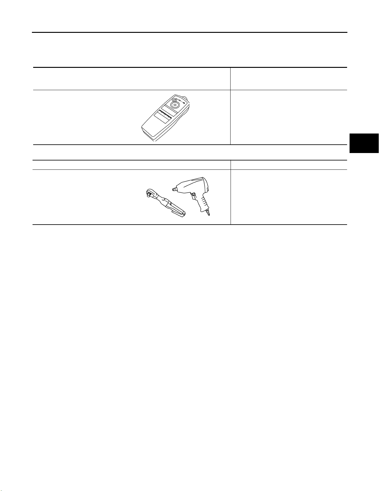
PREPARATION
PREPARATION PFP:00002
Special Service Tool EES001RB
The actual shapes of Kent-Moore tools may differ from those of special service tools illustrated here.
Tool number
(Kent-Moore No.)
Tool name
KV991B1000
(J-45295)
Transmitter activation tool
Description
ID registration
A
B
C
D
LEIA0035E
Commercial Service Tools EES001RC
Tool name Description
Power tool Removing wheel nuts
PBIC0190E
WT
F
G
H
I
J
K
L
Revision: September 2005 2006 Xterra
WT-3
M
Page 63
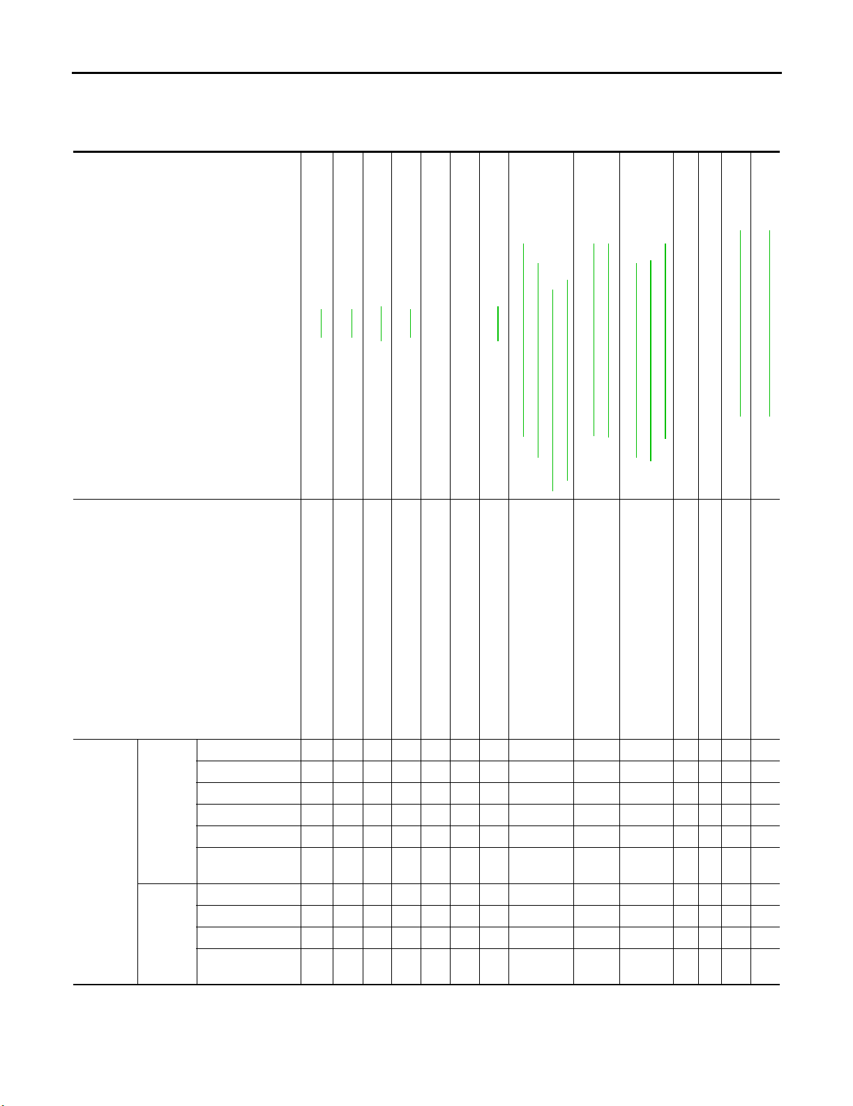
NOISE, VIBRATION, AND HARSHNESS (NVH) TROUBLESHOOTING
NOISE, VIBRATION, AND HARSHNESS (NVH) TROUBLESHOOTING PFP:00003
NVH Troubleshooting Chart EES001RD
Use chart below to help you find the cause of the symptom. If necessary, repair or replace these parts.
Reference page
Possible cause and SUSPECTED
PA RT S
Noise ЧЧЧЧЧЧ × × × × ××
Shake ЧЧЧЧЧ × × × × ××
Vibration ××××××
TIRES
Symptom
ROAD
WHEEL
×: Applicable
Shimmy ЧЧЧЧЧЧЧ × × × ××
Shudder ЧЧЧЧЧ × × × × ××
Poor quality ride
or handling
Noise ×× × × × × ×××
Shake ×× × × × ×××
Shimmy, shudder ×× × × × ×××
Poor quality ride
or handling
—
WT-5
WT-6
Out-of-round
Imbalance
ЧЧЧЧЧ × × × ×
×× × × × ×
WT-7
WT-34
Incorrect tire pressure
Uneven tire wear
—
WT-34
NVH Troubleshooting Chart" (FAX)
NVH Troubleshooting Chart" (FSU)
NVH Troubleshooting Chart" (RFD, C200),
NVH Troubleshooting Chart" (RFD, M226 with LD)
FFD-6, "NVH Troubleshooting Chart" (FFD)
RFD-8, "
Deformation or damage
Non-uniformity
Incorrect tire size
FRONT AND REAR FINAL DRIVE
FAX-4, "
NVH Troubleshooting Chart" (RFD, M226 without LD),
RFD-42, "
FSU-4, "
RFD-77, "
FRONT AXLE AND FRONT SUSPENSION
NVH Troubleshooting Chart" (RSU)
NVH Troubleshooting Chart" (RAX, M226),
NVH Troubleshooting Chart" (RAX, C200),
RSU-4, "
RAX-5, "
RAX-17, "
Refer to TIRES in this chart.
Refer to ROAD WHEEL in this chart.
REAR AXLE AND REAR SUSPENSION
TIRES
ROAD WHEEL
NVH Troubleshooting Chart"
PS-5, "NVH Troubleshooting Chart"
BR-5, "
BRAKE
STEERING
Revision: September 2005 2006 Xterra
WT-4
Page 64
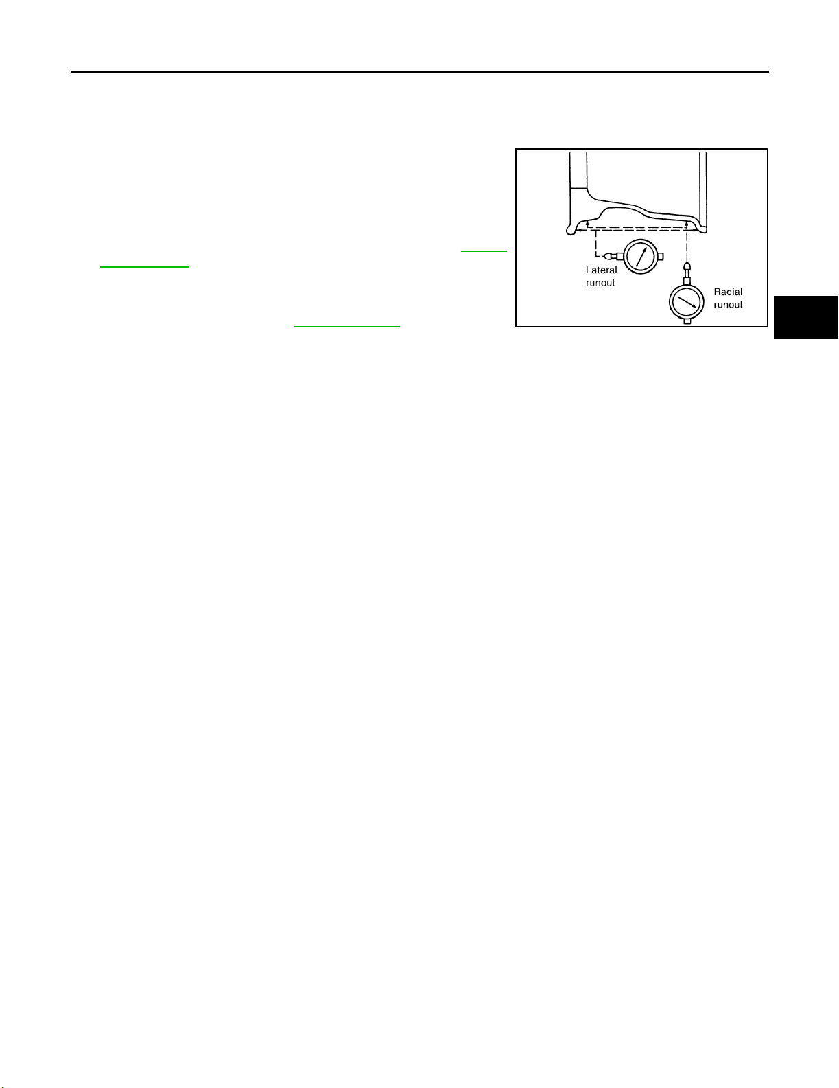
WHEEL
WHEEL PFP:40300
Inspection EES001RE
1. Remove wheel and tire using power tool.
2. Check tires for wear and improper inflation.
3. Check wheels for deformation, cracks and other damage. If
deformed, remove wheel and check wheel runout.
a. Remove tire from wheel and mount wheel on a tire balance
machine.
b. Set dial indicator as shown in the illustration. Refer to WT-34,
"Road Wheel" .
4. Check front wheel bearings for looseness.
5. Check front suspension for looseness.
6. Install wheel and tire. Refer to WT-7, "
Rotation" .
SFA975 B
A
B
C
D
WT
F
G
M
H
I
J
K
L
Revision: September 2005 2006 Xterra
WT-5
Page 65
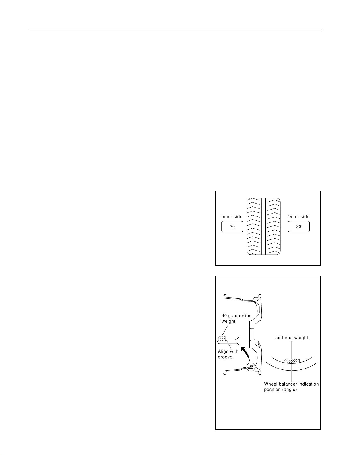
WHEEL AND TIRE ASSEMBLY
WHEEL AND TIRE ASSEMBLY PFP:40300
Balancing Wheels EES001RF
WHEEL BALANCE REMOVAL
1. Remove wheel and tire using power tool.
2. Using releasing agent, remove double-faced adhesive tape from the wheel.
CAUTION:
● Be careful not to scratch the wheel during removal.
● After removing double-faced adhesive tape, wipe clean traces of releasing agent from the
wheel.
WHEEL BALANCE INSTALLATION AND ADJUSTMENT
● If a tire balance machine has adhesion balance weight mode settings and drive-in weight mode setting,
select and adjust a drive-in weight mode suitable for wheels.
1. Set wheel on wheel balancer using the center hole as a guide. Start the tire balance machine.
2. When inner and outer imbalance values are shown on the wheel balancer indicator, multiply outer imbalance value by 1.6 to determine balance weight that should be used. Select the outer balance weight with
a value closest to the calculated value and install it to the designated outer position of, or at the designated angle in relation to the road wheel.
CAUTION:
● Do not install the inner balance weight before installing the outer balance weight.
● Before installing the balance weight, be sure to clean the mating surface of the wheel.
Indicated imbalance value × 5/3 = balance weight to be installed
Calculation example:
23 g (0.81 oz) × 5/3 = 38.33 g (1.35 oz) = 40 g (1.41 oz) balance
weight (closer to calculated balance weight value)
Note that balance weight value must be closer to the calculated
balance weight value.
Example:
37.4 g = 35 g (1.23 oz)
37.5 g = 40 g (1.41 oz)
a. Install balance weight in the position shown.
b. When installing balance weight to wheels, set it into the grooved
area on the inner wall of the wheel as shown so that the balance
weight center is aligned with the wheel balancer indication position (angle).
CAUTION:
● Always use Genuine NISSAN adhesion balance weights.
● Balance weights are not reusable; always replace with
new ones.
● Do not install more than three sheets of balance weights.
SMA0 54D
WDIA0060E
Revision: September 2005 2006 Xterra
WT-6
Page 66
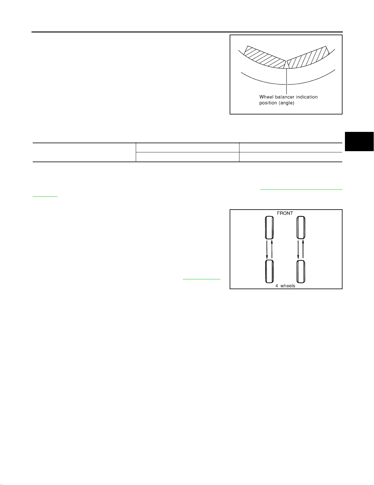
WHEEL AND TIRE ASSEMBLY
c. If calculated balance weight value exceeds 50 g (1.76 oz), install
two balance weight sheets in line with each other as shown.
CAUTION:
Do not install one balance weight sheet on top of another.
3. Start wheel balancer again.
4. Install drive-in balance weight on inner side of road wheel in the
wheel balancer indication position (angle).
CAUTION:
Do not install more than two balance weights.
5. Start wheel balancer. Make sure that inner and outer residual
imbalance values are 5g (0.18 oz) each or below.
● If either residual imbalance value exceeds 5 g (0.18 oz), repeat installation procedures.
Wheel balance (Maximum allowable imbalance):
Maximum allowable imbalance
Dynamic (At rim flange) 5 g (0.18 oz) (one side)
Static 10 g (0.3 5 oz)
A
B
C
SMA0 56D
D
WT
Rotation EES001RG
NOTE:
Follow the maintenance schedule for tire rotation service intervals. Refer to MA-5, "
NANCE" .
1. Remove wheels and tires.
2. Rotate wheels and tires on each side from front to back as
shown. Do not include the spare wheel and tire when rotating
the wheels and tires.
Wheel nut : 133 N·m (14 kg-m, 98 ft-lb)
CAUTION:
When installing wheels and tires, tighten them diagonally
by dividing the work two to three times in order to prevent
the wheels from developing any distortion.
3. Adjust the tire pressure to specification. Refer to WT-34, "
Tire" .
4. After the wheel and tire rotation, retighten the wheel nuts after
the vehicle has been driven for 1,000 km (600 miles), and also
after any wheel and tire has been installed, such as after repairing a flat tire.
GENERAL MAINTE-
SMA8 29C
F
G
H
I
J
K
L
M
Revision: September 2005 2006 Xterra
WT-7
Page 67
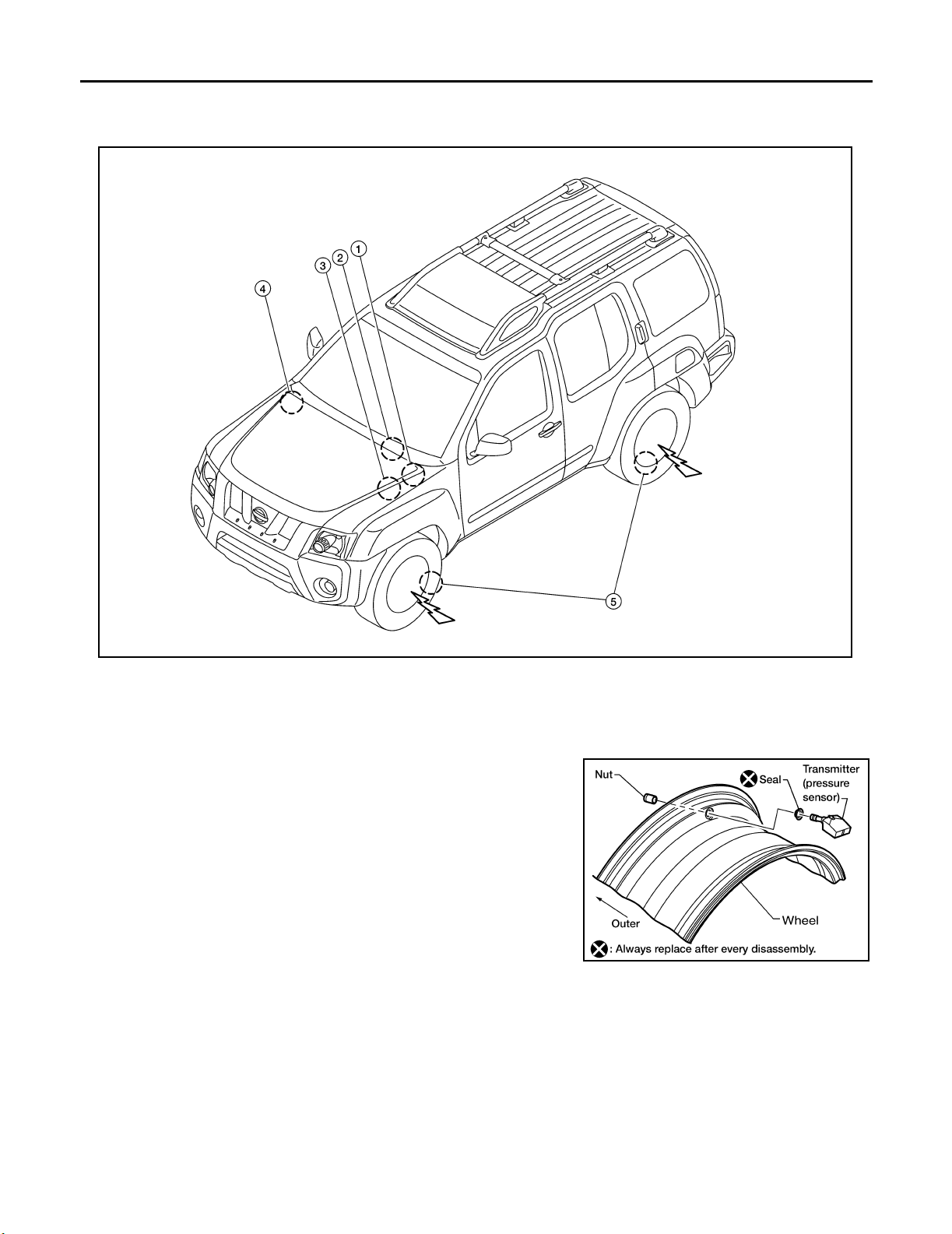
LOW TIRE PRESSURE WARNING SYSTEM
LOW TIRE PRESSURE WARNING SYSTEM PFP:40300
System Components EES001UZ
WEIA0135E
1. BCM 2. Combination meter 3. Tire pressure warning check connector
4. Remote keyless entry receiver 5. Transmitters
System Description EE S001 V0
TRANSMITTER
A sensor-transmitter integrated with a valve is installed on a wheel,
and transmits a detected air pressure signal in the form of a radio
wave.
WEIA0137E
Revision: September 2005 2006 Xterra
WT-8
Page 68
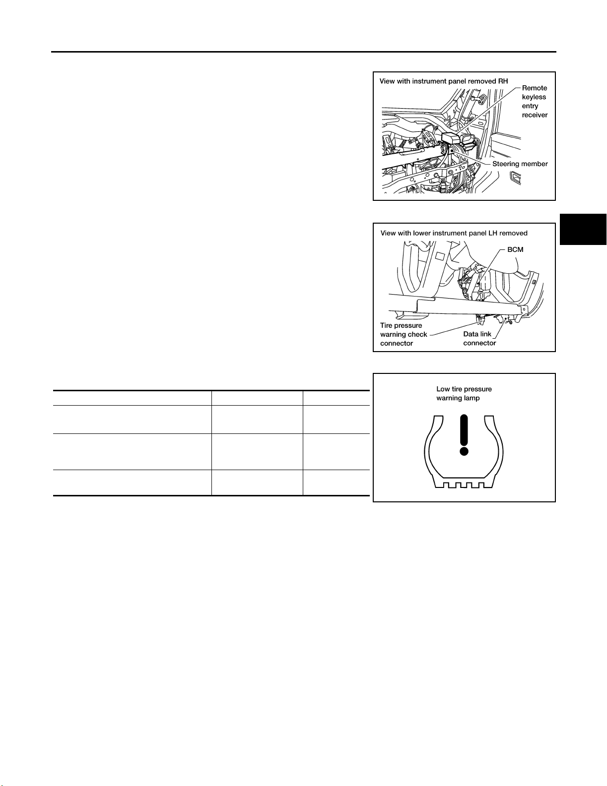
LOW TIRE PRESSURE WARNING SYSTEM
REMOTE KEYLESS ENTRY RECEIVER
Receives the air pressure signal transmitted by the transmitter in
each wheel.
A
B
C
BCM (BODY CONTROL MODULE)
Reads the air pressure signal received by the remote keyless entry
receiver, and controls the warning lamp and the buzzer operations
as shown below. It also has a judgement function to detect a system
malfunction.
WARNING LAMP AND BUZZER
Indicates low tire pressure or system malfunction.
Condition Warning lamp Buzzer
2
Less than 193 kPa (2.0 kg/cm
[Flat tire]
System malfunction
System normal
, 28 psi)
ON OFF
After key ON, flashes
once per second for 1
minute, then stays ON
ON for 1 second after
ignition ON
OFF
OFF
LEIA00 69E
WEIA0126E
LEIA00 55E
D
WT
F
G
H
I
J
K
L
Revision: September 2005 2006 Xterra
WT-9
M
Page 69

CAN COMMUNICATION
CAN COMMUNICATION PFP:23710
System Description EES001RJ
Refer to LAN-21, "CAN COMMUNICATION" .
Revision: September 2005 2006 Xterra
WT-10
Page 70
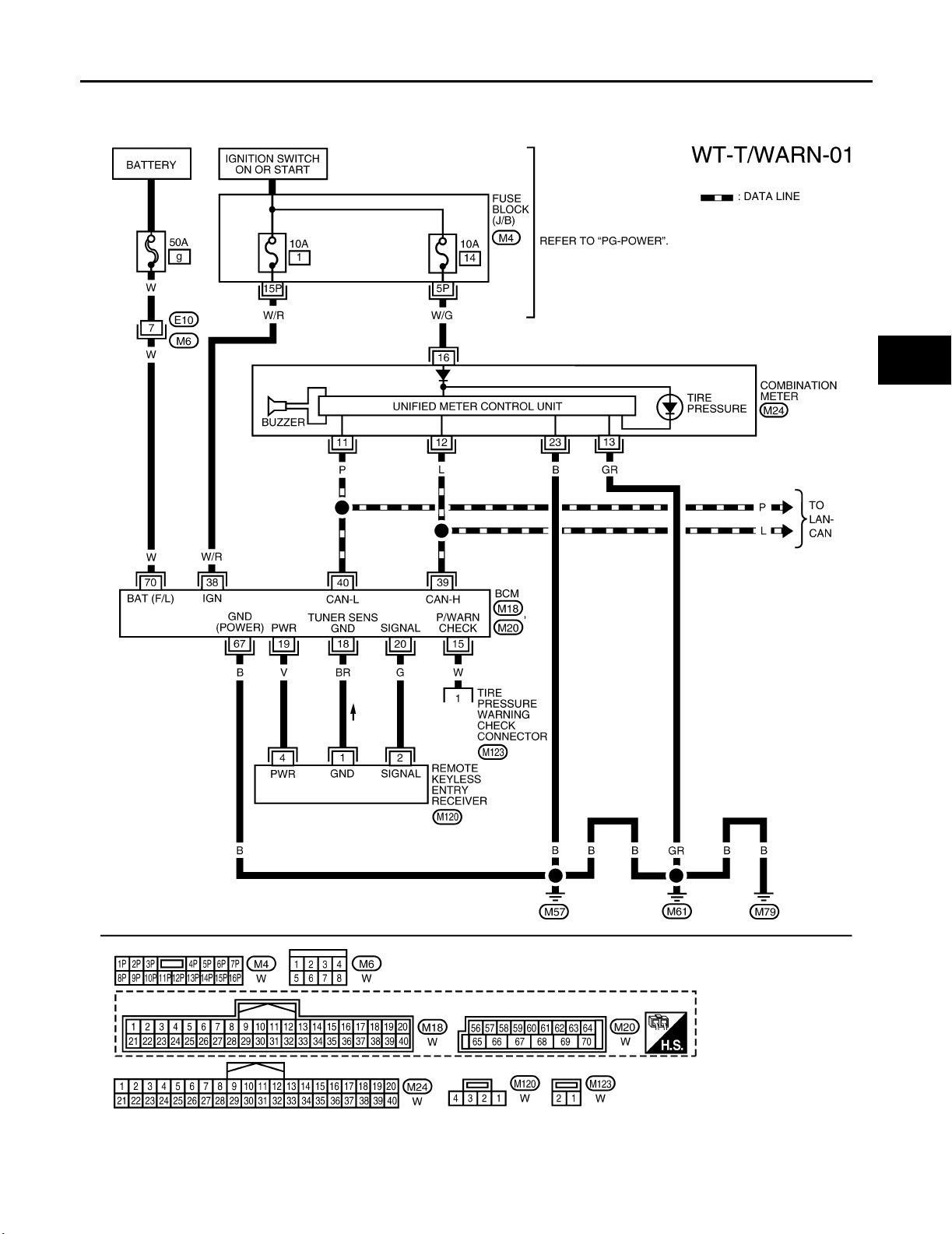
TROUBLE DIAGNOSES
TROUBLE DIAGNOSES PFP:00004
Wiring Diagram — T/WARN — EES001V1
A
B
C
D
WT
F
G
M
H
I
J
K
L
WEWA0062E
Revision: September 2005 2006 Xterra
WT-11
Page 71
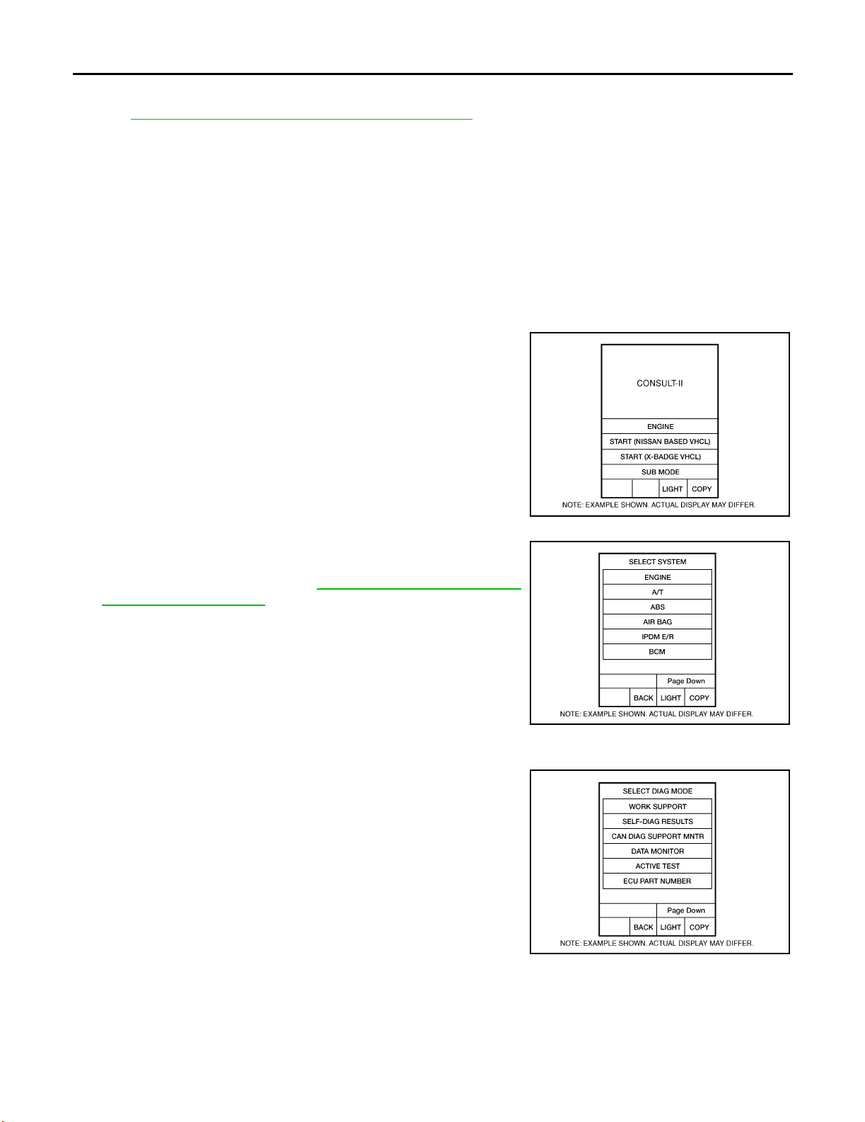
TROUBLE DIAGNOSES
Terminal and Referenc e Valu e (BCM) EES0 01V 2
Refer to BCS-12, "Ter min al s an d Re fe re nce Va lu es fo r BC M" .
ID Registration Procedure EES 001 V3
ID REGISTRATION WITH TRANSMITTER ACTIVATION TOOL
NOTE:
This procedure must be done after replacement of a low tire pressure warning transmitter or BCM.
New replacement transmitters are provided "asleep" and must first be "woken up" using Transmitter
Activation Tool J-45295 before ID registration can be performed.
CAUTION:
If CONSULT-II is used with no connection of CONSULT-II CONVERTER, malfunction might be detected
during self-diagnosis depending on control unit which carries out CAN communication.
1. With the ignition switch OFF, connect CONSULT-II and CONSULT-II CONVERTER to the data link connector, then turn the ignition switch ON.
2. Select "START (NISSAN BASED VHCL)".
3. Touch “BCM” on "SELECT SYSTEM" screen.
NOTE:
If "BCM" is not indicated, go to GI-41, "
CONSULT-II Data Link
Connector (DLC) Circuit" .
4. Select “AIR PRESSURE MONITOR” on "SELECT TEST ITEM" screen.
5. Select “WORK SUPPORT” on "SELECT DIAG MODE" screen,
and select "ID REGIST".
BCIA0 029E
BCIA0 030E
BCIA0 031E
Revision: September 2005 2006 Xterra
WT-12
Page 72
TROUBLE DIAGNOSES
6. With the transmitter activation tool (J-45295) pushed against the
front left transmitter position of the tire air valve, press the button
for 5 seconds.
Tool num ber : — (J-4 529 5 )
SEIA 0101E
7. Register the IDs in order from FR LH, FR RH, RR RH and RR LH. When ID registration of each wheel has
been completed, a buzzer sounds and the warning lamp flashes.
A
B
C
D
Activation tire position Buzzer Hazard warning lamp CONSULT-II
1Front LH Once
2Front RH 2 times
3Rear RH 3 times
4Rear LH 4 times
2 times flashing
“YET”
↓
“DONE”
8. After completing all ID registrations, press “END” to complete the procedure.
NOTE:
Be sure to register the IDs in order from FR LH, FR RH, RR RH, to RR LH, or the self-diagnostic results display will not function properly.
WT
F
G
H
I
J
K
L
Revision: September 2005 2006 Xterra
WT-13
M
Page 73
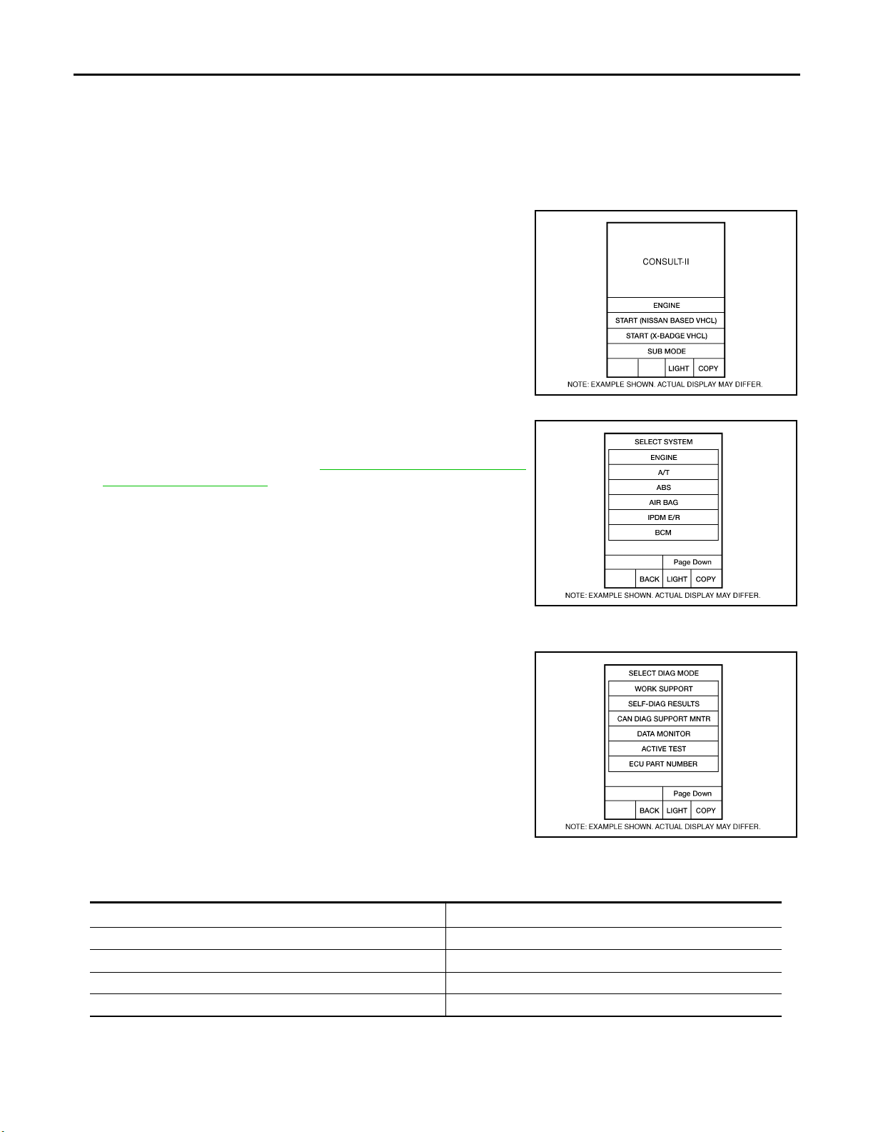
TROUBLE DIAGNOSES
ID REGISTRATION WITHOUT TRANSMITTER ACTIVATION TOOL
NOTE:
This procedure must be done after replacement of a low tire pressure warning transmitter or BCM.
New replacement transmitters are provided "asleep" and must first be "woken up" using Transmitter
Activation Tool J-45295 before ID registration can be performed.
1. With the ignition switch OFF, connect CONSULT-II and CONSULT-II CONVERTER to the data link connector, then turn the ignition switch ON.
2. Select "START (NISSAN BASED VHCL)".
BCIA0 029E
3. Touch “BCM” on "SELECT SYSTEM" screen.
NOTE:
If "BCM" is not indicated, go to GI-41, "
Connector (DLC) Circuit" .
CONSULT-II Data Link
BCIA0 030E
4. Select “AIR PRESSURE MONITOR” on "SELECT TEST ITEM" screen.
5. Select “WORK SUPPORT” on "SELECT DIAG MODE" screen,
and select "ID REGIST".
BCIA0 031E
6. Adjust the tire pressure to the values shown in the table below for ID registration, and drive the vehicle at
15 km/h (9.4 MPH) or more for a few minutes.
Tire positi on
Front – Left 250 (2.5, 36)
Front – Right 230 (2.3, 33)
Rear – Right 210 (2.1, 30)
Rear – Left 190 (1.9, 27)
Tire pressure kPa (k g/cm2 , psi)
7. After completing all ID registrations, press “END” to complete the procedure.
Revision: September 2005 2006 Xterra
WT-14
Page 74

TROUBLE DIAGNOSES
Activation tire position CONSULT-II
Front LH
Front RH
Rear RH
Rear LH
8. Inflate all tires to proper pressure. Refer to WT-34, "Tire" .
“YET”
↓
“DONE”
A
B
C
D
WT
F
G
H
M
I
J
K
L
Revision: September 2005 2006 Xterra
WT-15
Page 75
TROUBLE DIAGNOSES
Transmitter Wake Up Operation EES0 01V 4
WITH TRANSMITTER ACTIVATION TOOL
NOTE:
This procedure must be done after replacement of a low tire pressure warning transmitter or BCM.
New replacement transmitters are provided "asleep" and must first be "woken up" using Transmitter
Activation Tool J-45295 before ID registration can be performed.
1. With the transmitter activation tool (J-45295) pushed against the
front left transmitter, press the button for 5 seconds.
Tool number : — (J-4529 5)
● With ignition switch ON, as the warning lamp flashes per the
following diagram, the respective transmitter then must be
woken up.
SEIA 0101E
2. When the BCM finishes assigning each tire ID, the BCM flashes the hazard warning lamps and trailer
flasher lamps (if equipped) and sends flashing indicator status by CAN according to the following time
chart. Please see trailer flasher specification details of trailer flashing lamps since the BCM controls trailer
flasher lamps as brake lamps. Refer to LT-9 6, "
TRAILER TOW" .
LEIA00 59E
3. After completing wake up of all transmitters, make sure low tire pressure warning lamp goes out.
Revision: September 2005 2006 Xterra
WT-16
Page 76
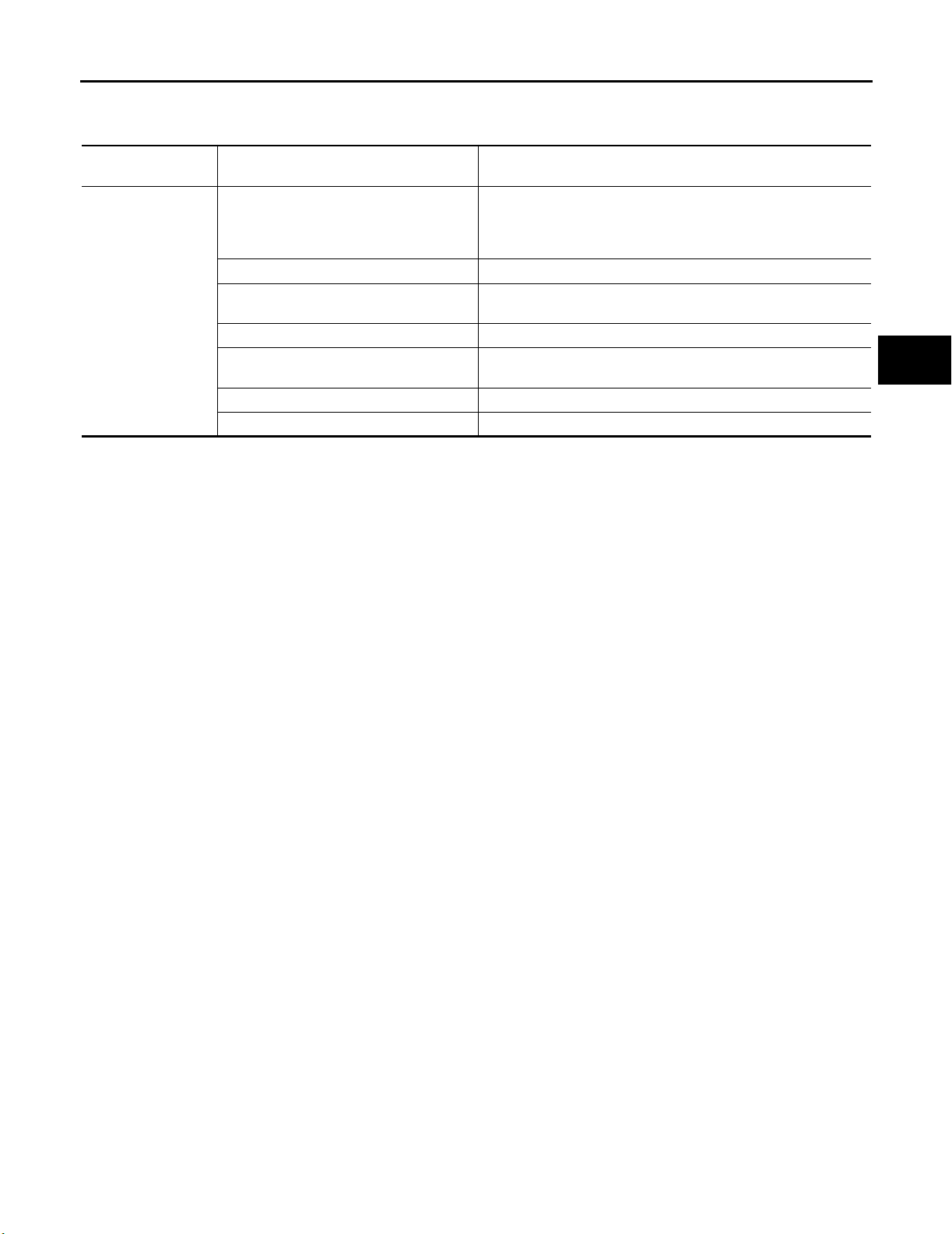
TROUBLE DIAGNOSES
CONSULT-II Function (BCM) EES001V5
CONSULT-II can display each diagnostic item using the diagnostic test modes shown following.
A
BCM
diagnostic test item
Inspection by part
Diagnostic mode Description
Supports inspections and adjustments. Commands are transmit-
WORK SUPPORT
DATA MONITOR Displays BCM input/output data in real time.
ACTIVE TEST
SELF-DIAG RESULTS Displays BCM self-diagnosis results.
CAN DIAG SUPPORT MNTR
ECU PART NUMBER BCM part number can be read.
CONFIGURATION Performs BCM configuration read/write functions.
ted to the BCM for setting the status suitable for required operation, input/output signals are received from the BCM and received
data is displayed.
Operation of electrical loads can be checked by sending drive signal to them.
The result of transmit/receive diagnosis of CAN communication
can be read.
B
C
D
WT
F
G
H
M
I
J
K
L
Revision: September 2005 2006 Xterra
WT-17
Page 77
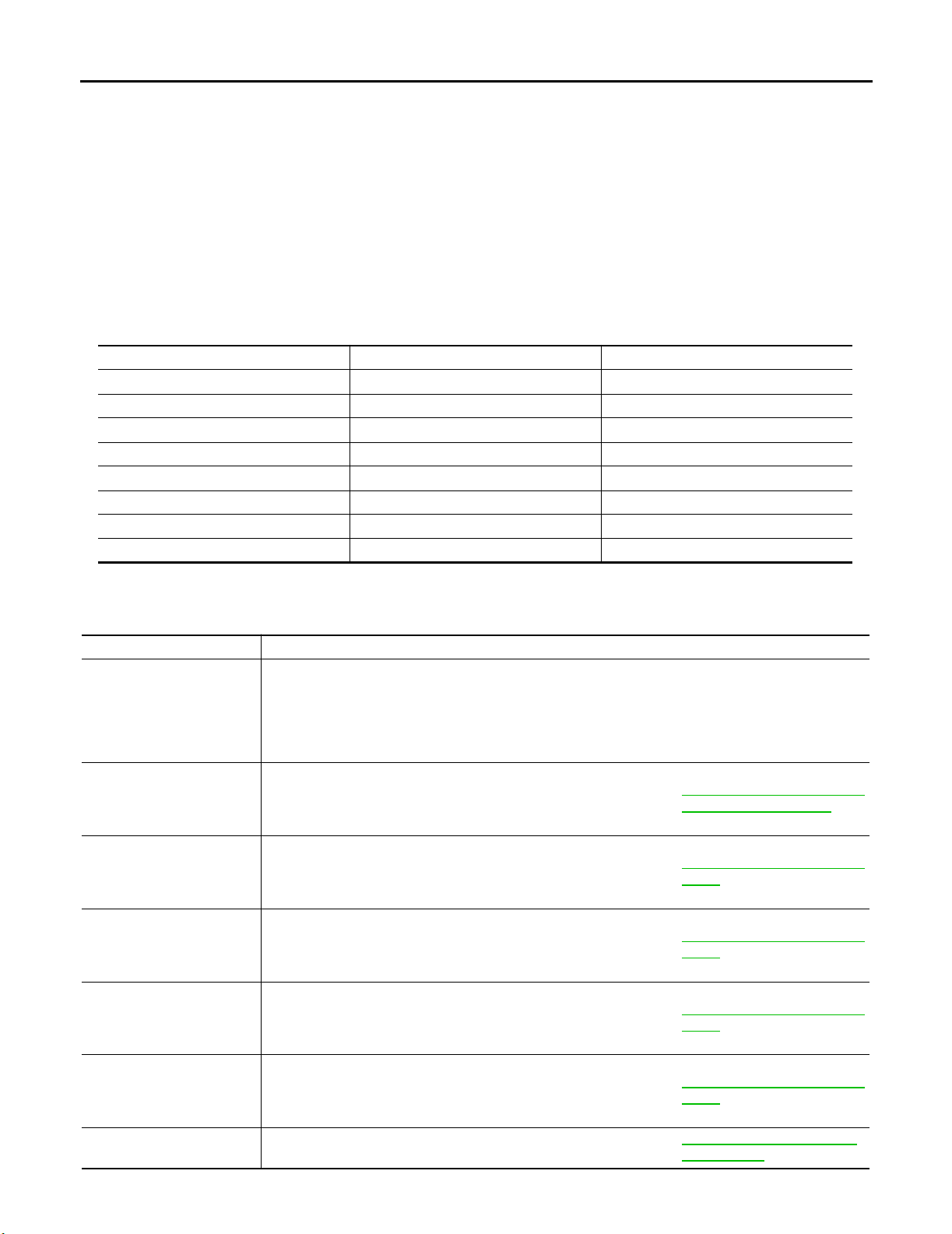
TROUBLE DIAGNOSES
Self-Diagnosis EES0 01V 6
DESCRIPTION
During driving the low tire pressure warning system receives the signal transmitted from the transmitter
installed in each wheel, and gives alarms when the tire pressure becomes low. The control unit (BCM) for this
system has pressure judgement and trouble diagnosis functions.
FUNCTION
When the low tire pressure warning system detects low inflation pressure or another unusual symptom, the
warning lamp in the combination meter comes on. To start the self-diagnostic results mode, ground the tire
pressure warning check terminal. The malfunction location is indicated by the warning lamp flashing and the
buzzer sounds.
CONSULT-II Application to Low Tire Pressure Warning System
ITEM SELF-DIAGNOSTIC RESULTS DATA MONITOR
Front - Left transmitter ××
Front - Right transmitter ××
Rear - Left transmitter ××
Rear - Right transmitter ××
Warning lamp — ×
Vehi cle sp ee d ××
Buzzer (in combination meter) — ×
CAN Communication ××
×: Applicable
–: Not applicable
Self-Diagnostic Results Mode
Diagnostic item Diagnostic item is detected when ··· Reference page
FLAT - TIRE - FL
FLAT - TIRE - FR
FLAT - TIRE - RR
FLAT - TIRE - RL
[NO-DATA] - FL
[NO-DATA] - FR
[NO-DATA] - RR
[NO-DATA] - RL
[CHECKSUM- ERR] - FL
[CHECKSUM- ERR] - FR
[CHECKSUM- ERR] - RR
[CHECKSUM- ERR] - RL
[PRESSDATA- ERR] - FL
[PRESSDATA- ERR] - FR
[PRESSDATA- ERR] - RR
[PRESSDATA- ERR] - RL
[CODE- ERR] - FL
[CODE- ERR] - FR
[CODE- ERR] - RR
[CODE- ERR] - RL
[BATT - VOLT - LOW] - FL
[BATT - VOLT - LOW] - FR
[BATT - VOLT - LOW] - RR
[BATT - VOLT - LOW] - RL
VHCL_SPEED_SIG_ERR Vehicle speed signal is in error.
Front-left tire pressure drops to 193 kPa (2.0 kg/cm
Front-right tire pressure drops to 193 kPa (2.0 kg/cm
less
Rear-right tire pressure drops to 193 kPa (2.0 kg/cm
Rear-left tire pressure drops to 193 kPa (2.0 kg/cm
Data from front-left transmitter cannot be received.
Data from front-right transmitter cannot be received.
Data from rear-right transmitter cannot be received.
Data from rear-left transmitter cannot be received.
Checksum data from front-left transmitter is malfunctioning.
Checksum data from front-right transmitter is malfunctioning.
Checksum data from rear-right transmitter is malfunctioning.
Checksum data from rear-left transmitter is malfunctioning.
Air pressure data from front-left transmitter is malfunctioning.
Air pressure data from front-right transmitter is malfunctioning.
Air pressure data from rear-right transmitter is malfunctioning.
Air pressure data from rear-left transmitter is malfunctioning.
Function code data from front-left transmitter is malfunctioning.
Function code data from front-right transmitter is malfunctioning.
Function code data from rear-right transmitter is malfunctioning.
Function code data from rear-left transmitter is malfunctioning.
Battery voltage of front-left transmitter drops.
Battery voltage of front-right transmitter drops.
Battery voltage of rear-right transmitter drops.
Battery voltage of rear-left transmitter drops.
2
, 28 psi) or less
2
, 28 psi) or
2
, 28 psi) or less
2
, 28 psi) or less
—
WT-24, "
ter or Control Unit (BCM)"
WT-24, "
ter - 1"
WT-25, "
ter - 2"
WT-24, "
ter - 1"
WT-25, "
ter - 2"
WT-26, "
Speed Signal"
Inspection 1: Transmit-
Inspection 2: Transmit-
Inspection 3: Transmit-
Inspection 2: Transmit-
Inspection 3: Transmit-
Inspection 4: Vehicle
Revision: September 2005 2006 Xterra
WT-18
Page 78
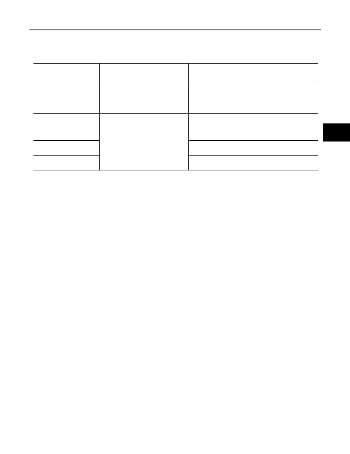
TROUBLE DIAGNOSES
NOTE:
Before performing the self-diagnosis, be sure to register the ID or the actual malfunction location may be different from that displayed on
CONSULT-II.
Data Monitor Mode
MONITOR CONDITION SPECIFICATION
VHCL SPEED Drive vehicle. Vehicle speed (km/h or MPH)
AIR PRESS FL
AIR PRESS FR
AIR PRESS RR
AIR PRESS RL
ID REGST FL1
ID REGST FR1
ID REGST RR1
ID REGST RL1
WARN ING L AMP
BUZZER
NOTE:
Before performing the self-diagnosis, be sure to register the ID, or the actual malfunction location may be different from that displayed on
CONSULT-II.
● Drive vehicle for a few minutes.
or
● Ignition switch ON and activation tool
is transmitting activation signals.
Ignition switch ON
Tire pressure (kPa or psi)
Registration ID: DONE
No registration ID: YET
Low tire pressure warning lamp on: ON
Low tire pressure warning lamp off: OFF
Buzzer in combination meter on: ON
Buzzer in combination meter off: OFF
A
B
C
D
WT
F
G
M
H
I
J
K
L
Revision: September 2005 2006 Xterra
WT-19
Page 79
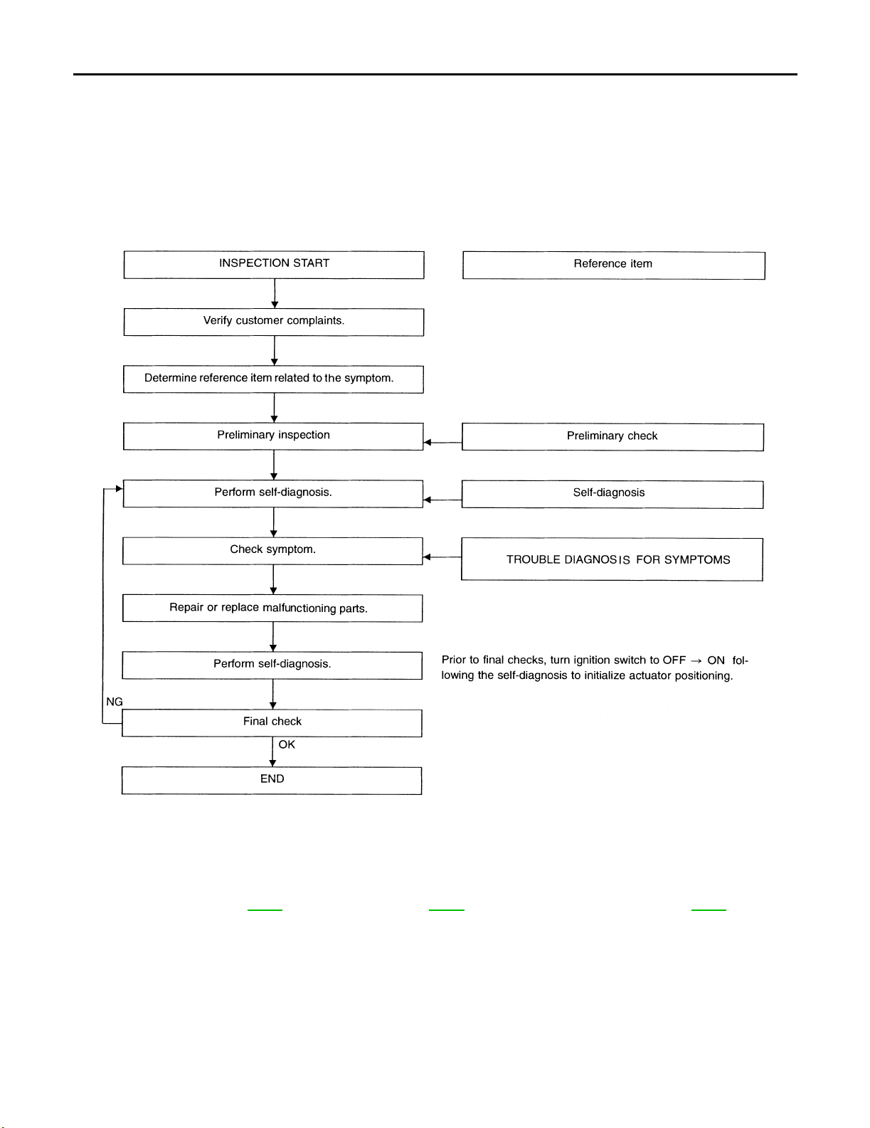
TROUBLE DIAGNOSES
How to Perform Trouble Diagnosis for Quick and Accurate Repair EES 001 V7
INTRODUCTION
● Before troubleshooting, verify customer complaints.
● If a vehicle malfunction is difficult to reproduce, harnesses, harness connectors or terminals may be mal-
functioning. Hold and shake these parts to make sure they are securely connected.
● When using a circuit tester to measure voltage or resistance of each circuit, be careful not to damage or
deform connector terminals.
WORK FLOW
SEIA 0100E
Preliminary check: WT-21 Self-diagnosis: WT-18 Trouble diagn os is for sympto ms: WT-27
Revision: September 2005 2006 Xterra
WT-20
Page 80
TROUBLE DIAGNOSES
Preliminary Check EES001V8
BASIC INSPECTION
1. CHECK ALL TIRE PRESSURES
Check all tire pressures. Refer to WT-34
OK or NG
OK >> GO TO 2.
NG >> Adjust tire pressure to specified value.
.
2. CHECK LOW TIRE PRESSURE WARNING LAMP ACTIVATION
Check low tire pressure warning lamp activation.
Does warning lamp activate for 1 second when ignition switch is turned ON?
YES >> GO TO 3.
NO >> Check fuse and combination meter.
A
B
C
D
WT
3. CHECK CONNECTOR
1. Disconnect BCM harness connectors.
2. Check terminals for damage or loose connection.
3. Reconnect harness connectors.
OK or NG
OK >> GO TO 4.
NG >> Repair or replace damaged parts.
4. CHECK TRANSMITTER ACTIVATION TOOL
Check transmitter activation tool battery.
OK or NG
OK >> Carry out self-diagnosis.
NG >> Replace transmitter activation tool battery.
F
G
H
I
J
K
L
M
Revision: September 2005 2006 Xterra
WT-21
Page 81
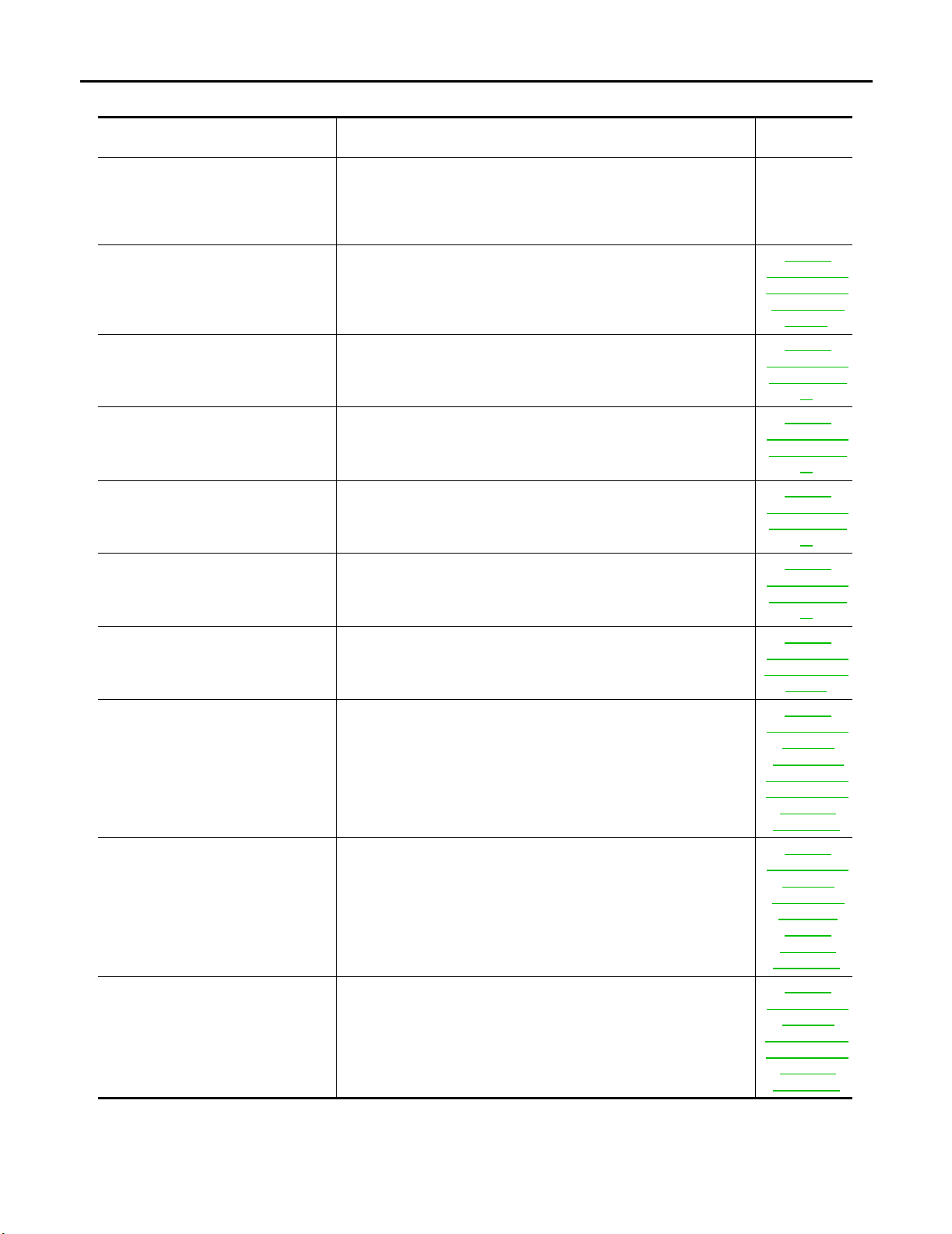
TROUBLE DIAGNOSES
Malfunction Code/Symptom Chart EES0 01V 9
Code/Symptom Malfunction part
15
16
17
18
21
22
23
24
31
32
33
34
35
36
37
38
41
42
43
44
45
46
47
48
52 Vehicle speed signal
Low tire pressure warning lamp does
not come on when ignition switch is
turned on.
Low tire pressure warning lamp stays
on when ignition switch is turned on.
Low tire pressure warning lamp
flashes when ignition switch is turned
on.
Front-left tire pressure drops to 193 kPa (2.0 kg/cm
Front-right tire pressure drops to 193 kPa (2.0 kg/cm
2
, 28 psi) or less
2
, 28 psi) or less
Rear-right tire pressure drops to 193 kPa (2.0 kg/cm2 , 28 psi) or less
2
Rear-left tire pressure drops to 193 kPa (2.0 kg/cm
, 28 psi) or less
Transmitter no data (front - left)
Transmitter no data (front - right)
Transmitter no data (rear - right)
Transmitter no data (rear - left)
Transmitter checksum error (front - left)
Transmitter checksum error (front - right)
Transmitter checksum error (rear - right)
Transmitter checksum error (rear - left)
Transmitter pressure data error (front - left)
Transmitter pressure data error (front - right)
Transmitter pressure data error (rear - right)
Transmitter pressure data error (rear - left)
Transmitter function code error (front - left)
Transmitter function code error (front - right)
Transmitter function code error (rear - right)
Transmitter function code error (rear - left)
Transmitter battery voltage low (front - left)
Transmitter battery voltage low (front - right)
Transmitter battery voltage low (rear - right)
Transmitter battery voltage low (rear - left)
● Fuse or combination meter
● BCM connector or circuit
● BCM
● Combination meter
● BCM connector or circuit
● BCM
● BCM harness connector or circuit
● BCM
● Transmitter 's mode o ff
● ID registration not completed yet
Reference
page
—
WT-24,
"Inspection 1:
Tran sm itter or
Control Unit
(BCM)"
WT-24,
"Inspection 2:
Transmitter -
1"
WT-25,
"Inspection 3:
Transmitter -
2"
WT-24,
"Inspection 2:
Transmitter -
1"
WT-24,
"Inspection 2:
Transmitter -
1"
WT-26,
"Inspection 4:
Vehicle Speed
Signal"
WT-27,
"Inspection 1:
Warning
Lamp Does
Not Come On
When Ignition
Switch Is
Turn ed On"
WT-28,
"Inspection 2:
Warning
Lamp Stays
On When
Ignition
Switch Is
Turn ed On"
WT-30,
"Inspection 3:
Warning
Lamp Flashes
When Ignition
Switch Is
Turn ed On"
Revision: September 2005 2006 Xterra
WT-22
Page 82
TROUBLE DIAGNOSES
Code/Symptom Malfunction part
Hazard warning lamp flashes when
ignition switch is turned on.
ID registration cannot be completed.
● BCM harness connector or circuit
● BCM
● Transmitter
● Remote keyless entry receiver harness connector or circuit
● Remote keyless entry receiver
● BCM harness connector or circuit
● BCM
Reference
page
WT-31,
"Inspection 4:
Hazard Warn-
ing Lamp
Flashes When
Ignition
Switch Is
Turned On"
WT-31,
"Inspection 5:
ID Registra-
tion Cannot
Be Com-
pleted"
A
B
C
D
WT
F
G
H
M
I
J
K
L
Revision: September 2005 2006 Xterra
WT-23
Page 83

TROUBLE DIAGNOSIS FOR SELF-DIAGNOSTIC ITEMS
TROUBLE DIAGNOSIS FOR SELF-DIAGNOSTIC ITEMS PFP:00000
Inspection 1: Transmitter or Control Unit (BCM) EES001VA
MALFUNCTION CODE NO. 21, 22, 23 OR 24
1. CHECK CONTROL UNIT
Drive for several minutes. Check all tire pressures with CONSULT-II “DATA MONITOR”.
Are all tire pressures displayed as 0 kPa (0 psi)?
YES >> GO TO 2.
NO >> GO TO 3.
2. CHECK REMOTE KEYLESS ENTRY RECEIVER CONNECTOR
Check remote keyless entry receiver connector for damage or loose connections.
OK or NG
OK >> Replace BCM, then GO TO 3. Refer to BCS-26, "Removal and Installation of BCM" .
NG >> Repair or replace remote keyless entry receiver connector.
3. ID REGISTRATION
Carry out ID registration of all transmitters. Refer to WT-12, "
Is there a tire that cannot register ID?
YES >> Replace transmitter of the tire, then GO TO 5. Refer to WT-32, "Transmitter (Pressure Sensor)" .
NO >> GO TO 4.
ID Registration Procedure" .
4. VEHICLE DRIVING
1. Drive at a speed of 40 km/h (25 MPH) or more for several minutes without stopping.
2. Check all tire pressures with CONSULT-II “DATA MONITOR” within 15 minutes after vehicle speed
becomes 17 km/h (11 MPH).
“DATA MONITOR” display tire pressure as normal without any warning lamp?
Does
YES >> Inspection End.
NO >> GO TO 5.
5. ID REGISTRATION AND VEHICLE DRIVING
1. Carry out ID registration of all transmitters. Refer to WT-12, "
2. Drive at a speed of 40 km/h (25 MPH) or more for 3 minutes, and then drive the vehicle at any speed for
10 minutes.
3. Check all tire pressures with CONSULT-II “DATA MONITOR” within 5 minutes.
Does
“DATA MONITOR” display tire pressure as normal without any warning lamp?
YES >> Inspection End.
NO >> GO TO the inspection applicable to DTC.
ID Registration Procedure" .
Inspection 2: Transmitter - 1 EES001VB
MALFUNCTION CODE NO. 31, 32, 33, 34, 41, 42, 43, 44, 45, 46, 47 OR 48
1. ID REGISTRATION (CORRECTION OF TRANSMITTER LOCATION)
1. Carry out ID registration of all transmitters. Refer to WT-12, "
2. Drive at a speed of 40 km/h (25 MPH) or more for 3 minutes, and then drive the vehicle at any speed for
10 minutes.
>> GO TO 2.
Revision: September 2005 2006 Xterra
WT-24
ID Registration Procedure" .
Page 84

TROUBLE DIAGNOSIS FOR SELF-DIAGNOSTIC ITEMS
2. REPLACE TRANSMITTER
1. Check low tire pressure warning lamp again for flashing, replace malfunctioning transmitter.
2. Carry out ID registration of all transmitters. Refer to WT-12, "
Can ID registration of all transmitters be completed?
YES >> GO TO 3.
NO >> GO TO Inspection 1. Refer to WT-24, "
Inspection 1: Transmitter or Control Unit (BCM)" .
ID Registration Procedure" .
3. VEHICLE DRIVING
1. Drive at a speed of 40 km/h (25 MPH) or more for 3 minutes, and then drive the vehicle at any speed for
10 minutes.
2. Check all tire pressures with CONSULT-II “DATA MONITOR” within 5 minutes.
Does
“DATA MONITOR ITEM” display tire pressure as normal without any warning lamp?
YES >> Inspection End.
NO >> Replace malfunctioning transmitter, and perform Step 3 again. Refer to WT-32, "
(Pressure Sensor)" .
Transmitter
Inspection 3: Transmitter - 2 EES001VC
MALFUNCTION CODE NO. 35, 36, 37 OR 38
1. CHECK ALL TIRE PRESSURES
Check all tire pressures. Refer to WT-34, "
Are there any tires with pressure of 64 psi or more?
YES >> Adjust tire pressure to specified value.
NO >> GO TO 2.
Tire" .
2. VEHICLE DRIVING
A
B
C
D
WT
F
G
H
I
1. Carry out ID registration of all transmitters. Refer to WT-12, "
2. Drive at a speed of 40 km/h (25 MPH) or more for several minutes without stopping.
3. Check all tire pressures with CONSULT-II “DATA MONITOR” within 15 minutes after vehicle speed
becomes 17 km/h (11 MPH).
Does
“DATA MONITOR” display 64 psi or more?
YES >> Replace transmitter. Refer to WT-32, "Transmitter (Pressure Sensor)" . GO TO 3.
NO >> GO TO 3.
ID Registration Procedure" .
3. ID REGISTRATION AND VEHICLE DRIVING
1. Carry out ID registration of all transmitters. Refer to WT-12, "
2. Drive at a speed of 40 km/h (25 MPH) or more for 3 minutes, and then drive the vehicle at any speed for
10 minutes.
3. Check all tire pressures with CONSULT-II “DATA MONITOR” within 5 minutes.
Does
“DATA MONITOR” display tire pressure as normal without any warning lamp?
YES >> Inspection End.
NO >> GO TO the inspection applicable to DTC.
ID Registration Procedure" .
J
K
L
M
Revision: September 2005 2006 Xterra
WT-25
Page 85
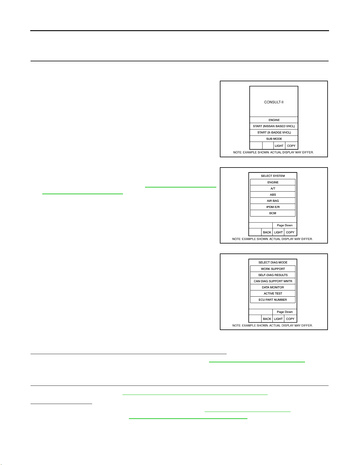
TROUBLE DIAGNOSIS FOR SELF-DIAGNOSTIC ITEMS
Inspection 4: Vehicle Speed Signal EES001VD
MALFUNCTION CODE NO. 52
1. SELF-DIAGNOSTIC RESULT CHECK
1. With the ignition switch OFF, connect CONSULT-II and CONSULT-II CONVERTER to the data link connector, then turn the ignition switch ON.
2. Select “START (NISSAN BASED VHCL)”.
BCIA0 029E
3. Select "BCM" on “SELECT SYSTEM” screen.
NOTE:
If the BCM is not indicated, refer to GI-41, "
Link Connector (DLC) Circuit" .
CONSULT-II Data
4. Select "BCM" on "SELECT TEST ITEM" screen, and select
"SELF-DIAG RESULTS".
5. Check display contents in self-diagnostic results.
Is "CAN COMM CIRCUIT" displayed in the self-diagnosis display items?
YES >> Malfunction in CAN communication system. GO TO LAN-21, "CAN COMMUNICATION" .
NO >> GO TO 2.
2. CHECK BCM
Perform BCM diagnosis. Refer to BCS-17, "
Inspection results OK?
OK >> Perform Vehicle Speed Sensor Inspection. Refer to AT-121, "Diagnostic Procedure" .
NG >> Replace BCM. Refer to BCS-26, "
CONSULT–II INSPECTION PROCEDURE" .
Removal and Installation of BCM" .
BCIA0 030E
BCIA0 031E
Revision: September 2005 2006 Xterra
WT-26
Page 86

TROUBLE DIAGNOSIS FOR SYMPTOMS
TROUBLE DIAGNOSIS FOR SYMPTOMS PFP:00007
Inspection 1: Warning Lamp Does Not Come On When Ignition Switch Is Turned
On
EES0 01V E
A
DIAGNOSTIC PROCEDURE
1. SELF-DIAGNOSTIC RESULT CHECK
1. With the ignition switch OFF, connect CONSULT-II and CONSULT-II CONVERTER to the data link connector, then turn the ignition switch ON.
2. Select “START (NISSAN BASED VHCL)”.
BCIA0 029E
3. Select "BCM" on “SELECT SYSTEM” screen.
NOTE:
If the BCM is not indicated, refer to GI-41, "
Link Connector (DLC) Circuit" .
CONSULT-II Data
B
C
D
WT
F
G
H
I
4. Select "BCM" on "SELECT TEST ITEM" screen, and select
"SELF-DIAG RESULTS".
5. Check display contents in self-diagnostic results.
Is "CAN COMM CIRCUIT" displayed in the self-diagnosis display items?
YES >> Malfunction in CAN communication system. Go To LAN-21, "CAN COMMUNICATION" .
NO >> GO TO 2.
2. CHECK COMBINATION METER
Check combination meter operation. Refer to DI-7, "
Inspection results OK?
OK >> GO TO 3.
NG >> Replace combination meter. Refer to DI-7, "
Combination Meter"
Combination Meter" .
J
BCIA0 030E
K
L
M
BCIA0 031E
Revision: September 2005 2006 Xterra
WT-27
Page 87
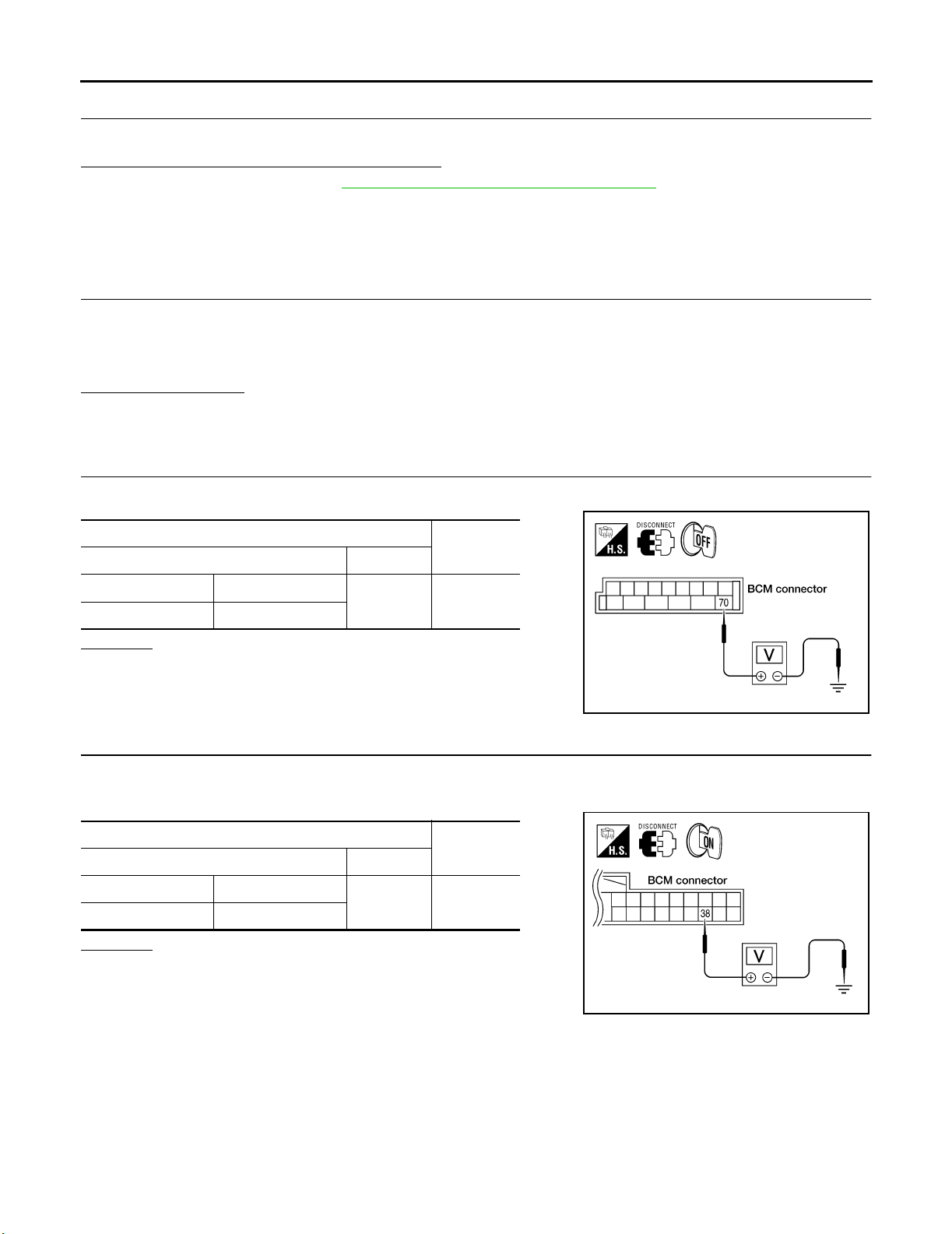
TROUBLE DIAGNOSIS FOR SYMPTOMS
3. CHECK LOW TIRE PRESSURE WARNING LAMP
Disconnect BCM harness connector.
Does the low tire pressure warning lamp activate?
YES >> Replace BCM. Refer to BCS-26, "Removal and Installation of BCM" .
NO >> Check combination meter and repair or replace.
Inspection 2: Warning Lamp Stays On When Ignition Switch Is Turned On EES001VF
DIAGNOSTIC PROCEDURE
1. CHECK CONNECTOR
1. Turn ignition switch OFF.
2. Disconnect BCM harness connectors M18 and M20.
3. Check terminals for damage or loose connections.
Inspection results OK?
OK >> GO TO 2.
NG >> Repair or replace damaged parts.
2. CHECK POWER SUPPLY CIRCUIT (BAT)
Check voltage between BCM harness connector M20 terminal 70 and ground.
1.
Term i nal s
(+) (–)
Vol t age
(Approx.)
Connector Terminal
Ground
M20 70
OK or NG
OK >> GO TO 3.
NG >> Check BCM power supply circuit for open or short.
Battery
voltage
3. CHECK POWER SUPPLY CIRCUIT (IGN)
1. Turn ignition switch ON.
2. Check voltage between BCM harness connector M18 terminal 38 and ground.
Term i nal s
(+) (–)
Connector Terminal
Ground
M18 38
OK or NG
OK >> GO TO 4.
NG >> Check BCM power supply circuit for open or short.
Vol t age
(Approx.)
Battery
voltage
LEIA00 98E
WEIA0038E
Revision: September 2005 2006 Xterra
WT-28
Page 88
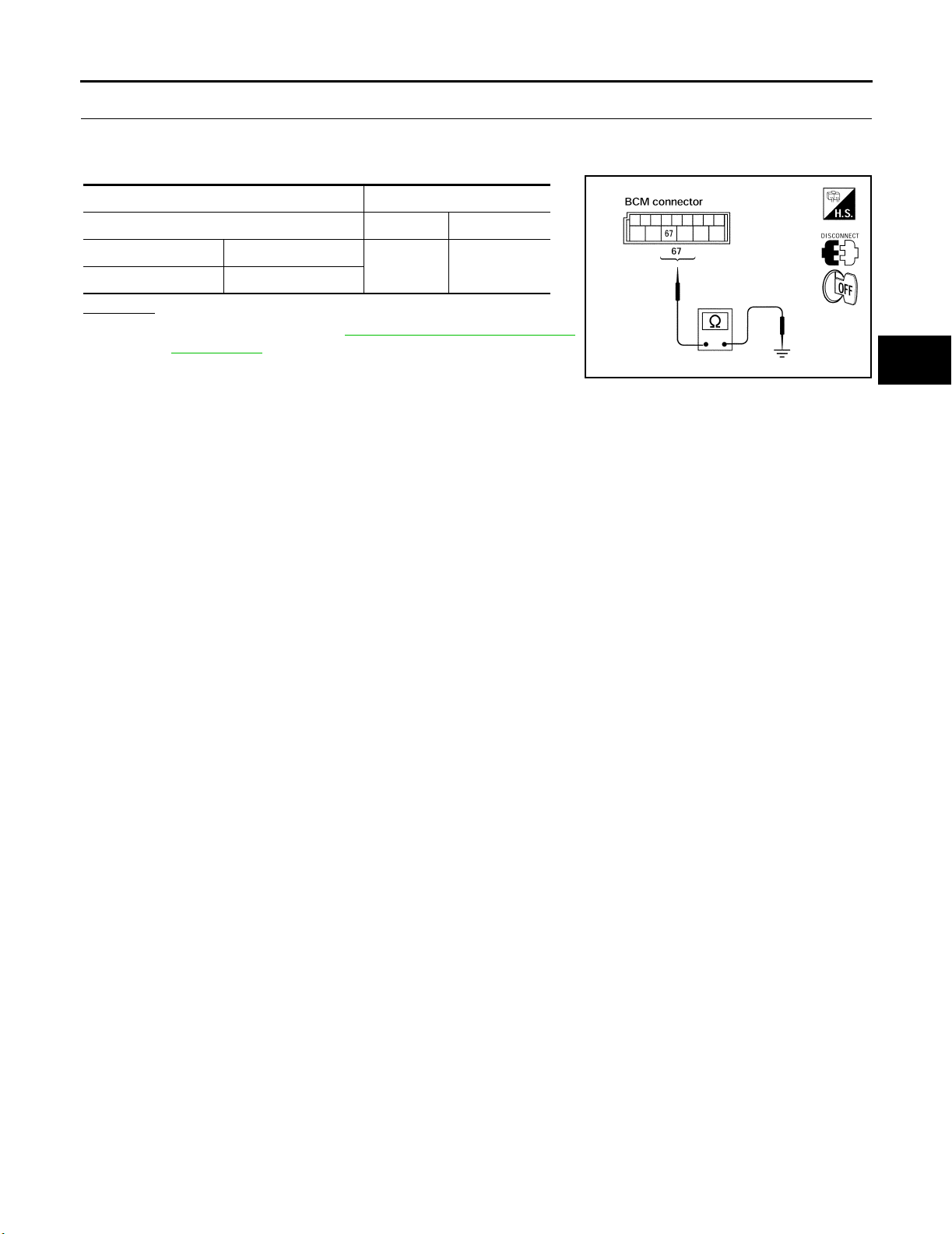
TROUBLE DIAGNOSIS FOR SYMPTOMS
4. CHECK GROUND CIRCUIT
1. Turn ignition switch OFF.
2. Check continuity between BCM harness connector M20 terminal 67 and ground.
Term i nal s Co ntin uity
(+) (–)
Connector Terminal
Ground Yes
M20 67
OK or NG
OK >> Replace BCM. Refer to BCS-26, "Removal and Installa-
tion of BCM" .
NG >> Repair BCM ground circuit.
LIIA10 40E
A
B
C
D
WT
F
G
H
M
I
J
K
L
Revision: September 2005 2006 Xterra
WT-29
Page 89
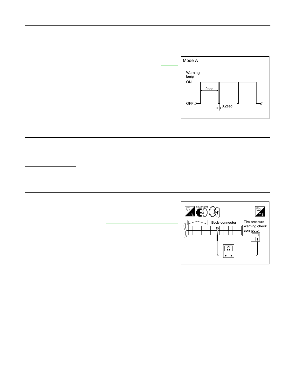
TROUBLE DIAGNOSIS FOR SYMPTOMS
Inspection 3: Warning Lamp Flashes When Ignition Switch Is Turned On EES001VG
NOTE:
If warning lamp flashes as shown, the system is normal.
Flash Mode A
● This mode shows transmitter status is OFF-mode.
Carry out transmitter wake up operation. Refer to WT-16,
"Transmitter Wake Up Operation" .
SEIA 0347E
DIAGNOSTIC PROCEDURE
1. CHECK CONNECTOR
1. Turn ignition switch OFF.
2. Disconnect BCM harness connectors M18 and M20.
3. Check terminals for damage or loose connections.
Inspection results OK?
OK >> GO TO 2.
NG >> Repair or replace damaged parts.
2. CHECK TIRE PRESSURE WARNING CHECK CONNECTOR CIRCUIT
Check continuity between BCM harness connector M18 terminal 15 and check connector M123 terminal 1.
Continuity should exist.
OK or NG
OK >> Replace BCM. Refer to BCS-26, "Removal and Installa-
tion of BCM" .
NG >> Repair or replace harness connector.
WEIA0127E
Revision: September 2005 2006 Xterra
WT-30
Page 90

TROUBLE DIAGNOSIS FOR SYMPTOMS
Inspection 4: Hazard Warning Lamp Flashes When Ignition Switch Is Turned On
EES001VH
DIAGNOSTIC PROCEDURE
1. CHECK GROUND CIRCUIT
1. Turn ignition switch OFF.
2. Disconnect BCM harness connector M20.
3. Check continuity between BCM harness connector M20 terminal 67 and ground.
Term i nal s
(+) (–)
Connector Terminal
Ground Yes
M20 67
OK or NG
OK >> Replace BCM. Refer to BCS-26, "Removal and Installa-
tion of BCM" .
NG >> Repair BCM ground circuit.
Continuity
LIIA10 40E
Inspection 5: ID Registration Cannot Be Completed EES001 VI
DIAGNOSTIC PROCEDURE
1. ID REGISTRATION (ALL)
Carry out ID registration of all transmitters. Refer to WT-12, "
Can ID registration of all transmitters be completed?
YES >> Inspection End.
NO >> GO TO WT-24, "
Inspection 1: Transmitter or Control Unit (BCM)" .
ID Registration Procedure" .
A
B
C
D
WT
F
G
H
I
M
J
K
L
Revision: September 2005 2006 Xterra
WT-31
Page 91
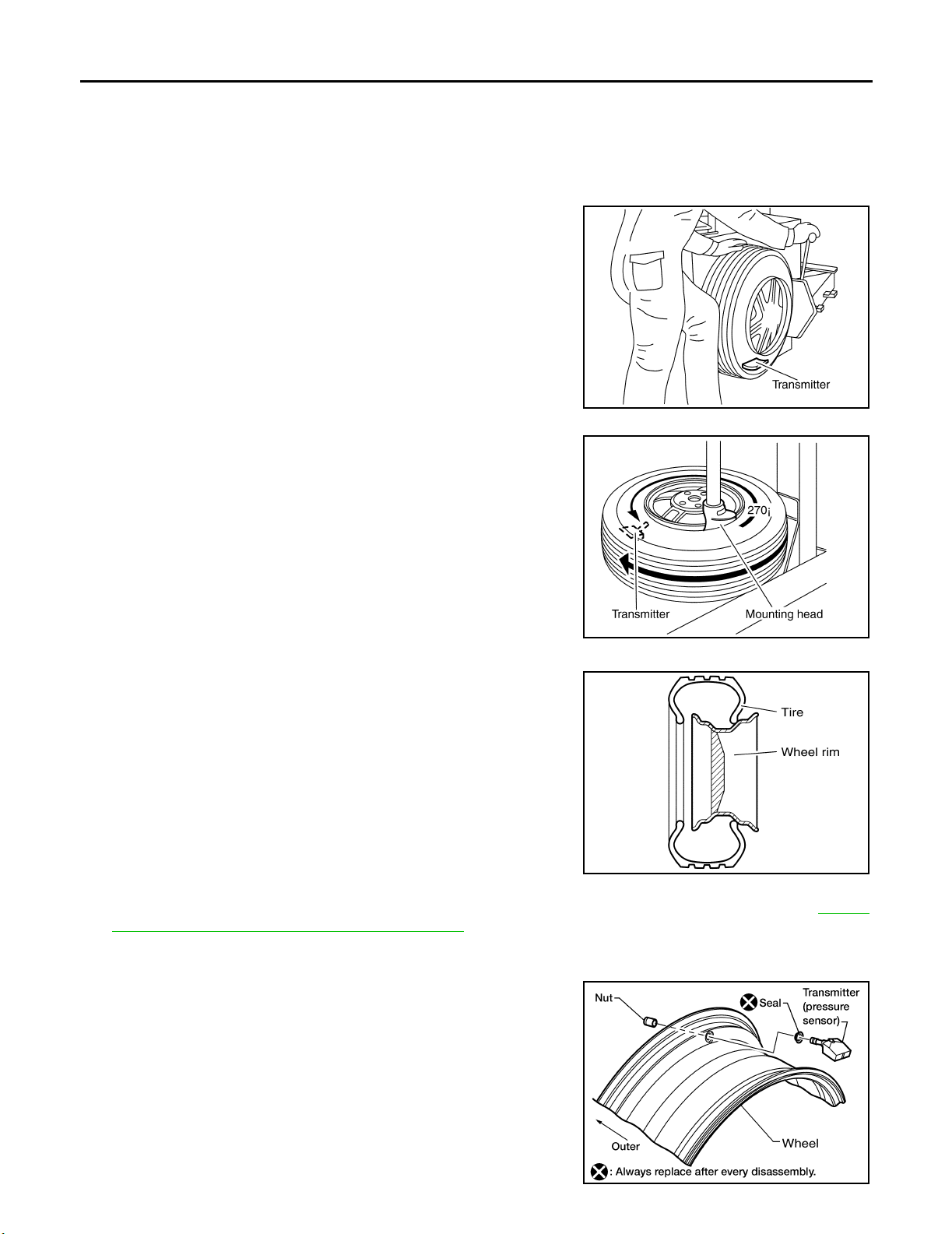
REMOVAL AND INSTALLATION
REMOVAL AND INSTALLATION PFP:00000
Transmitter (Pressure Senso r) EES0 01S 3
REMOVAL
1. Remove wheel and tire using power tool.
2. Deflate tire. Unscrew transmitter retaining nut and allow transmitter to fall into tire.
3. Gently bounce tire so that transmitter falls to bottom of tire.
Place wheel and tire assembly on tire changing machine and
break both tire beads. Ensure that the transmitter remains at the
bottom of the tire while breaking the bead.
SEIA 0047E
4. Turn tire so that valve hole is at bottom, and gently bounce the
tire to ensure transmitter is near valve hole. Carefully lift tire onto
turntable and position valve hole (and transmitter) 270 degrees
from mounting/dismounting head.
5. Lubricate tire well, and remove top side of tire. Reach inside the
tire and remove the transmitter.
6. Remove the second side of the tire as normal.
SEIA 0048E
INSTALLATION
1. Place first side of tire onto rim.
SEIA 0049E
2. Apply suitable silicone lubricant to new transmitter seal then install seal on transmitter. Refer to MA-11,
"RECOMMENDED FLUIDS AND LUBRICANTS" .
NOTE:
Always replace the seal after every disassembly.
3. Mount transmitter on rim and tighten nut to specification.
NOTE:
Make sure no burrs exist in the valve stem hole of the wheel.
Transmitter nut : 5.5 N·m (0.56 kg-m, 49 in-lb)
WEIA0137E
Revision: September 2005 2006 Xterra
WT-32
Page 92
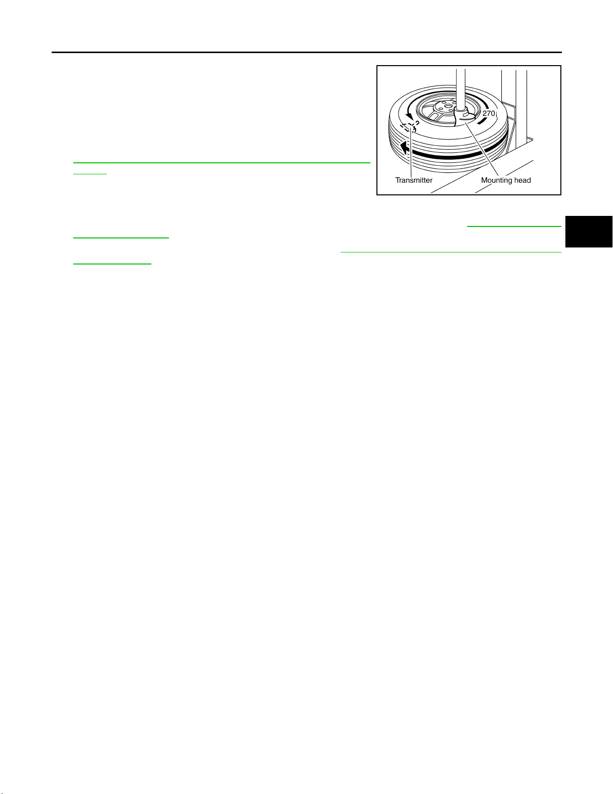
REMOVAL AND INSTALLATION
4. Place wheel on turntable of tire machine. Ensure that transmitter
is 270 degrees from mounting/dismounting head.
NOTE:
Do not touch transmitter with mounting head.
5. Lubricate tire well, and install second side of tire as normal.
Ensure that tire does not rotate relative to rim.
6. Inflate tire and balance the wheel and tire assembly. Refer to
WT-6, "
WHEEL BALANCE INSTALLATION AND ADJUST-
MENT" .
7. Install wheel and tire assembly in appropriate wheel position on
vehicle.
NOTE:
If replacing transmitter, transmitter wake up operation must be performed. Refer to WT-16, "
Wake Up Operation" .
8. Adjust neutral position of steering angle sensor. Refer to BRC-57, "
Adjustment of Steering Angle Sensor
Neutral Position" .
SEIA 0048E
Transmitter
A
B
C
D
WT
F
G
H
M
I
J
K
L
Revision: September 2005 2006 Xterra
WT-33
Page 93
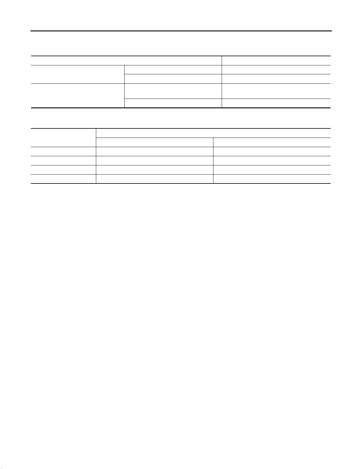
SERVICE DATA AND SPECIFICATIONS (SDS)
SERVICE DATA AND SPECIFICATIONS (SDS) PFP:00030
Road Wheel EES0 01S 4
Wheel type Aluminum
Maximum radial runout limit
Maximum residual imbalance
Lateral mm (in) 0.3 (0.012) or less
Radial mm (in) 0.3 (0.012) or less
Dynamic
(at rim flange)
Static (at r im flange) Les s than 10 g (0.35 oz)
Less than 5 g (0.18 oz) (per side)
Tire EES0 01S 5
Unit: kPa (kg/cm2 , psi)
Tire size
Full size spare tire — 240 (2.4, 35)
P265/70R16 240 (2.4, 35) —
P265/75R16 240 (2.4, 35) —
P265/65R17 240 (2.4, 35) —
Conventional tire Spare tire
Air pressure
Revision: September 2005 2006 Xterra
WT-34
Page 94

H RESTRAINTS
A
B
SECTION SRS
SUPPLEMENTAL RESTRAINT SYSTEM (SRS)
CONTENTS
PRECAUTIONS .......................................................... 3
Precautions for Supplemental Restraint System
(SRS) “AIR BAG” and “SEAT BELT PRE-TEN-
SIONER” .................................................................. 3
Precautions for SRS “AIR BAG” and “SEAT BELT
PRE-TENSIONER” Service ..................................... 3
Occupant Classification System Precaution ............ 3
PREPARATION ........................................................... 4
Special Service Tools ............................................... 4
SUPPLEMENTAL RESTRAINT SYSTEM (SRS) ....... 5
SRS Configuration ................................................... 5
Front Seat Belt Pre-tensioner with Load Limiter ...... 6
Front Side Air Bag .................................................... 6
Side Curtain Air Bag ................................................. 6
Occupant Classification System (OCS) ................... 6
Direct-connect SRS Component Connectors ........... 7
TROUBLE DIAGNOSIS .............................................. 8
Trouble Diagnosis Introduction ................................. 8
DIAGNOSIS FUNCTION ....................................... 8
HOW TO PERFORM TROUBLE DIAGNOSES
FOR QUICK AND ACCURATE REPAIR ............... 8
WORK FLOW ........................................................ 9
SRS Components Parts Location ........................... 10
Schematic ............................................................... 11
Wiring Diagram — SRS — ..................................... 12
CONSULT-II Function (AIR BAG) ........................... 18
CONSULT-II Function ............................................ 18
HOW TO CHANGE SELF-DIAGNOSIS MODE
WITH CONSULT-II .............................................. 18
HOW TO ERASE SELF-DIAGNOSIS RESULTS ... 19
Self-Diagnosis Function (Without CONSULT-II) ..... 19
HOW TO CHANGE SELF-DIAGNOSIS MODE ... 20
HOW TO ERASE SELF-DIAGNOSIS RESULTS ... 20
SRS Operation Check ............................................ 20
DIAGNOSTIC PROCEDURE 1 ........................... 20
Trouble Diagnosis With CONSULT-II ..................... 22
DIAGNOSTIC PROCEDURE 2 ........................... 22
DIAGNOSTIC PROCEDURE 3 ........................... 27
DIAGNOSTIC PROCEDURE 4 (CONTINUED
FROM DIAGNOSTIC PROCEDURE 2) .............. 29
DIAGNOSTIC PROCEDURE 5 ........................... 29
Trou ble Diagnosis Without CONSULT-II ................. 35
DIAGNOSTIC PROCEDURE 6 ........................... 35
WARNING LAMP FLASH CODE CHART ........... 36
Trou ble Diagnosis: “AIR BAG” Warning Lamp Does
Not Turn Off ............................................................ 40
DIAGNOSTIC PROCEDURE 6 ........................... 40
Trou ble Diagnosis: “AIR BAG” Warning Lamp Does
Not Turn On ............................................................ 41
DIAGNOSTIC PROCEDURE 7 ........................... 41
DRIVER AIR BAG MODULE .................................... 42
Removal and Installation ........................................ 42
REMOVAL ........................................................... 42
INSTALLATION ................................................... 43
SPIRAL CABLE ........................................................ 44
Removal and Installation ........................................ 44
REMOVAL ........................................................... 44
INSTALLATION ................................................... 45
FRONT PASSENGER AIR BAG MODULE .............. 46
Removal and Installation ........................................ 46
REMOVAL ........................................................... 46
INSTALLATION ................................................... 47
WIRING HARNESS MODIFICATION .................. 48
SIDE CURTAIN AIR BAG MODULE ........................ 50
Removal and Installation ........................................ 50
REMOVAL ........................................................... 50
INSTALLATION ................................................... 50
CRASH ZONE SENSOR ........................................... 52
Removal and Installation ........................................ 52
REMOVAL ........................................................... 52
INSTALLATION ................................................... 52
SIDE AIR BAG (SATELLITE) SENSOR ................... 53
Removal and Installation ........................................ 53
REMOVAL ........................................................... 53
INSTALLATION ................................................... 53
FRONT SEAT BELT PRE-TENSIONER ................... 54
Removal and Installation ........................................ 54
C
D
E
F
G
SRS
I
J
K
L
M
Revision: September 2005 2006 Xterra
SRS-1
Page 95

DIAGNOSIS SENSOR UNIT ..................................... 55
Removal and Installation ........................................ 55
REMOVAL ........................................................... 55
INSTALLATION .................................................... 55
ECU DISCRIMINATED NUMBER ....................... 55
OCCUPANT CLASSIFICATION SYSTEM CON-
TROL UNIT ................................................................ 56
Removal and Installation ........................................ 56
COLLISION DIAGNOSIS .......................................... 57
For Frontal Collision ................................................ 57
SRS INSPECTION (FOR FRONTAL COLLI-
SION) ...................................................................57
For Side and Rollover Collision ...............................58
WHEN SRS IS ACTIVATED IN THE SIDE OR
ROLLOVER COLLISION .....................................58
WHEN SRS IS NOT ACTIVATED IN THE SIDE
OR ROLLOVER COLLISION ...............................58
SRS INSPECTION (FOR SIDE AND ROLLOVER
COLLISION) .........................................................59
Revision: September 2005 2006 Xterra
SRS-2
Page 96

PRECAUTIONS
PRECAUTIONS PFP:00001
Precautions for Supplemental Restraint System (SRS) “AIR BAG” and “SEAT
BELT PRE-TENSIONER”
EHS001DP
A
The Supplemental Restraint System such as “AIR BAG” and “SEAT BELT PRE-TENSIONER”, used along
with a front seat belt, helps to reduce the risk or severity of injury to the driver and front passenger for certain
types of collision. This system includes seat belt switch inputs and dual stage front air bag modules. The SRS
system uses the seat belt switches to determine the front air bag deployment, and may only deploy one front
air bag, depending on the severity of a collision and whether the front occupants are belted or unbelted.
Information necessary to service the system safely is included in the SRS and SB section of this Service Manual.
WARNING:
● To avoid ren dering the SRS inoperativ e, w h ich cou ld increa se the risk o f perso nal injury or death
in the event of a collision which would result in air bag inflation, all maintenance must be performed by an authorized NISSAN/INFINITI dealer.
● Improper maintenance, including incorrect removal and installation of the SRS, can lead to per-
sonal injury caused by unintentional activation of the system. For removal of Spiral Cable and Air
Bag Module, see the SRS section.
● Do not use electrical test equipment on any circuit related to the SRS unless instructed to in this
Service Manual. SRS wiring harnesses can be identified by yellow and/or orange harnesses or
harness connectors.
Precautions for SRS “AIR BAG” and “SEAT BELT PRE-TENSIONER” Service
EHS001DQ
● Do not use electrical test equipment to check SRS circuits unless instructed to in this Service Manual.
● Before servicing the SRS, turn ignition switch OFF, disconnect both battery cables and wait at least 3 min-
utes.
For approximately 3 minutes after the cables are removed, it is still possible for the air bag and seat belt
pre-tensioner to deploy. Therefore, do not work on any SRS connectors or wires until at least 3 minutes
have passed.
● The air bag diagnosis sensor unit must always be installed with the arrow mark “⇐” pointing toward the
front of the vehicle for proper operation. Also check the air bag diagnosis sensor unit for cracks, deformities or rust before installation and replace as required.
● The spiral cable must be aligned with the neutral position since its rotations are limited. Do not attempt to
turn steering wheel or column after removal of steering gear.
● Handle air bag module carefully. Always place driver and front passenger air bag modules with the pad
side facing upward and seat mounted front side air bag module standing with the stud bolt side facing
down.
● Conduct self-diagnosis to check entire SRS for proper function after replacing any components.
● After air bag inflates, the front instrument panel assembly should be replaced if damaged.
Occupant Classification System Precaution EHS001G2
B
C
D
E
F
G
SRS
I
J
K
L
M
Replace control unit and passenger front seat cushion as an assembly.
Revision: September 2005 2006 Xterra
SRS-3
Page 97
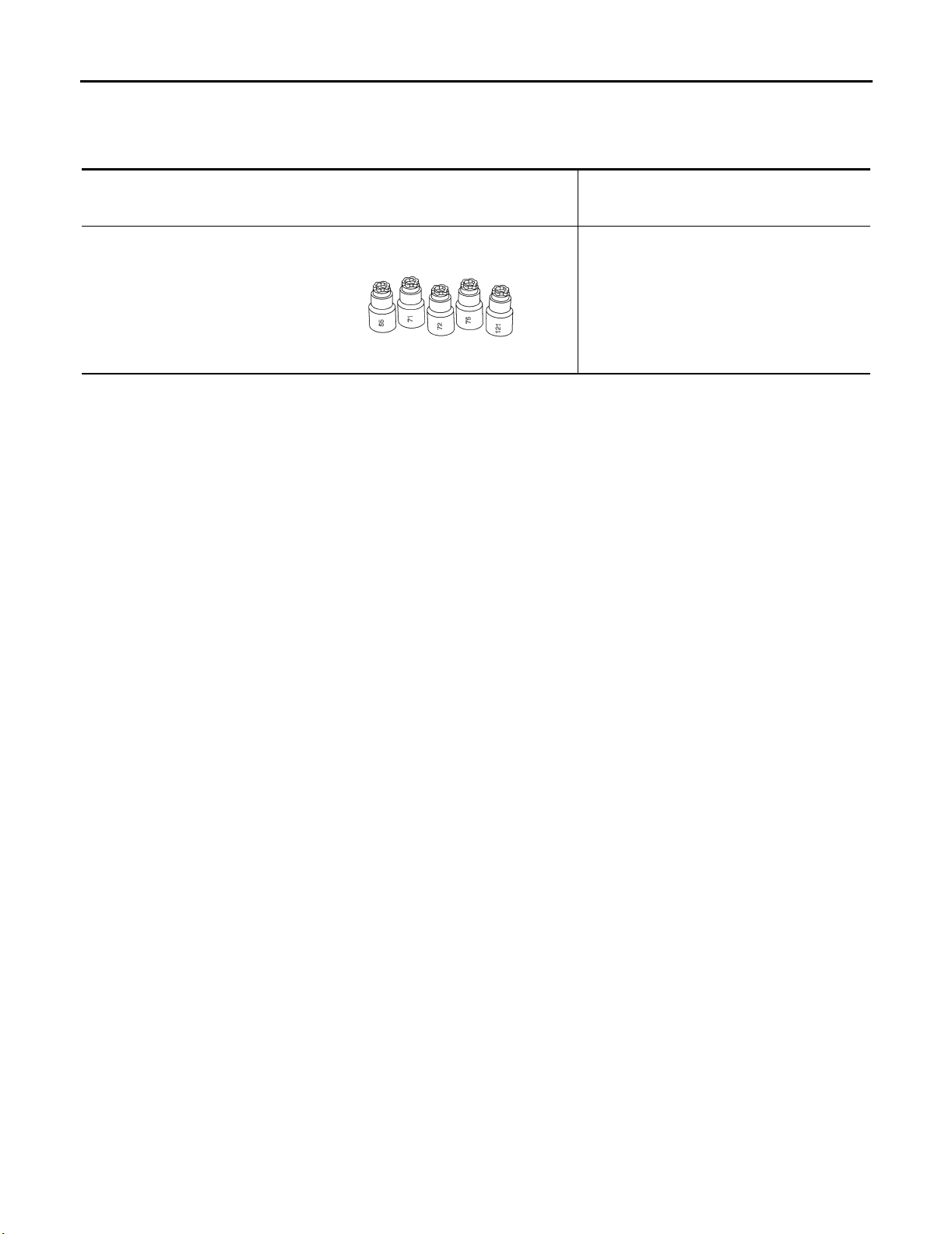
PREPARATION
PREPARATION PFP:00002
Special Service Tools EHS001DT
The actual shapes of Kent-Moore tools may differ from those of special service tools illustrated here.
Tool number
(Kent-Moore No.)
Tool name
—
(J-42057-UPD)
Air bag key set
Part of kit (J-42057)
LRS210
Description
Removing and installing air bag lock
Revision: September 2005 2006 Xterra
SRS-4
Page 98
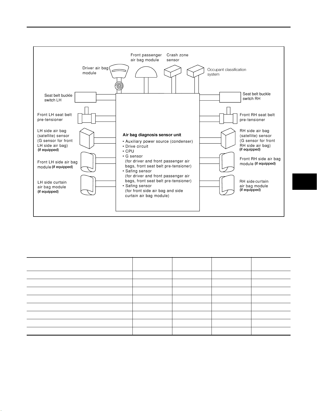
SUPPLEMENTAL RESTRAINT SYSTEM (SRS)
SUPPLEMENTAL RESTRAINT SYSTEM (SRS) PFP:28556
SRS Configuration EHS001G3
A
B
C
D
E
F
G
WHIA0224E
The air bag deploys if the air bag diagnosis sensor unit is activated while the ignition switch is in the ON or
START position. The collision modes for which supplemental restraint systems are activated are different
among the SRS systems. For example, the driver air bag module, front passenger air bag module and front
seat belt pre-tensioners are activated in a frontal collision but not in a side collision.
SRS configurations for some collision modes are as follows:
SRS configuration Frontal collision Left side collision
Driver air bag module x — — —
Front passenger air bag module x — — —
Front LH seat belt pre-tensioner x — — x
Front RH seat belt pre-tensioner x — — x
Front LH side air bag module — x — —
Front RH side air bag module — — x —
LH side curtain air bag module — x — x
RH side curtain air bag module — — x x
Right side colli-
sion
Rollover
SRS
I
J
K
L
M
Revision: September 2005 2006 Xterra
SRS-5
Page 99
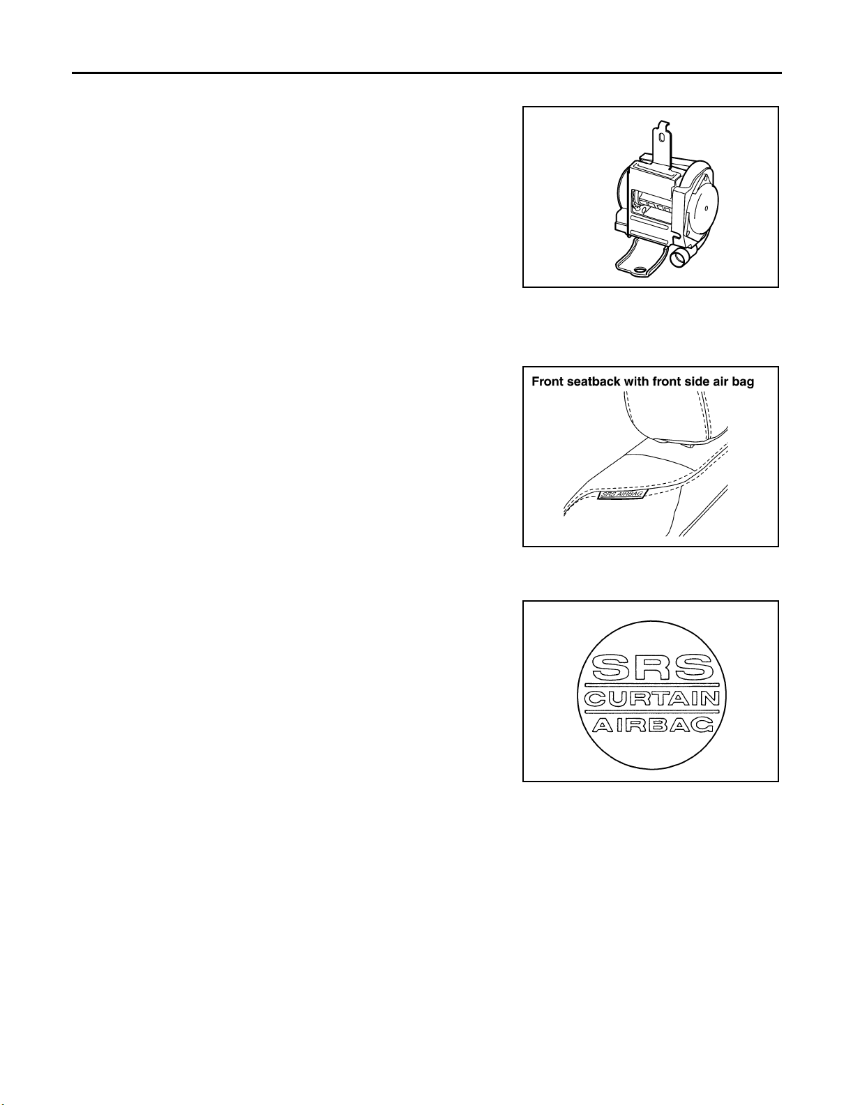
SUPPLEMENTAL RESTRAINT SYSTEM (SRS)
Front Seat Belt Pre-tensioner with Load Limiter EHS001G4
The seat belt pre-tensioner system with load limiter is installed for
both the driver's seat and the front passenger's seat. It operates
simultaneously with the SRS air bag system in the event of a frontal
collision with an impact exceeding a specified level.
When the frontal collision with an impact exceeding a specified level
occurs, seat belt slack resulting from clothing or other factors is
immediately taken up by the pre-tensioner. Vehicle passengers are
securely restrained.
When passengers in a vehicle are thrown forward in a collision and
the restraining force of the seat belt exceeds a specified level, the
load limiter permits the specified extension of the seat belt by the
twisting of the ELR shaft, and a relaxation of the chest-area seat belt
web tension while maintaining force.
WHIA0225E
Front Side Air Bag EHS001G5
Front side air bag modules are built into the front seatback assemblies.
Vehicles with side air bags are equipped with labels as shown.
WHIA0008E
Side Curtain Air Bag EHS001G6
Side curtain air bag modules are located above the vehicle headlining.
Vehicles with side curtain air bags are equipped with labels as
shown.
WHIA0041E
Occupant Classification System (OCS) EHS001SE
The occupant classification system (OCS) identifies different size occupants, out of position occupants, and
detects if child seat is present in the front passenger seat. The OCS receives inputs from the occupant classification sensor (located inside the passenger seat cushion assembly) and belt tension sensor (part of the passenger front seat belt assembly and located at the belt anchor location). Depending on classification of the
passenger, the OCS sends a signal to the air bag diagnosis sensor unit. The air bag diagnosis sensor unit
uses this signal and the seat belt buckle switch RH signal to determine deployment or non deployment of the
passenger front air bag in the event of a collision. Depending on the signals received, the air bag diagnosis
sensor unit can disable the passenger front air bag completely.
NOTE:
In case of customer concern, CONSULT-II can be used to confirm the passenger air bag status (readiness).
Revision: September 2005 2006 Xterra
SRS-6
Page 100
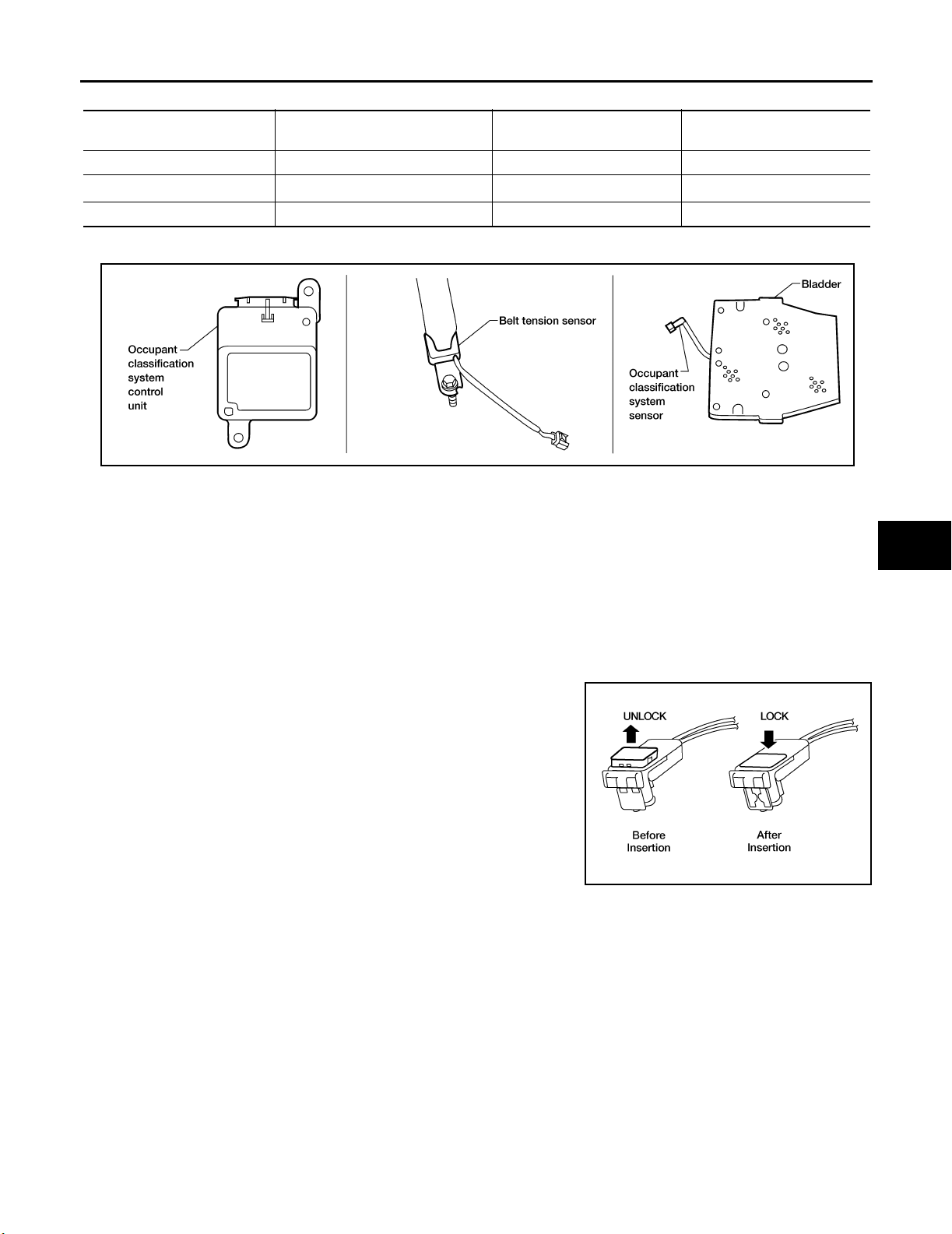
SUPPLEMENTAL RESTRAINT SYSTEM (SRS)
Passenger Air Bag Status Conditions
Front Passenger Seat
(Condition)
Seat occupied OFF Active (enabled) ON
Seat occupied
Seat empty OFF Deactivated (disabled) OFF
NOTE:
Passenger does not meet Occupant Classification System specifications for passenger air bag activation.
NOTE
PA SS A IR BA G OF F In di ca to r
(Status)
ON Deactivated (disabled) OFF
Passenger Air Bag Status
(Readiness)
CONSULT-II Display
A
B
C
D
E
F
WHIA0195E
Direct-connect SRS Component Connectors EHS001G8
The following SRS components use direct-connect style harness connectors.
● Driver air bag module
● Front passenger air bag module
● LH side curtain air bag module
● RH side curtain air bag module
● Front LH seat belt pre-tensioner
● Front RH seat belt pre-tensioner
Always pull up to release black locking tab prior to removing connector from SRS component.
Always push down to lock black locking tab after installing connector
to SRS component. When locked, the black locking tab is level with
the connector housing.
WHIA0103E
G
SRS
I
J
K
L
M
Revision: September 2005 2006 Xterra
SRS-7
 Loading...