

Page 1

nissan :: Nissan-Datsun Truck Xterra SE 2WD V6-
3.3L (VG33E) (2002)
Page 2
> Relays and Modules > Relays and Modules - Accessories and Optional Equipment > Antitheft Relay > Component Information > Locations
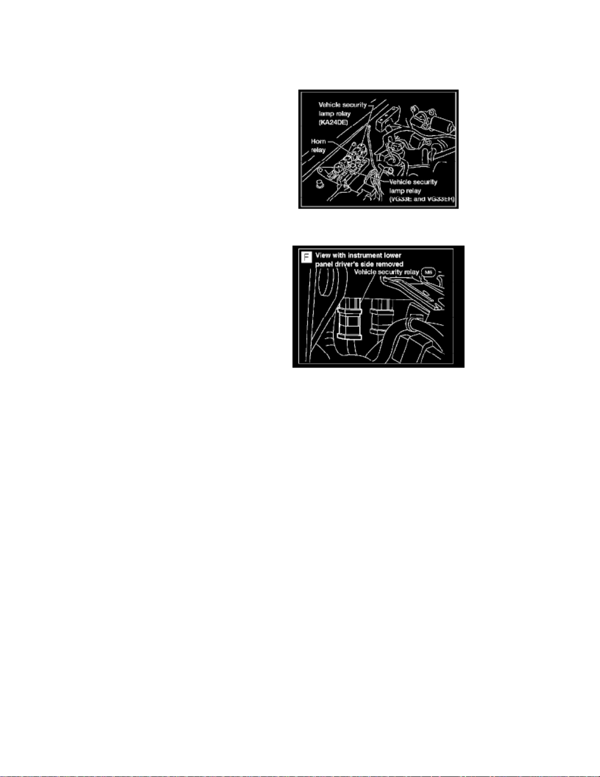
Antitheft Relay: Locations
Vehicle Security Lamp Relay/Horn Relay
Component View F
Page 3

Page 4
> Relays and Modules > Relays and Modules - Accessories and Optional Equipment > Antitheft Relay > Component Information > Locations > Page 7
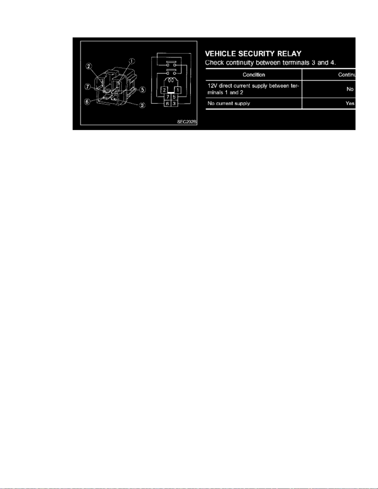
Vehicle Security Relay
Page 5

Page 6
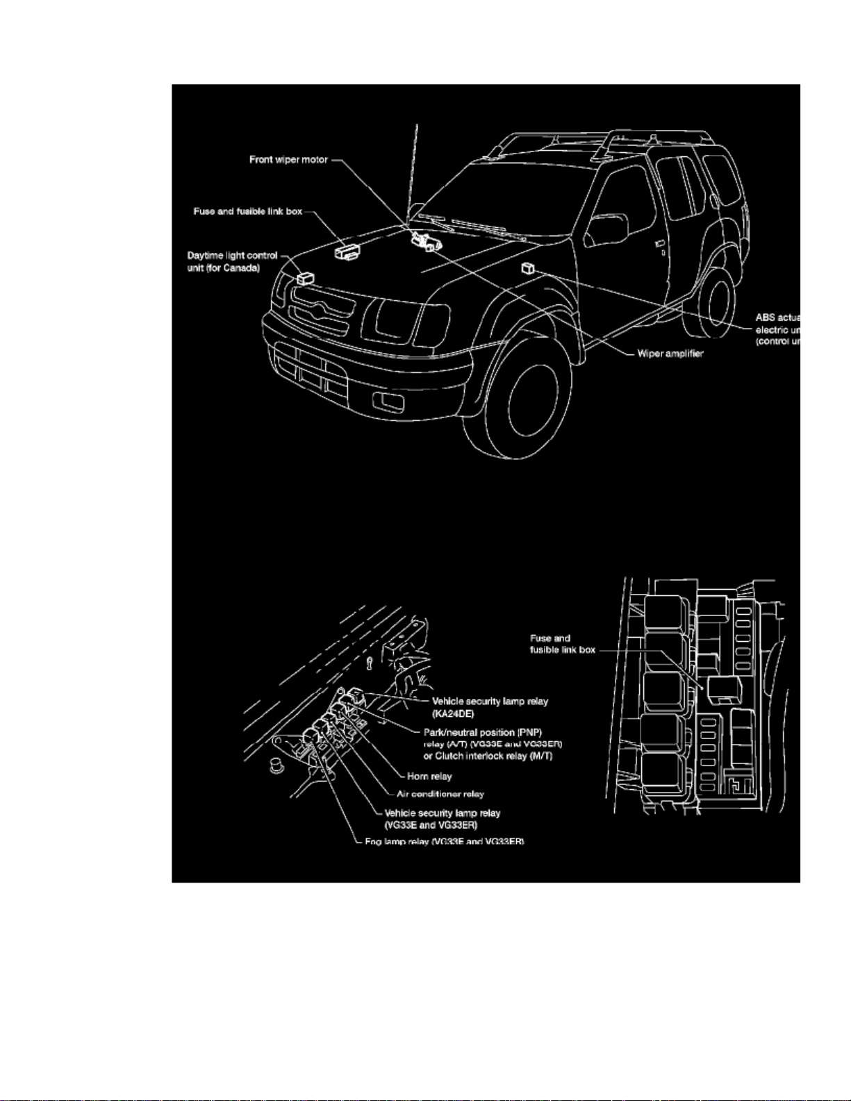
> Relays and Modules > Relays and Modules - Brakes and Traction Control > Electronic Brake Control Module > Component Information > Locations
Engine Compartment
Page 7

Page 8
> Relays and Modules > Relays and Modules - Brakes and Traction Control > Electronic Brake Control Module > Component Information > Locations > Page 12
Page 9

Page 10
> Relays and Modules > Relays and Modules - Brakes and Traction Control > Electronic Brake Control Module > Component Information > Locations > Page 13
Electronic Brake Control Module: Description and Operation
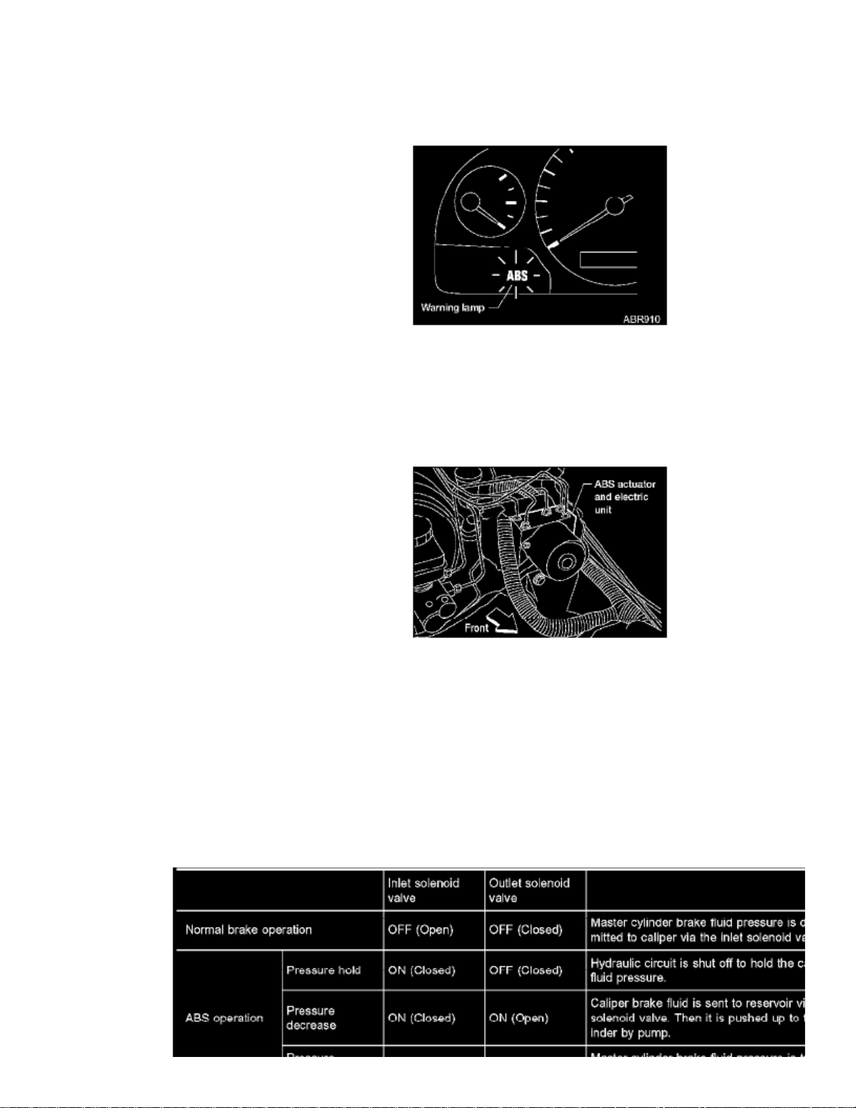
CONTROL UNIT (BUILT-IN ABS ACTUATOR AND ELECTRIC UNIT)
The control unit computes the wheel rotating speed by the signal current sent from the sensor. Then it supplies a DC current to the actuator solenoidvalve. It also controls ON-OFF operation of the valve relay and motor relay. If any electrical malfunction should be detected in the system, the controlunit causes the warning lamp to light up. In this condition, the ABS will be deactivated by the control unit, and the vehicle's brake system reverts tonormal operation. For control unit layout, refer to "ABS ACTUATOR AND ELECTRIC UNIT".
ABS ACTUATOR AND ELECTRIC UNIT
The ABS actuator and electric unit contains:^
An electric motor and pump
^ Two relays
^
Six solenoid valves. An inlet and outlet each for -
LH front
- RH front
- Rear
^ ABS control unit
This component controls the hydraulic circuit and increases, holds or decreases hydraulic pressure to all or individual wheels. The ABS actuator andelectric unit is serviced as an assembly.
Page 11

ABS Actuator Operation
Page 12

> Relays and Modules > Relays and Modules - Brakes and Traction Control > Electronic Brake Control Module > Component Information > Locations > Page 14
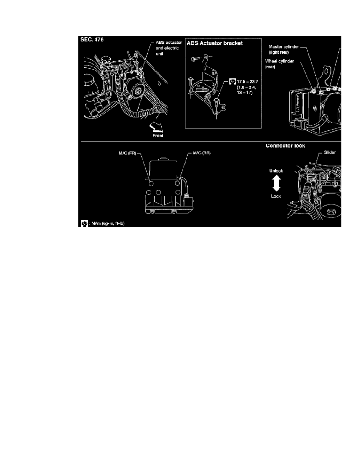
Electronic Brake Control Module: Service and Repair
REMOVAL
1. Disconnect battery cable.2. Drain brake fluid.3. Remove mounting bracket fixing bolts and nuts.4. Disconnect connector, brake pipes and remove fixing nuts and actuator ground cable.
INSTALLATION
After installation, refill brake fluid. Then bleed air. CAUTION:
1. Tighten actuator ground cable.
Place ground cable at a notch of mounting bracket.
2. Connect brake pipes temporarily.3. Tighten fixing bolts and nuts.4. Tighten brake pipes.5. Connect connector and battery cable.
Page 13

Page 14
> Relays and Modules > Relays and Modules - Cruise Control > Cruise Control Module > Component Information > Technical Service Bulletins > All Technical Service Bulletins for Cruise Control Module: > 03-037 > Apr > 03
> Cruise Control - Engine Surging/No A/T Upshift
Cruise Control Module: All Technical Service BulletinsCruise Control - Engine Surging/No A/T Upshift
Classification:EC02-032
Reference:NTB03-037
Date:April 15, 2003
2001-2002 FRONTIER AND XTERRA VG33;"SURGE" OR NO A/T UPSHIFT WITH ASCD "ON"
APPLIED VEHICLES:2001-2002 Frontier (D22) - All with A/T2001-2002 Xterra (WD22) - All with A/T
APPLIED ENGINE:V16 (VG33E or VG33ER) only
APPLIED TRANSMISSION:Automatic Transmission only
IF YOU CONFIRM:
When using the Automatic Speed Control Device (ASCD - "Cruise Control" ON) at highway speeds of 55 - 75 mph, the vehicle shows either of thefollowing symptoms:
^ "surge" - a vehicle speed fluctuation as if the ASCD is "hunting" to set the speed, OR
^ after going uphill, Automatic Transmission upshift does not occur.
ACTIONS:
^ Adjust the ASCD Wire.
^ Remove and Replace the ASCD Control Unit.
: IMPORTANT
The purpose of ACTIONS (above) is to give you a quick idea of the work you will be performing. You MUST closely follow the entire ServiceProcedure as it contains information that is essential to successfully completing this repair.
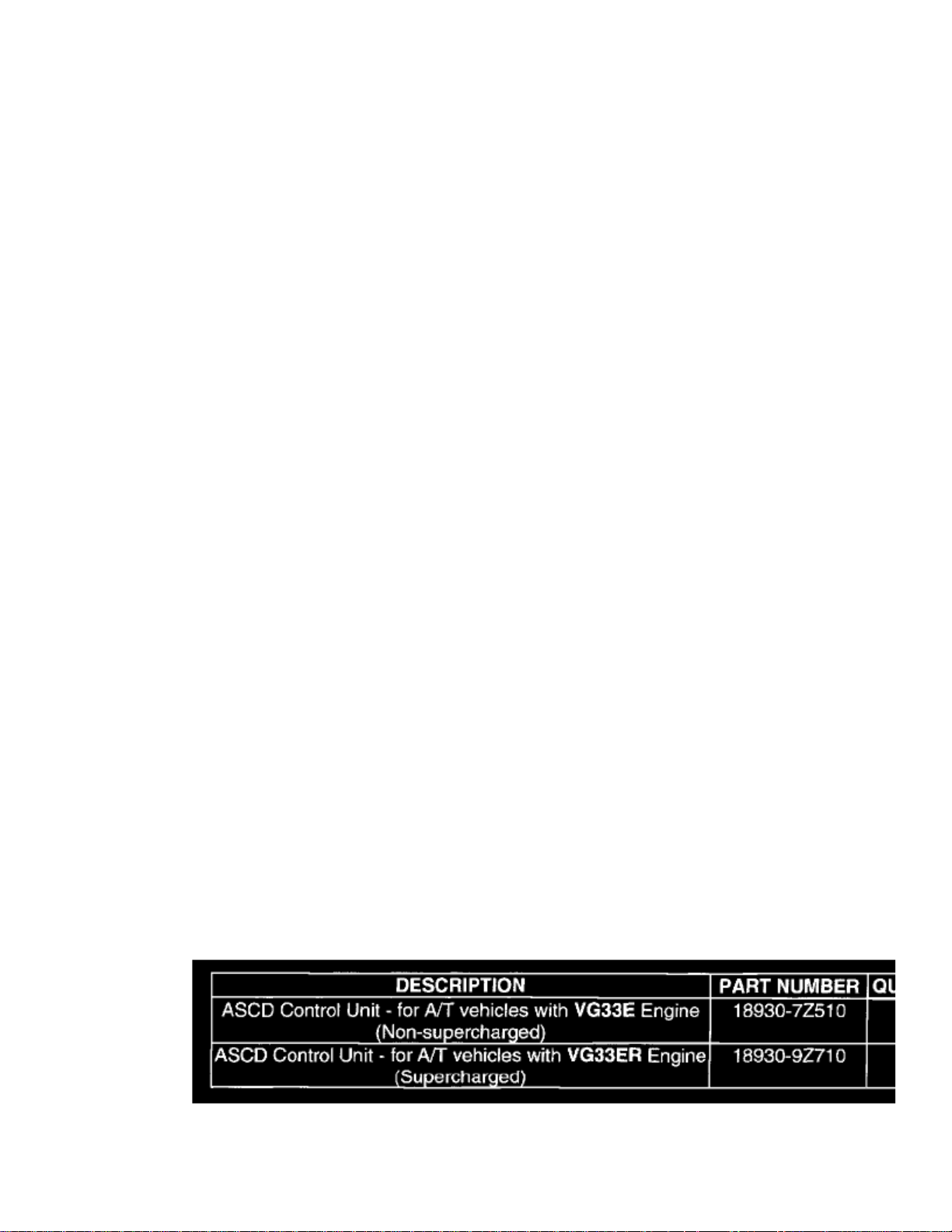
PARTS INFORMATION
Page 15

> Relays and Modules > Relays and Modules - Cruise Control > Cruise Control Module > Component Information > Technical Service Bulletins > All Technical Service
Bulletins for Cruise Control Module: > 03-037 > Apr > 03 > Cruise Control - Engine Surging/No A/T Upshift > Page 24
Xterra SE 2WD V6-3.3L (VG33E) (2002)
CLAIMS INFORMATION
Page 16
Submit a Separate Primary Failed Part (PP) line claim using the claims coding shown.
SERVICE PROCEDURE
Adjust the ASCD Wire
1. Verify the incident by a test drive. Drive the vehicle as described in the IF YOU CONFIRM section in this bulletin.
2.
Adjust the ASCD Wire. For details on ASCD Wire adjustment, refer to the EL section/Automatic Speed Control Device/ASCD Wire Adjustmentin the correct Service Manual.
:NOTE
Do riot skip the above step (2).
Remove and Replace the ASCD Control Unit
1.
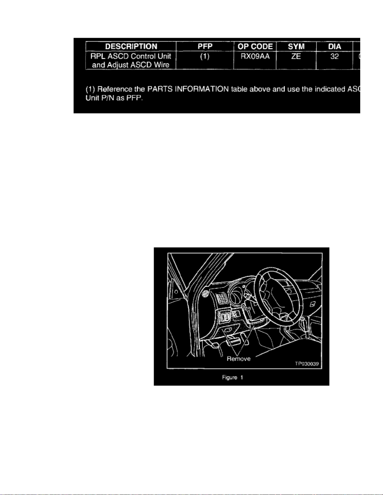
Remove the driver's side lower instrument panel (see Figure 1). For removal details, refer to the BT section/INSTRUMENT PANEL ASSEMBLYin the correct Service Manual.
Page 17

> Relays and Modules > Relays and Modules - Cruise Control > Cruise Control Module > Component Information > Technical Service Bulletins > All Technical Service
Bulletins for Cruise Control Module: > 03-037 > Apr > 03 > Cruise Control - Engine Surging/No A/T Upshift > Page 25
Xterra SE 2WD V6-3.3L (VG33E) (2002)
Page 18
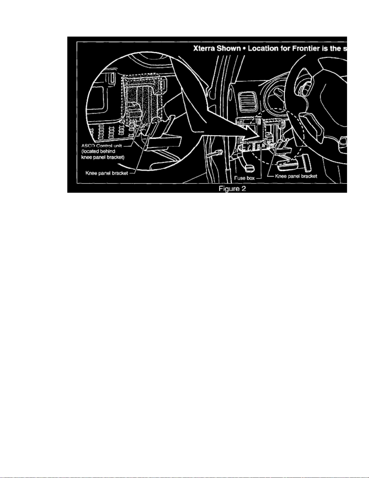
2. Remove the ASCD Control Unit and install the replacement Control Unit listed in the PARTS INFORMATION section (see Figure 2).
Refer to the EL section/ASCD/Component Parts and Harness Connector Location in the correct Service Manual for more information.
:NOTE
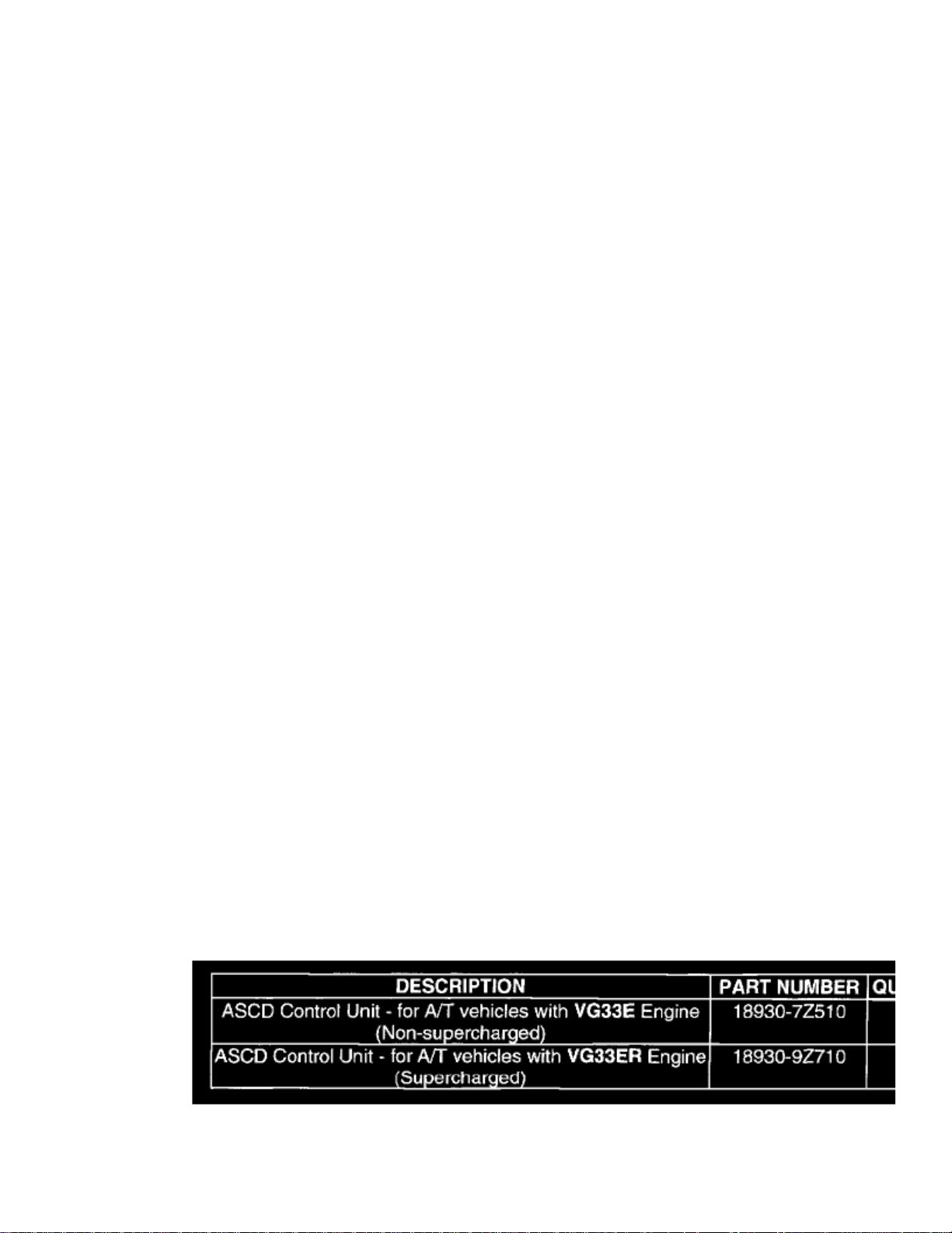
There are two ASCD Control Units available for A/T models, depending on engine type:
^ VG33E - Non-supercharged.
^ VG33ER - Supercharged.
See PARTS INFORMATION, when ordering.
3. Repeat the test drive. Drive the vehicle as described in the IF YOU CONFIRM section in this bulletin to verify the symptoms no longer exist.
Page 19

Page 20
> Relays and Modules > Relays and Modules - Cruise Control > Cruise Control Module > Component Information > Technical Service Bulletins > Customer Interest for Cruise Control Module: > 03-037 > Apr > 03 > Cruise
Control - Engine Surging/No A/T Upshift
Cruise Control Module: Customer InterestCruise Control - Engine Surging/No A/T Upshift
Classification:EC02-032
Reference:NTB03-037
Date:April 15, 2003
2001-2002 FRONTIER AND XTERRA VG33;"SURGE" OR NO A/T UPSHIFT WITH ASCD "ON"
APPLIED VEHICLES:2001-2002 Frontier (D22) - All with A/T2001-2002 Xterra (WD22) - All with A/T
APPLIED ENGINE:V16 (VG33E or VG33ER) only
APPLIED TRANSMISSION:Automatic Transmission only
IF YOU CONFIRM:
When using the Automatic Speed Control Device (ASCD - "Cruise Control" ON) at highway speeds of 55 - 75 mph, the vehicle shows either of thefollowing symptoms:
^ "surge" - a vehicle speed fluctuation as if the ASCD is "hunting" to set the speed, OR
^ after going uphill, Automatic Transmission upshift does not occur.
ACTIONS:
^ Adjust the ASCD Wire.
^ Remove and Replace the ASCD Control Unit.
: IMPORTANT
The purpose of ACTIONS (above) is to give you a quick idea of the work you will be performing. You MUST closely follow the entire ServiceProcedure as it contains information that is essential to successfully completing this repair.
PARTS INFORMATION
Page 21

> Relays and Modules > Relays and Modules - Cruise Control > Cruise Control Module > Component Information > Technical Service Bulletins > Customer Interest for
Cruise Control Module: > 03-037 > Apr > 03 > Cruise Control - Engine Surging/No A/T Upshift > Page 31
Xterra SE 2WD V6-3.3L (VG33E) (2002)
CLAIMS INFORMATION
Page 22
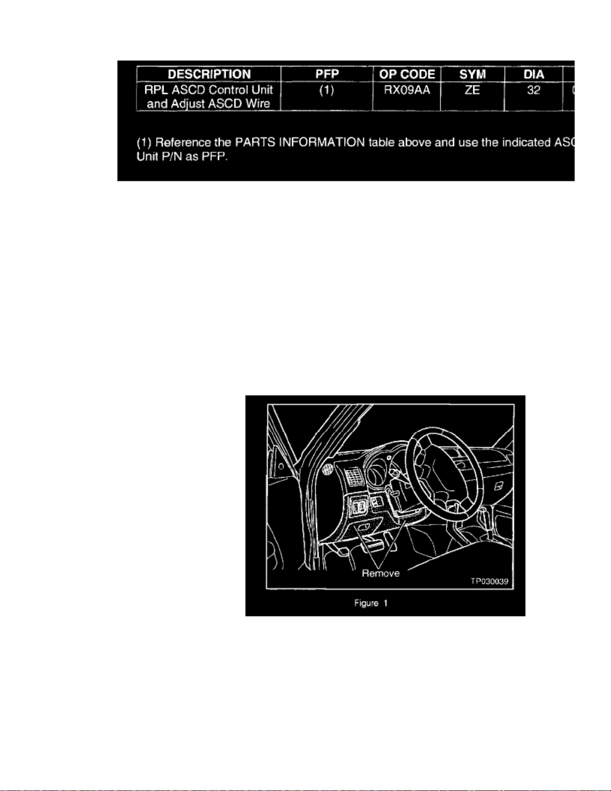
Submit a Separate Primary Failed Part (PP) line claim using the claims coding shown.
SERVICE PROCEDURE
Adjust the ASCD Wire
1. Verify the incident by a test drive. Drive the vehicle as described in the IF YOU CONFIRM section in this bulletin.
2.
Adjust the ASCD Wire. For details on ASCD Wire adjustment, refer to the EL section/Automatic Speed Control Device/ASCD Wire Adjustmentin the correct Service Manual.
:NOTE
Do riot skip the above step (2).
Remove and Replace the ASCD Control Unit
1.
Remove the driver's side lower instrument panel (see Figure 1). For removal details, refer to the BT section/INSTRUMENT PANEL ASSEMBLYin the correct Service Manual.
Page 23

> Relays and Modules > Relays and Modules - Cruise Control > Cruise Control Module > Component Information > Technical Service Bulletins > Customer Interest for
Cruise Control Module: > 03-037 > Apr > 03 > Cruise Control - Engine Surging/No A/T Upshift > Page 32
Xterra SE 2WD V6-3.3L (VG33E) (2002)
Page 24
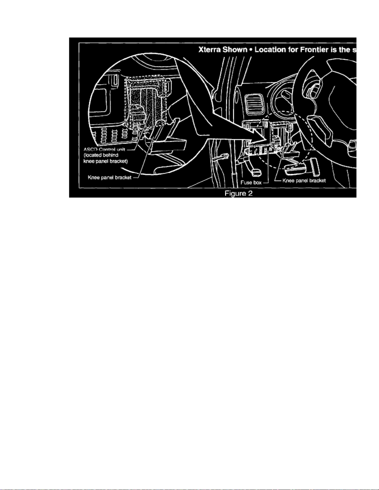
2. Remove the ASCD Control Unit and install the replacement Control Unit listed in the PARTS INFORMATION section (see Figure 2).
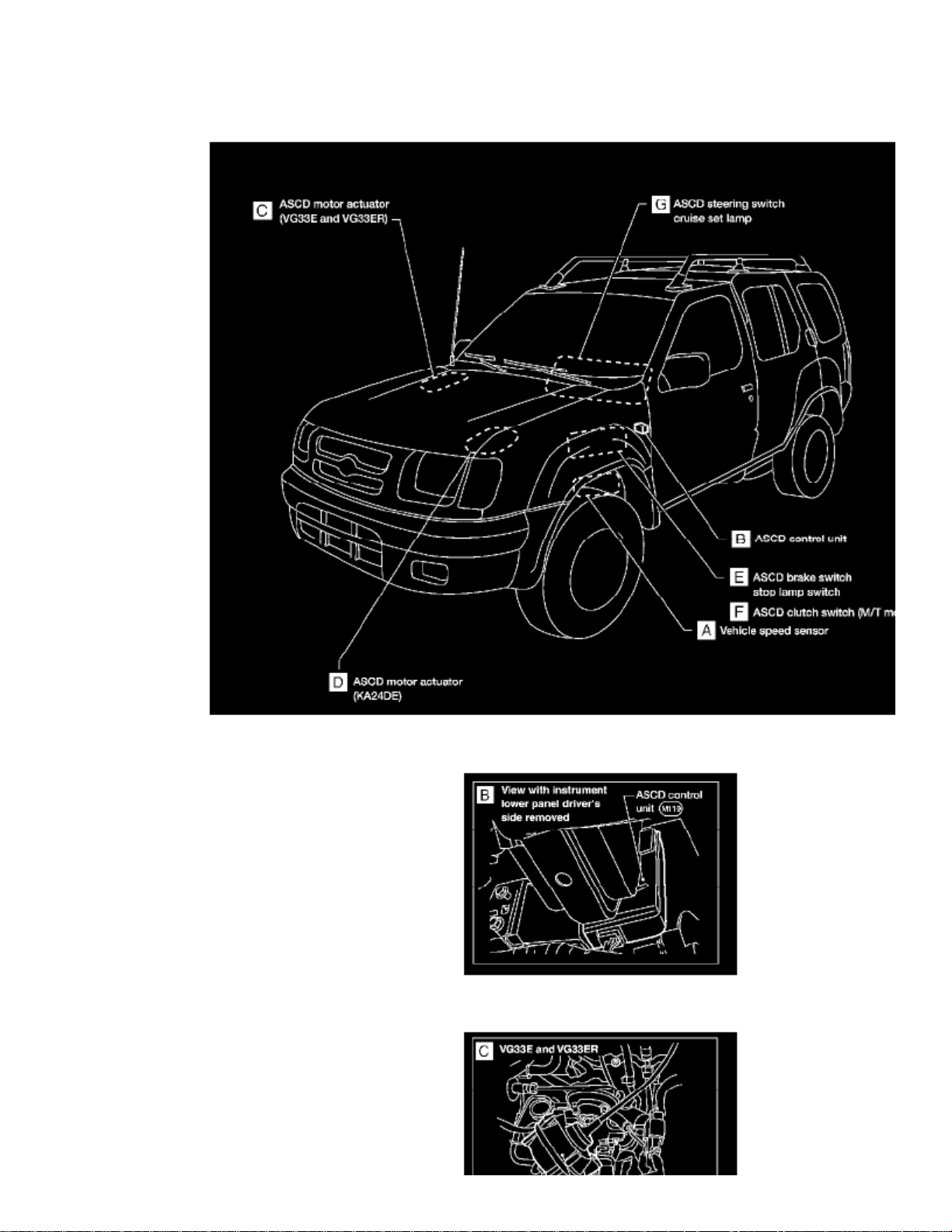
Refer to the EL section/ASCD/Component Parts and Harness Connector Location in the correct Service Manual for more information.
:NOTE
There are two ASCD Control Units available for A/T models, depending on engine type:
^ VG33E - Non-supercharged.
^ VG33ER - Supercharged.
See PARTS INFORMATION, when ordering.
3. Repeat the test drive. Drive the vehicle as described in the IF YOU CONFIRM section in this bulletin to verify the symptoms no longer exist.
Page 25

Page 26
> Relays and Modules > Relays and Modules - Cruise Control > Cruise Control Module > Component Information > Technical Service Bulletins > Page 33
Cruise Control Module: Locations
Component Locations Overall View
Component View B
Page 27

> Relays and Modules > Relays and Modules - Cruise Control > Cruise Control Module > Component Information > Technical Service Bulletins > Page 34
Xterra SE 2WD V6-3.3L (VG33E) (2002)
Component View C
Page 28
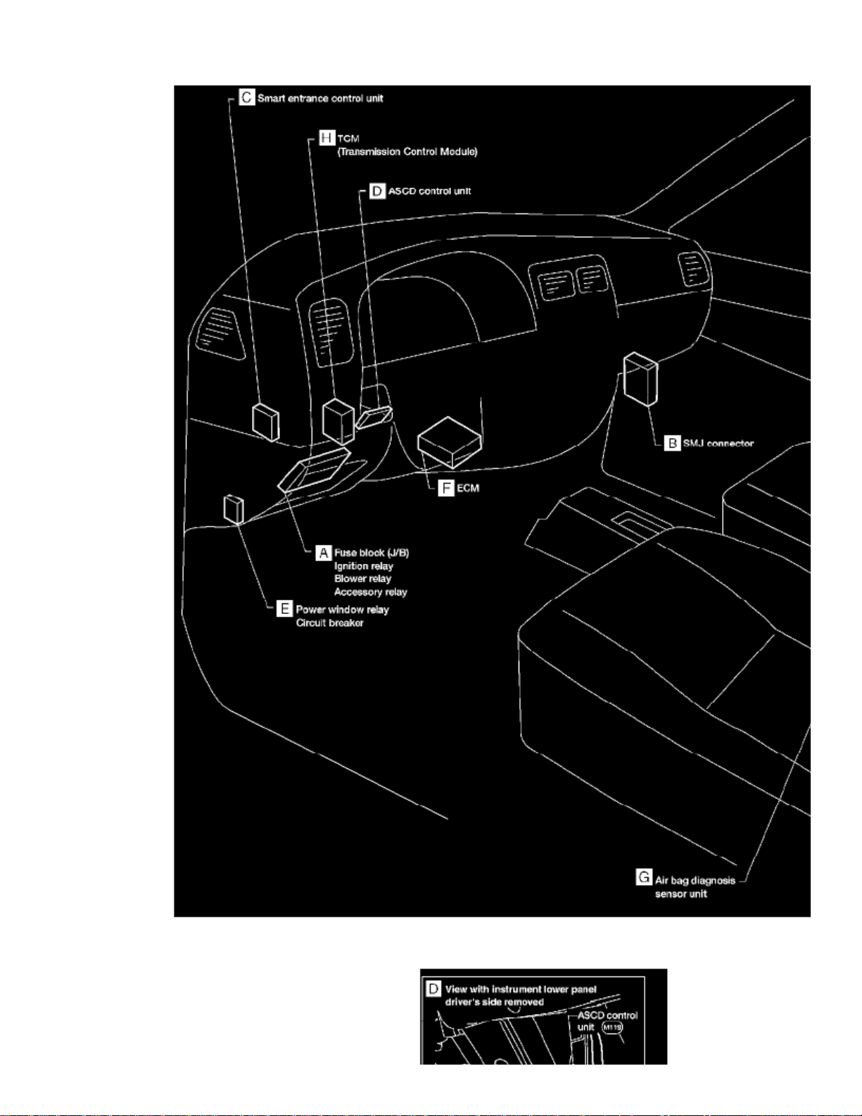
Passenger Compartment Component Locations Overall View
Page 29

Component View D
Page 30
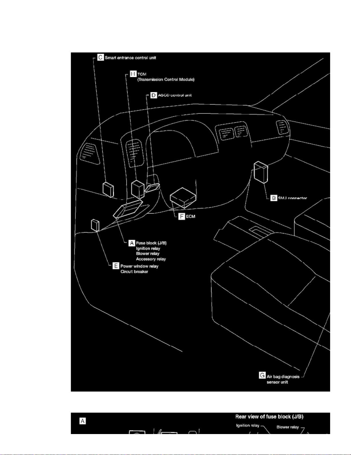
> Relays and Modules > Relays and Modules - HVAC > Blower Motor Relay > Component Information > Locations
Blower Motor Relay: Locations
Passenger Compartment Component Locations Overall View
Page 31
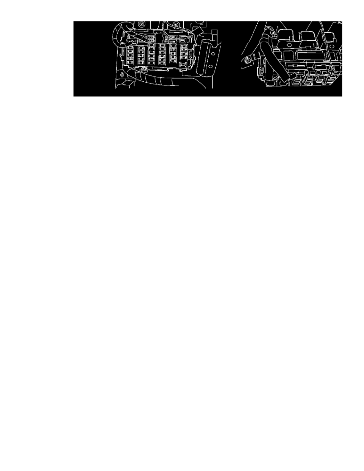
> Relays and Modules > Relays and Modules - HVAC > Blower Motor Relay > Component Information > Locations > Page 39
Xterra SE 2WD V6-3.3L (VG33E) (2002)
Page 32

Component View A
Page 33

Page 34
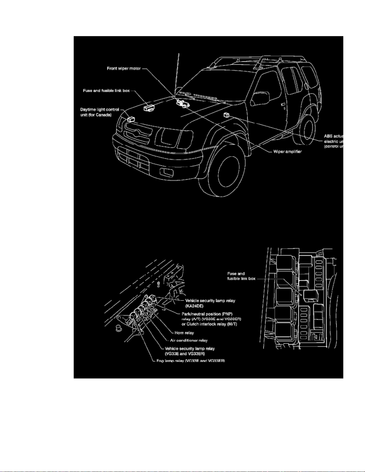
> Relays and Modules > Relays and Modules - HVAC > Compressor Clutch Relay > Component Information > Locations
Engine Compartment
Page 35

Page 36
> Relays and Modules > Relays and Modules - HVAC > Compressor Clutch Relay > Component Information > Locations > Page 43
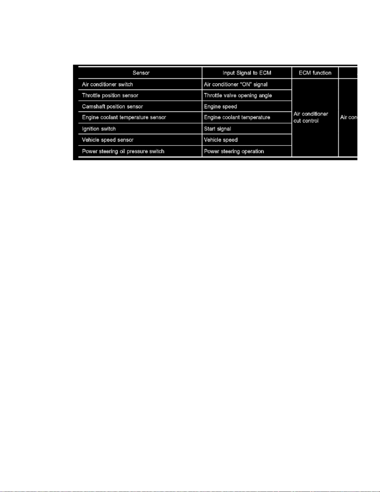
Compressor Clutch Relay: Description and Operation
DESCRIPTION
Input/Output Signal Chart
System Description
This system improves engine operation when the air conditioner is used. Under the following conditions, the air conditioner is turned OFF.
- When the accelerator pedal is fully depressed.
- When cranking the engine.
- At high engine speeds.
- When the engine coolant temperature becomes excessively high.
- When operating power steering during low engine speed or low vehicle speed.
- When engine speed is excessively low.
Page 37

Page 38
> Relays and Modules > Relays and Modules - HVAC > Compressor Clutch Relay > Component Information > Locations > Page 44
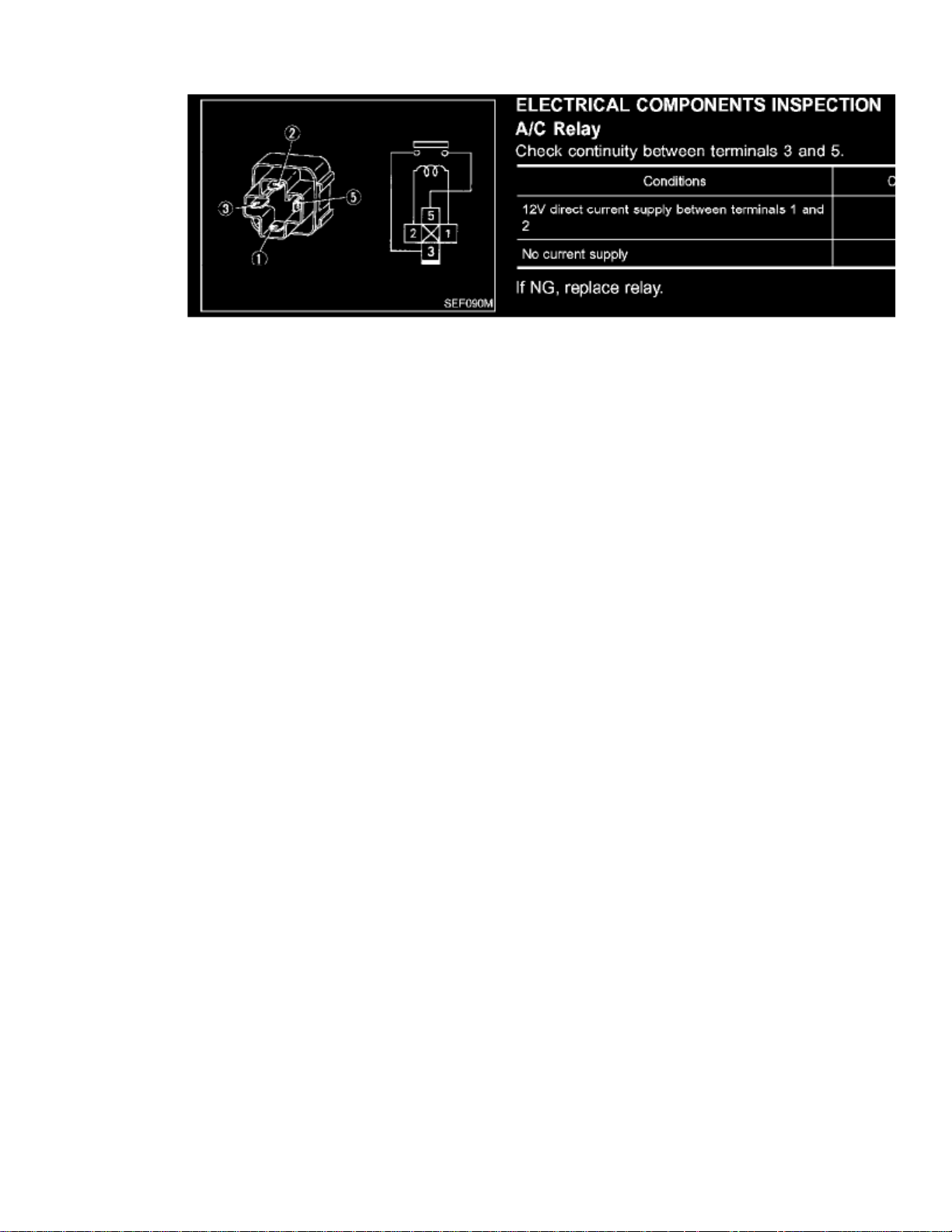
A/C Relay
Page 39

Page 40
> Relays and Modules > Relays and Modules - HVAC > Control Module HVAC > Component Information > Testing and Inspection
Control Module HVAC: Testing and Inspection
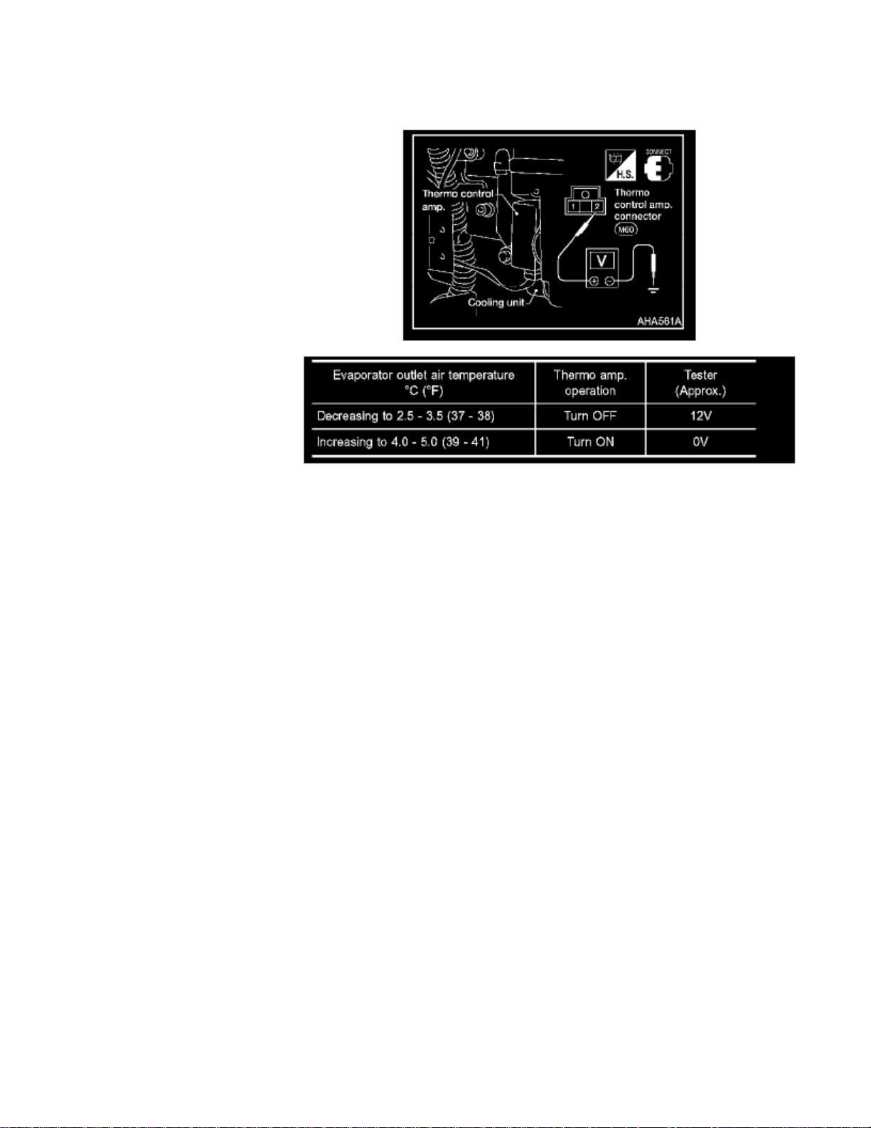
Thermo Control Amp.
1. Run engine and operate A/C system.2. Connect the voltmeter from harness side.3. Check the thermo control amp. operation as shown in the table.
Page 41

Page 42
> Relays and Modules > Relays and Modules - Instrument Panel > Instrument Panel Control Module > Component Information > Diagrams > Diagram Information and Instructions
Instrument Panel Control Module: Diagram Information and Instructions
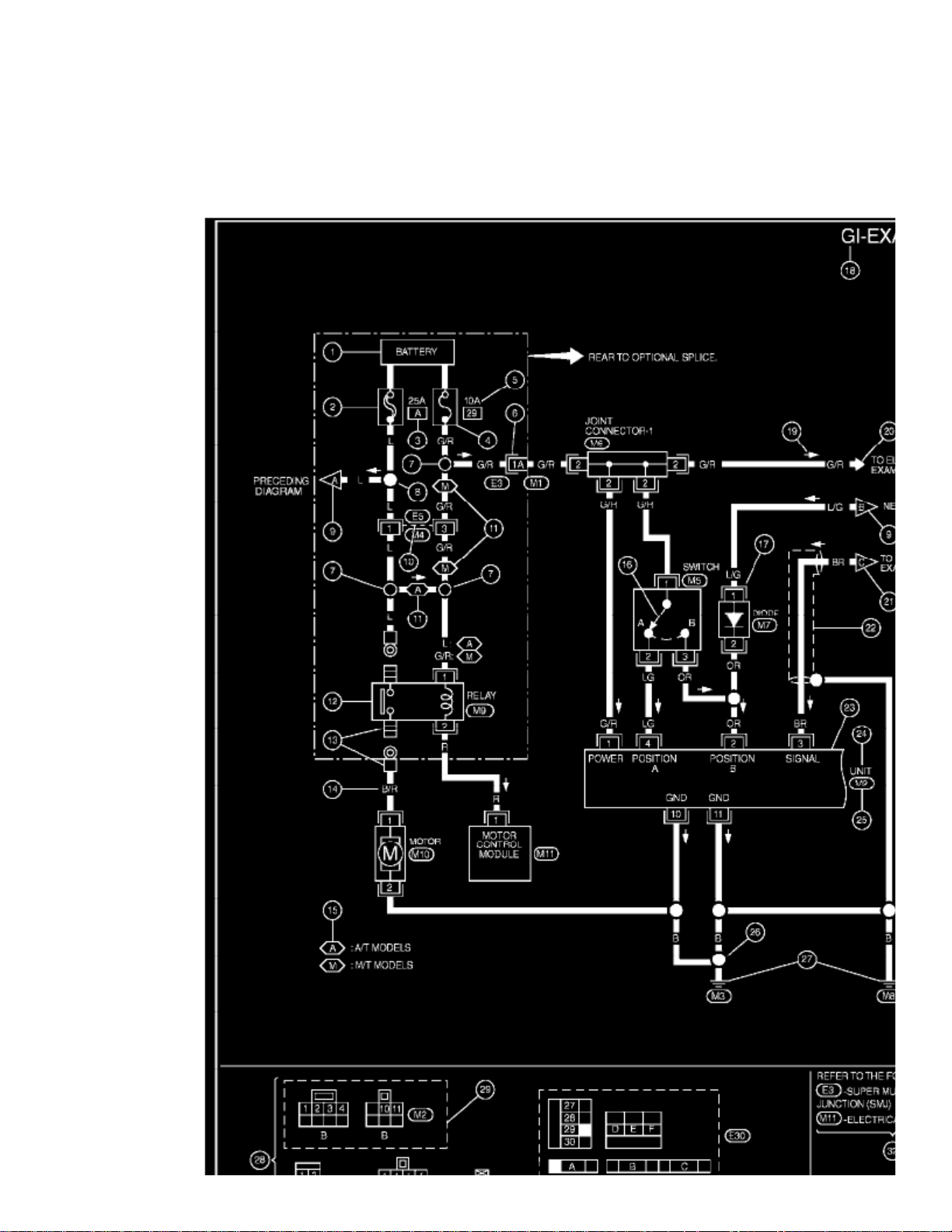
How to Read Wiring Diagrams
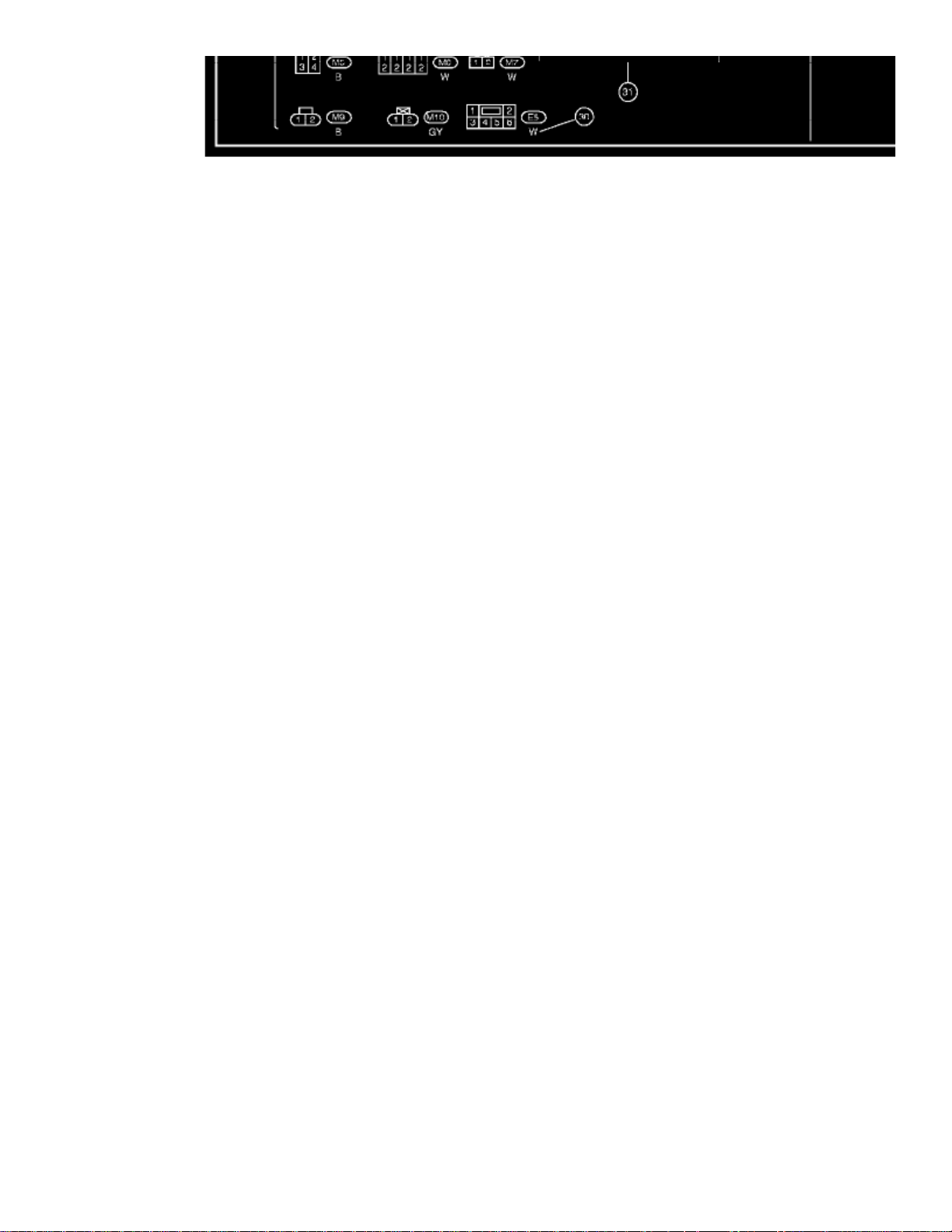
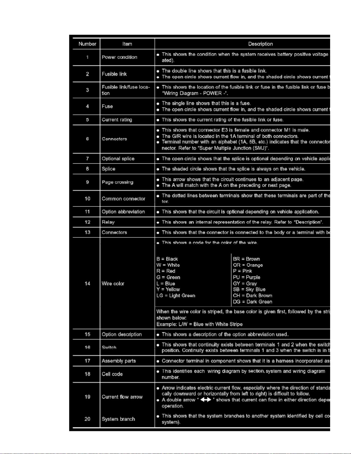
HOW TO READ WIRING DIAGRAMS
Page 43
> Relays and Modules > Relays and Modules - Instrument Panel > Instrument Panel Control Module > Component Information > Diagrams > Diagram Information and
Instructions > Page 53
Xterra SE 2WD V6-3.3L (VG33E) (2002)
SAMPLE/WIRING DIAGRAM - EXAMPL -
- For detail, refer to following "DESCRIPTION".
Page 44
Page 45

> Relays and Modules > Relays and Modules - Instrument Panel > Instrument Panel Control Module > Component Information > Diagrams > Diagram Information and
Instructions > Page 54
Xterra SE 2WD V6-3.3L (VG33E) (2002)
Part 1
Page 46
Part 2
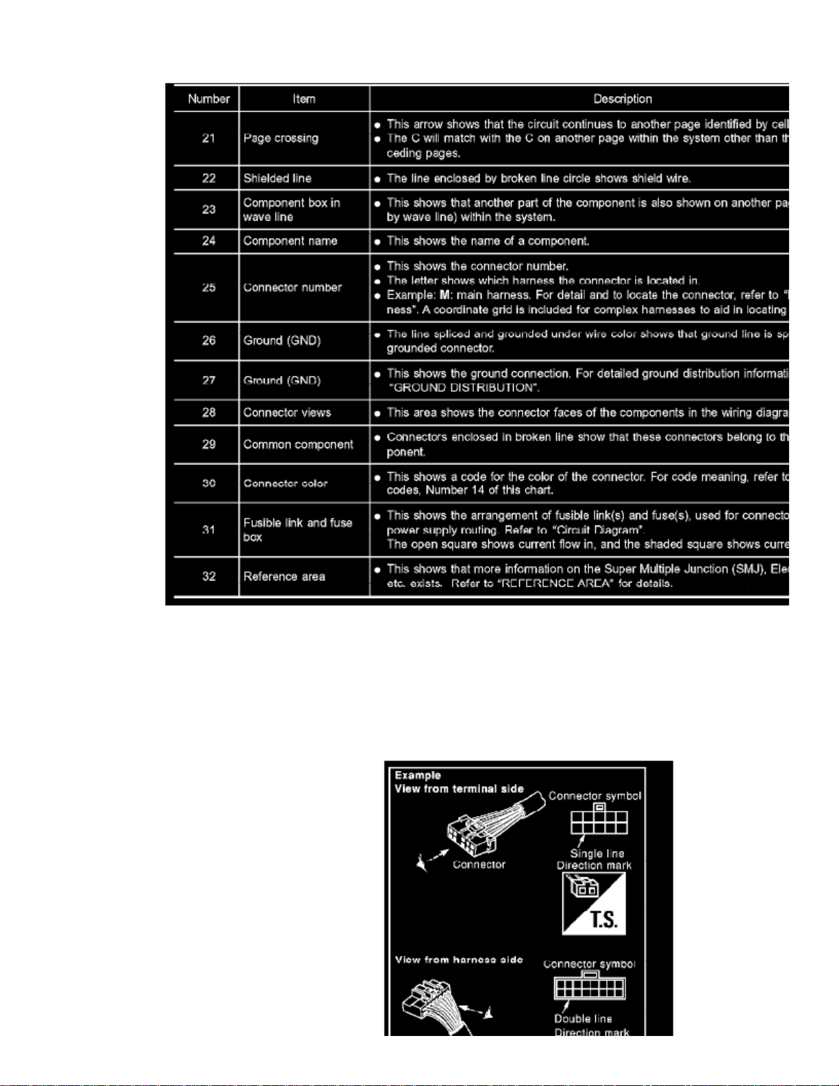
Description
CONNECTOR SYMBOLS
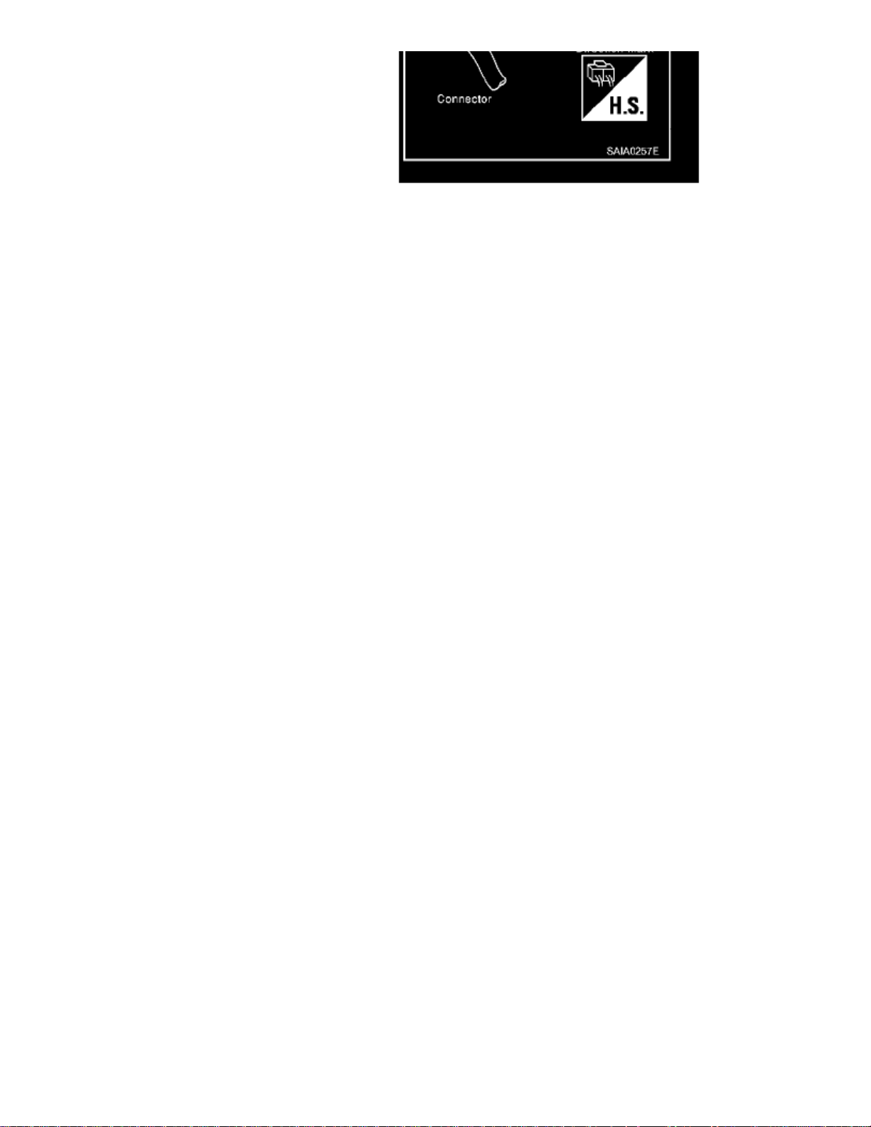
Most of connector symbols in wiring diagrams are shown from the terminal side.
Page 47
> Relays and Modules > Relays and Modules - Instrument Panel > Instrument Panel Control Module > Component Information > Diagrams > Diagram Information and
Instructions > Page 55
Xterra SE 2WD V6-3.3L (VG33E) (2002)
- Connector symbols shown from the terminal side are enclosed by a single line and followed by the direction mark.
- Connector symbols shown from the harness side are enclosed by a double line and followed by the direction mark.
- Certain systems and components, especially related to OBD, may use a new style slide-locking type harness connector. For description and how to
Page 48
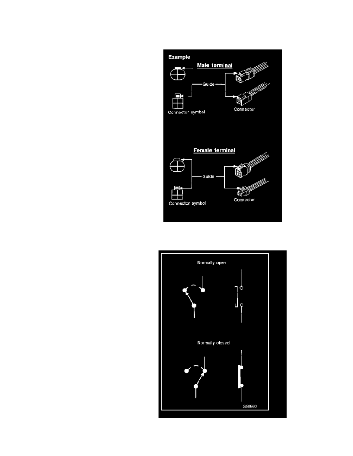
disconnect, refer to "Description".
Male and female terminalsConnector guides for male terminals are shown in black and female terminals in white in wiring diagrams.
Page 49

> Relays and Modules > Relays and Modules - Instrument Panel > Instrument Panel Control Module > Component Information > Diagrams > Diagram Information and
Instructions > Page 56
Xterra SE 2WD V6-3.3L (VG33E) (2002)
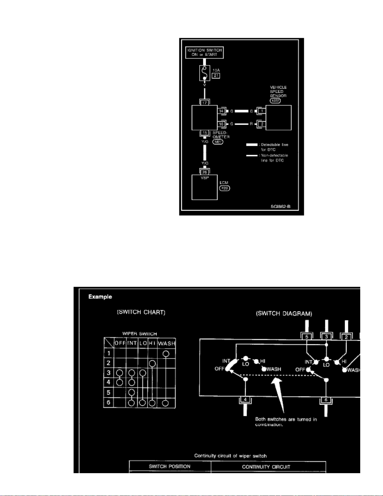
SWITCH POSITIONS
Switches are shown in wiring diagrams as if the vehicle is in the "normal" condition.A vehicle is in the "normal" condition when:
- ignition switch is OFF,
- doors, hood and trunk lid/back door are closed,
- pedals are not depressed, and
- parking brake is released.
Page 50
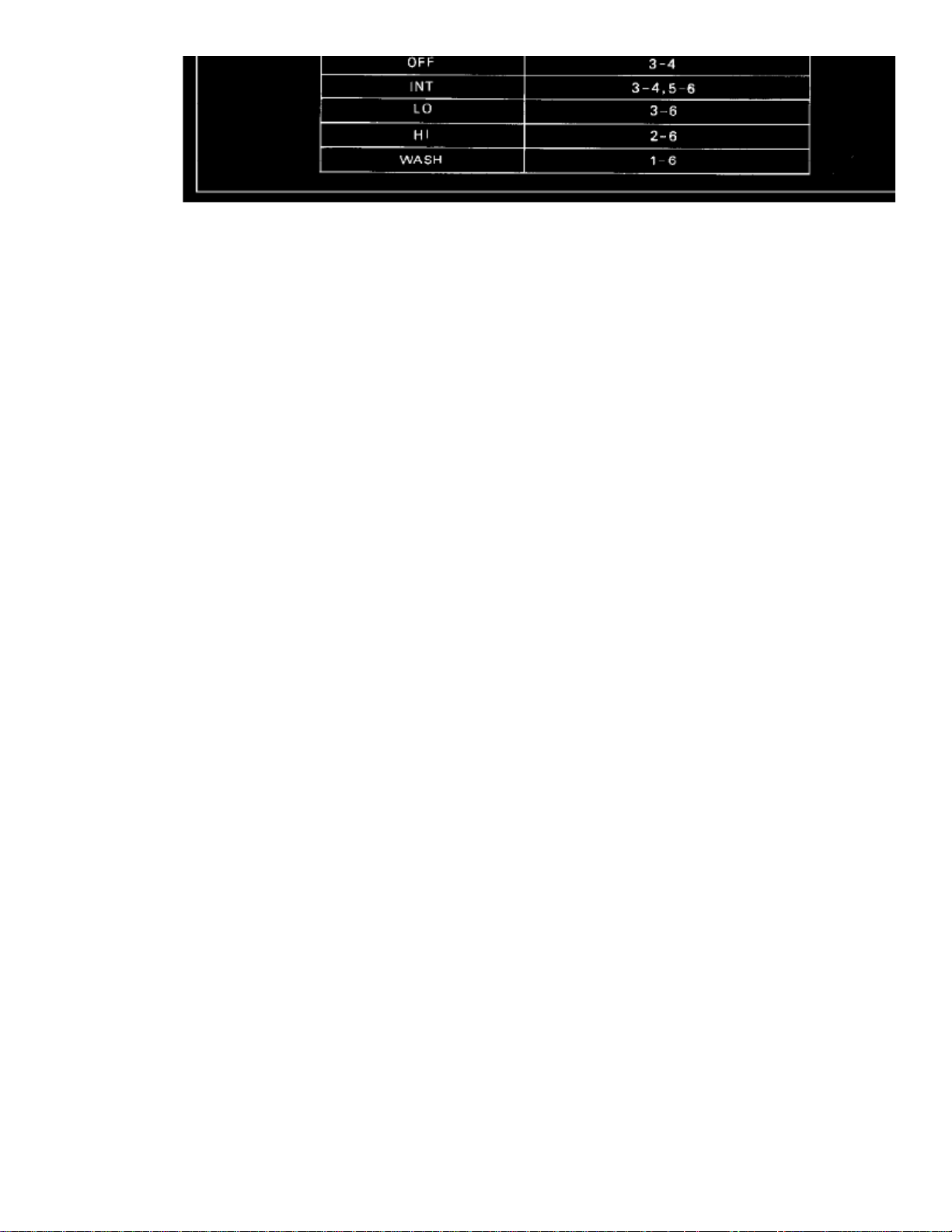
DETECTABLE LINES AND NON-DETECTABLE LINES
In some wiring diagrams, two kinds of lines, representing wires, with different weight are used.
A line with regular weight (wider line) represents a "detectable line for DTC (Diagnostic Trouble Code)". A "detectable line for DTC" is a circuitin which ECM can detect its malfunctions with the on board diagnostic system.
A line with less weight (thinner line) represents a "non-detectable line for DTC". A "non-detectable line for DTC" is a circuit in which ECMcannot detect its malfunctions with the on board diagnostic system.
Page 51
> Relays and Modules > Relays and Modules - Instrument Panel > Instrument Panel Control Module > Component Information > Diagrams > Diagram Information and
Instructions > Page 57
Xterra SE 2WD V6-3.3L (VG33E) (2002)
MULTIPLE SWITCH
Page 52
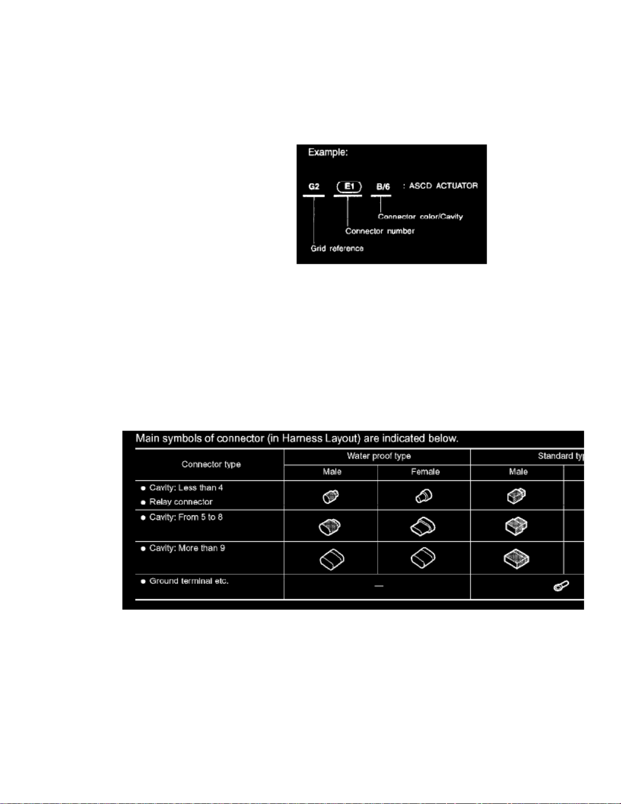
The continuity of multiple switch is described in two ways as shown below.
- The switch chart is used in schematic diagrams.
- The switch diagram is used in wiring diagrams.
How to Read Harness Layout
The following Harness Layouts use a map style grid to help locate connectors on the drawings:
- Main Harness
- Engine Room Harness (Engine Compartment)
- Engine Control Harness
TO USE THE GRID REFERENCE
1. Find the desired connector number on the connector list.2. Find the grid reference.3. On the drawing, find the crossing of the grid reference letter column and number row.4. Find the connector number in the crossing zone.5. Follow the line (if used) to the connector.
Connector Symbol
Harness Connector Descriptions
Description
HARNESS CONNECTOR (TAB-LOCKING TYPE)
- The tab-locking type connectors help prevent accidental looseness or disconnection.
- The tab-locking type connectors are disconnected by pushing or lifting the locking tab(s). Refer to the illustration.
Page 53

> Relays and Modules > Relays and Modules - Instrument Panel > Instrument Panel Control Module > Component Information > Diagrams > Diagram Information and
Instructions > Page 58
Xterra SE 2WD V6-3.3L (VG33E) (2002)
Page 54
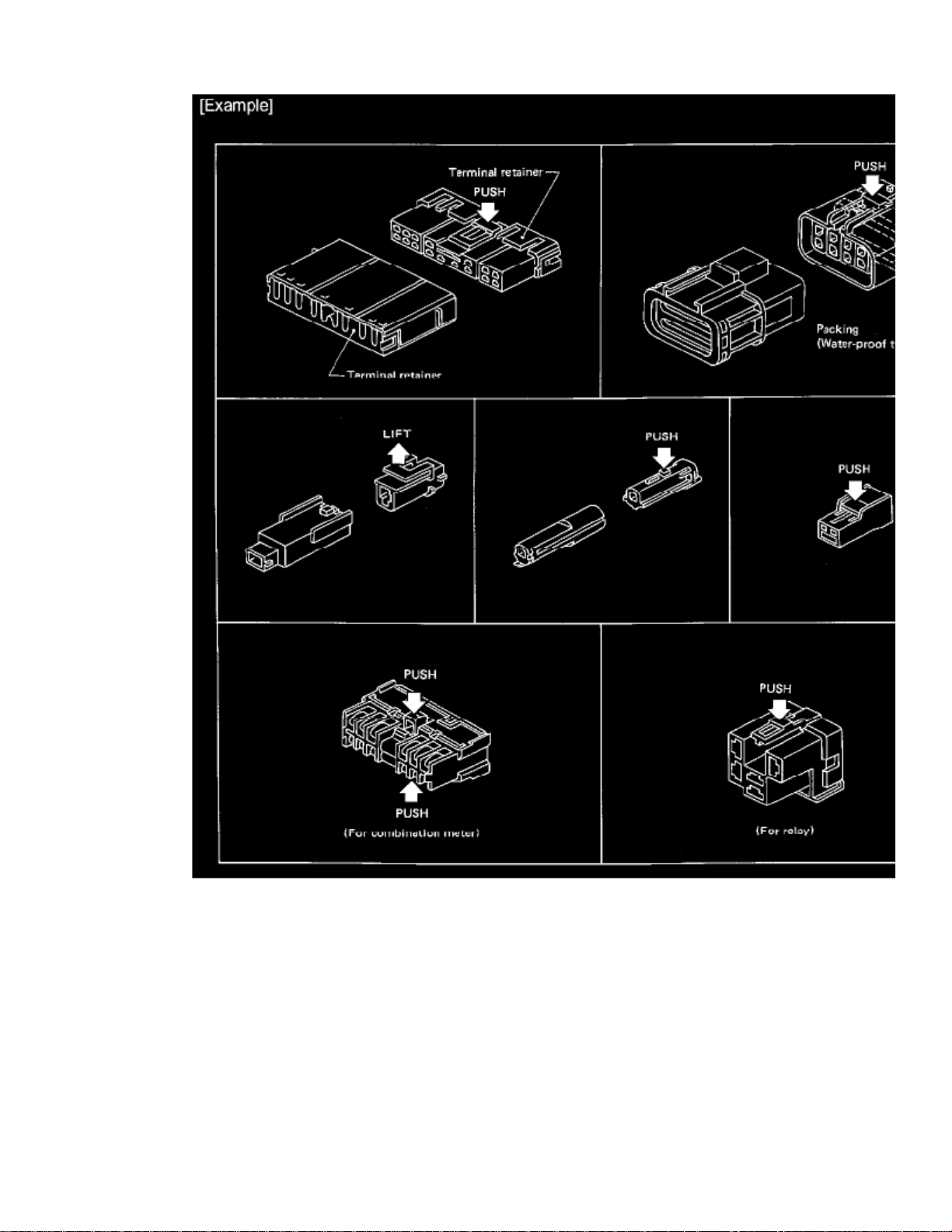
Do not pull the harness when disconnecting the connector.CAUTION:
HARNESS CONNECTOR (SLIDE-LOCKING TYPE)
- A new style slide-locking connector is used on certain systems and components, especially those related to OBD.
- The slide-locking type connectors help prevent incomplete locking and accidental looseness or disconnection.
- The slide-locking type connectors are disconnected by pushing or pulling the slider. Refer to the illustration.
Page 55

> Relays and Modules > Relays and Modules - Instrument Panel > Instrument Panel Control Module > Component Information > Diagrams > Diagram Information and
Instructions > Page 59
Xterra SE 2WD V6-3.3L (VG33E) (2002)
Page 56
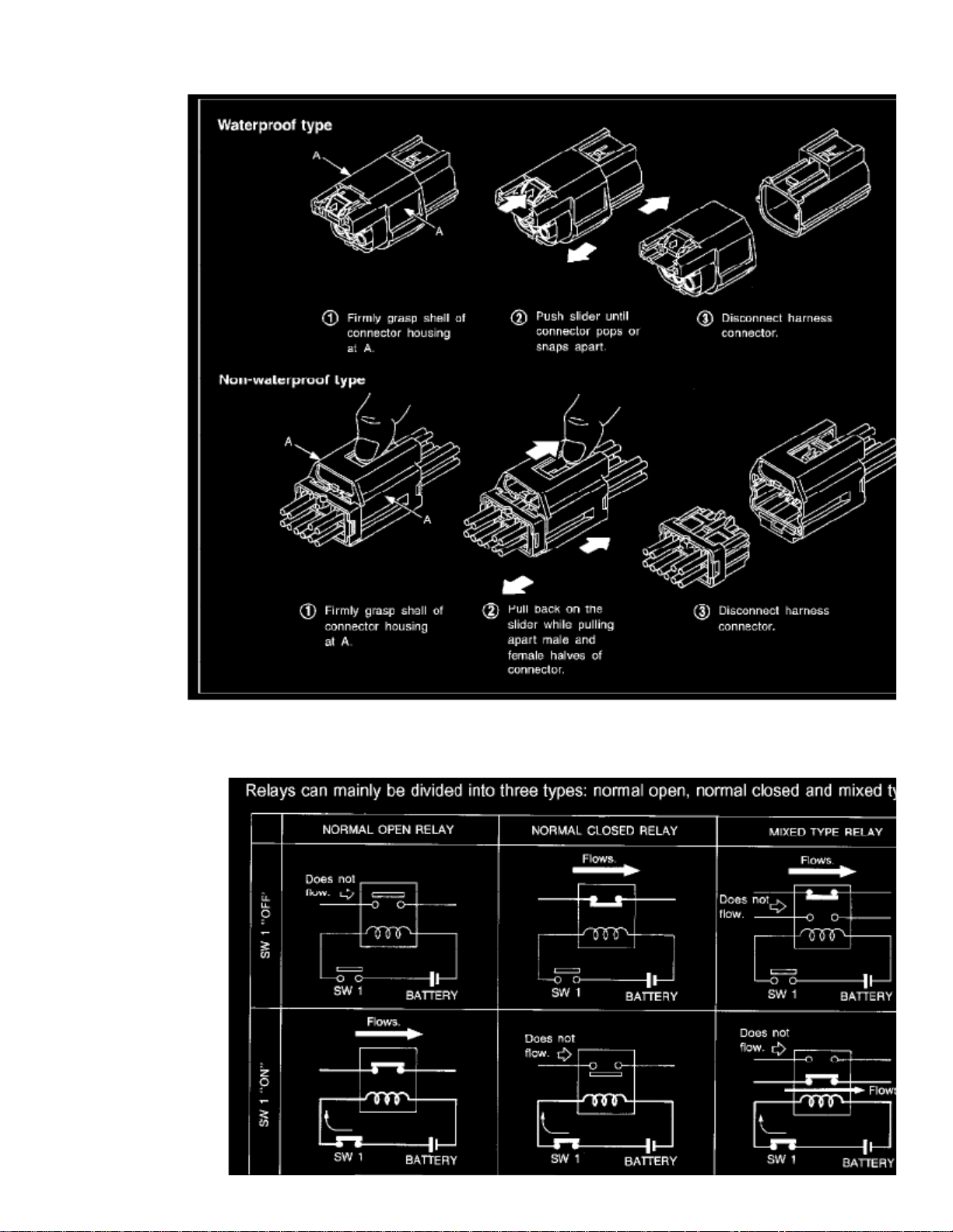
CAUTION:
Do not pull the harness or wires when disconnecting the connector. Be careful not to damage the connector support bracket whendisconnecting the connector.
Page 57

> Relays and Modules > Relays and Modules - Instrument Panel > Instrument Panel Control Module > Component Information > Diagrams > Diagram Information and
Instructions > Page 60
Xterra SE 2WD V6-3.3L (VG33E) (2002)
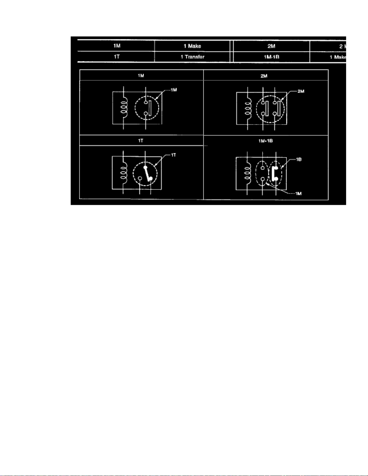
Normal Open, Normal Closed And Mixed Type Relays
Page 58
Page 59

> Relays and Modules > Relays and Modules - Instrument Panel > Instrument Panel Control Module > Component Information > Diagrams > Diagram Information and
Instructions > Page 61
Xterra SE 2WD V6-3.3L (VG33E) (2002)
Page 60
Page 61

> Relays and Modules > Relays and Modules - Instrument Panel > Instrument Panel Control Module > Component Information > Diagrams > Diagram Information and
Instructions > Page 62
Xterra SE 2WD V6-3.3L (VG33E) (2002)
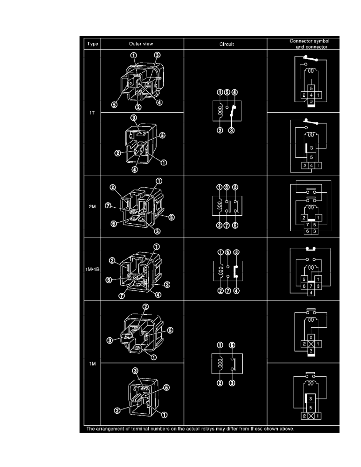
Types Of Standardized Relays Part 2
Wire Color Code Identification
Wiring Color Code
B
W
R
G
= Black = White = Red = Green = BlueL
Page 62

Y
LG
BR
OR O
P
PU V
GY GR
SB
CH
= Yellow = Light Green = Brown or = Orange = Pink or (violet) = Purple or = Grey = Sky Blue = Dark Brown = Dark GreenDG
Page 63

> Relays and Modules > Relays and Modules - Instrument Panel > Instrument Panel Control Module > Component Information > Diagrams > Diagram Information and
Instructions > Page 63
Xterra SE 2WD V6-3.3L (VG33E) (2002)
Page 64
Page 65

> Relays and Modules > Relays and Modules - Instrument Panel > Instrument Panel Control Module > Component Information > Diagrams > Diagram Information and
Instructions > Page 64
Xterra SE 2WD V6-3.3L (VG33E) (2002)
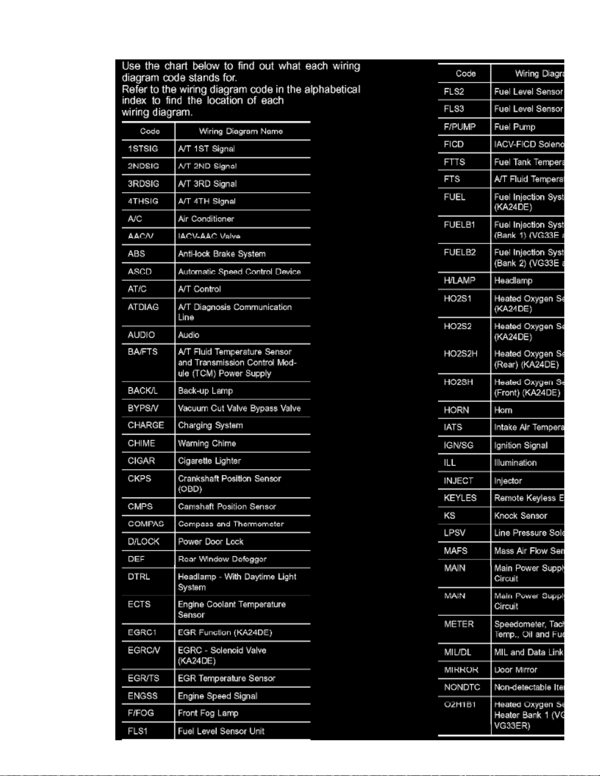
Wiring Diagram Codes (Cell Codes) Part 1
Page 66
Page 67

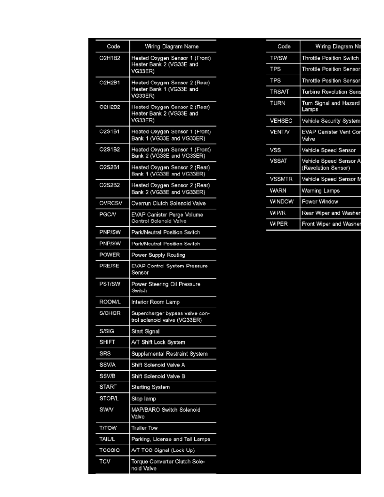
Wiring Diagram Codes (Cell Codes) Part 2
Page 68
> Relays and Modules > Relays and Modules - Instrument Panel > Instrument Panel Control Module > Component Information > Diagrams > Diagram Information and Instructions > Page 65
Instrument Panel Control Module: Diagnostic Aids
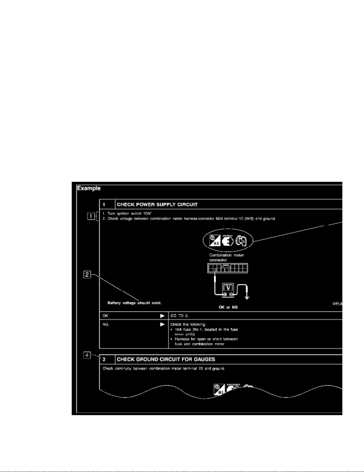
How to Follow Test Groups in Trouble Diagnosis
Trouble diagnoses indicates work procedures required to diagnose problems effectively. Observe the following instructions before diagnosing.NOTE:
1. Before performing trouble diagnoses, read the "Preliminary Check", the "Symptom Chart" or the "Work Flow".2. After repairs, re-check that the problem has been completely eliminated.3. Refer to Component Parts and Harness Connector Location for the Systems described in each section for identification/location of components and
harness connectors.
4. Refer to the Circuit Diagram for quick pinpoint check. If you need to check circuit continuity between harness connectors in more detail, such as
when a sub-harness is used, refer to Wiring Diagram in each individual section and Harness Layout for identification of harness connectors.
5. When checking circuit continuity, ignition switch should be "OFF".6. Before checking voltage at connectors, check battery voltage.7. After accomplishing the Diagnostic Procedures and Electrical Components Inspection, make sure that all harness connectors are reconnected as
they were.
How to Follow Test Groups in Trouble Diagnoses
1. Work and diagnostic procedure
Start to diagnose a problem using procedures indicated in enclosed test groups.
Page 69

> Relays and Modules > Relays and Modules - Instrument Panel > Instrument Panel Control Module > Component Information > Diagrams > Diagram Information and
Instructions > Page 66
Xterra SE 2WD V6-3.3L (VG33E) (2002)
2. Questions and required results.
Questions and required results are indicated in bold type in test group.
11 - 14 V
12 V 0 V
The meanings are as follows:a. Battery voltage -> or approximately b. Voltage: Approximately -> Less than c. Resistance: Continuity should exist -> Approximately 1 V 0 ohm
3. Symbol used in illustration
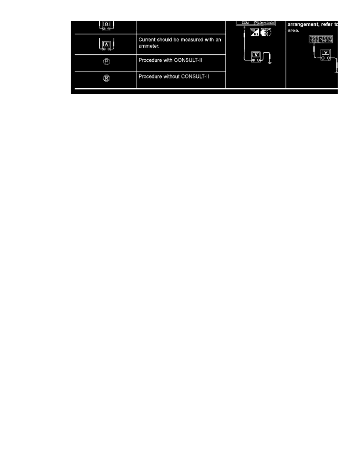
Symbols included in illustrations refer to measurements or procedures. Before diagnosing a problem, familiarize yourself with each symbol. Referto "CONNECTOR SYMBOLS" and "Key to Symbols Signifying Measurements or Procedures".
Page 70
4. Action items
Next action for each test group is indicated based on result of each question. Test group number is shown in the left upper portion of each testgroup.
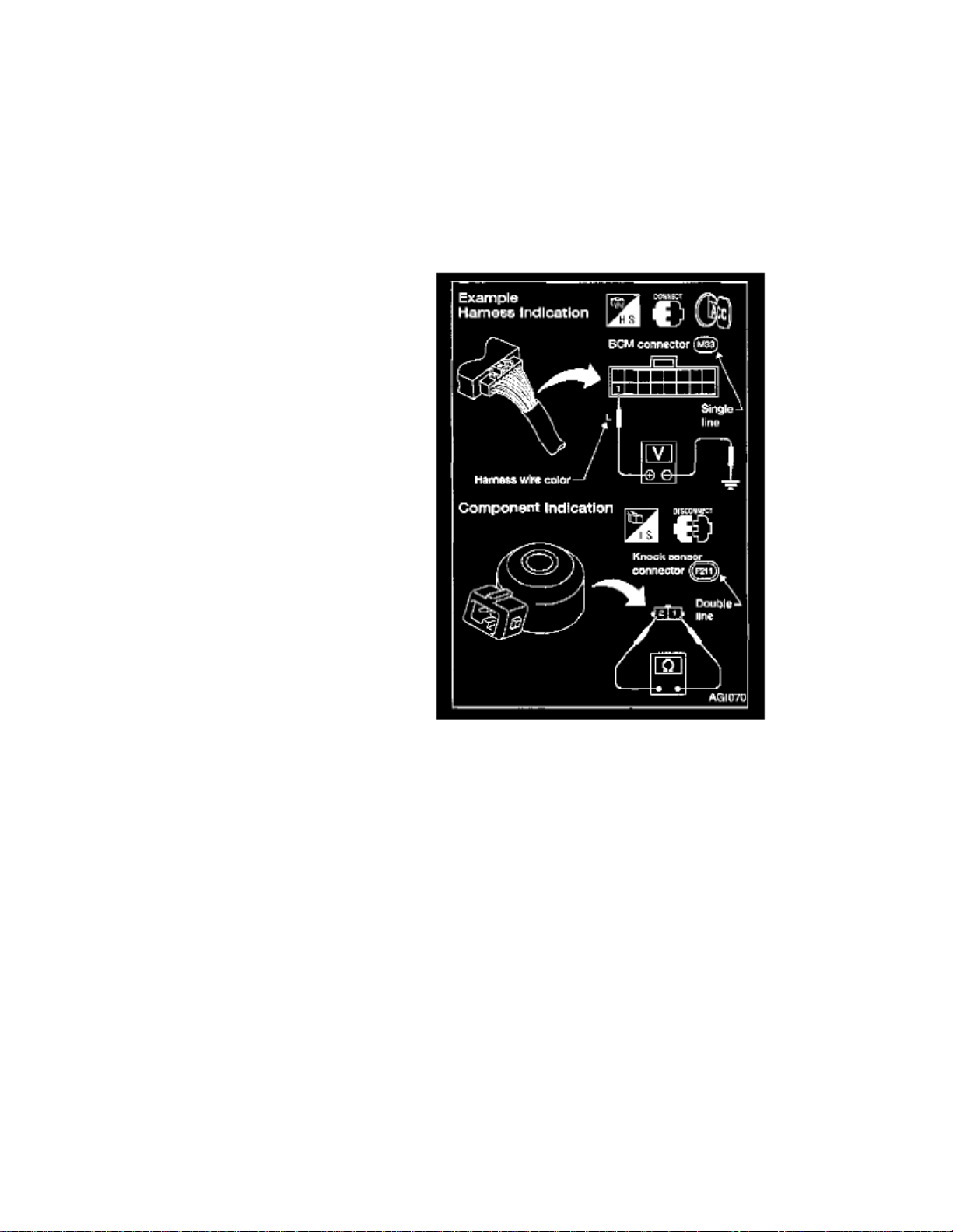
Harness Wire Color and Connector Number Indication
There are two types of harness wire color and connector number indication.
TYPE 1: HARNESS WIRE COLOR AND CONNECTOR NUMBER ARE SHOWN IN ILLUSTRATION
- Letter designations next to test meter probe indicate harness wire color.
- Connector numbers in a single circle (e.g. M33) indicate harness connectors.
- Connector numbers in a double circle indicate component connectors.
Page 71

> Relays and Modules > Relays and Modules - Instrument Panel > Instrument Panel Control Module > Component Information > Diagrams > Diagram Information and
Instructions > Page 67
Xterra SE 2WD V6-3.3L (VG33E) (2002)
Page 72
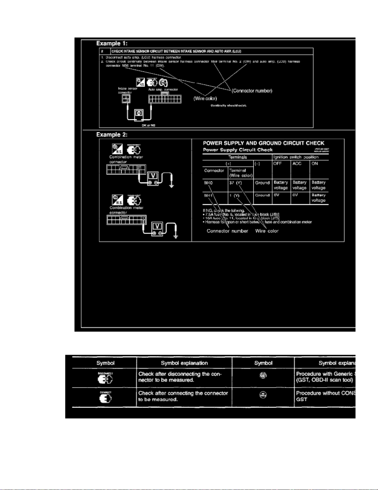
TYPE 2: HARNESS WIRE COLOR AND CONNECTOR NUMBER ARE SHOWN IN TEXT
Part 1
Page 73

> Relays and Modules > Relays and Modules - Instrument Panel > Instrument Panel Control Module > Component Information > Diagrams > Diagram Information and
Instructions > Page 68
Xterra SE 2WD V6-3.3L (VG33E) (2002)
Page 74
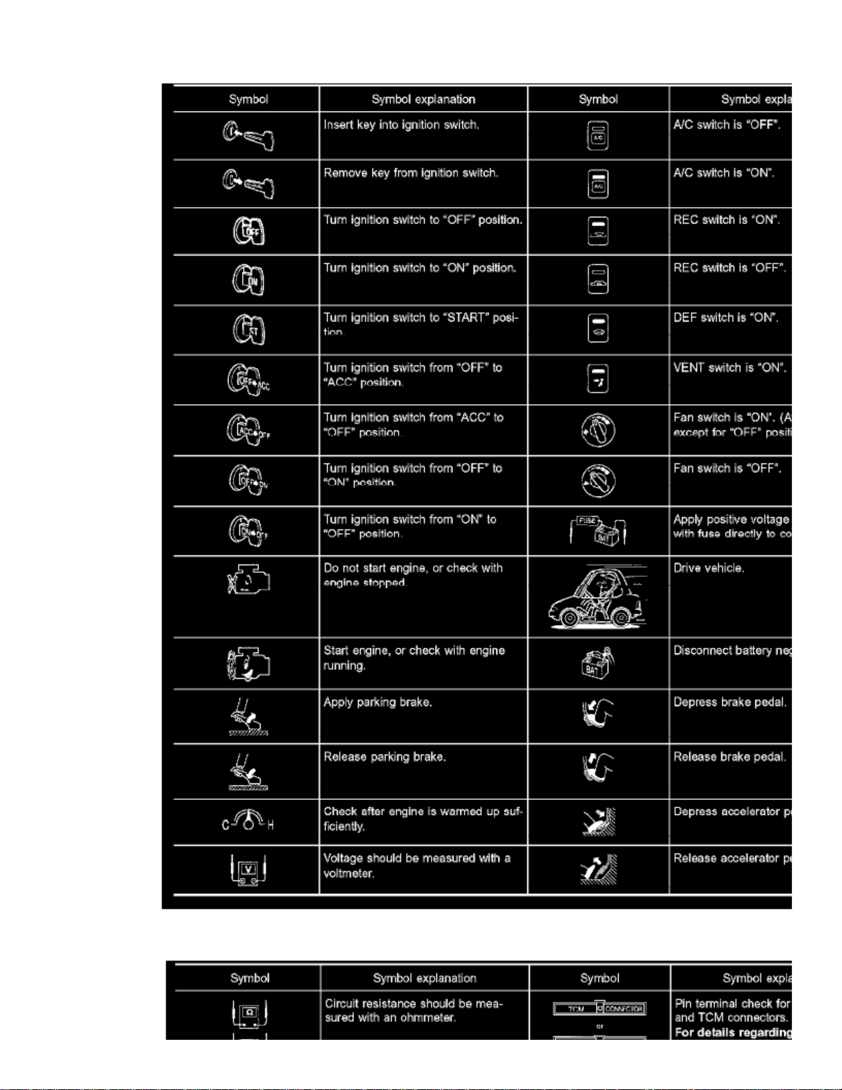
Part 2
Page 75
> Relays and Modules > Relays and Modules - Instrument Panel > Instrument Panel Control Module > Component Information > Diagrams > Diagram Information and
Instructions > Page 69
Xterra SE 2WD V6-3.3L (VG33E) (2002)
Page 76
Part 3
Key to Symbols Signifying Measurements or Procedures
Introduction
INTRODUCTION
In general testing electrical circuits is an easy task if it is approached in a logical and organized method. Before beginning it is important to have allavailable information on the system to be tested. Also get a thorough understanding of system operation. Then you will be able to use the appropriateequipment and follow the correct test procedure.
OPEN:
A circuit is Open when there is no continuity through a section of the circuit.
There are two types of shorts.SHORT:
SHORT CIRCUIT -
When a circuit contacts another circuit and causes the normal resistance to change.When a circuit contacts a ground source and grounds the circuit.SHORT TO GROUND -
You may have to simulate vehicle vibrations while testing electrical components. Gently shake the wiring harness or electrical component to do this.
Refer to "HOW TO CHECK TERMINAL" to probe or check terminal.NOTE:
See: Diagrams/Diagnostic Aids/How to Check Terminals
Testing For "Opens" In the Circuit
TESTING FOR "OPENS" IN THE CIRCUIT
Before you begin to diagnose and test the system you should rough sketch a schematic of the system. This will help you to logically walk through thediagnosis process. Drawing the sketch will also reinforce your working knowledge of the system.
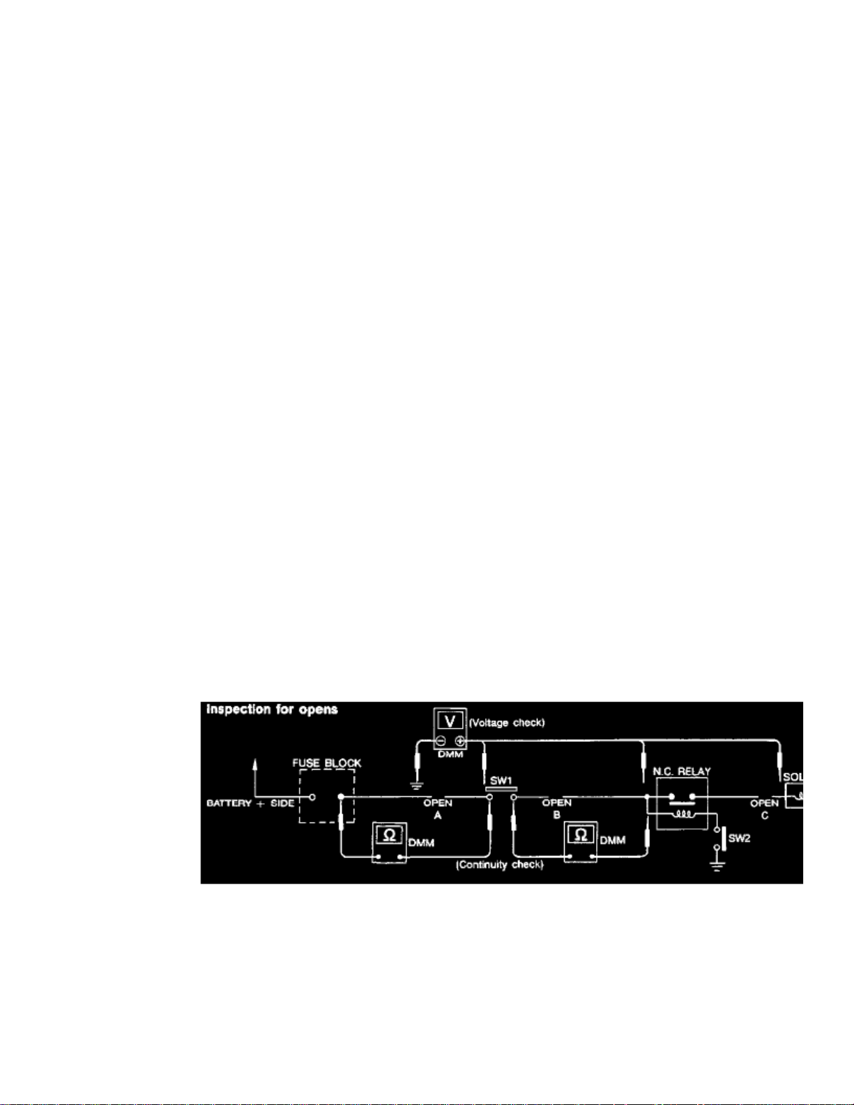
Continuity Check Method
The continuity check is used to find an open in the circuit. The Digital Multimeter (DMM) set on the resistance function will indicate an open circuit asover limit (no beep tone or no ohms symbol). Make sure to always start with the DMM at the highest resistance level.
To help in understanding the diagnosis of open circuits please refer to the schematic.
1. Disconnect the battery negative cable.2. Start at one end of the circuit and work your way to the other end. (At the fuse block in this example)3. Connect one probe of the DMM to the fuse block terminal on the load side.4. Connect the other probe to the fuse block (power) side of SW1.
Little or no resistance will indicate that portion of the circuit has good continuity.If there were an open in the circuit the DMM would indicate an over limit or infinite resistance condition. (point A)
Page 77

> Relays and Modules > Relays and Modules - Instrument Panel > Instrument Panel Control Module > Component Information > Diagrams > Diagram Information and
Instructions > Page 70
Xterra SE 2WD V6-3.3L (VG33E) (2002)
5. Connect the probes between SW1 and the relay.
Little or no resistance will indicate that portion of the circuit has good continuity.If there were an open in the circuit the DMM would indicate an over limit or infinite resistance condition. (point B)
6. Connect the probes between the relay and the solenoid.
Little or no resistance will indicate that portion of the circuit has good continuity.If there were an open in the circuit the DMM would indicate an over limit or infinite resistance condition. (point C)
Any circuit can be diagnosed using the approach in the above example.
Page 78
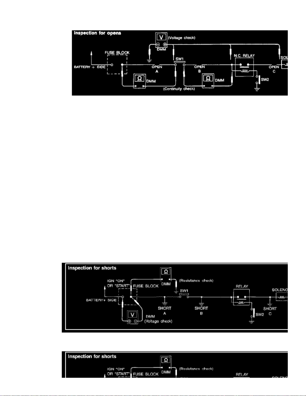
Voltage Check Method
To help in understanding the diagnosis of open circuits please refer to the schematic.
In any powered circuit an open can be found by methodically checking the system for the presence of voltage. This is done by switching the DMM to thevoltage function.
1. Connect one probe of the DMM to a known good ground.2. Begin probing at one end of the circuit and work your way to the other end.3. With SW1 open probe at SW1 to check for voltage.
Voltage:
Open is further down the circuit than SW1.
No Voltage:
Open is between fuse block and SW1 (point A).
4. Close SW1 and probe at relay.
Voltage:
Open is further down the circuit than the relay.
No Voltage:
Open is between SW1 and relay (point B).
5. Close the relay and probe at the solenoid.
Voltage:
Open is further down the circuit than the solenoid.
No Voltage:
Open is between relay and solenoid (point C).
Any powered circuit can be diagnosed using the approach in the above example.
Testing For "Shorts" In the Circuit
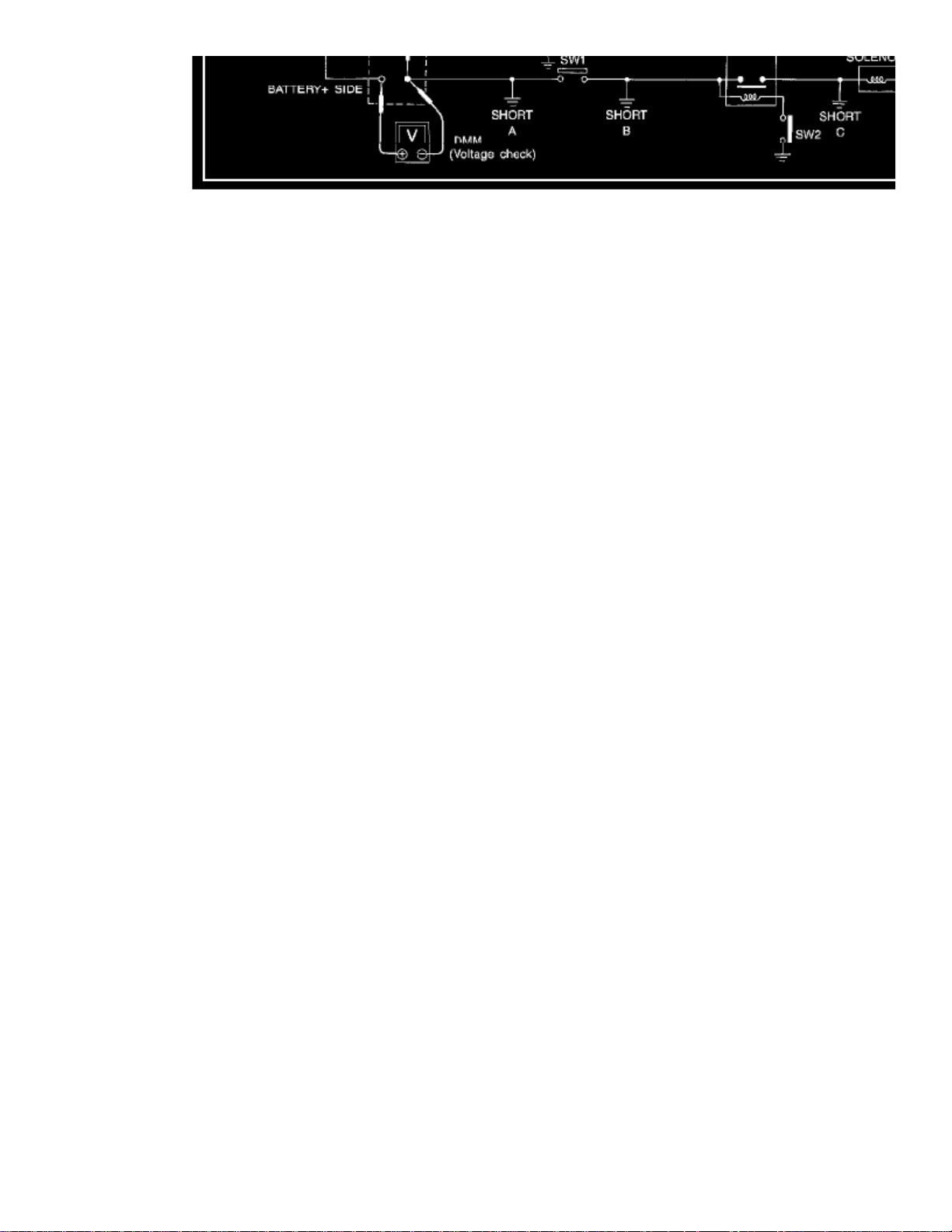
TESTING FOR "SHORTS" IN THE CIRCUIT
Page 79
> Relays and Modules > Relays and Modules - Instrument Panel > Instrument Panel Control Module > Component Information > Diagrams > Diagram Information and
Instructions > Page 71
Xterra SE 2WD V6-3.3L (VG33E) (2002)
Resistance Check Method
1. Disconnect the battery negative cable and remove the blown fuse.2. Disconnect all loads (SW1 open relay disconnected and solenoid disconnected) powered through the fuse.
Page 80
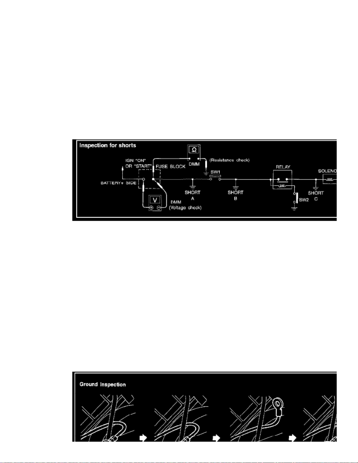
3. Connect one probe of the ohmmeter to the load side of the fuse terminal. Connect the other probe to a known good ground.4. With SW1 open check for continuity.
Continuity:
Short is between fuse terminal and SW1 (point A).
No Continuity:
Short is further down the circuit than SW1.
5. Close SW1 and disconnect the relay. Put probes at the load side of fuse terminal and a known good ground. Then check for continuity.
Continuity:
Short is between SW1 and the relay (point B).
No Continuity:
Short is further down the circuit than the relay.
6. Close SW1 and jump the relay contacts with jumper wire. Put probes at the load side of fuse terminal and a known good ground. Then check for
continuity.
Continuity:
Short is between relay and solenoid (point C).
No Continuity:
Check solenoid retrace steps.
Voltage Check Method
1. Remove the blown fuse and disconnect all loads (i.e. SW1 open relay disconnected and solenoid disconnected) powered through the fuse.2. Turn the ignition key to the ON or START position. Verify battery voltage at the battery + side of the fuse terminal (one lead on the battery +
terminal side of the fuse block and one lead on a known good ground).
3. With SW1 open and the DMM leads across both fuse terminals check for voltage.
Voltage:
Short is between fuse block and SW1 (point A).
No Voltage:
Short is further down the circuit than SW1.
4. With SW1 closed relay and solenoid disconnected and the
DMM leads across both fuse terminals check for voltage.
Voltage:
Short is between SW1 and the relay (point B).
No Voltage:
Short is further down the circuit than the relay.
5. With SW1 closed relay contacts jumped with fused jumper wire check for voltage.
Voltage:
Short is down the circuit of the relay or between the relay and the disconnected solenoid (point C).
No Voltage:
Retrace steps and check power to fuse block.
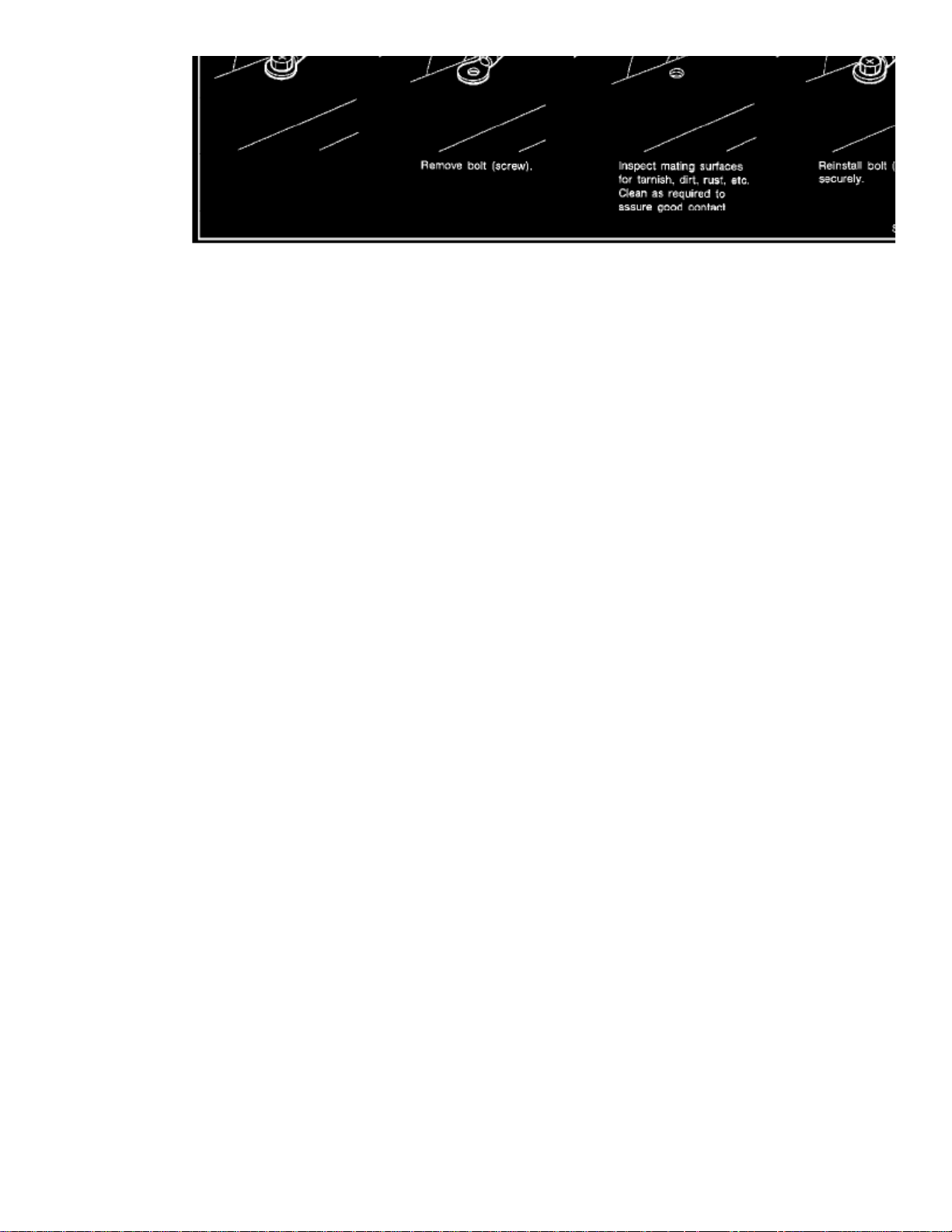
Ground Inspection
Page 81
> Relays and Modules > Relays and Modules - Instrument Panel > Instrument Panel Control Module > Component Information > Diagrams > Diagram Information and
Instructions > Page 72
Xterra SE 2WD V6-3.3L (VG33E) (2002)
Page 82
GROUND INSPECTION
Ground connections are very important to the proper operation of electrical and electronic circuits. Ground connections are often exposed to moisturedirt and other corrosive elements. The corrosion (rust) can become an unwanted resistance. This unwanted resistance can change the way a circuit works.
Electronically controlled circuits are very sensitive to proper grounding. A loose or corroded ground can drastically affect an electronically controlledcircuit. A poor or corroded ground can easily affect the circuit. Even when the ground connection looks clean there can be a thin film of rust on thesurface.
When inspecting a ground connection follow these rules:
1. Remove the ground bolt or screw.2. Inspect all mating surfaces for tarnish dirt rust etc.3. Clean as required to assure good contact.4. Reinstall bolt or screw securely.5. Inspect for "add-on" accessories which may be interfering with the ground circuit.6. If several wires are crimped into one ground eyelet terminal, check for proper crimps. Make sure all of the wires are clean, securely fastened and
providing a good ground path. If multiple wires are cased in one eyelet make sure no ground wires have excess wire insulation.
For detailed ground distribution information, refer to "GROUND DISTRIBUTION".
Voltage Drop Tests
VOLTAGE DROP TESTS
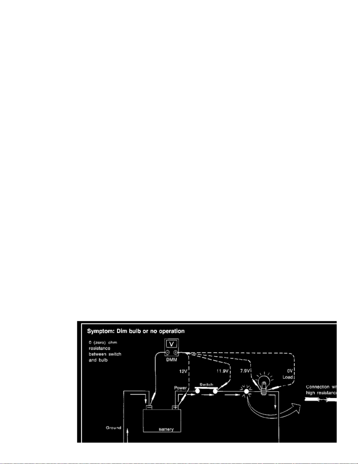
Voltage drop tests are often used to find components or circuits which have excessive resistance. A voltage drop in a circuit is caused by a resistancewhen the circuit is in operation.
0 ohms
Check the wire in the illustration. When measuring resistance with ohmmeter contact by a single strand of wire will give reading of . This wouldindicate a good circuit. When the circuit operates this single strand of wire is not able to carry the current. The single strand will have a high resistance tothe current. This will be picked up as a slight voltage drop.
Unwanted resistance can be caused by many situations as follows:
- Undersized wiring (single strand example)
- Corrosion on switch contacts
- Loose wire connections or splices.
If repairs are needed always use wire that is of the same or larger gauge.
Page 83

> Relays and Modules > Relays and Modules - Instrument Panel > Instrument Panel Control Module > Component Information > Diagrams > Diagram Information and
Instructions > Page 73
Xterra SE 2WD V6-3.3L (VG33E) (2002)
Measuring Voltage Drop - Accumulated Method
1. Connect the voltmeter across the connector or part of the circuit you want to check. The positive lead of the voltmeter should be closer to power
and the negative lead closer to ground.
2. Operate the circuit.3. The voltmeter will indicate how many volts are being used to push" current through that part of the circuit.
Note in the illustration that there is an excessive drop between the battery and the bulb.4.1 volt
Page 84
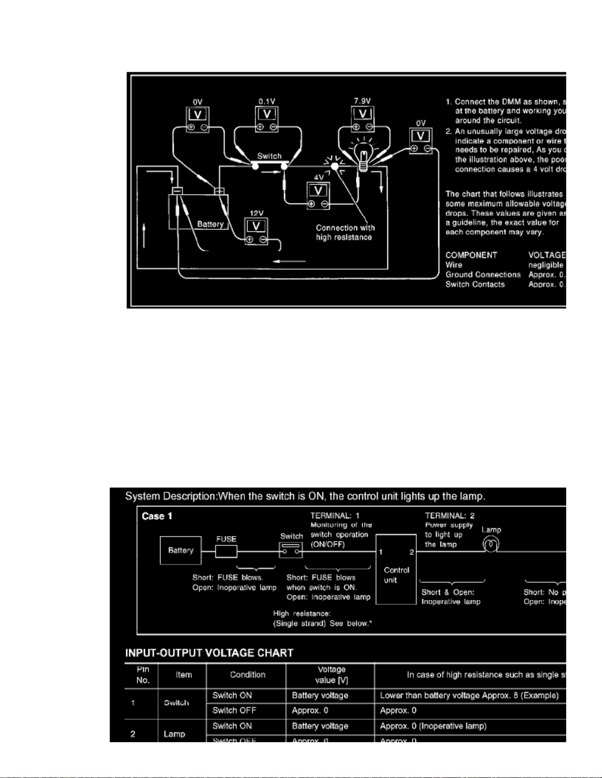
Measuring Voltage Drop - Step by Step
The step by step method is most useful for isolating excessive drops in low voltage systems (such as those in Computer Controlled Systems").
Circuits in the Computer Controlled System" operate on very low amperage.
The (Computer Controlled) system operations can be adversely affected by any variation in resistance in the system. Such resistance variation may becaused by poor connection improper installation improper wire gauge or corrosion.
The step by step voltage drop test can identify a component or wire with too much resistance.
Control Unit Circuit Test
Page 85

> Relays and Modules > Relays and Modules - Instrument Panel > Instrument Panel Control Module > Component Information > Diagrams > Diagram Information and
Instructions > Page 74
Xterra SE 2WD V6-3.3L (VG33E) (2002)
Control Unit Circuit Test Case 1
Page 86
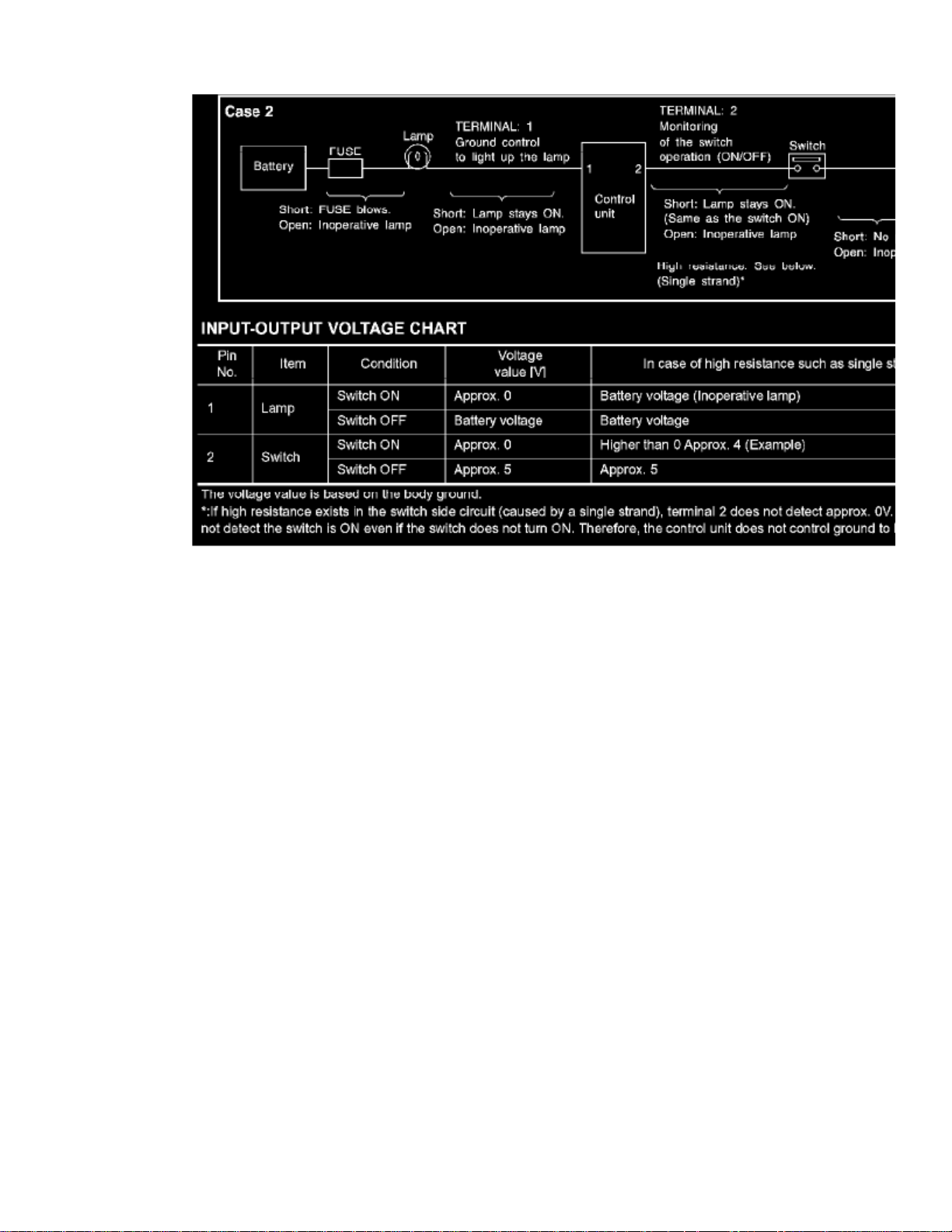
Control Unit Circuit Test Case 2
CONTROL UNIT CIRCUIT TEST
System Description:
When the switch is ON the control unit lights up the lamp.
Page 87

> Relays and Modules > Relays and Modules - Instrument Panel > Instrument Panel Control Module > Component Information > Diagrams > Diagram Information and
Instructions > Page 75
Xterra SE 2WD V6-3.3L (VG33E) (2002)
Page 88
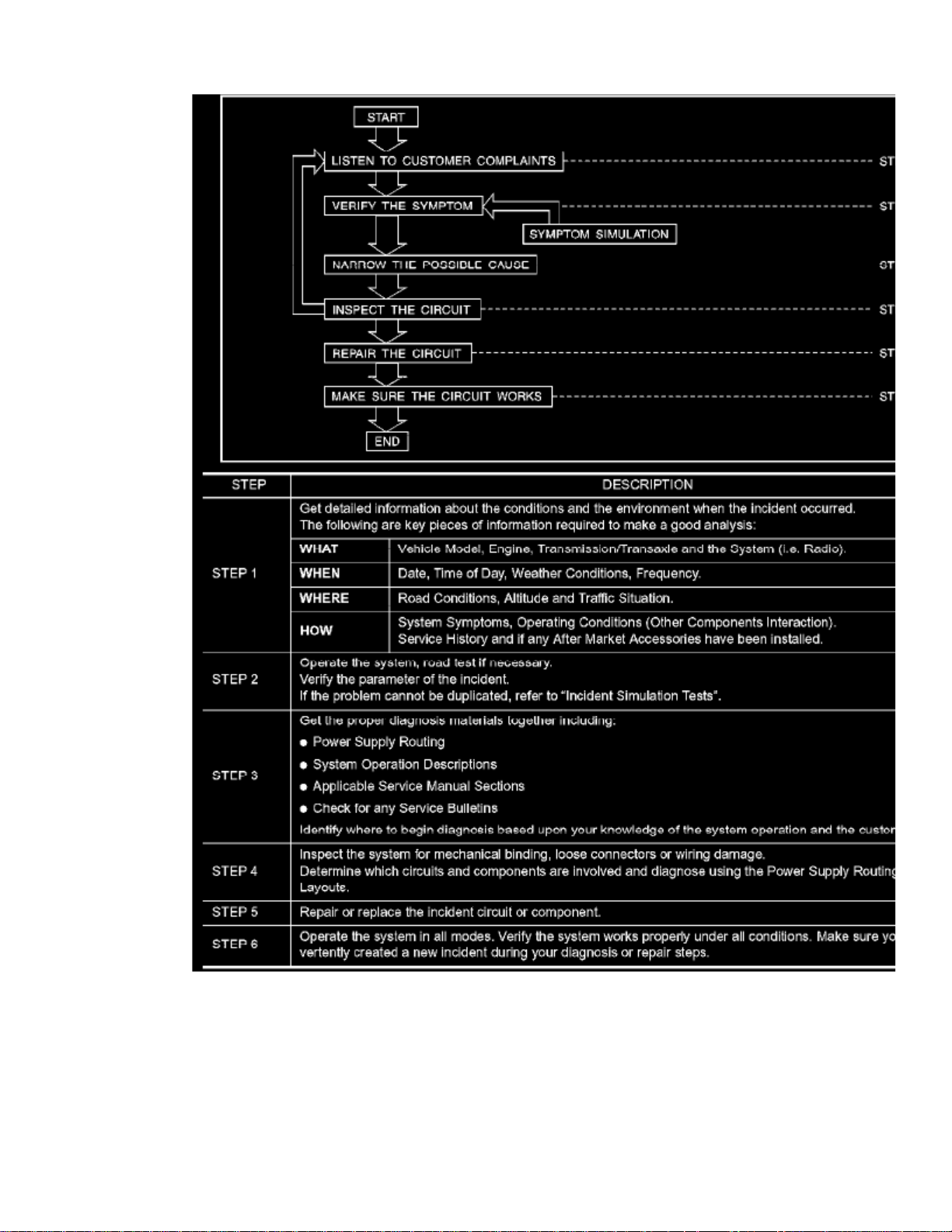
Work Flow
Cold or Hot Start Up
COLD OR HOT START UP
On some occasions an electrical incident may occur only when the car is started cold. Or it may occur when the car is restarted hot shortly after beingturned off. In these cases you may have to keep the car overnight to make a proper diagnosis.
Page 89

> Relays and Modules > Relays and Modules - Instrument Panel > Instrument Panel Control Module > Component Information > Diagrams > Diagram Information and
Instructions > Page 76
Xterra SE 2WD V6-3.3L (VG33E) (2002)
Electrical Load
Page 90
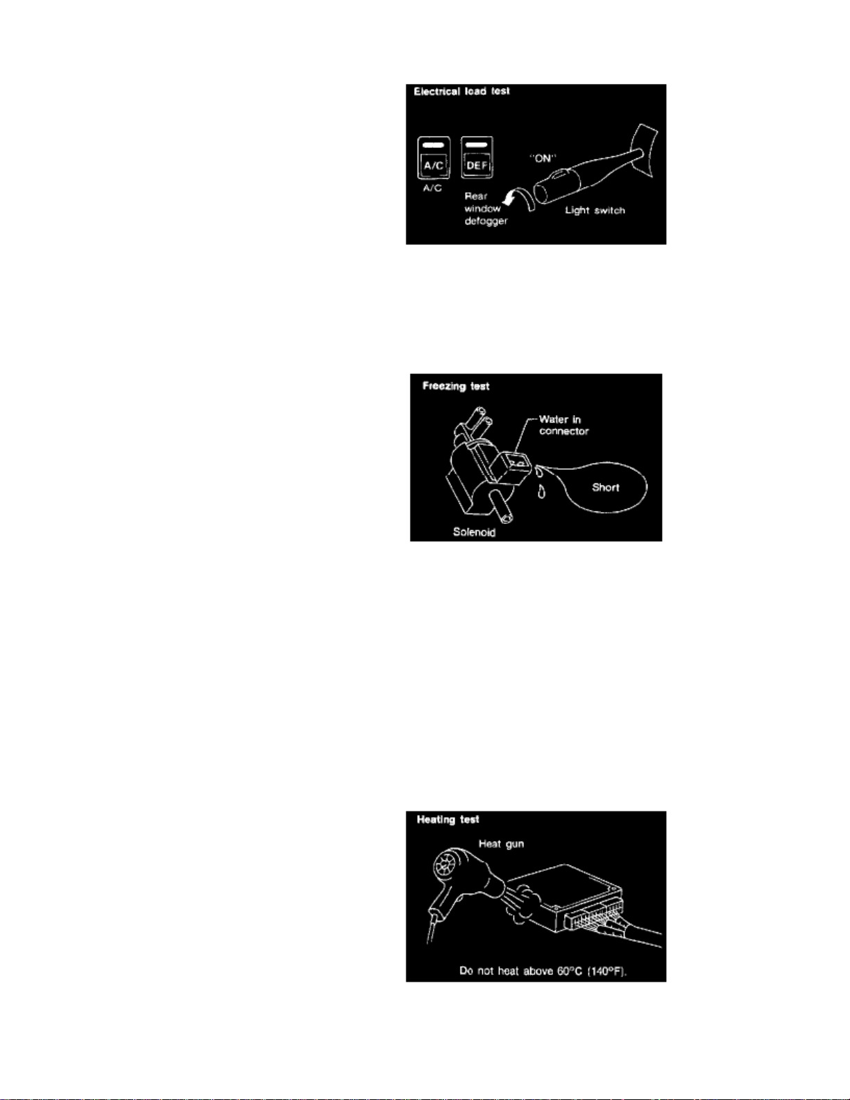
ELECTRICAL LOAD
The incident may be electrical load sensitive. Perform diagnosis with all accessories (including A/C rear window defogger radio fog lamps) turned on.
Freezing
FREEZING
The customer may indicate the incident goes away after the car warms up (wintertime). The cause could be related to water freezing somewhere in thewiring/electrical system.
The second method is to put the suspect component into a freezer long enough for any water to freeze. Reinstall the part into the car and check for thereoccurrence of the incident. If it occurs repair or replace the component.
Heat Sensitive
HEAT SENSITIVE
Page 91

> Relays and Modules > Relays and Modules - Instrument Panel > Instrument Panel Control Module > Component Information > Diagrams > Diagram Information and
Instructions > Page 77
Xterra SE 2WD V6-3.3L (VG33E) (2002)
There are two methods to check for this. The first is to arrange for the owner to leave the car overnight. Make sure it will get cold enough to demonstratethe complaint. Leave the car parked outside overnight. In the morning, do a quick and thorough diagnosis of those electrical components which could beaffected.
The owner's problem may occur during hot weather or after car has sat for a short time. In such cases you will want to check for a heat sensitivecondition.
To determine if an electrical component is heat sensitive, heat the component with a heat gun or equivalent.
Do not heat components above . If incident occurs while heating the unit, either replace or properly insulate the component.60 C (140 F)
Introduction
INTRODUCTION
Sometimes the symptom is not present when the vehicle is brought in for service. If possible, recreate the conditions present at the time of the incident.
Page 92
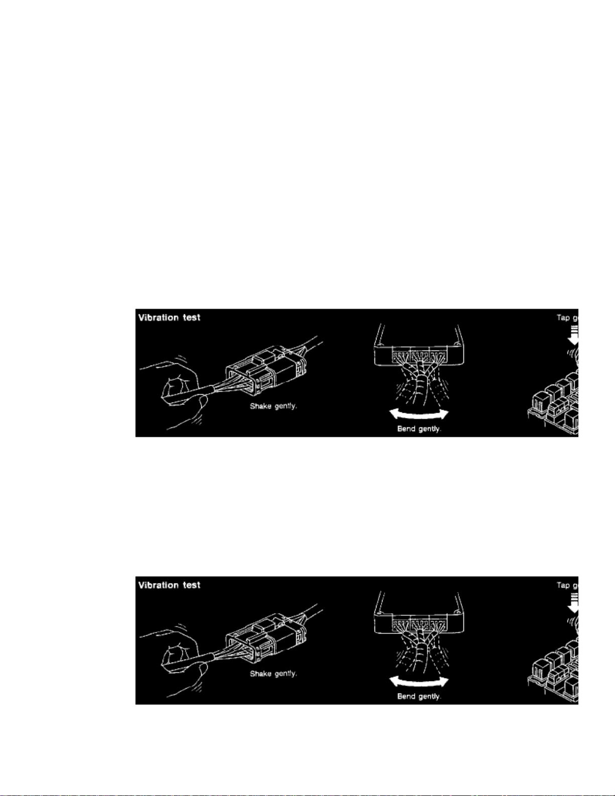
Doing so may help avoid a No Trouble Found Diagnosis. The following section illustrates ways to simulate the conditions/environment under which theowner experiences an electrical incident.
The section is broken into the six following topics:
- Vehicle vibration
- Heat sensitive
- Freezing
- Water intrusion
- Electrical load
- Cold or hot start up
Get a thorough description of the incident from the customer. It is important for simulating the conditions of the problem.
Vehicle Vibration
VEHICLE VIBRATION
The problem may occur or become worse while driving on a rough road or when the engine is vibrating (idle with A/C on). In such a case, you will wantto check for a vibration-related condition.
Connectors & Harness
HINT:
Connectors can be exposed to moisture. It is possible to get a thin film of corrosion on the connector terminals. A visual inspection may notreveal this without disconnecting the connector. If the problem occurs intermittently, perhaps the problem is caused by corrosion. It is a goodidea to disconnect, inspect and clean the terminals on related connectors in the system.
Sensors & Relays
Page 93

> Relays and Modules > Relays and Modules - Instrument Panel > Instrument Panel Control Module > Component Information > Diagrams > Diagram Information and
Instructions > Page 78
Xterra SE 2WD V6-3.3L (VG33E) (2002)
Determine which connectors and wiring harness would affect the electrical system you are inspecting.Gently shake each connector and harness while monitoring the system for the incident you are trying to duplicate. This test may indicate a loose or poorelectrical connection.
Gently apply a slight vibration to sensors and relays in the system you are inspecting.This test may indicate a loose or poorly mounted sensor or relay.
Engine Compartment
There are several reasons a vehicle or engine vibration could cause an electrical complaint. Some of the things to check forare:
- Connectors not fully seated.
- Wiring harness not long enough and is being stressed due to engine vibrations or rocking.
- Wires laying across brackets or moving components.
- Loose, dirty or corroded ground wires.
- Wires routed too close to hot components.
Page 94
To inspect components under the hood, start by verifying the integrity of ground connections.
First check that the system is properly grounded. Then, check for loose connection by gently shaking the wiring or components as previously explained.Using the wiring diagrams, inspect the wiring for continuity.
Behind the instrument panel
An improperly routed or improperly clamped harness can become pinched during accessory installation. Vehicle vibration can aggravate a harness whichis routed along a bracket or near a screw.
Under seating areas
An unclamped or loose harness can cause wiring to be pinched by seat components (such as slide guides) during vehicle vibration. If the wiring runsunder seating areas, inspect wire routing for possible damage or pinching.
Water Intrusion
WATER INTRUSION
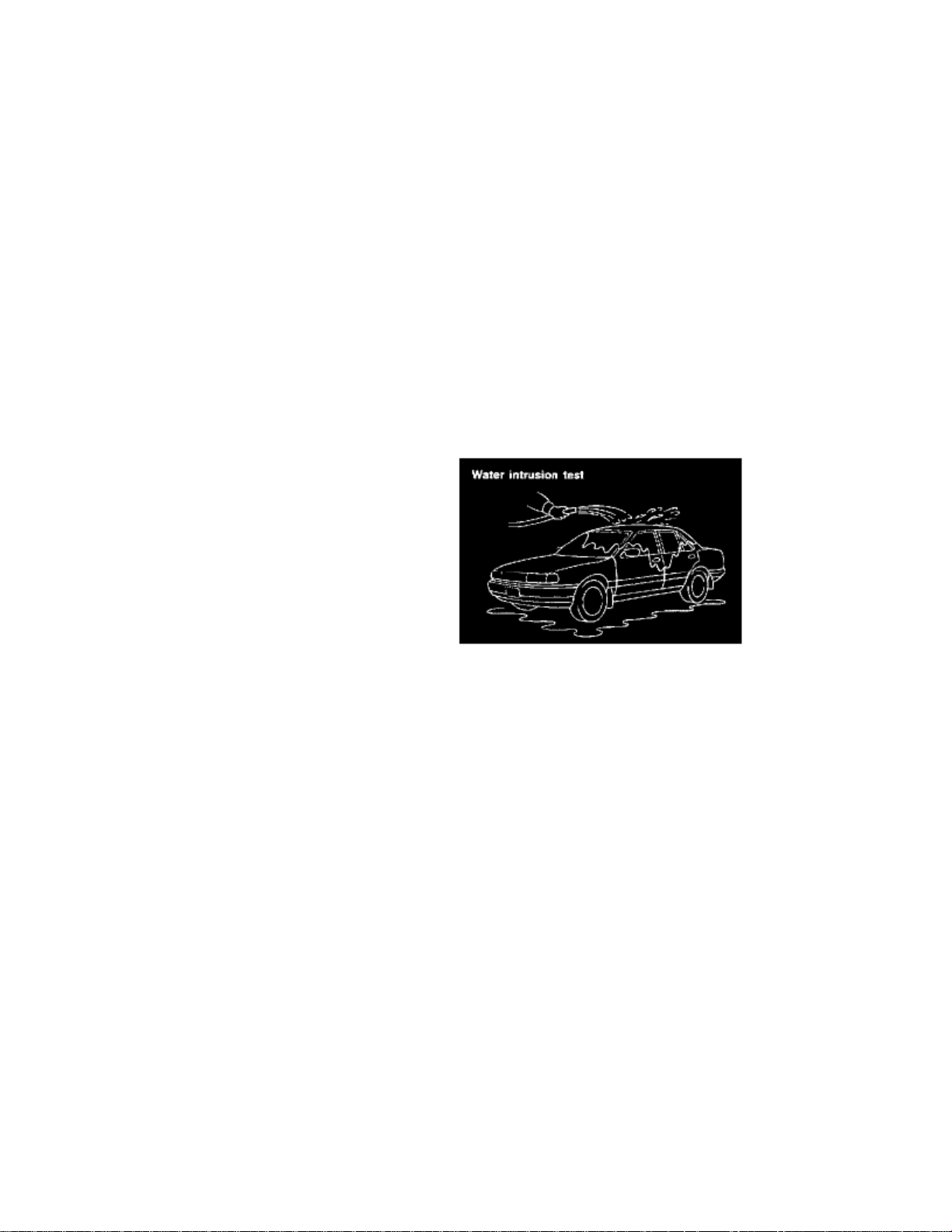
The incident may occur only during high humidity or in rainy/snowy weather. In such cases the incident could be caused by water intrusion on anelectrical part. This can be simulated by soaking the car or running it through a car wash.Do not spray water directly on any electrical components.
CONSULT-II Checking System
Page 95

> Relays and Modules > Relays and Modules - Instrument Panel > Instrument Panel Control Module > Component Information > Diagrams > Diagram Information and
Instructions > Page 79
Xterra SE 2WD V6-3.3L (VG33E) (2002)
Page 96
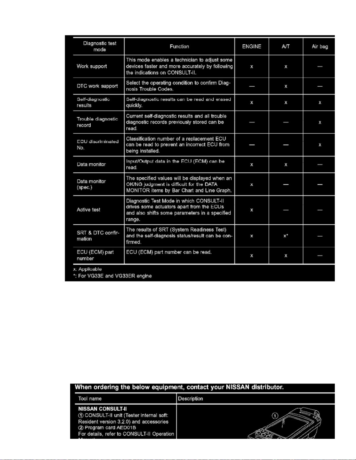
Function And System Application
Function and System Application
Nickel Metal Hydride Battery Replacement
CONSULT-II contains a Nickel Metal Hydride battery. When replacing the battery obey the following:
WARNING: Replace the Nickel Metal Hydride battery with Genuine CONSULT-II battery only. Use of another battery may present a risk offire or explosion. The battery may present a fire or chemical burn hazard if mistreated. Do not recharge, disassemble of dispose of in fire. Keep the battery out of reach of children and discard used battery conforming to the local regulations.
Page 97
> Relays and Modules > Relays and Modules - Instrument Panel > Instrument Panel Control Module > Component Information > Diagrams > Diagram Information and
Instructions > Page 80
Xterra SE 2WD V6-3.3L (VG33E) (2002)
Checking Equipment
Page 98
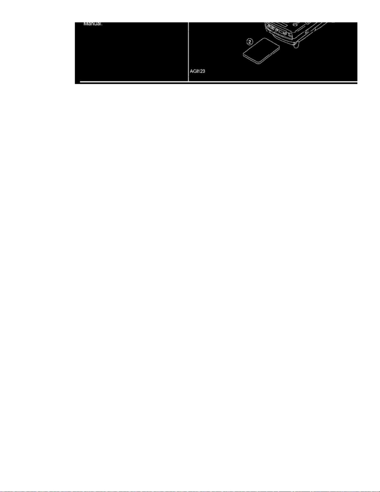
Loading Procedure
NOTE:
- The CONSULT-II must be used in conjunction with a program card. CONSULT-II does not require loading (Initialization) procedure.
- Be sure the CONSULT-II is turned off before installing or removing a program card.
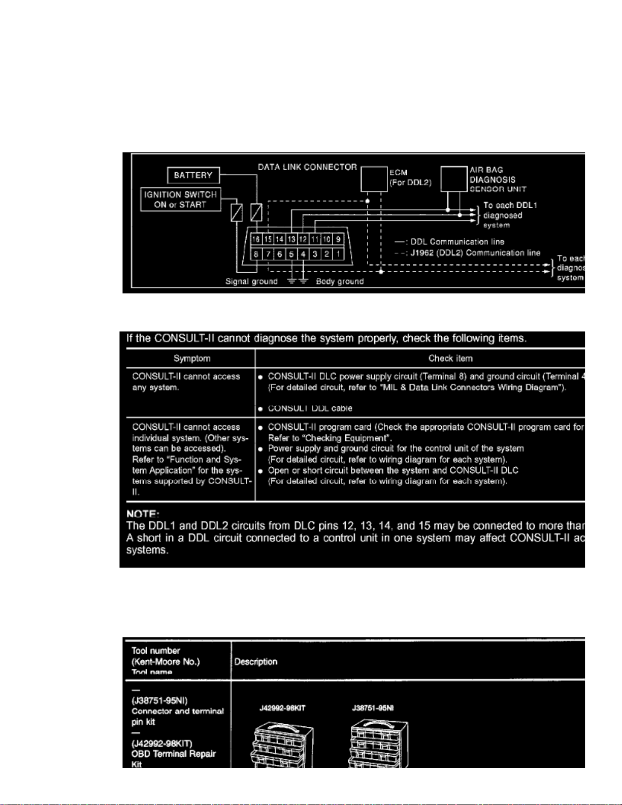
Consult-II Data Link Connector (DLC) Circuit
Inspection Procedure
How to Check Terminals
Page 99
> Relays and Modules > Relays and Modules - Instrument Panel > Instrument Panel Control Module > Component Information > Diagrams > Diagram Information and
Instructions > Page 81
Xterra SE 2WD V6-3.3L (VG33E) (2002)
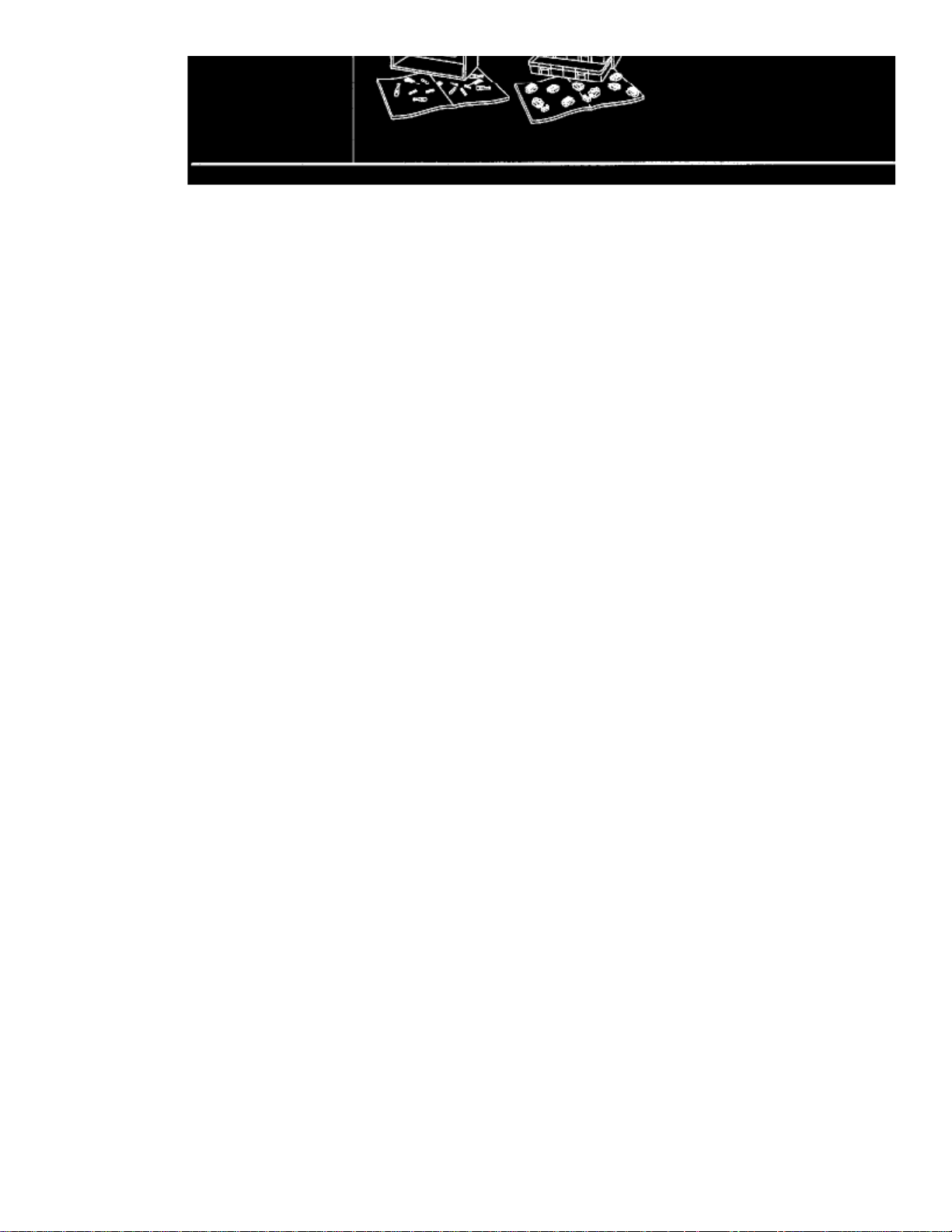
Connector and Terminal Pin Kit
Use the connector and terminal pin kit listed below when replacing connectors or terminals.
Page 100
The connector and terminal pin kit contains some of the most commonly used NISSAN connectors and terminals.
How to Probe Connectors
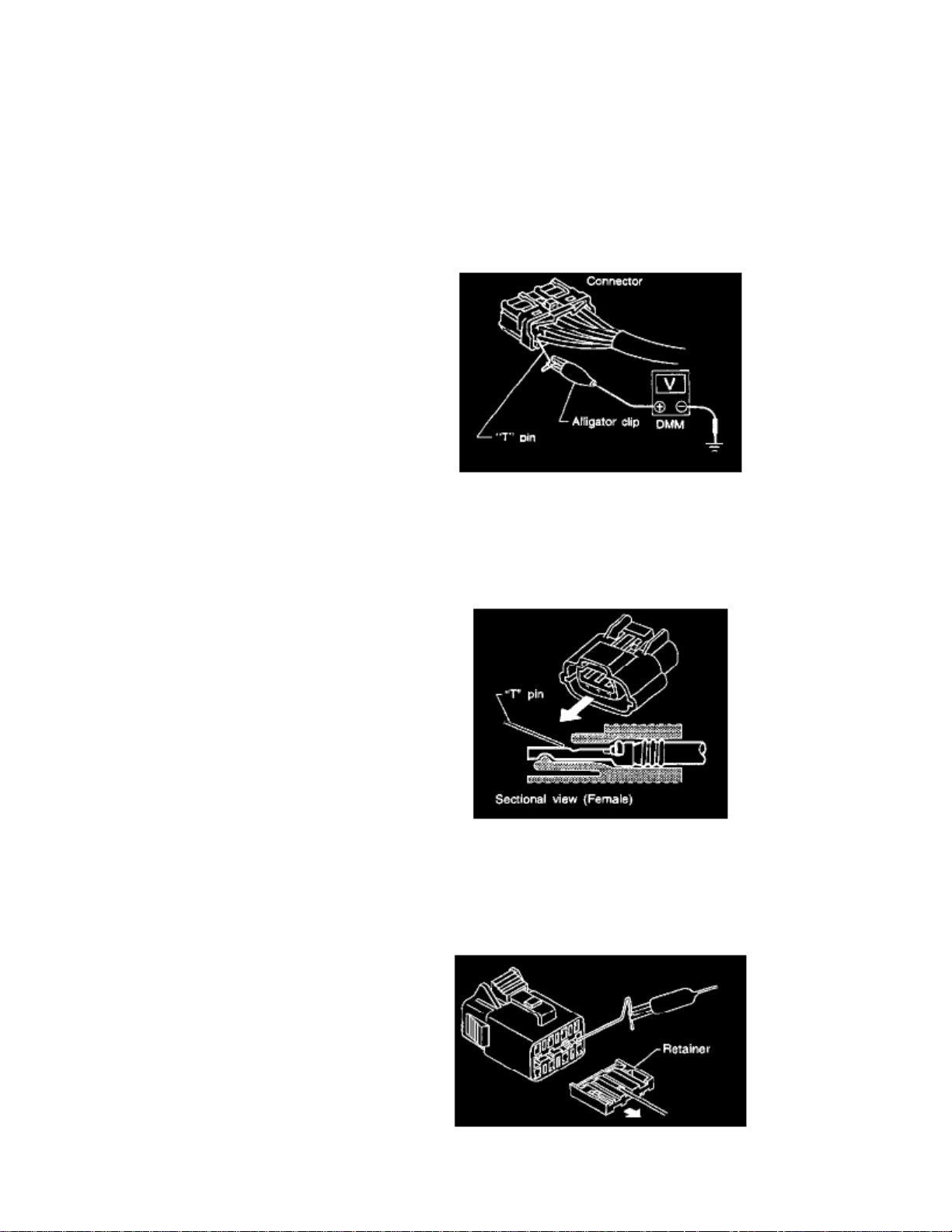
Connector damage and an intermittent connection can result from improperly probing of the connector during circuit checks.The probe of a digital multimeter (DMM) may not correctly fit the connector cavity. To correctly probe the connector, follow the procedures belowusing a "T" pin. For the best contact grasp the "T" pin using an alligator clip.
PROBING FROM HARNESS SIDE
Standard type (not waterproof type) connector should be probed from harness side with "T" pin.
- If the connector has a rear cover such as an ECM connector, remove the rear cover before probing the terminal.
- Do not probe waterproof connector from harness side. Damage to the seal between wire and connector may result.
PROBING FROM TERMINAL SIDE
Female Terminal
There is a small notch above each female terminal. Probe each terminal with the "T" pin through the notch. Do not insert any object other than thesame type male terminal into female terminal.
 Loading...