

Page 1
MICROMATIC 14E
Parts list
cod.08603315(2)00-02
Form Number 56042316
Page 2
00/02 F.Nr 56042316
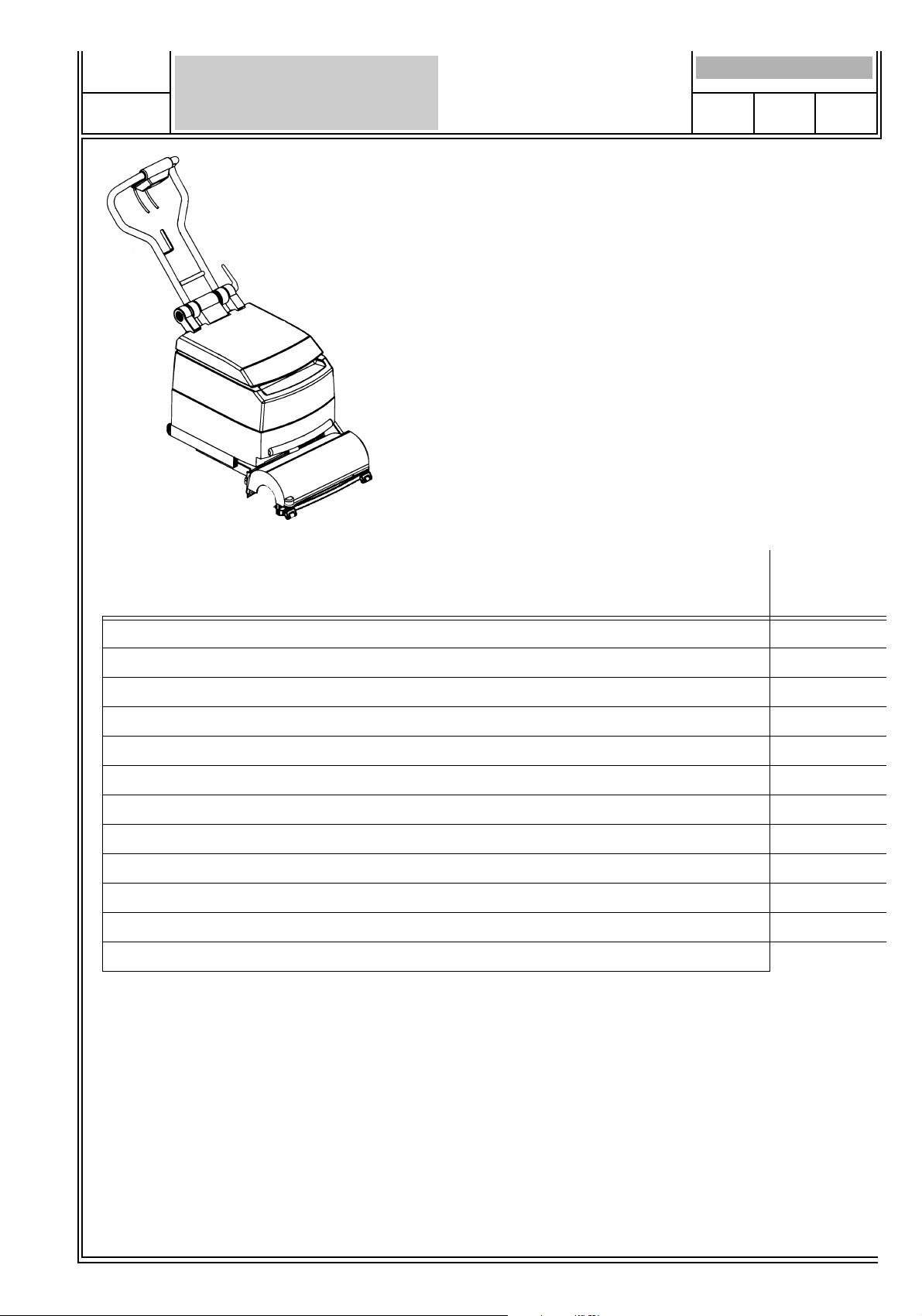
TABLE OF CONTENTS
MICROMATIC 14E
PAGE
1
CHASSIS SYSTEM
TWO TANK VERSION
SOLUTION SYSTEM
BRUSH DRIVE SYSTEM
SQUEEGEE ASSEMBLY
VACUUM SYSTEM
FRAME SYSTEM
HANDLE BAR
WIRING SYSTEM 220V-60HZ
WIRING DIAGRAM 120V-60Hz
WIRING SYSTEM 230V-50HZ
WIRING DIAGRAM 120V-50Hz
GB
Page
Seite
Page
2-3
4-5
6-7
8-9
10-11
12-13
14-15
16-17
18-19
20
21-22
23
= IDENTIFICATION OF NEW ITEM NUMBERS
WHEN ORDERING PARTS
- Use the 8 digit numbers from the “Part No.” columns in this parts list.
- Specify the model and serial number of the machine
- Use the space before to record the model and serial number for future reference.
MODEL
___________________________________
SERIAL No.
_________________________________
Page 3
PAGE
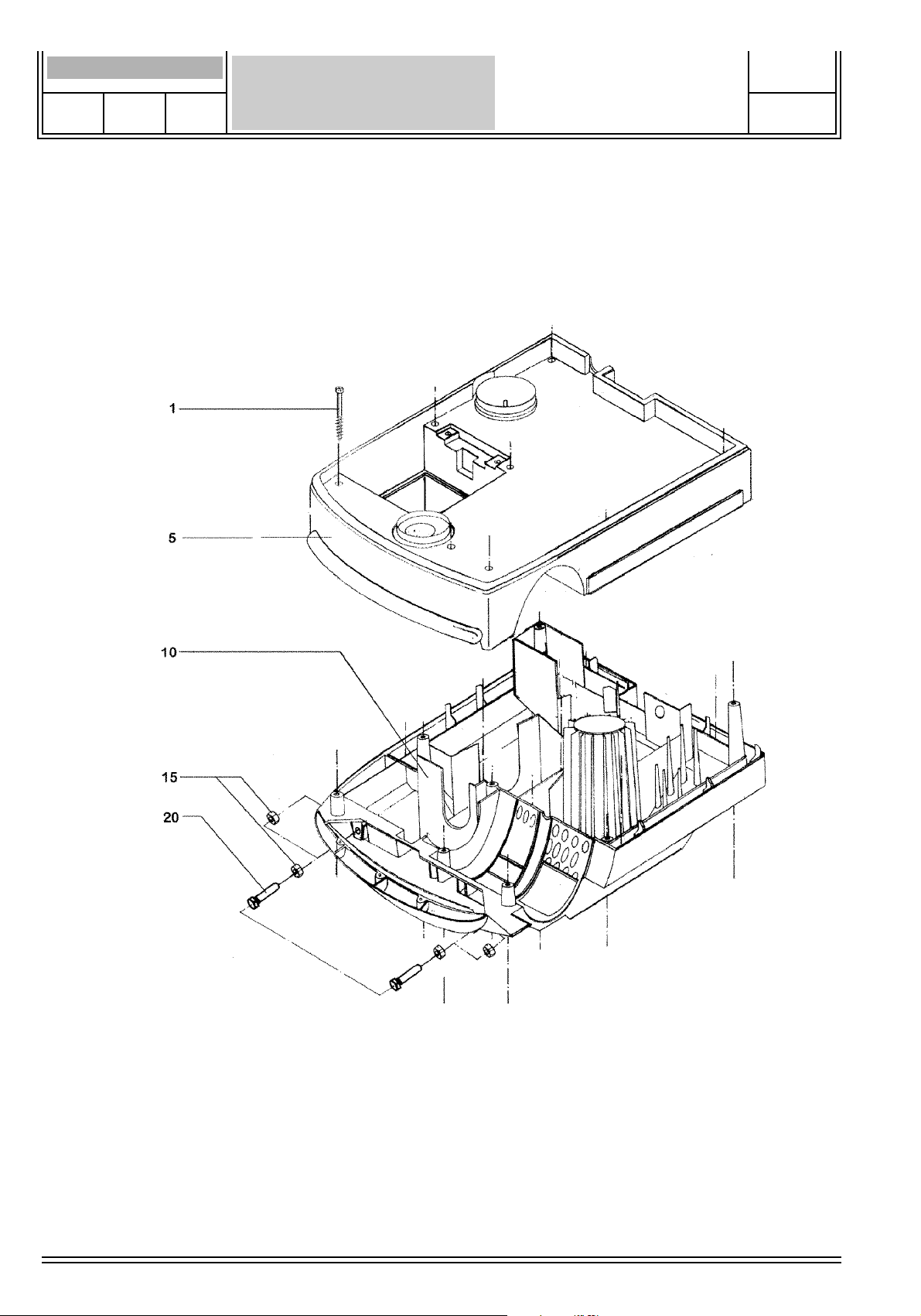
CHASSIS SYSTEM
MICROMATIC 14E
00/02 F.Nr 56042316
2
Page 4

00/02 F.Nr 56042316
Item Ref.No. Qty. Description
1 340246 8 Screw
5 340124 1 Top chassis
10 340245 1 Bottom chassis
15 003352 4 Hexagonal nut
20 003353 2 Hexagonal head screw
CHASSIS SYSTEM
MICROMATIC 14E
PAGE
3
Page 5
PAGE
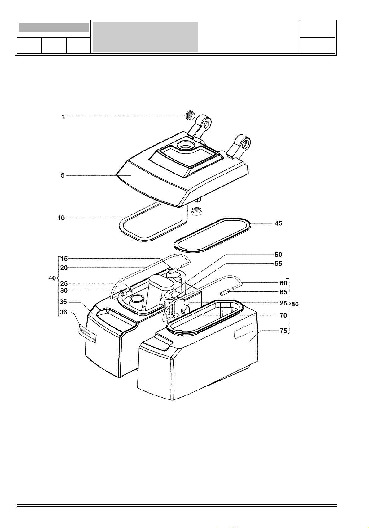
TWO-TANK VERSION
MICROMATIC 14E
00/02 F.Nr 56042316
4
Page 6
00/02 F.Nr 56042316
Item Ref.No. Qty. Description
1 340036
#5 603084
10 340038
15 340039 1
20 340040 1
25 340052 4
30 340244 1
35 340042 1
36 016333 1
40 340043 1
45 340044 1
50 340050 1
55 340051 1
60 340045 1
65 340047 1
70 340244 1
75 340048 1
76 015932 1
80 340049 1
TWO-TANK VERSION
1 Plug
1 Lid
1 Seal, recovery tank
Sleeve, long 32mm
Grip, recovery tank
Sprocket washer
Sleeve, short 14mm
Recovery tank
Foil
Recovery tank cpl
Seal, solution tank
Ball,float
Cage, float
Grip, solution tank
Sleeve, long 19mm
Sleeve, short 14mm
Solution tank
Foil
Solution tank cpl
MICROMATIC 14E
PAGE
5
Page 7
PAGE
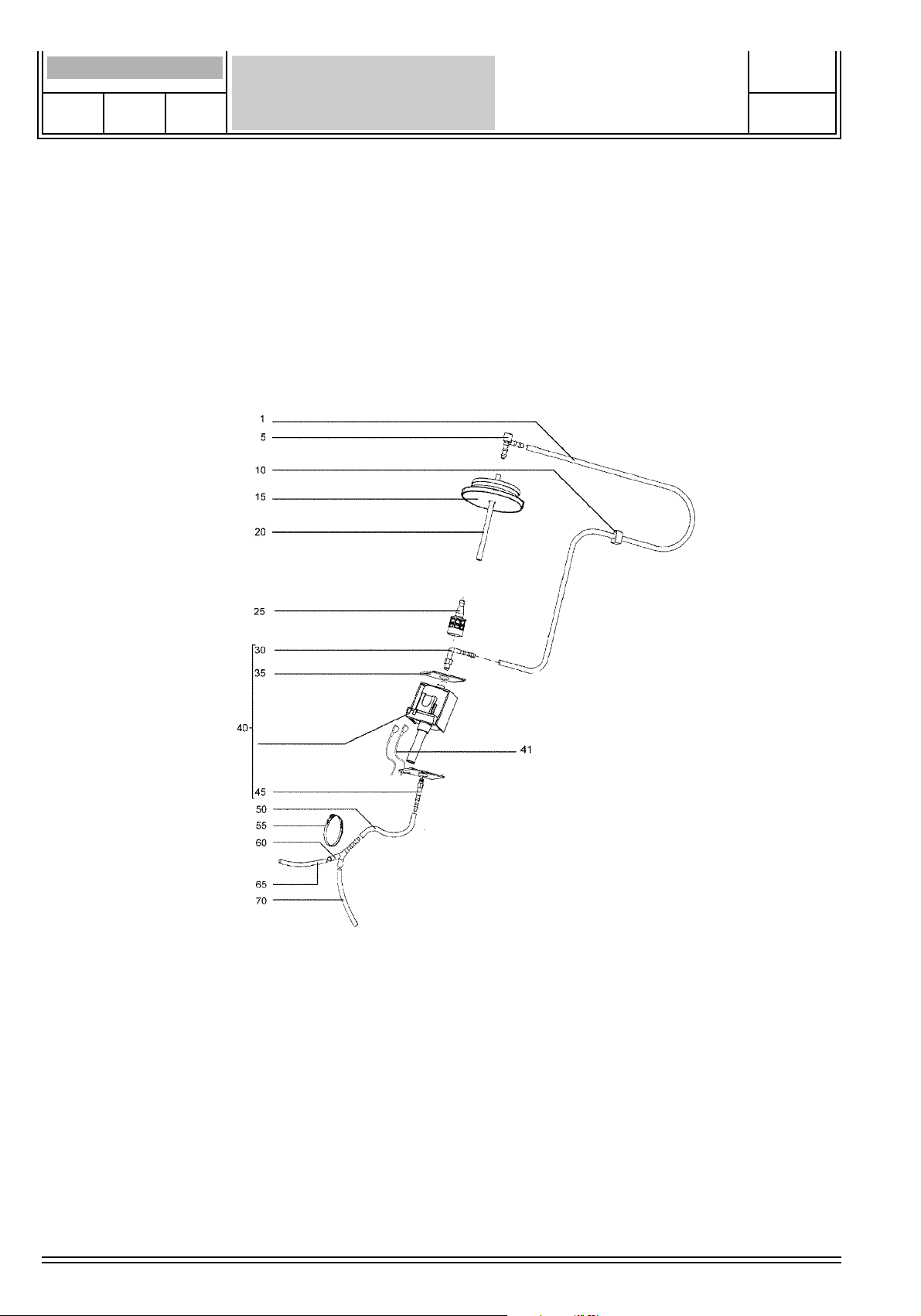
SOLUTION SYSTEM
MICROMATIC 14E
00/02 F.Nr 56042316
6
Page 8
00/02 F.Nr 56042316
Item Ref.No. Qty. Description
1 340243 1 Hose, PVC
5 340177 1 L-connection
10 340178 1 Rubber socket
15 340179 1 Plug with hole
20 340180 1 Hose
25 340181 1 Filter
30 340242 1 L-connection
35 340191 2 Insulation
40* 340554 1 Pump-C.E.M.E- 120V/ 60+50Hz cpl.
40 340555 1 Pump-C.E.M.E- 230V/50Hz
41 340556 2 Strand wire
45 340239 1 Tube
50 340185 1 Hose
55 340187 1 Clamp
60 340186 1 Y-piece
65 340188 1 Hose
70 340191 1 Hose
SOLUTION SYSTEM
MICROMATIC 14E
PAGE
7
*Pump, cpl.
Pump C.E.M.E. Part. No. 340241
L-connection Part. No. 340242
Insulation board Part. No. 340191
Tube Part. No. 340239
Resistor cpl. 33 Ohm Part. No. 340220 see page 21 Item 95
Page 9

PAGE
BRUSH DRIVE SYSTEM
MICROMATIC 14E
00/02 F.Nr 56042316
8
Page 10

00/02 F.Nr 56042316
Item Ref.No. Qty. Description
1 340152 1 Brush motor 120V / 50+60 Hz
1 340309 1 Brush motor 220-240V / 50+60 Hz
5 340153 2 Rubber Band
10 340166 1 Washer
15 340167 1 Motor pulley
20 340154 1 Rubber band
25 003365 4 Scr, Soc Hd M5x16
30 340168 1 Motor cover, top
35 003364 4 Hexagonal nut M5
40 340169 1 Motor cover, bottom
41 340151 1 Motor cover, cpl.
45 340557 1 Gear case
50 340171 4 Insulation covering
55 340172 1 Motor flange
60 340173 4 Insulation covering
65 003366 4 Washer, Flt 5.3
70 340237 4 Screw
75 003347 4 Washer, Flt 6.2
80 003368 4 Screw
85 340175 1 Drive belt
90 340236 1 Gear cover
95 003365 6 Screw
100 340156 1 Wing bolt cpl.
105 003347 1 Locking ring
110 340157 2 Rubber disc
115 340158 1 Compression ring
120 340150 1 O-Ring
125 340159 1 Locking washer
130 340160 1 Shaft
135 340161 1 Shaft seal
140 340162 2 Locking ring
145 340163 2 Ball bearing
150 340164 1 Distance sleeve
155 340165 1 Pulley drive shaft
- 340128 1 Brush, nylon, (STD)
- 340552 1 Brush, nylon, carbide 500 (OPT)
- 340551 1 Brush, nylon, carbide 320 (OPT)
BRUSH DRIVE SYSTEM
MICROMATIC 14E
PAGE
9
Page 11

PAGE
10
SQUEEGEE ASSEMBLY
MICROMATIC 14E
00/02 F.Nr 56042316
Page 12

00/02 F.Nr 56042316
Item Ref.No. Qty. Description
1 340060 1 Cover, suction cannal cannal
5 340061 2 Bumper roller
10 340062 2 Screw
15 340064 2 Seal, squeegee housing
20 340211 1 Squeegee housing
25 340210 2 Wheel
30 340558 2 Bolt
35 003385 4 Screw
40 340063 2 Retaining strip
45 340066 2 Squeegee inside
50 340067 2 Squeegee outside
55 003369 8 Screw
60 340054 1 Tension spring
65 340235 2 Screw
70 340559 2 Nozzle
75 340233 2 Seal
80 340070 1 Sleeve
85 003347 1 Washer
90 340074 1 Screw
95 340069 1 Linkage arm
100 340216 2 Screw
105 340232 1 Guide
110 340072 1 Bolt
#115 603728 1 Squeegee head
120 340067 1 Squeegee housing, rear
SQUEEGEE ASSEMBLY
MICROMATIC 14E
PAGE
11
Squeegee housing front cpl. 340094 08603362
Squeegee housing, rear cpl. 340075 08603361
Page 13

PAGE
12
VACUUM SYSTEM
MICROMATIC 14E
00/02 F.Nr 56042316
Page 14

00/02 F.Nr 56042316
Item Ref.No. Qty. Description
1 009236 2 Scr. Flt Phil Thd Form M5x20
5 340140 1 Strip
10 340141 1 Spring
15 340130 1 Filter cover
20 340131 1 Sound insulation, top
25 340132 1 Clamp collar
30 340133 1 Exhaust sound insulation Schall
35 340134 2 Hose clamp
40 340135 1 Suction hose
55 340137 1 Exhaust
60 340138 1 Hose clamp
65 340139 1 Bottom insulation
67 340142 1 Pre-filter, turbine
68 340143 1 Suction grate
70 340144 1 Seal, turbine inlet
75 340145 1 Seal, recovery tank inlet
80 340136 1 Seal
83 340231 1 Strand wire
85 340146 1 Turbine-120V/60Hz
85 340230 1 Turbine-220-240V/50+60Hz
90 340229 1 Seal
95 340148 1 Pre-filter, motor
VACUUM SYSTEM
MICROMATIC 14E
PAGE
13
Page 15

PAGE
14
FRAME SYSTEM
MICROMATIC 14E
00/02 F.Nr 56042316
Page 16

00/02 F.Nr 56042316
Item Ref.No. Qty. Description
1 340104 1 Frame
5 340105 2 Plug
6 014828 1 Decal
10 340106 2 Guide wheel
15 003359 2 Cheese head screw M10x22
20 340107 1 Spring
25 340227 1 Bolt
30 340109 4 Locking washer, lifting
35 340228 1 Pedal, lifting
40 340561 1 Bolt
45 340113 1 Spring
50 340114 2 Tension spring
55 340115 1 Shaft
60 340116 2 Wheel, front
65 340117 1 Lifting frame
70 003361 2 Screw Hex M8x35
75 003362 2 Washer Flt 8
80 340118 1 Compression spring
85 340119 1 Adjustment nut
90 340226 1 Hexagon head nut
95 340225 1 Pedal, lowering
100 340122 2 Sleeve
105 003362 2 Washer
110 003363 2 Cheese head screw M8x20
115 340224 4 Screw
FRAME SYSTEM
MICROMATIC 14E
PAGE
15
Page 17

PAGE
16
HANDLE BAR
MICROMATIC 14E
00/02 F.Nr 56042316
Page 18

00/02 F.Nr 56042316
Item Ref.No. Qty. Description
1 015931 1 Decal Display
5 340076 1 Housing with foil cpl.
10 003354 2 Screw
15 340077 1 Switch housing , rear
20 003356 8 Screw Pan Phil M3.5x16
25 340078 1 Handle bar
26 340079 1 Cable release
30 009233 1 Nut, Hex Prevaling Torq M12
35 340082 1 Distance sleeve
40 340080 1 Housing
45 003355 2 Screw Pan Phil M6x45
50 003347 4 Washer Flt 6.4
55 009234 2 Hex, Cap Nut M6
60 340086 1 Shaft
65 340091 1 Distance sleeve
70 340092 1 Pressure plate
75 009235 1 Locking nut
85 340088 1 Lever
90 003358 1 Screw Hex M6x25
100 340083 2 Clamp
105 340090 1 Ratchet disc
110 003357 4 Cheese head screw M6x12
115 340084 1 Compression spring
120 340085 1 Ratchet disc
125 340087 1 Key
HANDLE BAR
MICROMATIC 14E
PAGE
17
Page 19

PAGE
18
WIRING SYSTEM 120V 60Hz
(grounded)
MICROMATIC 14E
00/02 F.Nr 56042316
Page 20

00/02 F.Nr 56042316
WIRING SYSTEM 120V 60Hz
MICROMATIC 14E
(grounded)
Item Ref.No. Qty. Description
1 340012 1 Protection cap
5 340013 1 Switch (pump)
10 340205 1 Socket
15 340206 1 Internal cable cpl.
20 340017 1 Capacitor 40µF
25 340018 1 Strand wire
30 340020 1 Cable clamp
40 340193 1 Strand wire
45 340192 1 Clamp
50 340194 1 Strand wire
55 340562 1 Cheese Hd screw M4x5
60 340199 2 Switch
65 340011 3 Protection cap
70 340195 3 Frame
75 340197 1 Switch
80 340198 1 Socket
85 340209 2 Socket
90 009228 1 Scr, Pan Phil Tread Form M2.9x16
95 340220 1 Resistor cpl. 33 Ohm / 25W (C.E.M.E Pump)
100 340207 1 Self-tapping screw
105 340196 1 Power supply cable cpl.
110 340234 1 Strand wire – yellow/green
115 340563 1 Cheese Hd Scr. M4x16
120 003345 1 Nut, Hex SS M4
PAGE
19
Page 21

PAGE
20
WIRING DIAGRAM 120V60HZ
MICROMATIC 14E
00/02 F.Nr 56042316
120V/60Hz
CC= CABLE CLAMP
S1= MAIN SWITCH
S2= VACUUM MOTOR SWITCH
S3= PUMP SWITCH
S4= SOLUTION DOSING SWITCH
C1= CABLE INTERNAL
PSC= POWER SUPPLY CORD
M1= BRUSH MOTOR WITH CIRCUIT BREAKER
M2= VACUUM MOTOR
M3= CEME PUMP
R= RESISTOR
C1= WORK CAPACITOR
C2= SUPPRESSION FILTER
Page 22

PAGE
21
WIRING SYSTEM 230V-50Hz
MICROMATIC 14E
00/02 F.Nr 56042316
Page 23

00/02 F.Nr 56042316
Item Ref.No. Qty. Description
1 340012 1 Protection cap
5 340013 1 Switch (pump)
10 340014 1 Strand wire
15 340016 2 Canble eye
20 340205 1 Socket
25 340564 1 Internal cable cpl.
30 340310 1 Capacitor 40µF
45 340020 1 Cable clamp
50 340199 2 Switch
55 340011 3 Protection cap
60 340195 3 Frame
65 340197 1 Switch
70 340311 1 Power supply cable cpl.
71 340198 1 Socket
75 340015 1 Strand wire, set
80 340209 2 Socket
85 009228 1 Scr, Pan Phil Tread Form M2.9x16
90 340018 1 Strand wire
95 340565 1 Resistor cpl. 25W - 270Ohm (C.E.M.E) Pump)
100 340207 1 Self-tapping screw
105 340566 1 0.1 µF Capacitor
WIRING SYSTEM 230V-50Hz
MICROMATIC 14E
PAGE
22
Page 24

PAGE
23
WIRING DIAGRAM 120V50HZ
MICROMATIC 14E
00/02 F.Nr 56042316
230V/50Hz
CC= CABLE CLAMP
S1= MAIN SWITCH
S2= VACUUM MOTOR SWITCH
S3= PUMP SWITCH
S4= SOLUTION DOSING SWITCH
C1= CABLE INTERNAL
PSC= POWER SUPPLY CORD
M1= BRUSH MOTOR WITH CIRCUIT BREAKER
M2= VACUUM MOTOR
M3= PUMP
R= RESISTOR
C1= WORK CAPACITOR
C2= SUPPRESSION FILTER
Page 25

Graphic project Visual Division Milan Italy
COD.08603315(2)00-02
Nilfisk-Advance Italia S.p.A.
Località Novella Terza
26862 Guardamiglio (Lo)
Tel.: +39 0377 414021
Fax: +39 0377 51443
 Loading...