

Page 1

C 100.7
C 105.7
C 110.7
C 120.7 - C 120.7 X-TRA
C 125.7 - C 125.7 X-TRA
Repair Manual ver. 1.1
Page 2

Index
A. Saftey precautions 3
B. Technical data 4-5
C. Construction 6-8
D. Service / Repair 9-18
E. Torque 18-20
F. Operating supplies 21
G. Operation 22-24
H. Diagram 25
2
Page 3

Safety precautions.
A
WARNING!
High pressure jets can be dangerous. Never direct the water jet at persons
pets, live electrical equipment or the machine self.
The operator and anyone in the immediate vicinity of the site of cleaning
should take action to protect themselves from being struck by debris dislodged during operation. Wear goggles during operation.
Never try to clean clothes or footwear on yourself or other persons.
Do not let children or people who have not read the instruction manual
operate the machine.
Never use the machine in an environment where there could be a danger of
explosion. If any doubt arises, please contact the local authorities.
It is not allowed to clean asbestos- containing surfaces with high pressure.
This high pressure washer must not be used at temperatures below 0°C.
Never let any persons stay under the product when stored on the wall.
3
Page 4

Technical Data.
Product segment: Consumer C100.7 C105.7
Specification
Voltage
Frequency
Power consumption A
Power absorbed KW
Numbers of revolutions
Water volume, HP l / min.
Pump pressure bar
Nozzle pressure bar
Opening pressure bar
Retaining time min.
Oil contents
Oil type
Max water inlet temperature
Max water inlet pressure bar
High pressure hose length m
Suction height m
Electric cable m
Insulation class
Tightness
bar
V
Hz
rpm./ min.
ml
ARTL 32 ARTL 32 ARTL 32
C 40 40 40
B B B
IPX5 IPX5 IPX5
Max 100 Max 105 Max 110
220-240 220-240 220-240
50-60 50-60 50-60
6 6 6
1,3 1,4 1,4
17.500-18.500 17.500-18.500 17.500-18.500
5,3 5,2 5,2
70 75 80
53-63 57-67 62-72
90-110 90-110 90-110
5 5 5
55 55
10 10 10
3m/5m Textile 5m Textile 5m Textile
0,5 0,5 0,5
5m 5m 5m
B
C110.7 /
C110.7 X-tra
55
4
Page 5

Technical Data.
Product segment: Consumer C120.7 / C120.7 X-tra C125.7 / C125.7 X-tra
Specification
Voltage
Frequency
Power consumption A
Power absorbed KW
Numbers of revolutions
Water volume, HP l / min.
Pump pressure bar
Nozzle pressure bar
Opening pressure bar
Retaining time min.
Oil contents
Oil type
Max water inlet temperature
Max water inlet pressure bar
High pressure hose length m
Suction height m
Electric cable m
Insulation class
Tightness
bar
V
Hz
rpm./ min.
ml 55 55
ARTL 32 ARTL 32
C 40 40
B B
IPX5 IPX5
Max 120 Max 125
220-240 220-240
50-60 50-60
6 6,5
1,4 1,5
16.500-17.500 16.000-17.000
5,2 5,4
85 95
66-76 75-85
110-130 110-130
5 5
10 10
6m Textile 6m Textile
0,5 0,5
5m 5m
B
5
Page 6
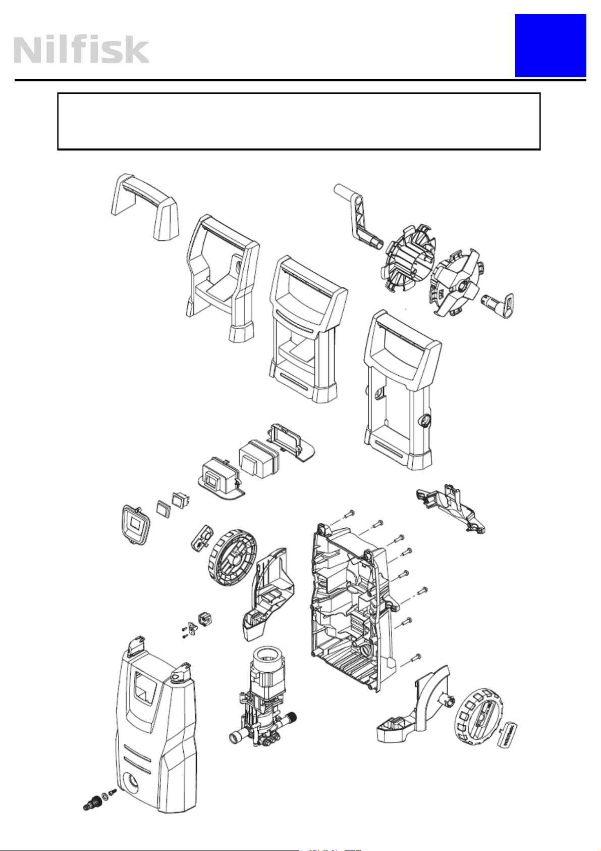
Construction.
C 100.7 - C 105.7 - C 110.7 C 120.7 - C 120.7 X-TRA
Construction of cabinet parts.
C
(!)
(!) Part 24, 25, 26 are on only used on PG versions
6
Page 7
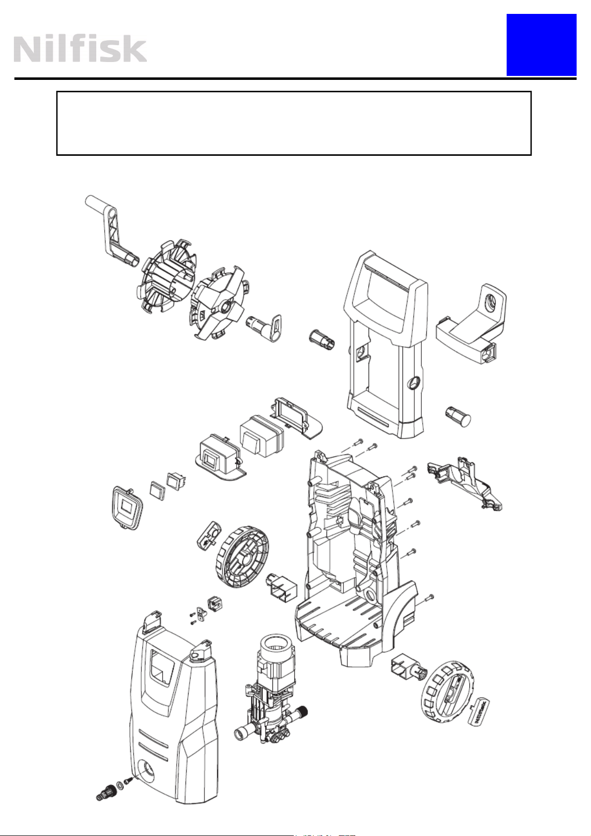
Construction.
C 125.7 - C 125.7 X-TRA
Construction of cabinet parts.
C
(!)
7
Page 8

Construction.
C 100.7 - C 105.7 - C 110.7
C 120.7 - C 120.7 X-TRA - C 125.7 - C 125.7 X-TRA
Construction of pump unit.
C
8
Page 9

Service / Repair.
D
Dismounting of cabinet rear part on following variants:
C 100.7 - C 105.7 - C 110.7 - C 120.7 - C 120.7 X-TRA
1. Tools: Screwdriver PH2
2. Remove the 2 screws (Long) fixing the handle
3. Remove the 6 screws (Short) from the rear side (fig. 3)
4. Don’t remove the accessory bracket and the wheels
5. The cabinet rear part can be removed and there is now access to the motor pump unit
Fig. 1
Fig. 2
Long screws
Short screws
9
Page 10

Service / Repair.
D
Dismounting of cabinet rear part on following variants:
C 125.7 - C 125.7 X-TRA
1. Tools: Screwdriver PH2
2. Remove the 2 screws (Long) fixing the handle (fig. 3)
3. Remove the 6 screws (Short) from the rear side (fig. 4)
4. Don’t remove the accessory bracket
5. Remove the wheels and remove the 2 screws behind the wheel parts (fig. 5)
6. The cabinet rear part can be removed and there is now access to the motor pump unit
Fig. 3
Fig. 4
Long screws
Short screws
Fig. 5
10
Page 11

Service / Repair.
D
Dismount / mounting of switch box cover and switch box.
1. Remove the 2 screws . Fig 1
2. Release the snap on switch box form the hook on the switch box cover. Fig 2
3. Release the hook on the switch box from the snap on the switch box cover by using a
small ordinary screw driver and remove the switch box cover Fig 3
4. Assembly: Ensure that the cover/gasket on the on/off switch is correctly mounted in the
hole in the front part and the taps on the switchbox is fixed the slots in the ribs Fig. 4
5. Click on the switch box cover on the switch box and mount the 2 screws
Fig. 1
Fig. 2
Fig. 3
Fig. 4
11
Page 12

Service / Repair.
Dismounting / mounting of the start / stop valve.
Fig 1 is showing how the start / stop valve must be assembled.
A special tool is needed in order to take out the seat of the start / stop valve (fig 2)
Please use “Puller for valve seat M4” item number 31000189.
NOTE: the valve seat is no longer usable after using the puller.
Fig. 1
D
Fig. 2
12
Page 13

Service / Repair.
Dismounting / mounting of water / oil seal and valves.
To change the oil seals, water seals and pressure valve, use a screw driver to dismount the
parts (fig 3 & 4).
Alternatively there is a puller number 1220103 to pull out the valves seats (pressure and
suction valves.
Note: the seat is no longer usable after using the puller
Cleanup and lubricate before mounting!
Fig 1 is showing the pump after opening the cylinder head from the cylinder block.
Fig 2 is showing how all the parts must be assembled into the cylinder head.
Fig. 1
Fig. 2
D
13
Fig. 4 Fig. 3
Page 14

Service / Repair.
IMPORTANT mounting information:
In order to optimize the self suction mode the valve bodies must be positioned correct according to the water canals inside the cylinder head. The “leg” of the valve body must not be
placed in front of a canal. Fig 1 is showing the WRONG positioning and fig 2 is showing the
CORRECT positioning.
Fig. 2 Fig. 1
D
14
Page 15

Service / Repair.
D
Precaution when assembling the switch box.
1. Ensure that the cable and the 2 wires are mounted in the groves Fig. 1
Precautions when assembling the machine.
1. Ensure that the gasket for the water inlet is mounted correctly inside the front part before
mounting the motor pump unit in the front part Fig. 2
2. Ensure the power cable is not placed on the internal ribs before assembly Fig. 3
3. Ensure the cable relief is mounted correctly Fig. 3
Fig. 1
Fig. 2
!
Fig. 3
OK
OK
15
Page 16

Service / Repair.
D
Assembly of cabinet rear part on following variants:
C 125.7 - C 125.7 X-TRA
1. Tools: Screwdriver PH2 Fig. 3
2. Note that screws has different lengths:
Short type:8 pcs
Long type 2 pcs ( for handle):
3. Mount 2 short screws behind the wheel parts (fig. 5)
4. Ensure that the wheels are mounted correctly by sliding the parts together, before
mounting the screws Fig. 6
5. Mount the wheels and mount 6 short screws on rear side (fig. 4)
6. Mount the handle and the 2 long screws to fix the handle (fig. 4)
Fig. 3
Fig. 4
Fig. 6
Long screws
Short screws
16
Fig. 5
Page 17

Service / Repair.
Assembly of cabinet rear part on following variants:
C 100.7 / C 105.7 / C 110.7 / C 120.7 / C 120.7 X-TRA
1. Tools: Screwdriver PH2
2. Mount the 6 short screws from the rear side (fig. 3)
3. Mount the handle and the 2 long screws to fix the handle
Fig. 1
D
Fig. 2
Xx/yy mm
Xx/yy mm
17
Page 18

Pump torque.
Torque.
8 Nm
E
18 Nm
10 Nm
16 Nm
18
8 Nm
Page 19

Torque.
Cabinet torque. C 100.7 - C 105.7 - C 110.7 - C 120.7 - C 120.7 X-TRA
E
19
2 Nm
Page 20

Torque.
Cabinet torque. C 125.7 - C 125.7 X-TRA
E
2 Nm
20
Page 21

Operating supplies
Recommended oil types:
The pump is filled with 55 ml ARTL 32 from the production.
In case of service where the oil must be changed NilfiskAdvance recommends to use 80 ml Bartran HV 46.
Alternative oil types that are allowed:
BP, Bartram HV 46
Shell, Tellus T 46
F
Exxon, Statoil Univis N 46
Mobil Oil Mobil DTE 25
Recommended lubrication:
White grease for o-rings, sealings etc.:
Silicone grease, DOW CORNING(R) 55 O-RING LUBRICANT
Special tools:
Puller for valve seat M4—item number 31000189 (Page 12).
Puller for valve seat (pressure and suction valve) - item number
1220103 (Page 13)
21
Page 22

Operation.
3.0 Start stop System guide
3.1 No pressure in system
No pressure in system - except inlet pressure 3 bar. Machine switch off.
Pump
3 BAR
Non return valve
Inlet
3 BAR
G
Outlet
3 BAR
3.2 Start up-pressure build up
Machine switch on / Start up – Pressure build up
Pump
>5 BAR
Non return valve
Outlet
>5 BAR
Inlet
3 BAR
22
Page 23

Operation.
3.3 Pressure build up-opening pressure / close gun
Gun close. Pressure build up. Opening pressure. Micro switch is activated
Pump
100-125 BAR
Non return valve
Inlet
Outlet
100-125 BAR
3 BAR
G
3.4 Motor stop – Standby pressure
Gun close. Motor stops. Pressure in hose decreases to standby pressure.
Pump pressure is also standby pressure.
Pump
15 BAR
Non return valve
Outlet
Inlet
15 BAR
3 BAR
23
Page 24

Operation.
3.5 Gun is activated
Gun is open - Control piston is closed. Micro switch is deactivated. Motor
starts.
Pump
3 BAR
Non return valve
3 BAR
Outlet
Inlet
3 BAR
G
3.6 Machine run
Machine runs (normal working pressure). Gun is open.
Pump
70-95 BAR
Non return valve
Outlet
65-90BAR
Inlet
24
3 BAR
Page 25

Wiring Diagram
Wiring and Circuit Diagram
S1
H
M
S2
25
 Loading...