


Contents
1. Overview
2. Before You Begin
2.1 System Requirements
2.2 Software Installation
3. Basic Operations
3.1 Launching and Quitting
3.2 Main Dialog Box
3.3 Basic Scanning
Scanner Plug-in Software
Nikon Scan Macintosh
User’s Manual
4. Scanning Conditions
4.1 Choosing the Scanner
4.2 Setting the Application Gamma
4.3 Positioning Media
4.4 Ejecting Film (film scanners only)
4.5 Choosing the Media Type
4.6 Crop/Preview Area Buttons
4.7 Cropping
4.8 Crop Size Control
4.9 Autofocus (film scanners only)
4.10 Adjust Focus (film scanners only)
4.11 Autoexposure
5. Image Compensation
5.1 Brightness / Threshold
5.2 Contrast
5.3 Color Balance
5.4 Level Display
- 1 -

6. Gamma Curves
6.1 Viewing the Gamma Curves
6.2 Viewing the Histogram
6.3 Modifying the Gamma Curves
7. Saving and Loading Settings
7.1 Saving Settings
7.2 Deleting Settings
7.3 Recalling Settings
7.4 Exporting Settings
7.5 Importing Settings
7.6 Reset Color Settings
Appendix A:
Features Specific to the LS-20 and LS-1000
A.1 Software Interpolation
Appendix B: Features Specific to the LS-4500AF
B.1 Film Format
B.2 Preview Quality
B.3 Final Scan Quality
B.4 Make Shading
B.5 Sharpening
Cautions
• The reproduction of all or part of this manual without our
permission is prohibited.
• The information contained in this manual is subject to change
without notice.
• We have made every effort to produce a perfect manual,
but should you find any mistakes, we would be grateful if you
would kindly let us know.
• We shall take no responsibility for consequences resulting
from the operation of this product, despite the terms
mentioned above.
Appendix C:
Features Specific to the AX-110 and AX-210
C.1 Main Dialog Box
C.2 Using Option Adapters
C.3 Software Interpolation
C.4 Sharpening
Index
Trademark Information
Apple, the Apple logo, Macintosh, and Quick Time are registered
trademarks of Apple Computer, Inc.
Adobe and Adobe Photoshop are trademarks of Adobe Systems
Incorporated.
All other brand or product names mentioned in this manual are the
trademarks or registered trademarks of their respective holders.
- 2 -

Notice concerning prohibition of copying or
reproduction
Note that simply being in possession of material which has been
copied or reproduced by means of a scanner may be
punishable by law.
• Items prohibited by law from being copied or reproduced
Do not copy or reproduce paper money, coins, securities,
government bonds, or local government bonds, even if such
copies or reproductions are stamped “Sample”.
The copying or reproduction of paper money, coins, or
securities which are circulated in a foreign country is
prohibited.
The copying or reproduction of unused postage stamps or
post cards issued by the government without obtaining
approval from the government is prohibited.
The copying or reproduction of stamps issued by the
government and certified documents stipulated by law is
prohibited.
• Cautions on certain copies and reproductions
The government has issued cautions on copies or
reproductions of securities issued by private companies
(shares, bills, checks, gift certificates, etc.), commuter passes,
or coupon tickets, except when a minimum of necessary
copies are to be provided for business use by a
company. Also, do not copy or reproduce passports issued
by the government, licenses issued by public agencies and
private groups, ID cards, and tickets, such as passes and meal
coupons.
• Comply with copyright notices
The copying or reproduction of works such as books, music,
paintings, woodcut prints, maps, drawings, movies, and
photographs which are copyrighted creative works is
prohibited except when it is done for personal use at home
or for similar restricted and non-commercial use.
- 3 -

1. Overview
Thank you for purchasing your Nikon scanner. This manual
explains how to use Nikon scanners with Nikon Scan Macintosh
software. Please read the documentation thoroughly to ensure
proper operation and the best results from your scanner.
Nikon Scan Macintosh conforms to Adobe Photoshop version
3.0 acquire plug-in specifications, and provides the following
functionality:
• Nikon Scan Macintosh supports the AX-110 (ScanTouch
110) and AX-210 (ScanTouch 210) flatbed scanners and the
LS-20 (COOLSCAN II), LS-1000 (SUPER COOLSCAN),
and LS-4500AF film scanners.The AX-1200 flatbed scanner is
not supported by Nikon Scan.
• Scanners supported by Nikon Scan can be operated by
launching the Nikon Scan plug-in software from the Nikon
Control Macintosh application provided with this product.
• Scanners supported by Nikon Scan can also be operated by
launching the Nikon Scan plug-in software from the acquire
menu within other applications that fully support the Adobe
Photoshop Acquire 3.0 plug-in interface.
• With the optional AF-10 Auto Document Feeder mounted
on the AX-110 or AX-210 or the optional SF-100 Auto
Slide Feeder mounted on the LS-1000, images can be
automatically and sequentially scanned by launching this
software from within the Nikon Control application.
Consecutive and automated scanning might also be
supported by other imaging applications, but Nikon cannot
ensure complete compatibility.
Note: The operating procedures for the LS-20 and LS-1000 are
identical except that the LS-20 does not support the optional Auto
Slide Feeder. Differences between these scanners and the LS4500AF are described in Appendix A, Features Specific to the LS20 and LS-1000, and Appendix B, Features Specific to the LS4500AF. Features specific to the AX-110 and AX-210 are
described in Appendix C. Please be sure to read the appropriate
appendix for the scanner you are using.
Note: The illustrations in this manual are based on the dialog
boxes and menus displayed when the selected scanner is the LS-
1000. Depending on the scanner selected, the items displayed in
Nikon Scan’s Main dialog box and its associated menus may differ
slightly from those shown here. Please consult the appropriate
appendix for the scanner you are using.
- 4 -

2. Before You Begin
2.1 System Requirements
To run Nikon Scan Macintosh, the following minimum hardware
and software is required:
• A Macintosh with a 68030 or higher-power CPU running
System 7.1 or later, or a Power Macintosh running System
7.1.2 or later
• 8MB or more of RAM (more than 12MB is recommended)
• 1MB or more of hard disk space for installation (300MB or
more is recommended when scanning images)
• 640 x 400 pixel monitor or larger
• Monitor with 16.7M colors, 32K colors, 256 colors, 256
grayscale, 16 grayscale
• QuickTime Version 1.5 or later (when using Nikon Control)
• Nikon Control or other plug-in supporting applications
2.2 Software Installation
The Install disks provided with this product contain the Nikon
Scan Macintosh plug-in and the Nikon Control Macintosh
application.
To begin using the Nikon Scan plug-in, you must first install
Nikon Scan, as described in the Installation section of the Nikon
Control manual provided with this product.
Nikon Control is an easy-to-use application that acquires images
from the scanner via the Nikon Scan plug-in. Use Nikon
Control to scan a number of images consecutively with an
optional autofeeder attachment fitted to the AX-110 or AX210 flatbed scanners or to the LS-1000, or use it as your basic
scanning application if you do not have any plug-in compatible
software available. The procedures for using Nikon Control are
covered in the Nikon Control Macintosh User’s Manual.
- 5 -
3. Basic Operations
Connect the scanner as described in the hardware manual. First
turn on any peripheral devices, including your scanner(s), then
turn on the Macintosh.
If you are using a Nikon film scanner, be sure to always remove
the strip film holder from the film slot before turning the
scanner on.
Refer to the hardware manual provided with the product for
details on how to insert and position the media to be scanned.
3.1 Launching and Quitting
The Nikon Scan plug-in can be launched from the Acquire
menu in your imaging application, or from within Nikon
Control, as described in detail below.
Launching
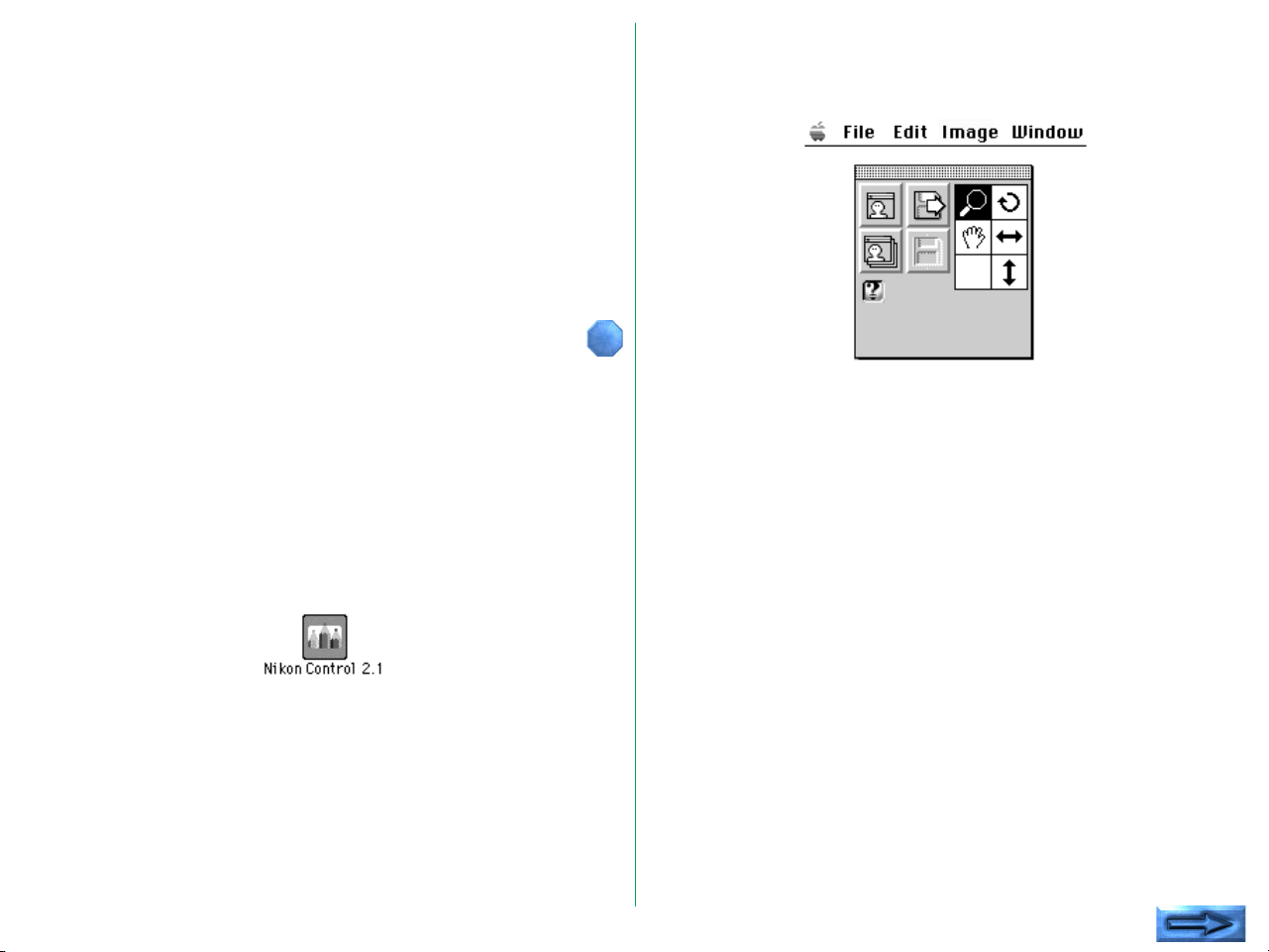
Double-click the Nikon Control icon.
After Nikon Control is launched, the following Control palette
appears on the desktop, and File, Edit, Image, and Window
menus appear on the menu bar.
- 6 -
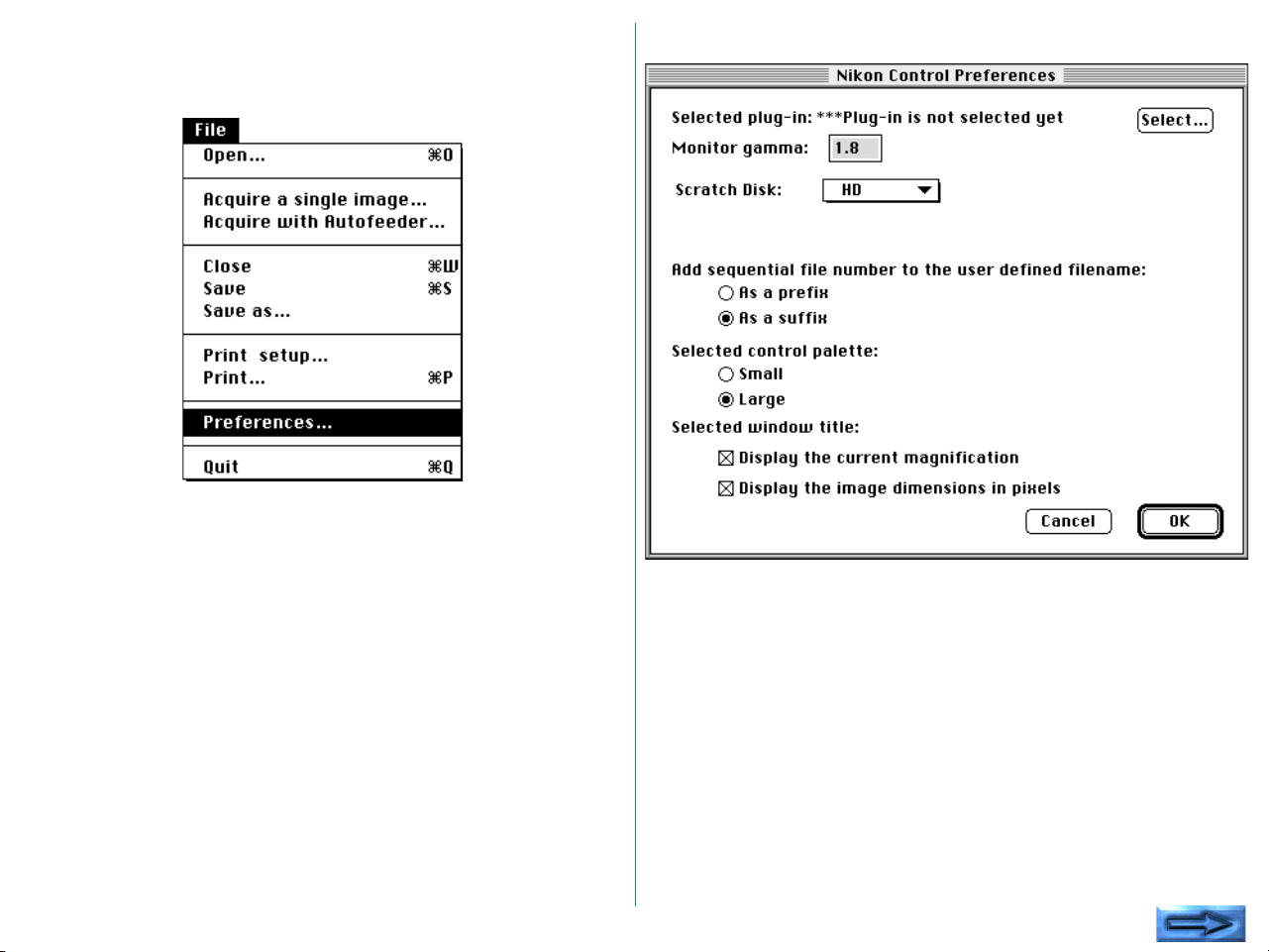
You must first select the Nikon Scan plug-in before you can
begin scanning. To do so, choose Preferences… from the File
menu.
The Preferences dialog box appears.
- 7 -
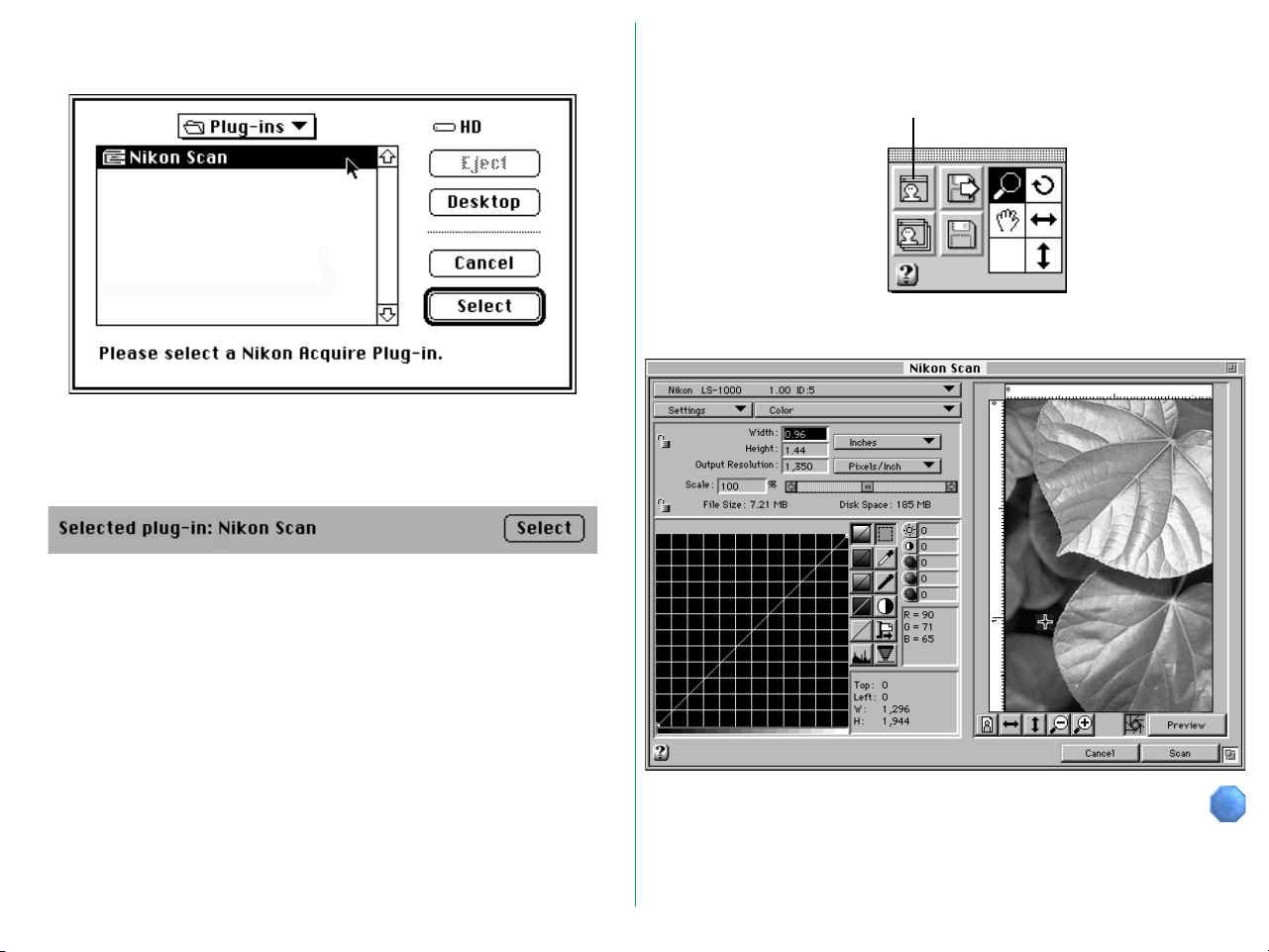
When the Select button is clicked, the Plug-in Selection dialog
box appears.
Select the required plug-in from this dialog box, and click the
Select button. The selected plug-in is displayed after “Selected
plug-in:” in the Preferences dialog box.
After quitting the Preferences dialog, click the Acquire button
on the Control palette.
Aquire button
The Nikon Scan Main dialog box appears.
- 8 -
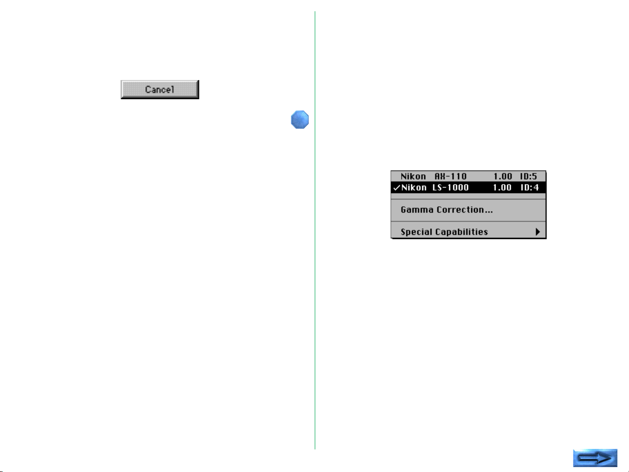
Quitting
Clicking the Cancel button in the Nikon Scan Main dialog box
will return you to Nikon Control or to your current imaging
application.
3.2 Main Dialog Box
Nikon Scan will automatically detect which scanners are
connected and will display the Main dialog items and menus
appropriate for the scanner you select. (The Main dialog box
items will vary slightly, depending on the selected scanner.)
If multiple Nikon scanners are connected and powered on, first
choose the scanner you are going to use from the pop-up
menu at the top left corner of the Main dialog box. Only
scanners supported by Nikon Scan will be visible in this pop-up
menu.
Note: Depending on what devices are actually connected to your
computer, the options which will appear in the pop-up menu above
may differ from those shown here.
- 9 -
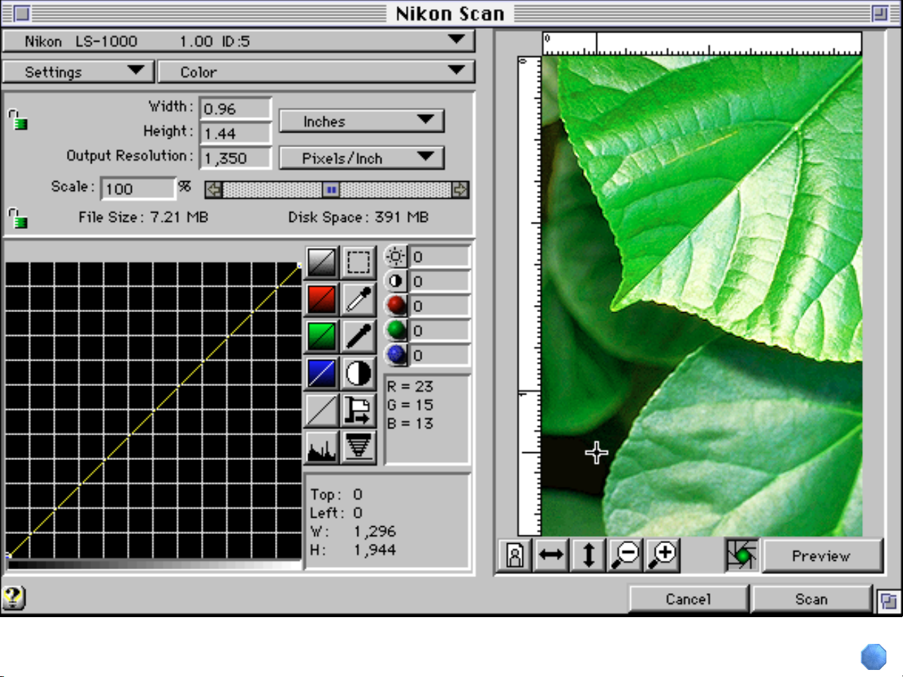
Main Dialog Box
Place the cursor over a control (button,
menu, or window) for a brief description
of its function. Clicking a control will
open this manual to the section in which
its function is explained in greater detail.
To clear this explanation from the screen,
click the Close button below.
*
Close
- 10 -
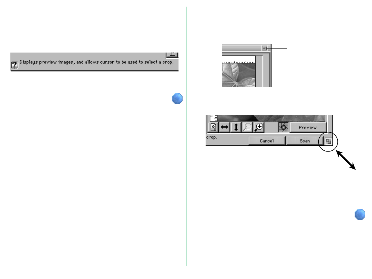
Interactive Help
Clicking the Help button at the bottom left of the dialog box
activates the Interactive Help function. Passing the cursor over
a dialog item automatically displays appropriate Help text in the
message display area.
The Interactive Help display disappears when the Help button is
clicked again.
Changing the Size of the Main Dialog Box
The size of the Main dialog box can be enlarged to fill your
entire display by clicking the fit-to-screen box at the upper right
corner.
Fit to screen
The size of the Main dialog box can also be adjusted by
dragging the re-size box at the bottom right corner.
Note: Making the dialog larger than 800 x 600 pixels may
require you allocate additional memory to your imaging application
to accommodate the larger preview image.
- 11 -
3.3 Basic Scanning
This section gives a brief description of the standard acquisition
procedure after the Main dialog box is displayed. The individual
buttons and menus are explained in detail in the following
chapters.
Choosing the Scanner
Nikon Scan will automatically detect which scanners are
connected and will display the Main dialog items and menus
appropriate for the scanner you select. The Main dialog box
items will vary slightly, depending on the selected scanner.
If multiple Nikon scanners are connected and powered on, first
choose the scanner you are going to use from the pop-up
menu at the top left corner of the Main dialog box. Only
scanners supported by Nikon Scan will be visible in this pop-up
menu.
Positioning Media
Insert or position the media to be scanned as described in your
scanner’s hardware manual.
Ejecting Film (film scanners only)
To eject film, click the button shown below. If you are using the
optional SF-100 Auto Slide Feeder with the LS-1000, clicking
this button will eject the current slide and set the next one. If
you are using the LS-4500AF, you can also eject the film by
pressing the scanner’s Eject button.
Media Type
Choose the media type to be scanned.
Note: Depending on what devices are actually connected to your
computer, the options which will appear in the pop-up menu above
may differ from those shown here.
Note: The above menu may differ depending on the scanner and
options used. Please see the appendix appropriate to the scanner
you are using.
- 12 -
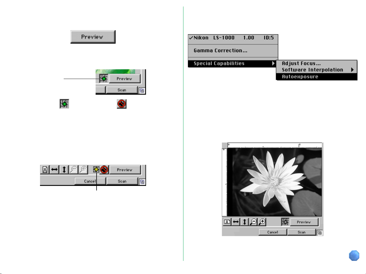
Preview
Clicking the Preview button starts a preview operation.
Before the preview process begins, a prescan operation will be
carried out if the Prescan check box is turned on.
Prescan
check box
PRESCAN ON
Note: Even if the prescan check box is turned on, the LS-4500AF
will not conduct a prescan operation if the cropping area has not
been changed.
If the Prescan check box is turned off when a prescan is
required, the following indication will appear.
PRESCAN OFF
In this case you can carry out the prescan operation after the
preview is completed by choosing Autoexposure from the
Special Capabilities menu.
Note: Depending on the scanner you have selected, the options
which appear in the pop-up menu above may differ from those
shown here. Please see the appendix appropriate to the scanner
you are using.
Once the preview operation is completed, an image will be
displayed in the Preview display area.
This indication appears when a prescan operation has not been carried out
- 13 -
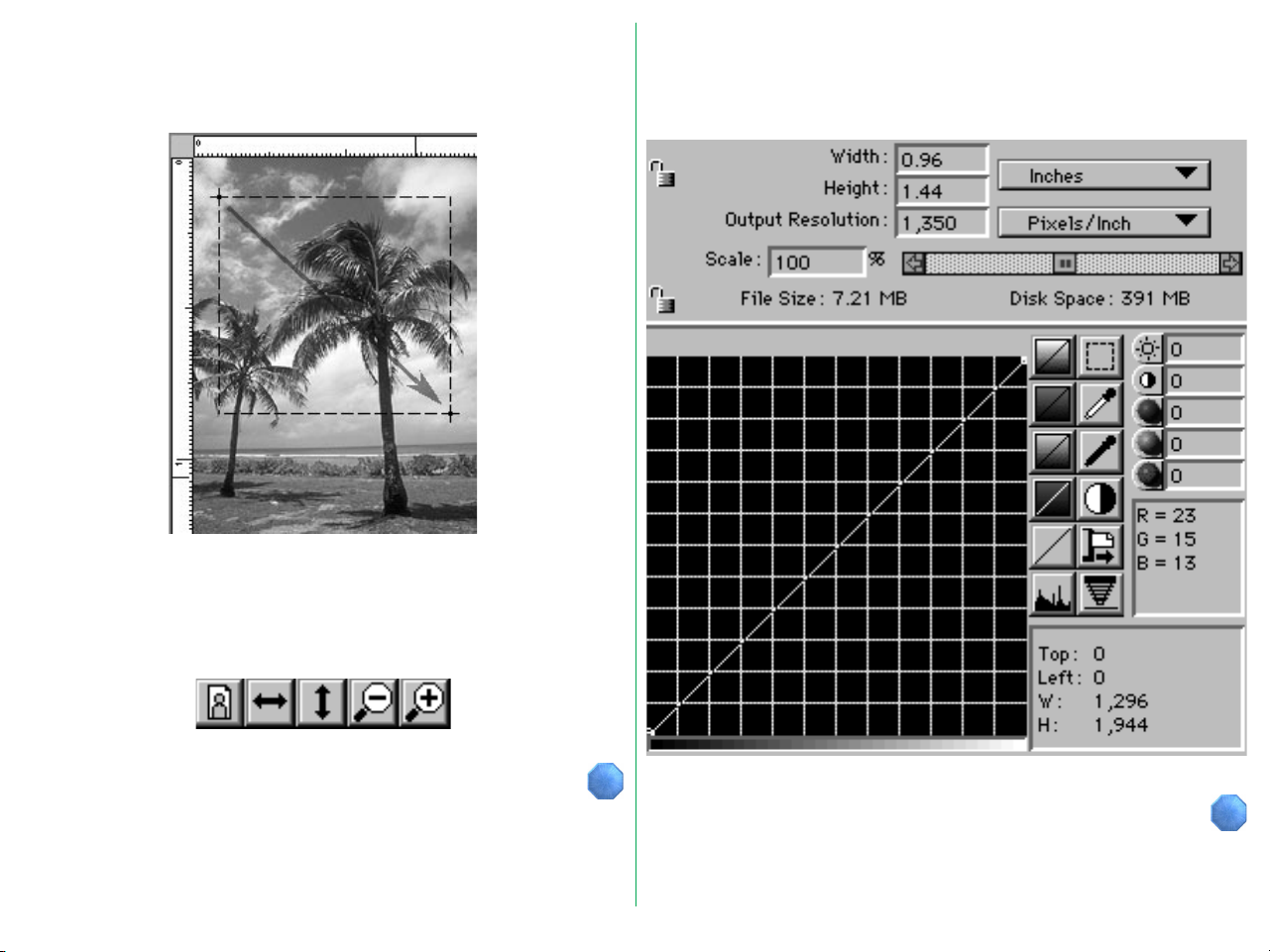
Cropping
Setting Size, Resolution, and Image Adjustment
Using the mouse, click and drag a bounding box to specify a
rectangular crop area in the preview image display area.
Using the five buttons shown below, the image displayed in the
preview area by the preview operation can be rotated 90˚ to
landscape or portrait orientation, flipped vertically or
horizontally, and enlarged or reduced.
You can change settings such as the resolution, scale, contrast,
gamma curve, and other parameters, as required.
- 14 -
Scanning
When the Scan button is clicked, scanning is carried out in
accordance with the settings made, and the acquired image is
passed to the imaging application, or to Nikon Control.
- 15 -
4. Scanning Conditions
Except where otherwise noted, the operating procedures
covered in the present chapter are identical for all scanners
supported by Nikon Scan. Features specific to each model are
covered in Appendix A, Features Specific to the LS-20 and
LS-1000, Appendix B, Features Specific to the LS-4500AF, and
Appendix C, Features Specific to the AX-110 and AX-210.
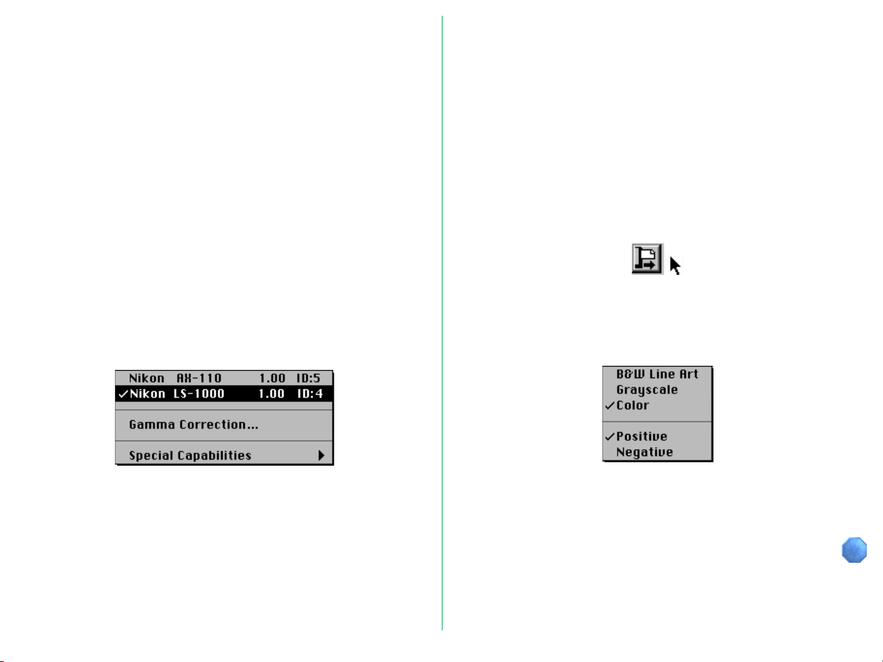
4.1 Choosing the Scanner
The names and SCSI IDs of the connected scanners are shown
in the menu at the top left corner of the Main dialog box.
Nikon Scan will automatically detect which scanners are
connected and will display the Main dialog items and menus
appropriate for the scanner you select. The Main dialog box
items will vary slightly, depending on the selected scanner.
If multiple Nikon scanners are connected and powered on, first
choose the scanner you are going to use from the pop-up
menu at the top left corner of the Main dialog box. Only
scanners supported by Nikon Scan will be visible in this pop-up
menu.
Note: Depending on what devices are actually connected to your
computer, the options which will appear in the pop-up menu above
may differ from those shown here.
- 16 -
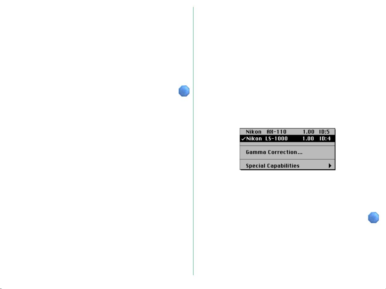
4.2 Setting the Application Gamma
You can set an application gamma value and decide whether
you want to use the application gamma correction function.
Choose Gamma Correction… from the pop-up menu at the
top left corner of the Main dialog box.
Note: Depending on the scanner selected, the options which
appear in the pop-up menu above may differ from those shown
here. Please see the appendix appropriate to the scanner you are
using.
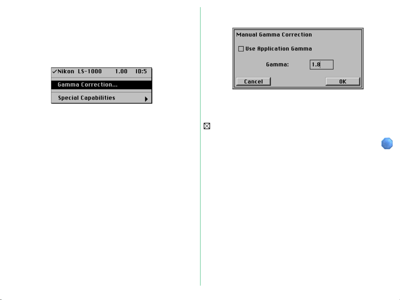
When Gamma Correction… is chosen from the menu, the
Manual Gamma Correction dialog box appears.
You can set a Gamma value between 1.0 to 3.0 when the Use
Application Gamma check box is unchecked. If you want to
use the application gamma correction value, insert a check mark
and click the OK button.
- 17 -
4.3 Positioning Media
4.5 Choosing the Media Type
Insert or position media as described in your scanner’s
hardware manual.
4.4 Ejecting Film (film scanners only)
To eject film, click the button shown below (this button is not
displayed when an AX-110 or AX-210 flatbed scanner is
selected). If you are using the optional SF-100 Auto Slide
Feeder with the LS-1000, clicking this button will eject the
current slide and set the next one.
Note: With the LS-4500AF, you can also eject the film by pressing
the scanner’s Eject button.
After the film eject button has been clicked, a prescan operation
will be carried out automatically.
Media Type Selection
Choose the type of media to be scanned.
Note: The above menu may differ depending on the scanner and
options used. Please see the appendix appropriate to the scanner
you are using.
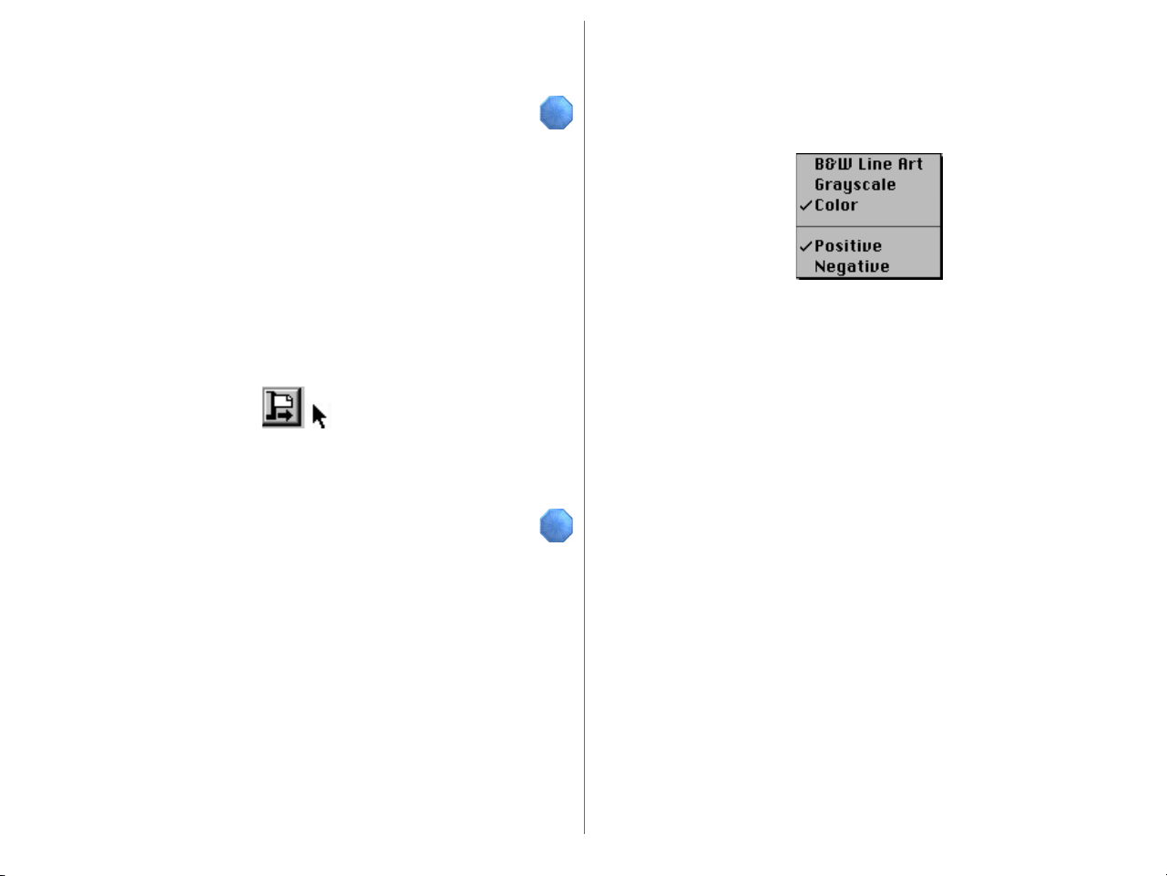
Choose one of the following from the upper part of the Media
Type menu.
B&W Line Art: To scan black and white binary images
Grayscale: To scan grayscale images
Color: To scan color images
Choose one of the following from the lower part of the Media
Type menu.
Positive: To scan positive images
Negative: To scan negative images
- 18 -

Filter Selection
With some images good results can be obtained by using a
different color filter from the default filter in grayscale scanning,
and a filter selection function is provided for this purpose. This
function can only be used to produce grayscale scans, and is
useful for ‘dropping out’ unwanted colors, such as document
stains, etc.
If you pull down the Media Type menu while holding down the
option key on the keyboard, the filter selection menu appears
at the end of the Media Type menu.
Choose the filter you want to use from the menu.
- 19 -

4.6 Crop/Preview Area Buttons
Orientation
The preview image acquired after clicking the Preview button is
displayed in the crop/preview area.
Using the five buttons below the preview area, the image
displayed by the preview operation can be rotated to landscape
or portrait orientation, flipped vertically or horizontally, and
enlarged or reduced.
Using the appropriate combination of these buttons will
streamline the cropping process.
Clicking this button changes the entire preview area
display (including any existing crop marquis) from
portrait to landscape orientation. The illustration on
the button changes according to the display
orientation.
- 20 -

Clicking this button changes the entire preview area
display (including any existing crop marquis) from
landscape to portrait orientation. The illustration on
the button changes according to the display
orientation.
Flip
The entire preview area display (including any existing
crop marquis) is flipped horizontally by clicking this
button.
The entire preview area display (including any existing
crop marquis) is flipped vertically by clicking this
button.
- 21 -

When the original image is flipped horizontally or vertically, the
corresponding Flip button appears to have been pressed, and
will remain in a depressed position, as shown below. Clicking
the button again restores its original appearance.
Zoom
When the Zoom-in button is clicked, the crop area fills
the entire Preview area. After a zoom-in operation,
the original display is restored by clicking the Zoomout button.
If Zoom-in or Zoom-out functions are unavailable (e.g. when
the minimum or maximum image size is shown), the
appropriate button is dimmed (inactive) and cannot be clicked.
- 22 -

4.7 Cropping
You can use your cursor in the crop/preview area, to set up a
new crop, or to move or change the size of the current crop
area.
Establishing a New Crop
After the preview image is displayed, locate the cursor at any
starting point on the preview (the top left is shown in the
example), and then drag the cursor to another location
(bottom right in the example), thus forming a rectangle, which is
referred to as a ‘marquis’ of ‘marching ants’.
Note: ‘Dragging’ means moving the mouse while holding the
mouse button down.
Note: For reasons involving the compression and display of the
preview image, there may be a slight difference between the crop
area specified on the screen and the area that is actually scanned.
When cropping an image, allow sufficient safety margin to ensure
that important elements are not cropped out.
The entire preview area can be re-selected by double-clicking
anywhere in the preview window, or by choosing Select All
( A).
- 23 -

Moving the Crop Area
To change the position of the crop rectangle, simply locate the
cursor so that it is inside the frame and then drag the frame to
the desired position.
Changing the Size of the Crop Area
To change the size of the crop area, drag a side or corner of
the crop frame. When a side is dragged, the area will change
only in the vertical or horizontal direction. When a corner is
dragged, the size of the area will change both vertically and
horizontally. Note the type of cursor used for each change.
- 24 -

4.8 Crop Size Control
These controls let you set the output size, output resolution,
and scale.
Dimensions
The scanned output size can be specified by entering width and
height values. If an unacceptable value is entered, it will be
displayed in red. When the size is changed by cropping the
Preview, the numbers displayed in the size value edit boxes will
also change at the same time.
The units for width and height can be selected from the pop-up
menu. When this selection is changed, the values in the boxes
are converted to the equivalent new units.
Selection Unit
Pixels Pixel
Inches Inch
cm Centimeters
mm Milimeters
Picas Pica
Points Point
Note: If the unit is changed, the ruler and location display also
change accordingly.
The width/height aspect can be locked by clicking the padlock
icon located to the left of the width and height input boxes (the
icon will change from green to red). If a new value is entered
for either width or height when the aspect ratio is locked, the
other value will automatically be changed to maintain the
specified aspect ratio.
- 25 -

Cropping Coordinates
The location of the current crop is given by the absolute
numerical position of its top and left sides. The distance, in
pixels, from the top to the bottom of the crop is shown as the
pixel height, while the distance from the left to the right side is
the pixel width. These coordinates are displayed in pixels,
regardless of the units selected for Width and Height (and
corresponding ruler display) in the size control area.
Output Resolution
Enter the desired resolution in the Output Resolution field in
the dialog box in order to set the output resolution. The
resolution specified here refers to the output resolution of the
scanned image; enter a value suitable for the final purpose of
the scan.
If an unacceptable value is entered, it will be shown in red.
The units for resolution can be selected from the pop-up menu.
When this selection is changed, the value in the box is
converted to the new units.
Selection Unit
Pixels/Inch Pixels/Inch
Pixels/cm Pixels/Centimeter
Pixels/mm Pixels/Milimeter
Pixels/Pica Pixels/Pica
Pixels/Point Pixels/Punto
- 26 -

Scale
‘Scale’ means the relative scale of the output resolution or size,
and input resolution or size. If input and output size and
resolution are the same, the scale is 100%. The Scale value can
be specified either by entering a value or by dragging the slider
with the mouse. If an unacceptable value is entered it will be
shown in red. The Scale is always shown as a percentage
increase from the original size, to the final scanned size.
Modifying the size of the crop rectangle while the width and
height aspect ratio is locked, will change the Scale value, not the
final output width and height values.
File Size and Disk Space
The file size and amount of free disk space are shown below
the Scale controls.
Note: If the file size calculated from the size, resolution, and scale
settings is too large to be saved within the available disk space, the
value will be highlighted in yellow.
The padlock icon to the left of the File Size information item
will lock in the file size, permitting the size and resolution to
change in proportion to each other without changing the final
quantity of scan data - the total number of pixels scanned.
Locking file size simultaneously locks the width/height aspect
ratio.
Note: You should check the File Size and Disk Space available
before starting a final scan. If the required space for a scan
exceeds the available space, the file size needed will be displayed
in highlighted text. It is unnecessary to cancel the plug-in to delete
unwanted files from your disk. Click outside the plug-in dialog box,
and navigate using the Finder, deleting unneeded files as necessary.
- 27 -

4.9 Autofocus (film scanners only)
The focus of the image can be adjusted by clicking the
Autofocus button shown below (this button is not displayed
when an AX-110 or AX-210 flatbed scanner is selected).
You can choose a location in the image as the focus position by
clicking this button while simultaneously holding down the
option key. If you click the Autofocus button without specifying
a focus position, the autofocus position chosen will be the
center of the image.
You can cancel the focus position cursor by clicking the Return
to crop button.
Focus Position Cursor
- 28 -

4.10 Adjust Focus (film scanners only)
This function allows you to adjust focus to compensate for
warping of the film or for differences in the thickness of slide
mounts.
To use the Adjust Focus function, choose Adjust Focus… from
the Special Capabilities submenu located on the pull-down
menu at the top left corner of the Main dialog box (the Special
Capabilities menu for the AX-110 and AX-210 does not
include the Autofocus function).
Note: The menu for the LS-4500AF differs from that shown
above. See Appendix B.
When Adjust Focus… is chosen from the Special Capabilities
submenu, the following dialog box appears.
Drag the slider or input the desired value, then click the OK
button.
Note: The values shown at the ends of the slider bar will vary
depending on the autofocus position and the scanner model. The
autofocus position always has a value of zero.
- 29 -

4.11 Autoexposure
The Autoexposure function can be used to perform a prescan
after a preview operation has been completed.
If you click the Preview button when the Prescan check box is
turned off or while holding down the option key, the prescan
operation will be skipped. In this case, you can carry out a
prescan operation after preview by selecting Autoexposure
from the Special Capabilities submenu.
Note: The pop-up menu shown above is for the LS-1000. The
corresponding pop-up menus for the LS-4500AF and for the
AX-110 and AX-210 are different. Please see the appendix
appropriate to the scanner you using.
The prescanning operation begins immediately on your selecting
the Autoexposure function from the Special Capabilities
submenu.
- 30 -

5. Image Compensation
This chapter explains how to adjust continuous tone brightness,
line art threshold, contrast, and color balance. All these
settings are made using buttons or text edit boxes. The results
of compensation can be checked with a preview scan.
The appearance of the Main dialog box depends on the Media
Type setting, as shown below.
5.1 Brightness / Threshold
This control is used to set the brightness for a Color or
Grayscale image, or the threshold value for a B&W Line Art
image.
When this button is clicked and held down, a slider bar pops
up. The value is set by dragging the slider to the left or right
while holding down the mouse button. The same result can be
achieved by entering a value directly in the box to the right of
the button.
Color Grayscale B&W Line Art
When the slider is dragged in the plus direction, the images will
be brighter and the black point will begin to float above
maximum black. When dragged in the minus direction, the
images will become darker and dimmer.
For a B&W Line Art image, the set value is the threshold value.
Brightness adjustment range: -100 to 100
Threshold adjustment range: 0 to 255
- 31 -

5.2 Contrast
5.3 Color Balance
This control is used to set the contrast for Color or Grayscale
images. A contrast setting is not used for B&W Line Art
images.
When this button is clicked and held down, a slider bar pops
up. The value is set by dragging the slider to the left or right
while holding down the mouse button. The same result can be
achieved by entering a value directly in the box to the right of
the button.
When the slider is dragged in the plus direction, the black point
and white point input values will be restricted, thus steepening
the tone curve and producing punchier images with less
gradation subtlety. When dragged in the minus direction, the
black output values will be raised and the white point output
values lowered, thus flattening the tone curve and producing
‘flatter’ or ‘muddier’ images with more gradation subtlety.
Adjustment range: -100 to 100
The color balance is adjusted using three controls for Red,
Green, and Blue. These three controls only appear when
‘Color’ has been set as the Media Type.
Red
Green
Blue
When one of these buttons is clicked and held down, a slider
bar pops up. The value is set by dragging the slider to the left
or right while holding down the mouse button. The same result
can be achieved by entering a value directly in the box to the
right of the button.
You can adjust overall color balance by emphasizing or deemphasizing each of the three primary colors of the scan.
Unlike brightness compensation, in which the amount of the
Red (R), Green (G), and Blue (B) components in the image are
changed simultaneously, affecting the brightness of the image as
a whole, color balance adjustment permits individual
compensation for each of these colors.
Adjustment range: -100 to 100
- 32 -

5.4 Level display
RGB values or CMY percentages at the cursor position are
displayed while the cursor is over the crop/preview area. The
values can be switched between absolute RGB pixel values (in
8-bit level equivalent) and CMY percentages, by clicking within
the boundary surrounding the density display area.
For grayscale images, the L (luminance in 8-bit level
equivalence) or K (the black density percentage) value at the
cursor position is displayed.
- 33 -

6. Gamma Curves
6.1 Viewing the Gamma Curves
Selective gamma curve editing is essential for the highest-quality
scanning. In many cases, the factory default gamma curves will
yield excellent results. These default gamma curves are well
suited to the widest variety of original media. However, under
certain circumstances, you may want to use other gamma
curves.
When the Media Type is ‘Color’, four gamma curves are
displayed.
- 34 -

When the Media Type is ‘Grayscale’, only one gamma curve is
displayed.
When the Media Type is set to ‘Color’, you can edit one master
curve and three primary curves, i.e., for Red, Green, and Blue.
When the Media Type is set to ‘Grayscale’, you can edit a
grayscale curve only.
Each of the Red, Green and Blue gamma curves is unique. The
master curve provides a simple means of adjusting all of the
primary curves equally. Thus, you do not have to adjust each
primary curve individually.
This two-dimensional graph represents the input/output transfer
function. The horizontal axis represents the input, or original
values. The vertical axis represents the output, or new values.
A diagonal line connecting the lower-left and upper-right
corners would represent a linear transfer function. For
example, an input value of 100 would produce an output value
of 100. Similarly, an input value of 200 would produce an
output value of 200, and so on. A horizontal line running along
the bottom border would map all inputs into a zero output,
consequently creating a black image. A line beginning at the top
left corner, and ending in the bottom right corner, would
produce a negative image.
- 35 -

6.2 Viewing the Histogram
At times it may be useful to view the histogram of the preview
image. A histogram is a statistical representation of the
densities in an image. A histogram will be displayed when the
Histogram button is clicked and held. This control is active
when either Grayscale or Color is selected as the Media Type
in the Main dialog box.
The histogram will be displayed as long as the button is held
down.
The histogram’s horizontal axis represents the pixel intensity or
brightness, the darker values appearing on the left and the
lighter values on the right. The vertical axis is a statistical
representation of the number of occurrences of each pixel
value over the entire image. The histogram therefore
represents a graphical and statistical view of the overall
brightness an image.
- 36 -

6.3 Modifying the Gamma Curves
Modifying the gamma curves is relatively easy, but modifying
them correctly is not. While the effects of altering the master
curve are straightforward, the relationships between the Red,
Green and Blue gamma curves are far more complex, and much
more difficult to control.
The gamma curves can be modified manually or automatically.
The manual mode involves moving points on the gamma curves
with the mouse, thereby graphically reshaping the curve.
Specifying the Gamma Curve
To the right of the graph are four buttons—from top to
bottom, the Master Curve button, and the Red, Green, and
Blue Curve buttons. The Grayscale Curve button appears only
when the Media Type is set to Grayscale.
Master Curve
Red
Green
Blue
When one of these buttons is clicked, the gamma curve
corresponding to that button is selected for editing. This mode
is maintained until another button is clicked.
- 37 -

Graphically Altering the Gamma Curves
The individual gamma curves in the gamma curve window can
be manually altered by clicking the mouse at points on the
gamma curve and dragging, thus reshaping the curve.
You will notice that changes to the shape of the gamma curves
will cause corresponding changes to the tonal quality of the
displayed image, as seen in the preview window. As the curve
is altered, a curve-fitting software algorithm redraws the new
curve.
Forcing the Gamma Curves to Linear
To reset curves to a linear state, clicking the Linear button
shown below ‘forces’ whichever gamma curve is active to linear.
Option-clicking the Linear button will force all three gamma
curves to linear.
Choosing the Reset Color Controls command from the
Settings menu will force the master, Red, Green, and Blue
gamma curves to linear, and brightness and contrast, R, G, and B
adjustment values to zero.
- 38 -

Setting the Black Point
The Black Point represents the darkest point in the image.
Since the density range of the original media might exceed the
dynamic range of the scanner, the scanner’s tonal range needs
to be used as efficiently as possible. The Black Point is typically
selected so that all values in the image that are darker than this
point can be mapped, or converted to black without affecting
the quality of the image.
For example, suppose that the darkest area within the image,
that you know to represent a true black, has a value of 10 in the
scanned data. Values 0–9 would be wasted since no pixel in
the image would have a value lower than 10. By setting the
Black Point to 10, the data would be re-mapped so that a value
of 10 from the scanner would produce a 0. All the data values
would then be meaningful.
To set the Black Point, click the Black Point button.
After the Black Point button is clicked, position the mouse
cursor over the image in the preview window and select a pixel
value to be used as the darkest point in the image. Watch the
Pixel Value display closely as you move the cursor across the
image to enable you to choose the right value to modify. If you
are unsure, then zoom in on the area of interest to enhance the
detail and increase the accuracy of your selection.
Black point cursor
The pixel you select will be mapped to the new Black Point, or
reference point for maximum black (often called ‘dmax’, for
‘maximum density’). When the Black Point is selected, the
active gamma curve is automatically adjusted to reflect this
selection. This tool can be used with any gamma curve,
although it is most effective when used with the master gamma
curve, as it provides a ‘neutral’ black point, which is normal for
many images.
- 39 -

When you decide on the pixel you want to use as the Black
Point of the image, clicking the mouse forces the gamma curves
to use this value as the minimum value in the preview window.
Any pixels darker than the black point will be set to the
minimum value. The result of this new curve is approximated in
the preview window. Observe the increase in contrast, and
also the reduced White Point, covered in the next section.
Setting the White Point
The White Point represents the lightest point in the image, thus
providing a function opposite to that of the Black Point. Like
the Black Point, however, selection of a White Point reduces
the tonal range of the scanner so as not to waste any of its
tonal range on light areas that are not actually present in the
original.
The White Point is typically selected so that all values in the
image that are lighter than this point can be mapped, or
converted to white without affecting the quality of the image.
To set the White Point, click the White Point button.
New black point
The Black Point cursor can be restored to its ‘cropping’ state,
from the ‘eyedropper’ state, by clicking the Return to Crop
button.
- 40 -

After the White Point button is clicked, position the mouse
cursor over the image in the preview window and select a pixel
value to be used as the lightest point in the image. Watch the
Pixel Value display closely as you move the cursor across the
image to enable you to choose the right value to modify. If you
are unsure, then zoom in on the area of interest to enhance the
detail and increase the accuracy of your selection.
White point cursor
The pixel you select will be mapped to the new White Point, or
reference point for maximum lightness (often called ‘dmin’, for
‘minimum density’). When the White Point is selected, the
active gamma curve is automatically adjusted to reflect this
selection. This tool can be used with any gamma curve,
although it is most effective when used with the master gamma
curve, as it provides a ‘neutral’ white point, which is normal for
many images.
When you decide on the pixel you want to use as the White
Point of the image, clicking the mouse forces the gamma curves
to use this value as the maximum value in the preview window.
Any pixels lighter than the White Point will be set to the
maximum value. The result of this new curve is approximated
in the preview window.
New white point
The White Point cursor can be restored to its ‘cropping’ state,
from the ‘eyedropper’ state, by clicking the Return to Crop
button.
- 41 -

Automatic Contrast Adjustment
If you prefer, the Nikon Scan plug-in is capable of selecting
optimal neutral Black and White Points for you. The Automatic
Contrast Adjustment control in the plug-in will usually produce
excellent results. Simply click the Contrast Adjust button.
The software will analyze the portion of the preview image
contained within the cropped region of the preview and
automatically select an optimum Black Point and White Point.
The active gamma curves will be modified automatically.
Note that this may sometimes lead to undesirable color
balance. If for example, the original image is of a predominantly
‘warm-toned’ scene, such as a sunset, then the neutral highlight
produced by Autocontrast, or the White point eyedropper,
would be too ‘cold’ for the subject matter of the image.
- 42 -

7. Saving and Loading Settings
Using the Settings pop-up menu, you can save the settings you
have made, or load previously saved settings. This may be
convenient for repetitive scanning with particular crops and
resolutions, or when using a complex gamma correction to
improve reproduction.
Settings include the following items:
• Scanner selection, media type, width and height units, width
value, height value
• Aspect and file size locked/unlocked status, output resolution
value, scale value, resolution unit
• Master, R, G, and B curves, brightness and contrast, R, G, and
B adjustment values
• Orientation, horizontal and vertical flip status, help ON/OFF
status, crop area size and location
• Zoomed preview area
- 43 -

7.1 Saving Settings
You can save the current Main dialog box in the Nikon Scan
Preferences folder using the Save Settings… function.
When Save Settings… is chosen from the Settings menu, a
dialog box appears to let you name the new settings.
If settings have previously been saved using the entered name,
the following dialog box will appear when you click the OK
button.
If you want to overwrite the previous settings, click the OK
button. If you want to keep the previous settings, click the
Cancel button and enter a different name for the new settings.
If you pull down the Settings menu after performing the save,
you will see that the name under which the settings were saved
has been added at the end of the menu. If there are a number
of settings, the names of each of the settings are displayed.
When you enter a name and click the OK button, the settings
are saved in the System folder under that name.
- 44 -

7.2 Deleting Settings
7.3 Recalling Settings
You can delete saved settings using Delete Settings function.
When Delete Settings is chosen from the Settings menu, a
submenu appears to let you specify the name to be deleted.
When you select a name, the following dialog box appears.
To delete the settings, click the OK button.
Settings saved in the System folder include factory default
settings and last session settings as well as user settings.
Factory Defaults settings are made when the product is
shipped, and cannot be changed or deleted.
Last Session settings are saved automatically when you exit the
plug-in by clicking the Scan button. Last Session settings cannot
be deleted.
You can recall Factory Default settings, Last Session settings, or
settings saved using the Save Settings… function. These are
displayed at the end of the Settings menu.
When the settings are deleted, the name displayed at the end
of the Settings menu is also deleted.
When you choose the settings to be recalled, those settings are
immediately loaded into the Main dialog box.
Note: Last Session will not be displayed on the first use after
installation.
- 45 -

7.4 Exporting Settings
You can save the current Main dialog box settings to a file using
the Export Settings… function. Unlike the Save Settings…
function, which saves settings within the plug-in ‘system’ folder
(the Nikon MAID folder contained in the Preferences folder
within the System folder), the Export Settings function saves
them to a file that can be located anywhere you can navigate to
using the standard file dialog box. A file to which settings have
been saved using Export Settings function can be read using the
Import Settings function.
To save the current settings to a file, choose Export Settings…
from the Settings menu. We recommend that you save
‘mission critical’ settings data using Export Settings….
The Export dialog box appears.
When you click the Save button after specifying the folder to be
saved to, and entering the file name, the current settings are
saved to that file.
- 46 -

7.5 Importing Settings
7.6 Reset Color Settings
Using the Import Settings… function, you can read the
contents of a file saved with the Export Settings… function into
the Main dialog box.
To read the contents of a settings file, choose Import
Settings… from the Settings menu.
The Import dialog box appears.
You can reset the modified gamma curves and image
compensation.
Choosing the Reset Color Controls command from the
Settings menu will force the Master, Red, Green, and Blue
gamma curves to linear, and brightness and contrast, R, G, and B
adjustment values to zero.
When you click the Open button after opening the folder
containing the settings and selecting a file, the contents of that
file are read.
- 47 -

Appendix A: Features Specific to the LS-20 and LS-1000
A.1 Software Interpolation
Software Interpolation is used to provide precise image scaling
and resolution.
Except that the LS-20 does not support the optional SF-100
Auto Slide Feeder, the operating procedures for the LS-20 and
LS-1000 are identical. The following section describes features
specific to the LS-20 and LS-1000.
The pop-up menu at the top left corner of the Main dialog box
includes the Special Capabilities sub-menu. Choose Software
Interpolation from the Special Capabilities menu.
You can choose any one of the following from the Software
Interpolation menu.
Bilinear: Interpolation with emphasis on accuracy
Nearest Neighbor:
Interpolation with emphasis on high-speed
processing
None: No interpolation is performed
- 48 -

Appendix B: Features Specific to
Choose any one of the following items from the film format
submenu.
the LS-4500AF
The following sections describe features specific to the LS4500AF.
B.1 Film Format
The film format to be scanned can be chosen from the Media
Type menu. Resolution, maximum scanning area, and prescan
area are automatically altered to reflect the format selected.
LoRes: Uses the low resolution (1000 x 2000 dpi)
optical system
HiRes: Uses the high resolution (3000 x 3000 dpi)
optical system for 35mm film using a single
frame holder
4"x5": 4˝ x 5˝ film (low resolution)
6x6--9: Film measuring from 6 x 6 to 6 x 9 (low
resolution)
6x4.5: Film measuring 6 x 4.5 (low resolution)
35mm: 35mm film (high resolution)
- 49 -

B.2 Preview Quality
B.3 Final Scan Quality
Setting preview quality allows you to chose whether preview
operations are to be performed in high speed mode or in high
quality mode.
Select one of the following from the Preview Quality submenu.
Highest Speed:
Preview with emphasis on speed
Normal: Normal preview
Highest Quality:
Preview with emphasis on quality
Setting final scan quality allows you to choose whether scanning
takes place in high speed mode or in high quality mode.
Select one of the following from the Final Scan Quality
submenu.
Highest Speed:
Scan with emphasis on speed
Normal: Normal scan
Highest Quality:
Scan with emphasis on quality
Under normal circumstances the best choice is Highest Quality.
- 50 -

B.4 Make Shading
B.5 Sharpening
After replacing the lamp, you must perform lamp calibration
using the Make Shading function before you can operate the
scanner (to replace the lamp, follow the directions given in the
LS-4500AF hardware manual).
You must use this function whenever you replace the lamp.
Note: The film holder must ejected before this function is used, as
otherwise lamp calibration will not proceed correctly.
The pop-up menu at the top left corner of the Main dialog box
includes the Special Capabilities sub-menu. Lamp calibration
begins immediately on your selecting Make Shading from the
Special Capabilities submenu.
It is often necessary to sharpen images prior to reproduction
since there are usually losses in definition when going to press.
To enhance edge contrast, choose Sharpening from the Special
Capabilities menu.
Choose any one of the following from the Sharpening menu.
• Sharpen More
• Sharpen
• None
• Blur
• Blur More
- 51 -

Appendix C: Features Specific to the AX-110 and AX-210
The following sections describe features specific to the AX-110
and AX-210 flatbed scanners. The operating procedures for
the two models are identical.
C.1 Main Dialog Box
The Main dialog box for the AX-110 and AX-210 is shown
below.
Note that the Main dialog box for flatbed scanners lacks both
Eject Film and Autofocus buttons, and that the rulers in the
Preview area differ from those shown for film scanners in scale
and point of origin.
- 52 -

C.2 Using Option Adapters
When the optional transparency adapter or ADF (Auto
Document Feeder) is fitted to the AX-110 or AX-210, a
submenu is added to the Media Type menu to enable the
option.
Using the Transparency Adapter
When the optional transparency adapter is fitted to the AX110 or AX-210, additional items appear at the bottom of the
Media Type pop-up menu.
Choose one of the following from the lower part of the Media
Type menu.
Transparency: To scan transparency images
Reflective: To scan reflective images
Note: When scanning transparencies with the Media Type set to
Negative, the prescan operation will be optimized for the currently
selected crop. If a new crop is selected after preview, it may be
necessary to carry out the prescan operation again. After changing
the crop area, it is recommended that you click the Zoom-in
button to conduct a preview with the prescan optimized for the
new crop.
- 53 -

Using the ADF (Auto Document Feeder)
When the optional ADF (Auto Document Feeder) is fitted to
the AX-110 or AX-210, the ADF submenu appears at the
bottom of the Media Type menu.
Choose any one of the following from the ADF submenu.
ADF Off: Disables the ADF. The document positioned
on the document setting glass will be scanned.
ADF On US Letter:
Enables scanning of letter-sized documents
placed on the ADF.
Note: When the AF-10 Auto Document Feeder is attached to
your scanner, automated continuous scanning is available with
applications supporting continuous acquire, such as Photoshop
version 3 or above or EasyPhoto 1.5. Continuous scanning can be
initiated by clicking the Scan button in the Main Dialog Box while
holding down the Option key.
ADF On US Legal:
Enables scanning of legal-sized documents
placed on the ADF.
- 54 -

C.3 Software Interpolation
C.4 Sharpening
Software interpolation is used to provide precise image scaling
and resolution.
The pop-up menu at the top left corner of the Main dialog box
includes the Special Capabilities sub-menu. Choose Software
Interpolation from the Special Capabilities menu.
You can choose either of the following from the Software
Interpolation menu.
Bilinear: Interpolation with emphasis on accuracy
Nearest Neighbor:
Interpolation with emphasis on high-speed
processing
It is often necessary to sharpen images prior to reproduction
since there are often losses in definition when going to press.
To enhance edge contrast, choose Sharpening from the Special
Capabilities submenu.
Choose any one of the following from the Sharpening menu.
• Sharpen More
• Sharpen
• None
• Blur
• Blur More
- 55 -

Index
A
Acquire button 8
Adjust Focus 29
Adobe Photoshop 4
AF-10 Auto Document Feeder
4, 5, 54
Auto Slide Feeder
4, 5, 12, 18
Autoexposure 13
Autofocus 28
Automatic Contrast Adjust-
ment 42
AX-110 4, 5, 52–55
AX-1200 4
AX-210 4, 5, 52–55
B
B&W Line Art 18, 31, 32
Basic Operations 6
Basic Scanning 12
Bilinear 48
Black Point button 39
Black Point eyedropper cursor
39
Brightness 31
C
Changing the Size of the
Crop Area 24
Changing the Size of the
Main Dialog Box 11
Choosing the Film Type 18
Choosing the Scanner 12, 16
CMY percentages 33
Color 18, 31, 32
Color Balance 32
Contrast 32
COOLSCAN II.
Crop/Preview Area Buttons
20
Cropping 14, 23
Cropping Coordinates 26
See
LS-20
D
Delete Settings command 45
Deleting Settings 45
Dimensions 25
E
Ejecting Film 12
Establishing a New Crop 23
Export Settings command 46
Exporting Settings 46
F
Factory Defaults 45
File Size and Disk Space 27
Film Format 49
Filter Selection 19
Final Scan Quality 50
Flip 21
Flip buttons 21
Forcing the Gamma Curves
to Linear 38
G
Gamma Correction com-
mand 17
Gamma Correction dialog
box 17
Gamma Curves 34
Graphically Altering the
Gamma Curves 38
Grayscale 18, 31, 32
H
Highest Quality 50
Highest Speed 50
HiRes 49
Histogram button 36
I
Image Compensation 31
Import Settings command 47
Importing Settings 47
Interactive Help 11
L
Last Session 45
Launching 6
Level display 33
Linear button 38
Lores 49
LS-1000 4, 5, 12, 18, 48
LS-20 4, 48
LS-4500AF 4, 12, 13, 18, 49–
51
M
Main Dialog Box 9
Make Shading 51
Master Curve button 37
Media Type 12, 18
Media Type Selection 18–19
Modifying the Gamma
Curves 37
N
Nearest Neighbor 48
Negative 18
Nikon Control 6
O
Orientation 20
Output Resolution 26
- 56 -

P
Positioning Media 12, 18
Positive 18
Preferences command 7
Preferences dialog box 7
Prescan 13
Prescan check box 13
Preview 13
Preview Quality 50
Q
QuickTime 5
Quitting 9
R
Recalling Settings 45
Reset Color Settings 47
Return to Crop button 40, 41
RGB pixel values 33
S
Save Settings command 44
Saving and Loading Settings
43
Saving Settings 44
Scale 27
Scanning 15
Scanning Conditions 16
ScanTouch 110.
ScanTouch 210.
Setting and Ejecting Film 18
Setting Size, Resolution, and
Image Adjustment 14
Setting the Application
Gamma 17
Setting the Black Point
39–40
Setting the White Point 40
Settings pop-up menu 43
SF-100 Auto Slide Feeder
4, 12, 18
Sharpening 51, 55
Software Installation 5
Software Interpolation 48, 55
Specifying the Gamma Curve
37
SUPER COOLSCAN.
1000
System Requirements 5
See
See
AX-110
AX-210
See
LS-
T
Threshold 31
Transparency Adapter 53
U
Use Application Gamma 17
V
Viewing the Gamma Curves
34
Viewing the Histogram 36
W
White Point button 40
White Point eyedropper
cursor 41
Z
Zoom-in button 22
Zoom-out button 22
- 57 -
 Loading...