

Page 1

Nikon Scan 3 Reference Manual
Overview (pp. 1–3)
Getting Started (pp. 4–17)
Tutorial (pp. 18–35)
Reference (pp. 36–137)
Appendices (pp. 138–152)
Page 2
Overview
About This Manual
Welcome to Nikon Scan 3! At its most basic, Nikon Scan is a
driver that acts as an interface between your scanner and your
computer, making it possible to preview the image to be scanned,
adjust scanner settings, and scan the image into another application. It also allows you to take advantage of the advanced features of your Nikon film scanner, such as multi-sample scanning
and Digital ICE3 photo retouch options. Nikon Scan is more
than just a scanner driver, however. Using its sophisticated color
enhancement and sharpening tools, you can edit images before
or after scanning.
Nikon Scan functions in two roles, first as TWAIN source (Windows) or acquire plug-in (Macintosh) that can be used to scan
images directly into any application that supports the TWAIN
standard (Windows) or Adobe Photoshop 5.0 acquire plug-ins
(Macintosh). It also functions as an independent, or “stand-alone,”
application that, in addition to supporting the scanning and editing functions included in the TWAIN source or acquire plug-in,
allows you to open saved images, edit them, and save them to
disk.
Supported scanners
Overview
Nikon Scan 3 can be used with the following scanners:
• 4000 ED (SUPER COOLSCAN 4000 ED)
• COOLSCAN IV ED
• SUPER COOLSCAN 2000 (LS-2000), firmware version 1.3
or later (see 57)
• COOLSCAN III, firmware version 1.3 or later (see 57)
Pg. For more information on:
57 Firmware
1
Page 3
This reference manual has been written to guide you through
the process of using Nikon Scan to scan and edit images. The
next chapter, “Getting Started,” describes the type of system
required to run Nikon Scan and takes you step-by-step through
the installation process. The “Tutorial” section provides enough
information to enable you to scan images and open them in
another application or save them to disk.
More information on scanning and image editing options is provided in the “Reference” section, which also describes how to
use Nikon Scan as a stand-alone application and includes a detailed description of the Nikon Color Management System (CMS)
and other scan preferences. The manual ends with a series of
appendices, including a visual index to the program’s windows,
menus, and dialogs, and instructions for reinstalling Nikon Scan.
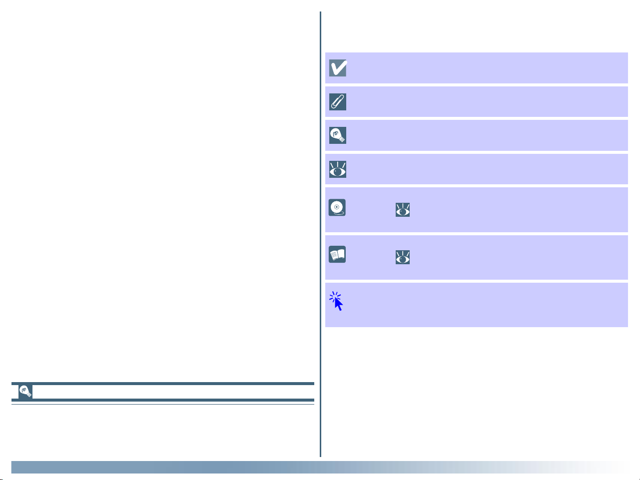
To make it easier to find the information you need, the following
symbols and conventions are used:
This icon marks cautions, information that you should read
before use to prevent damage to your Nikon scanner.
This icon marks notes, information that you should read
before using Nikon Scan.
This icon marks tips, additional information you may find
helpful when using Nikon Scan.
This icon indicates that more information is available elsewhere in this manual or in other documentation.
This symbol indicates that the cross-reference marked
with the icon is to the Nikon Scan 3 Reference Manual
(this manual).
This symbol indicates that the cross-reference marked
with the icon is to the hardware documentation provided with your scanner.
Blue text indicates a link to another part of this manual
or to the World-Wide Web. Click the text to follow the
link.
Printing This Manual
If desired, portions of this manual can be printed for ease of
reference using the Print… command in the Adobe Acrobat
Reader File menu.
Overview
2
Page 4

Terminology
Background Knowledge
Throughout this manual, “4000 ED” is used in reference to SUPER
COOLSCAN 4000 ED film scanners and “LS-2000” in reference to SUPER COOLSCAN 2000 film scanners. “MA-20 (S)”
is used in reference to both MA-20 and MA-20 (S) slide mount
adapters, “IA-20 (S)” in reference to both IA-20 and IA-20 (S)
adapters for APS (IX240) film (available separately), and
“SF-200 (S)” in reference to both SF-200 and SF-200 (S) slide
feeder adapters (available separately for 4000 ED and LS-2000
film scanners).
Illustrations
This manual is for use with both the Windows and Macintosh
versions of Nikon Scan. While the majority of the illustrations
are taken from the Windows version of the product, save where
otherwise noted the operations described apply to both the
Macintosh and Windows versions.
This manual assumes familiarity with operations common to
the Macintosh and Windows operating systems. If you are in
doubt about the meaning of any of the terms used here, refer to
the documentation provided with your operating system.
Life-Long Learning
As part of Nikon’s “Life-Long Learning” commitment to ongoing product support and education, continually-updated information is available on-line at www.nikon-euro.com. Visit this
site to keep up-to-date with the latest product information, tips,
answers to frequently-asked questions (FAQs), and general advice on digital imaging and photography.
Overview
3
Page 5

Getting Started
About This Chapter
Installing Nikon Scan
Before You Begin (pp. 5–6)
Installation (pp. 7–17)
This chapter takes you step-by-step through the process of installing Nikon Scan. Users who have already completed installation
can proceed directly to the next chapter for a tutorial covering basic scan operations.
Pg. For more information on:
152 Custom install
148 Uninstall
4
Page 6

Before You Begin
Before installing Nikon Scan, make sure that your computer system satisfies the following requirements:
System Requirements
Windows
CPU
OS
RAM
Hard-Disk Space
MMX Pentium 166 MHz or better (Pentium II or better recommended)
Windows 98 Second Edition (SE)*, Windows Me, Windows 2000 or later
32 MB (64 MB or more recommended)
†
20 MB free for installation with additional 20 MB available while Nikon Scan is running (200 MB
or more recommended, or 400 MB or more when using Digital ROC or Digital GEM)
Video Resolution 640 × 480 pixels or greater with 16-bit RGB color (high color) or more
IEEE 1394/Firewire
(4000 ED)
USB
(COOLSCAN IV ED)
SCSI (LS-2000,
COOLSCAN III)
Only boards compliant with Open Host-Controller Interface (OHCI) are supported**. If
your computer has an empty PCI slot and is not equipped with a suitable board, you can
install the board provided with the 4000 ED.
Only built-in USB ports are supported
**
Only boards compliant with the ASPI interface standard are supported
Miscellaneous CD-ROM drive required for installation
* The IEEE 1394 driver update provided with Nikon Scan is required when using the 4000 ED with Windows 98 SE.
† A minimum of 128 MB is recommended when using Digital GEM, Digital ROC, the optional IA-20 (S) APS (IX240) film adapter, or the optional
SA-30 roll-film adapter for the 4000 ED. Additional memory is required to run the host application when Nikon Scan functions as a TWAIN
source.
**The scanner may not function as expected when connected to an IEEE 1394/Firewire or USB hub.
Getting Started: Before You Begin
5
Page 7

Macintosh
CPU
OS
RAM
Hard-Disk Space
Power PC G3 or later (Power PC G4 or later recommended)
Mac OS 8.6 or later
24 MB (64 MB or more recommended)
*
20 MB free for installation with additional 20 MB available while Nikon Scan is running (200 MB
or more recommended, or 400 MB or more when using Digital ROC or Digital GEM)
Video Resolution 640 × 480 pixels or greater with 16-bit RGB color (thousands of colors) or more
†
IEEE 1394/Firewire
(4000 ED)
Firewire Support 2.3.3 or later recommended
Built-in ports supported from Firewire Support 2.0. If you are using an old-model (beige) G3
desktop computer not equipped with a Firewire board, you can install the board provided
with the 4000 ED.
USB
(COOLSCAN IV ED)
SCSI (LS-2000,
COOLSCAN III)
Only built-in USB ports are supported
Only boards compliant with Macintosh SCSI Driver 4.3 are supported
†
Miscellaneous CD-ROM drive required for installation
* A minimum memory allocation of 128 MB is recommended when using Digital GEM, Digital ROC, the optional IA-20 (S) APS (IX240) film adapter,
or the optional SA-30 roll-film adapter for the 4000 ED. Additional memory is required to run the host application when Nikon Scan functions
as an acquire plug-in.
† The scanner may not function as expected when connected to an IEEE 1394/Firewire or USB hub.
Getting Started: Before You Begin
6
Page 8
Installation
Installing Nikon Scan
Windows
If you are connecting your scanner for the first time, do not
connect the scanner until you have completed installation of Nikon
Scan. Follow the steps below to complete installation.
Step 1—Turn the computer on
Turn the computer on and wait for the operating system to
start up.
Click here to proceed to the next step.
If an earlier version of Nikon Scan is already installed on your
system, before upgrading to version 3 you will need to uninstall
the existing version of Nikon Scan. To uninstall Nikon Scan,
click the Start button and select the uninstaller from under
Nikon Scan in the Programs sub-menu.
Macintosh
Step 1—Turn the computer on
Turn the computer on and wait for the operating system to
start up.
Click here to proceed to the next step.
If an earlier version of Nikon Scan is already installed on your
system, before upgrading to version 3 you will need to uninstall
the existing version of Nikon Scan. To uninstall Nikon Scan,
insert the Nikon Scan CD into the CD-ROM drive and start the
installer. In the main install dialog, select Uninstall from the
pop-up menu at the top left corner of the dialog, then click the
Uninstall button to uninstall Nikon Scan.
Nikon Scan 3 offers full support for the scanners supported
under version 2.x. Users of Nikon Scan 2 can enjoy the improved functionality of Nikon Scan 3 while continuing to use
their existing scanners.
Getting Started: Installation
Nikon Scan 3 offers full support for the scanners supported
under version 2.x. Users of Nikon Scan 2 can enjoy the improved functionality of Nikon Scan 3 while continuing to use
their existing scanners.
7
Page 9
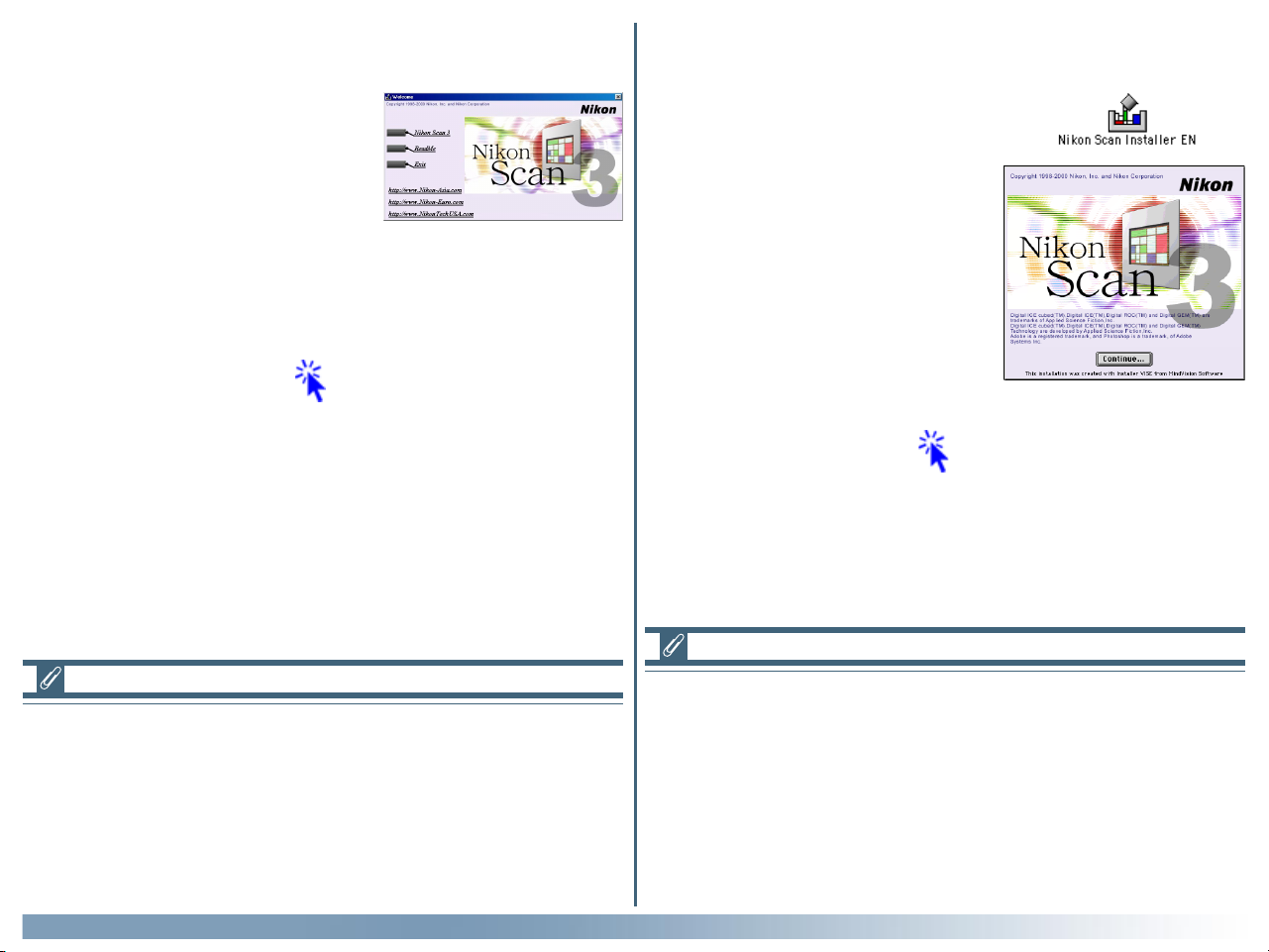
Step 2—Start the installer
Before starting installation of Nikon
Scan, quit any other programs that
may be running, including any viruschecking software. Insert the Nikon
Scan 3 CD into the CD-ROM drive.
After a pause, the Welcome dialog
shown at right will open automatically.
Click here to proceed to the next step.
Windows
Macintosh
Step 2—Start the installer
Before starting installation of Nikon
Scan, quit any other programs that
may be running, including any viruschecking software. Insert the Nikon
Scan 3 CD into the CD-ROM drive
and double-click the installer icon.
The window shown at right will be
displayed; click Continue….
Click here to proceed to the next step.
If the Welcome dialog does not appear when the CD-ROM is
inserted in the drive:
1. Double click the My Computer icon
2. In the My Computer window, click on the CD-ROM drive
icon with the right mouse button
3. Select Autorun from the menu that appears
Getting Started: Installation
Depending on where you purchased your scanner, the Nikon
Scan 3 CD will contain installers for from one to four language
versions of Nikon Scan: English (EN), French (FR), German (DE),
and Spanish (ES). Where installers for more than one language
version are available, the installers may be found in separate
folders; open the folder for the language of your choice and
double-click the installer icon.
8
Page 10
Windows
Step 3—Click Nikon Scan 3
Click Nikon Scan 3 to begin installation of Nikon Scan.
Click here to proceed to the next step.
The other links in the Welcome dialog are described below.
Link Description
Depending on where you purchased your
Other
software
scanner, one or more third-party software
packages may be bundled with Nikon Scan.
For information concerning installation and
use, see the manuals provided.
Macintosh
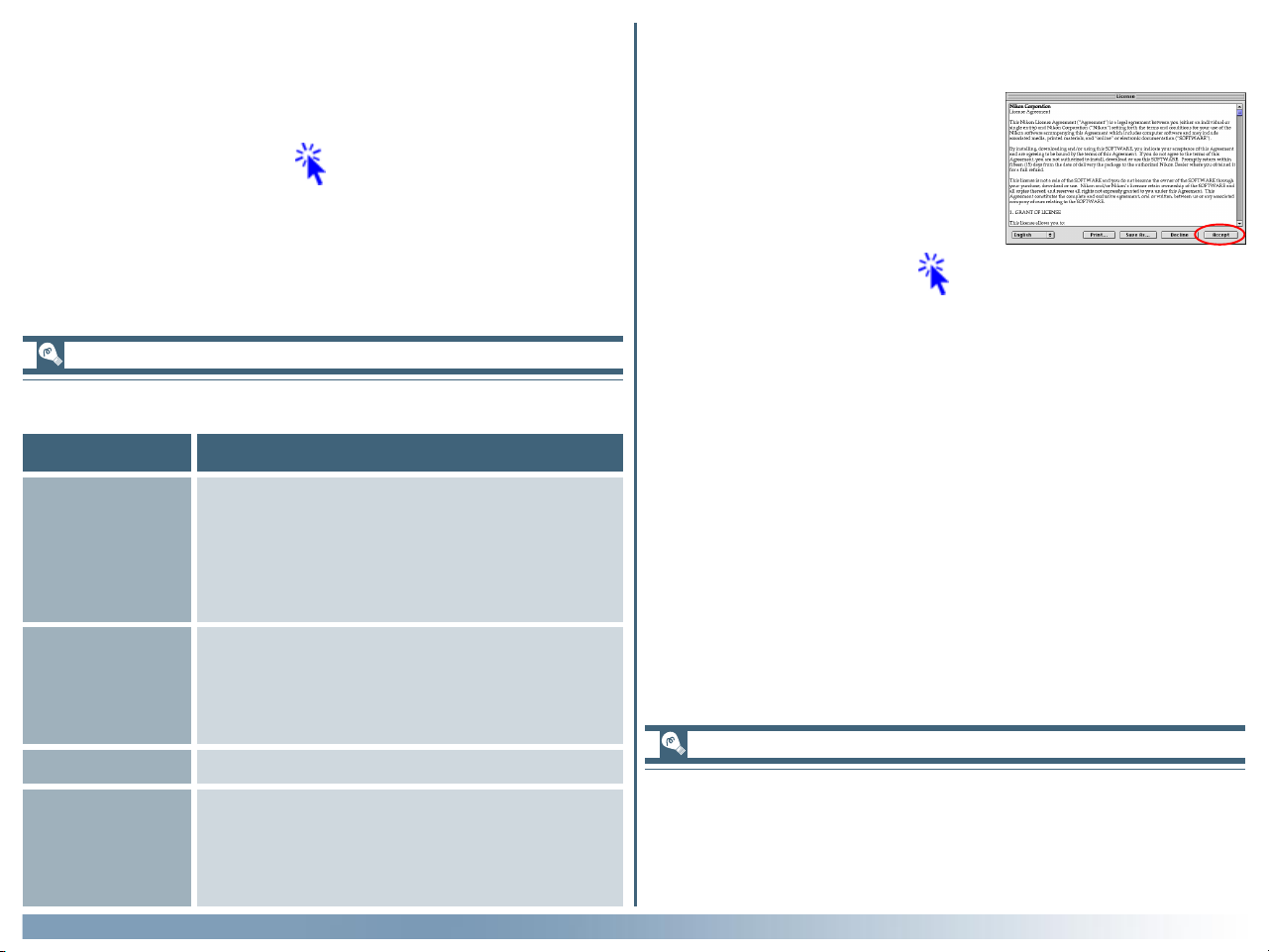
Step 3—Accept the license agreement
The software license agreement will
be displayed. After reading the agreement, click Accept to continue with
installation.
Click here to proceed to the next step.
Opens the ReadMe file, which may contain
ReadMe
information that could not be included in
the manual. Read this file before using
Nikon Scan.
Exit Exits the Welcome program.
Click to open your web browser to a
URL(s)
Nikon Digital Imaging web-site (your
computer must be set up for an Internet
connection).
Getting Started: Installation
To print the software license agreement (above) or the ReadMe
file described in Step 4, click Print…. Copies of these files are
stored on the Nikon Scan 3 CD in the same folder as the installer, where they can be accessed at any time.
9
Page 11
Windows
Step 4—Choose a language for Nikon Scan
Depending on where you purchased your scanner, you may be
prompted to select the language in which Nikon Scan’s menus
and dialogs will be displayed. Choose a language from the list
provided.
Macintosh
Step 4—Read the ReadMe file
After accepting the license agreement, take a few moments to
view the ReadMe file, which may contain important information
that could not be included in this manual. When you have finished, click Continue….
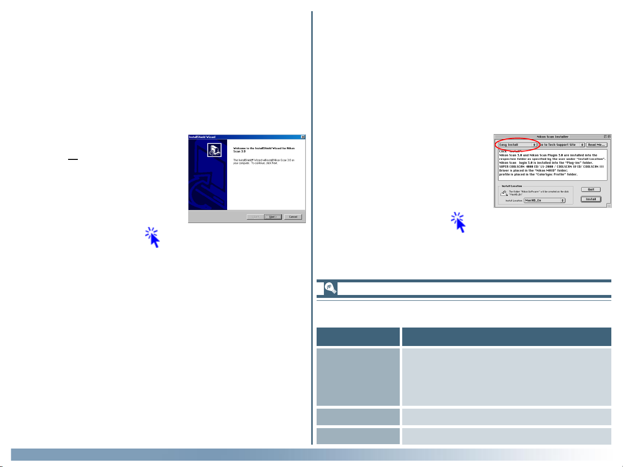
Step 5—Start the installation wizard
The dialog shown at right will be displayed; click Next to proceed to the
next step.
Click here to proceed to the next step.
Step 5—Select the installation type
The installer dialog shown at right will
be displayed. Select Easy Install
from the pop-up menu at the top left
corner of the dialog.
Click here to proceed to the next step.
The other options in the installer dialog are described below.
Button Description
Opens your web browser to the Nikon
Go to Nikon
Home Page
Digital Imaging web-site for your area
(your Macintosh must be set up for an
Internet connection).
Getting Started: Installation
Read Me… Opens the ReadMe file described in Step 4.
Quit Quits the installer.
10
Page 12
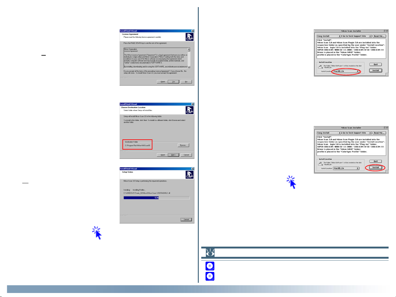
Step 6—Accept the license agreement
The software license agreement will
be displayed. After reading the agreement, click Ye s to continue with installation.
Step 7—Choose a location for Nikon Scan
The default location for Nikon Scan
is shown in the Destination Folder
text box in the Choose Destination
Location dialog. To install Nikon Scan
to a different folder, click Browse and
navigate to the desired location.
After selecting a destination folder,
click Next to begin installation. The
dialog shown at right will be displayed
while installation is in progress.
Windows
Macintosh
Step 6—Choose a location for Nikon Scan
The disk and folder to which Nikon
Scan will be installed (by default, the
root directory on the system disk)
are shown in the Install Location
panel. Choose a new disk from the
Install Location pop-up menu, or
choose Select Folder… to navigate
to the desired location.
Step 7—Click Install
Click Install in the installer dialog to
begin installation. A progress indicator will be displayed while files are
copied to your hard disk.
Click here to proceed to the next step.
Click here to proceed to the next step.
Getting Started: Installation
Pg. For more information on:
152 Custom install
148 Uninstall
11
Page 13
Windows/Macintosh
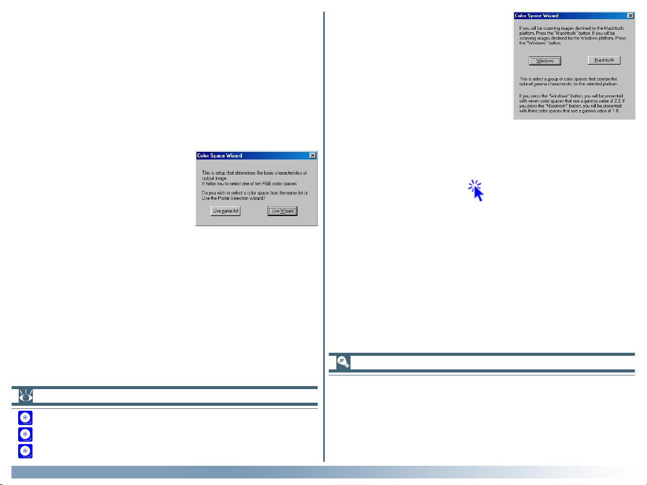
Step 8—Select an RGB profile
When images are scanned in RGB, Nikon Scan uses calibrated
RGB profiles to ensure consistent color reproduction. As part
of the installation process, you can choose which of these profiles will be used as the default for the calibrated RGB color
space when you first start Nikon Scan. A new profile can be
chosen at any time from the Nikon Scan Preferences dialog.
8-1 Once the Nikon Scan program
files have been installed, a dialog
similar to that shown at right will
be displayed.
To choose a profile from a list, click Use name list and
proceed to Step 8-4. To choose a profile with the help of a
Wizard, click Use Wizard and proceed to Step 8-2. If you
are unsure as to what color-space profile to choose, we
recommend that you select Use Wizard and choose the
profile suggested for your platform. A new profile can be
chosen at any time after installation in the Nikon Scan Preferences dialog.
8-2 The Color Space Wizard opens
with the dialog shown at right.
Choose Windows if the majority of the images that you
scan will be edited on Windows platforms, or Macintosh
if you do most of your editing on a Macintosh.
Click here to proceed to the next step.
“Profile”
Pg. For more information on:
105 Preferences
115 Color-space profiles
107 Nikon Color Management System
Getting Started: Installation
To ensure accurate color reproduction, the Nikon Color Management System (Nikon CMS) must have information about the
color characteristics of your scanner, monitor, and the color
space used when editing or printing images. This information is
contained in files called “profiles.”
12
Page 14
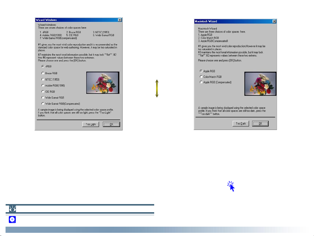
8-3 Depending on your choice, you will be presented with one of the dialogs shown below.
Narrow gamut: vivid,
“saturated” colors
Wide gamut: low-
contrast, “flat” colors
Windows profiles Macintosh profiles
(gamma 2.2) (gamma 1.8)
Choose a profile from the list (sRGB is recommended for images destined for Windows computers, Apple RGB for the
Macintosh). The effects of the color range and gamma value for each profile can be previewed in the image to the right of the
list. If the image seems too dark or too bright, click Too dark to choose from a list of Windows profiles, or Too light to
choose from a list of Macintosh profiles. Click OK to choose the selected profile as the initial RGB color space.
Pg. For more information on:
72 Gamma and color range (gamut)
Getting Started: Installation
Click here to proceed to the next step.
13
Page 15
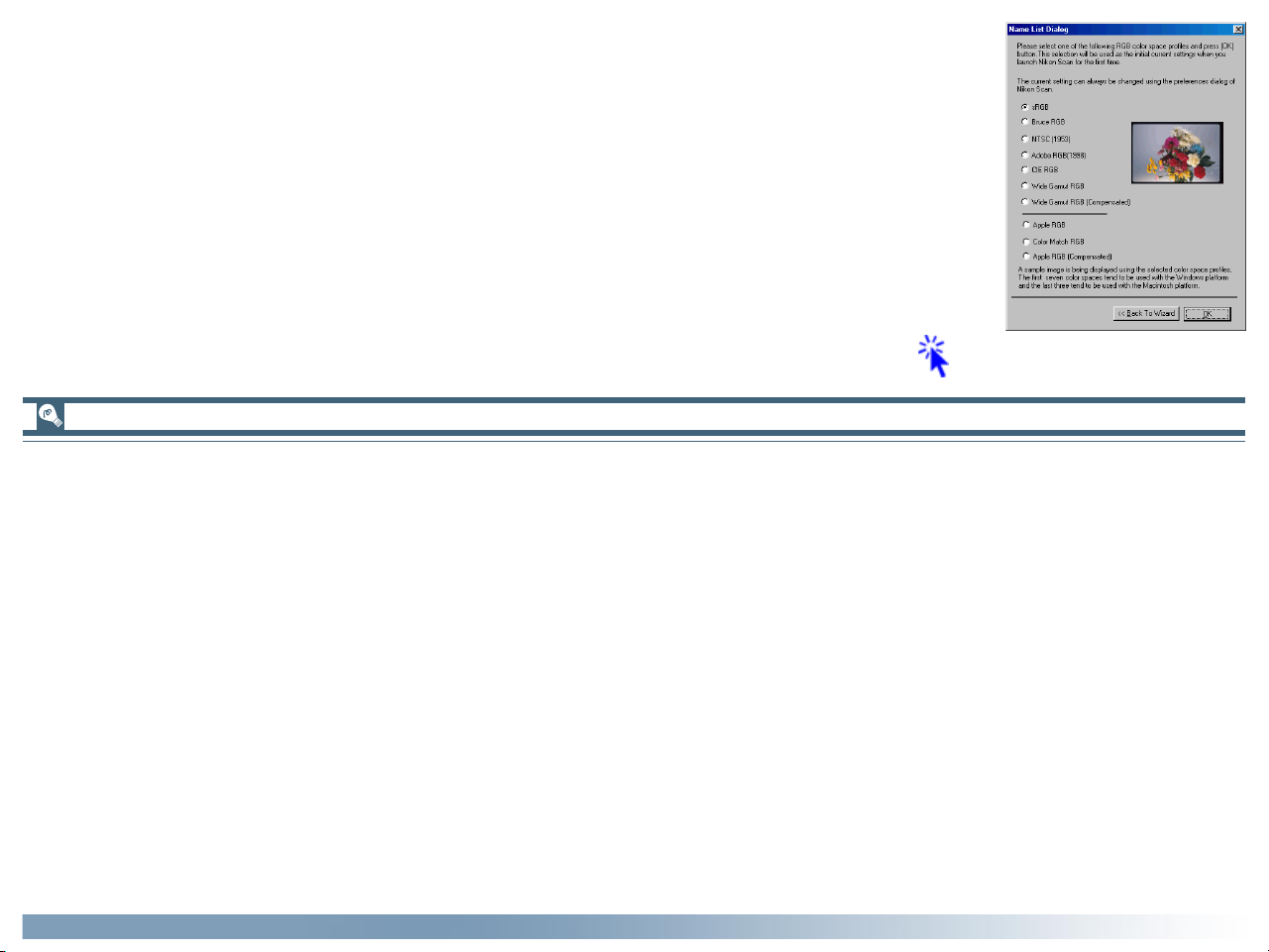
8-4 A list of ten RGB color-space profiles will be displayed. Choose a profile for use as the initial
calibrated RGB color space. The effects of the color range and gamma setting for each profile can
be seen in the image to the right of the profile list. Select a profile and click OK. If you are not
sure which profile is right for you, click Back to Wizard to open the Wizard dialog shown in Step
8-3.
Click here to proceed to the next step.
Choosing the profile that is right for you
When choosing a profile for the RGB color space, you should bear two things in mind: the gamma value for your platform and the
gamut (range) of colors required for the task at hand.
Gamma is a fundamental characteristic of imaging systems, used to adjust the brightness of scanned images so that they display
correctly on your monitor. The first seven profiles in the profile list have a gamma value of 2.2, which is the de facto standard for
Windows. The last three have a gamma value of 1.8, the default value for the Macintosh. Select a profile appropriate to the
platform on which the image is to be displayed.
The other factor to bear in mind when selecting a profile is the gamut, or range of colors you will need for the task at hand. If you
are not planning to make fine adjustments to color, a profile with a narrow range of colors is suitable. Note, however, that a
narrow gamut may produce colors that are too “saturated,” or vivid. If you intend to fine-tune color, contrast, and brightness using
an editing tool such as the Curves palette, choose a profile that offers a wide range of colors. Without editing, however, such a
profile may produce “flat,” low-contrast images.
Profiles within each of the two groupings are ordered by the size of their gamut. Those with a narrow gamut are listed at the top,
those with a wide gamut at the bottom.
Getting Started: Installation
14
Page 16
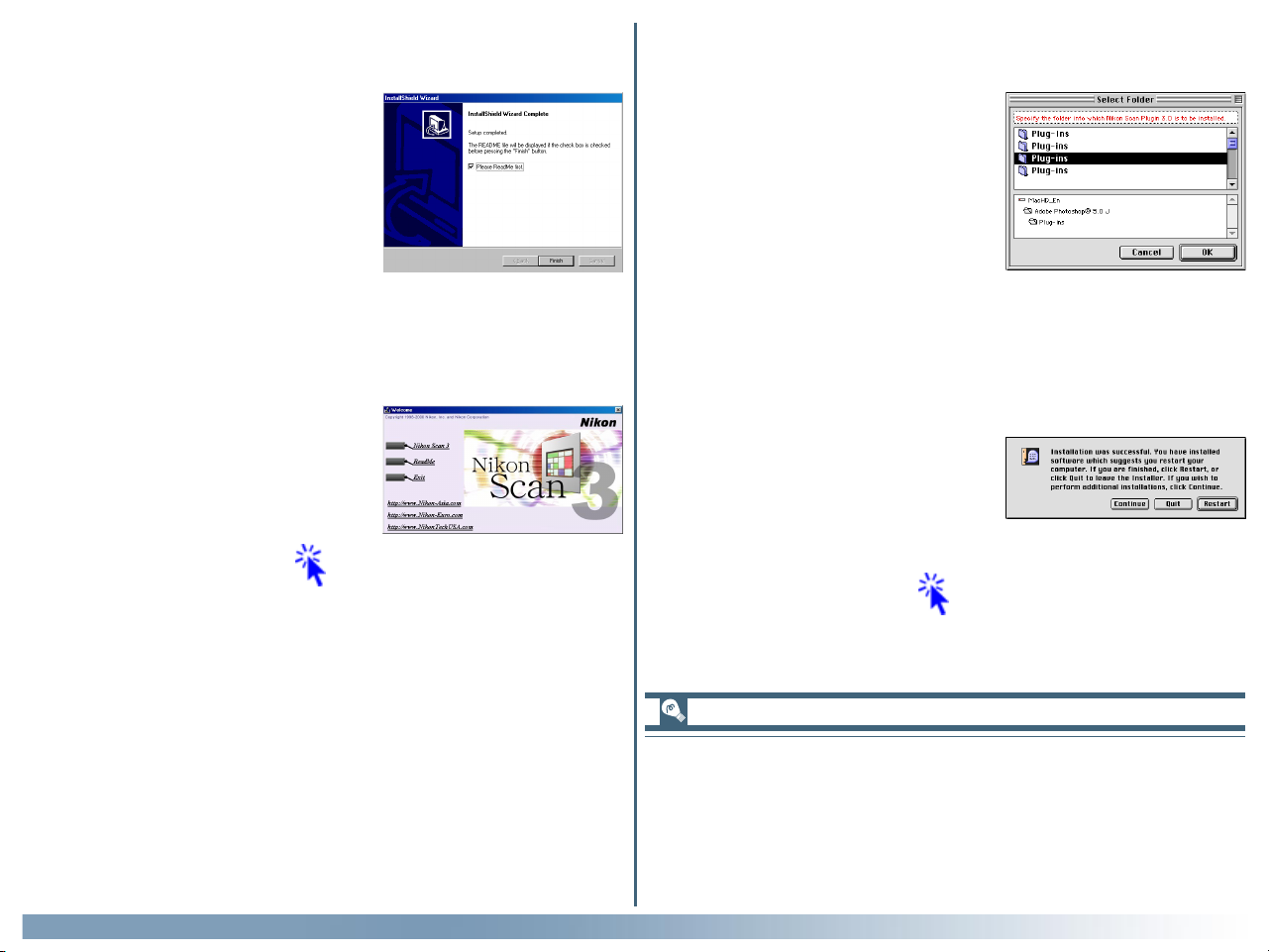
Step 9—Read the ReadMe file
When installation is complete, the
dialog shown at right will be displayed.
Confirm that Please ReadMe first
is checked and click Finish to display the ReadMe file. Take a few moments to view this file, which may
contain information that could not be
included in this manual.
Step 10—Quit the installer
Closing the ReadMe file returns you
to the Welcome dialog. Click Exit
to return to Windows.
Click here to proceed to the next step.
Windows
Macintosh
Step 9—Select a plug-ins folder
To scan images using a third-party
application, you will need to install a
copy of the Nikon Scan plug-in in the
application’s plug-in folder. The installer will automatically locate the
plug-in folders on your computer and
display them in the dialog shown at
right. Select the plug-ins folders for
the desired applications and click OK.
Step 10—Quit the installer
The dialog shown at right will be displayed when installation is complete.
Click Restart to restart your computer.
Click here to proceed to the next step.
Getting Started: Installation
The installer saves a copy of the Nikon Scan plug-in in a plug-ins
folder under the folder to which you installed Nikon Scan. To
use the plug-in with another application, first make sure that the
application is not running and then copy the plug-in to the
application’s plug-in folder.
15
Page 17
Windows
Step 11—Check that the Nikon Scan CD is in place
If you will be connecting your scanner for the first time, before
you will be able to use the device you will need to register it
with the Windows Device Manager. Before proceeding to the
next step, make sure the Nikon Scan 3 CD is inserted in the
CD-ROM drive, and then click here to proceed to the next
step.
If you have already registered your scanner with Windows, either because you are re-installing Nikon Scan or are a user of a
LS-2000 or COOLSCAN III film scanner who is upgrading to
Nikon Scan 3, installation is complete. Click here to view
the next chapter.
Macintosh
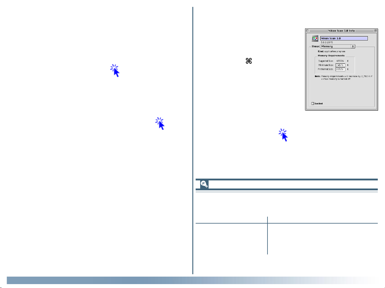
Step 11—Check the memory available to Nikon Scan
Locate the Nikon Scan 3.0 icon in
the location you chose in Step 6. A fter clicking the icon once to select it,
choose Get Info ( I) from the Finder
File menu. Select Memory from the
Show pop-up menu in the information
dialog to display memory requirements
as shown at right. If possible, enter a
value for “Preferred size” greater than
or equal to the suggested size.
Click here to proceed to the next step.
Memory requirements for the Macintosh
Getting Started: Installation
Memory requirements vary with the adapter used. The following minimum allocations are recommended:
Adapter Preferred Size
MA-20 (S) 65,536 K (64 MB)
SA-21/SA-20 65,536 K (64 MB)
IA-20 (S) 131,072 K (128 MB)
SA-30 131,072 K (128 MB)
* A minimum allocation of 128 MB is recommended when using Digital ROC
or Digital GEM.
*
16
Page 18
Windows
Step 12—Connect the scanner
Connect the device as described in the hardware documentation. If you are using the LS-2000 or COOLSCAN III, be sure to
turn the computer off before connecting the device. If you are
using a scanner with an IEEE 1394/Firewire or USB interface,
such as the 4000 ED or COOLSCAN IV ED, you can leave the
computer on while connecting the scanner. Note, however, that
if you are using the 4000 ED under Windows 98 Second Edition,
you will need to install the IEEE 1394 driver update provided
with Nikon Scan before connecting the scanner.
Step 13—Turn the scanner on
Turn the scanner on. If you are using a scanner with a SCSI
interface, such as the LS-2000 or COOLSCAN III, after turning
the scanner on turn on the computer and start Windows.
Step 14—Register the scanner with Windows
The registration process differs depending on the scanner and
operating system used. Click here for step-by-step instructions on registering your scanner.
Macintosh
Step 12—Connect the scanner
Connect the device as described in the hardware documentation. If you are using the LS-2000 or COOLSCAN III, be sure to
turn the computer off before connecting the device. If you are
using a scanner with an IEEE 1394/Firewire or USB interface,
such as the 4000 ED or COOLSCAN IV ED, you can leave the
computer on while connecting the scanner.
Step 13—Turn the scanner on
Turn the scanner on. If you are using a scanner with a SCSI
interface, such as the LS-2000 or COOLSCAN III, after turning
the scanner on turn on the computer and start Windows.
Installation is now complete. Click here to view the next
chapter.
Once you have registered your scanner, installation is complete.
Click here to view the next chapter.
Pg. For more information on:
A–1 IEEE 1394 driver update for Windows 98 SE
Getting Started: Installation
To check whether Mac OS recognizes the scanner, use the Apple
System Profiler in the Apple menu.
17
Page 19

Tutorial
Basic Scanning
The Scan Window (pp. 19–25)
Making a Scan (pp. 26–35)
About This Chapter
This chapter:
• Introduces you to the scan window, the scanner control center
• Takes you step-by-step through the process of making a scan
This chapter provides enough information to enable you to scan images and open them in another application or save them to
disk. More information on scanning, image processing, and preferences is included in the following chapters.
18
Page 20

The Scan Window
The Nikon Scan Plug-in or TWAIN Source
Nikon Scan consists of the following two modules:
• The Scan Window
The scan window is the interface between your scanner and
the imaging application that acts as a host for Nikon Scan. It
is where you adjust scanner settings and perform image enhancement before scanning the image into the host application, which can be any application that supports TWAIN
(Windows) or Adobe Photoshop 5.0 plug-ins (Macintosh).
• The Nikon Scan Applet
The Nikon Scan applet, or mini-program, serves as a host for
the scan window when no other compatible program is available, or when you don’t have the resources needed to run a
more sophisticated imaging program. When you are using
the Nikon Scan applet, Nikon Scan is said to be functioning
as a “stand-alone” application.
This section describes how to access the scan window and introduces you to scan window controls.
Installing Photoshop 5.0 LE
Windows: After inserting the Photoshop LE CD into the CD-ROM drive, double-click in turn
on the My Computer and CD icons, open the Photosle folder in the folder for the language
of your choice, and double-click Setup.exe. The serial number can be found on the userregistration card in the CD-ROM case.
Macintosh: After inserting the Photoshop LE CD into the CD-ROM drive, double-click the
CD-ROM icon on the desktop, open the Photoshop 5.0 LE folder in the folder for the
language of your choice, and double-click the installer icon. The serial number can be found on
the user-registration card in the CD-ROM case.
Tutorial: The Scan Window
Opening the Scan Window
Before opening the scan window, make sure that your Nikon
scanner is connected and powered on.
• Opening the Scan Window from a Host Application
To open the scan window from a third-party application such
as Adobe Photoshop, select Nikon Scan from the host’s import or acquire menu (see the host application manual for
details). If you are using a Macintosh, the Nikon Scan 3.0 plugin must first be copied to the application’s Plug-ins folder. In
the Windows version of Adobe Photoshop LE, the File menu
contains a sub-menu of import commands which in-cludes
an option for selecting the TWAIN source; select this option
and choose “Nikon Scan 3.0” from the list of sources that
appears. In the Macintosh version, the scan window can be
opened by choosing “Nikon Scan 3.0” from the sub-menu of
import/export plug-ins under the File menu.
• Using Nikon Scan as a Stand-Alone Application
Double-click the Nikon Scan 3.0 icon in the folder to which
you installed Nikon Scan. Windows users can also start Nikon
Scan by clicking the Windows Start button and selecting
Nikon Scan 3.0 from the Programs sub-menu.
Pg. For more information on:
90 Starting the Nikon Scan applet
19
Page 21
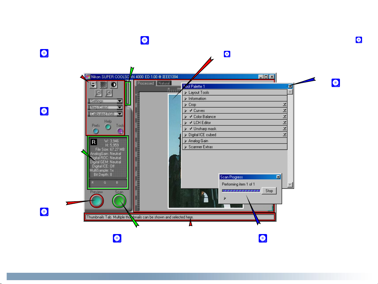
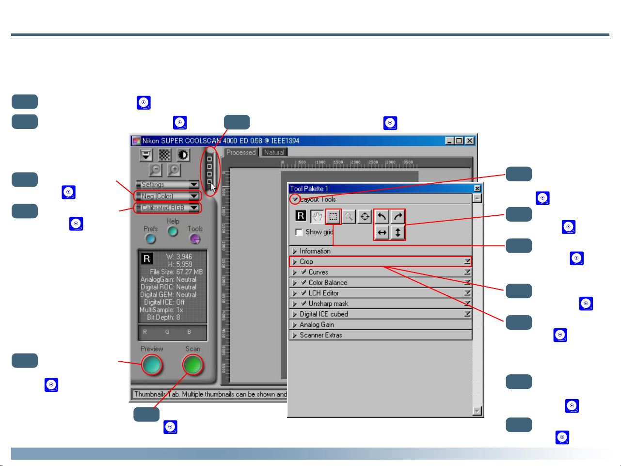
Getting to Know the Scan Window
Take a few moments to familiarize yourself with scan window controls.
Thumbnail drawer tab
Control area
(see 21)
Contains the most frequently
used scanning and preview controls, including the film eject
button and media type and
color-model menus.
Information panel
(see 22)
Indicates:
• whether the image has been
flipped or rotated
• the physical dimensions and
file size of the portion of the
image to be scanned
• what extra processing will be
performed when the image is
scanned
• the color values for the pixel
under the cursor
Preview button
(see 23)
Click to preview the frame to be
scanned. The preview shows
how the image will look when it
is scanned.
Click to select frames to be scanned from multi-frame
film (this tab is not displayed when the MA-20 (S) or
SF-200 (S) is inserted in the scanner).
Scan button
(see 23)
Click to scan the selected
portion of the image into
the host application.
(see 23)
Interactive help
Gives a brief tip about the
control under the mouse
cursor.
Preview area
The preview image is displayed here. Click the Natural tab (see 23)
to see how the image looked before processing; click the Processed tab
(see 23) to see how the image will look when it is scanned.
Tool chest
(see 24)
Contains tools for:
• setting the image orientation
and choosing the portion of
the image to be scanned
• controlling the physical dimensions and file size of the
image when opened in the
host application
• enhancing color, contrast,
and sharpness before the
image is scanned and, when
Nikon Scan is used as a standalone application, after images are opened in the Nikon
Scan applet
• removing the effects of
scratches, dust, fading, and
film grain
• controlling the exposure values for the scanning element
Scan Progress window
(see 23)
Shows what actions are being performed, and gives a
log of automated tasks.
and other features particular
to your scanner
Tutorial: The Scan Window
20
Page 22
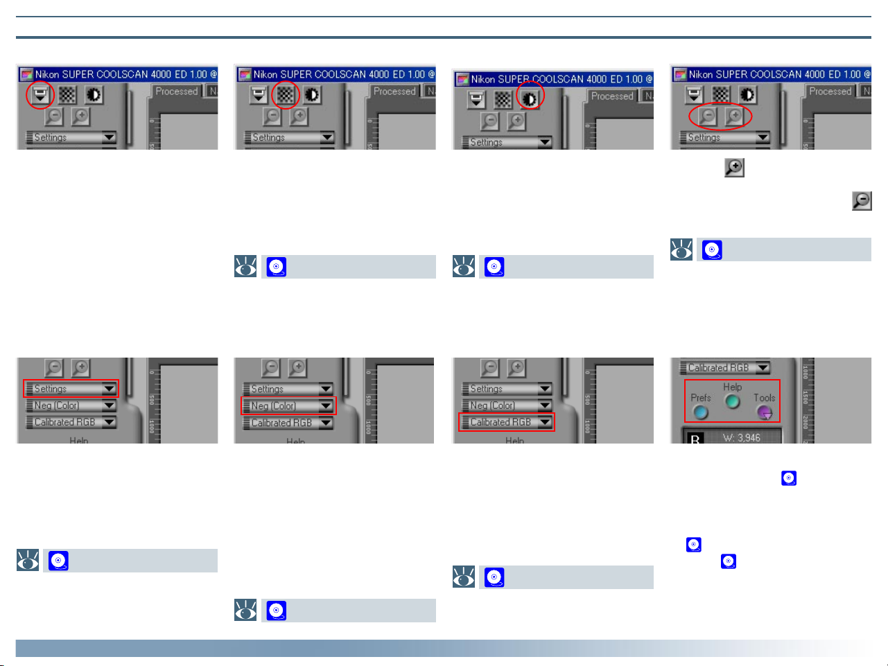
The Control Area
Eject Button
Autofocus Button Autoexposure Button Zoom Buttons
Ejects film from multi-frame adapters (this button is disabled when the
MA-20 (S) slide-mount adapter is in
place). Control-click (Windows) or
option-click (Macintosh) to eject a
slide from the optional SF-200 (S)
slide feeder without feeding a new
one.
Click to focus the scanner on the
selected point of the image, or control-click (Windows) or option-click
(Macintosh) to select a new focus
point.
38
Before scanning, the scanner needs
to gather information about the image to adjust exposure for best results. Click this button to adjust
exposure.
39
Click the button to zoom in on
the current crop, enlarging it to fill
the preview area. Click the
button to zoom out.
33
Settings Menu Media Type Menu Color Model Menu Window Buttons
Using the options in this menu, you
can reset the scanner to default settings, or save scanner settings suited
to particular scanning conditions and
recall them as desired.
88
Adjusts scanner settings to match
the media in the scanner. Select
positive when scanning film positives
(slides, reversal film, or monochrome
positives), negative (color or monochrome) when scanning negatives. A
separate option is available for scanning Kodachrome positives.
Select a color model according to
the capacities of your image editing
software and whether the image is
destined for output on a commercial
four-color printing press or display
on a monitor.
28
• Prefs: click to open the prefer-
ences dialog (see 105)
• Help: click to open the Nikon
Scan help file
• Tools: open the Tool Chest
( 40) or Scan Progress win-
dows ( 31).
Tutorial: The Scan Window
27
21
Page 23
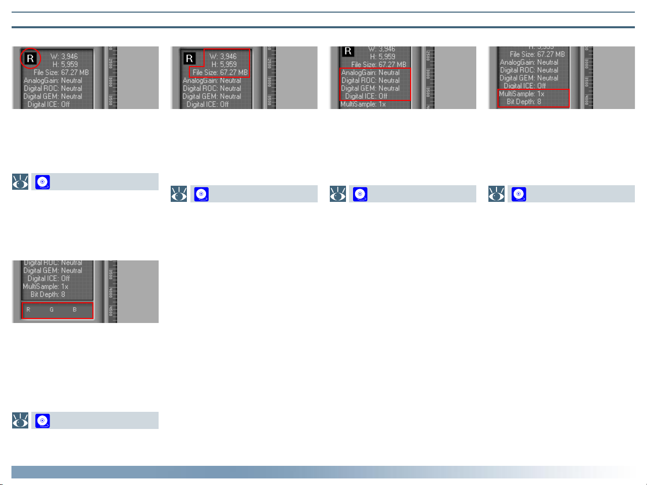
The Information Panel
Orientation
Dimensions/File Size Image Enhancement Scanner Extras
Shows the orientation of the preview image relative to the original,
reflecting any flips or rotations that
have been performed.
44
Color Values
Gives the color values for the pixel
under the cursor. After processing,
two values appear, one reflecting the
color in the Natural tab (top row),
the other the color in the Processed
tab (bottom row).
Gives the height and width of the
current crop in pixels, and the size of
the file that will result if the crop is
scanned at current output size and
resolution.
46
Indicates whether Digital ICE3 and
analog gain are in effect. Remember
to use Digital ICE3 only when needed,
as turning these features on can substantially increase scanning times.
51
Indicates the current bit depth (which
determines the maximum number of
colors in the image) and whether
multi-sample scanning (4000 ED and
LS-2000 only) is in effect.
57
63
Tutorial: The Scan Window
22
Page 24
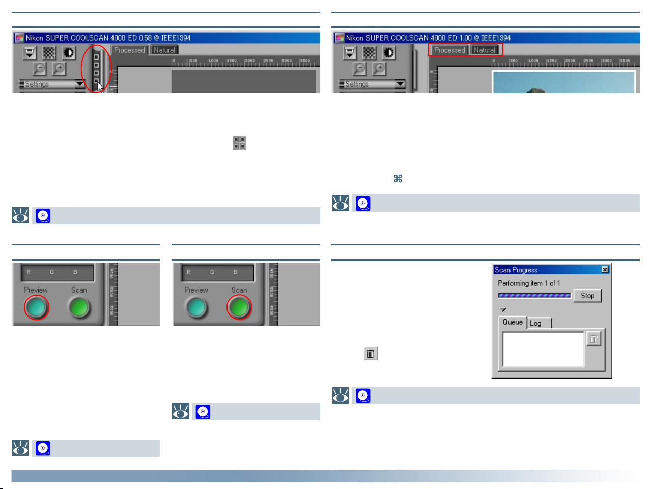
The Thumbnail Drawer Tab
The Natural/Processed Tabs
This tab is only displayed when a multi-frame adapter is inserted in the
scanner. Clicking this tab opens the thumbnail drawer, where you can select
the frame to be scanned by clicking the associated frame number. To view
the frames as small previews (thumbnails), click the button. Multiple
frames can be selected by clicking each frame in turn while holding down the
control (Windows) or command (Macintosh) key, or by holding down the
shift key while clicking two frames to select these frames and all the frames
between them.
29
The Preview Button The Scan Button
Clicking this button displays a preview of the image to be scanned (if
multiple frames are selected in the
thumbnail drawer, a preview will be
performed for each frame). You will
need to create a new preview after
changing the media type or using the
zoom buttons.
Scans the image and opens it in the
host application (if multiple frames
are selected in the thumbnail drawer,
each frame will be scanned and
opened in a separate window).
35
These tabs allow for a quick “before-and-after” comparison showing the
effects of processing. The Natural tab shows how the image looked before
processing, the Processed tab how the image will look when scanned at
current settings. If you are using Nikon Scan as a stand-alone application, you
can switch back and forth between the tabs using the Show Natural Pane/
Show Processed Pane commands in the View menu or the Ctrl-T
(Windows) or -T (Macintosh) keyboard shortcuts.
31
The Scan Progress Window
This window shows the progress of
preview and scan operations. The
current task can be cancelled by
clicking the Stop button. Tasks that
have yet to be performed are listed
in the Queue tab and can be cancelled by selecting the task and clicking the icon. Completed tasks
are listed in the Log tab.
31
31
Tutorial: The Scan Window
23
Page 25
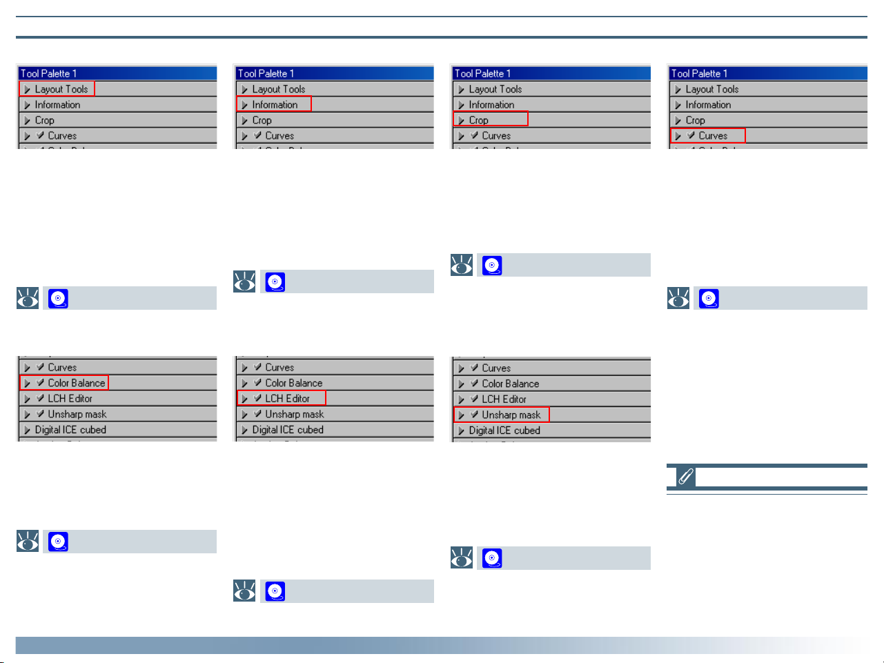
The Tool Chest
Layout Tools
*
Information
*
Crop
†
Curves
*
Use these tools to select the portion
of the image to be scanned (the
“crop”) and to rotate and flip the
image prior to scanning. You can
also select a new focus area and
scroll images that have been opened
in Nikon Scan after scanning.
43
Color Balance
Use the color balance tools to make
adjustments to brightness, contrast,
and color balance that affect the
entire image.
76
Tutorial: The Scan Window
*
Gives height and width of the current crop and the coordinates of its
top left corner. The color value
display shows the color of the pixel
under the cursor before and after
processing.
45
*
78
LCH Editor
Like the Curves too, the LCH editor
can be used to adjust brightness and
contrast in shadows, mid-tones, and
highlights. It also incorporates hue
and chroma editors, which provide
extremely flexible tools for adjusting
color.
This is where you adjust the resolution and size of the image according
to the output device (printer or
monitor) on which the image will be
displayed.
46
Unsharp Mask
Unsharp mask increases the sharpness of the image by making edges
more distinct, either over the entire
image or in areas where specific colors are prominent.
85
*
One of three color editing tools
offered by Nikon Scan, the curves
tool is useful when adjusting contrast
and making changes to color balance
that effect only a specific portion of
the tone range (shadows, mid-tones,
or highlights).
63
Tools marked with an asterisk (“*”)
are available both in the scan window
and (where Nikon Scan is used as a
stand-alone application) when images are opened in the Nikon Scan
applet after scanning. Those marked
with a “†” are only available in the
scan window.
24
Page 26
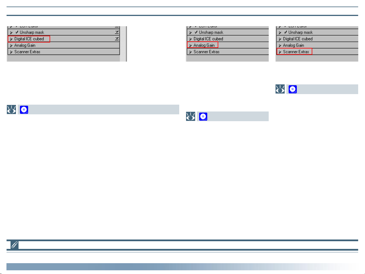
The Tool Chest (Continued)
Digital ICE Cubed (Digital ICE3)
†
Analog Gain
†
Scanner Extras
†
Depending on your scanner, up to three image enhancement tools are
available:
• Digital ICE: reduces the effects of dust and scratches
• Digital ROC: restores colors lost through fading
• Digital GEM: reduces the effect of film grain
51
This tool allows exposure for the
colored elements in the scanner’s
light source to be adjusted manually.
Use when you want to change exposure from the values produced by
the autoexposure operation.
56
These tools offer you control over
features specific to your scanner.
57
Tools marked with a “†” are only available in the scan window.
Tutorial: The Scan Window
25
Page 27
Making a Scan
The Basics
This section covers the basics of making a scan, from opening the scan window to scanning an image into the host application. A
detailed description of Nikon Scan’s color editing and image enhancement features may be found in the following chapter.
STEP 1Open the scan window ( 27)
STEP 2Insert the medium in the scanner ( 27)
STEP 3Select the media
type ( 27)
STEP 4Select the color
model ( 28)
STEP 6Preview the frames
to be scanned
( 31)
STEP
Scan the images
13
( 35)
Tutorial: Making a Scan
STEP 5Select the frames to be scanned ( 29)
STEP 7Open the Layout
Tools palette
( 32)
STEP 8Adjust image orien-
tation ( 32)
STEP 9Select the area to be
scanned ( 33)
STEP
Select an output
10
resolution ( 34)
STEP
Adjust the output
11
size ( 34)
STEP
Adjust settings for
12
the remaining
frames ( 35)
STEP
Save the scanned im-
14
ages ( 35)
26
Page 28
Before making a scan, connect the scanner and turn it on as
described in the scanner manual. You will also need to turn on
your computer and wait for the operating system to start up.
Option When to use it
Positive
Use when scanning most makes of
positive slides or reversal film.
Step 1—Open the scan window
Open the scan window as described in the previous section
under “Opening the Scan Window.”
Step 2—Insert the medium in the scanner
Insert the medium to be scanned in the scanner as described in
the hardware documentation.
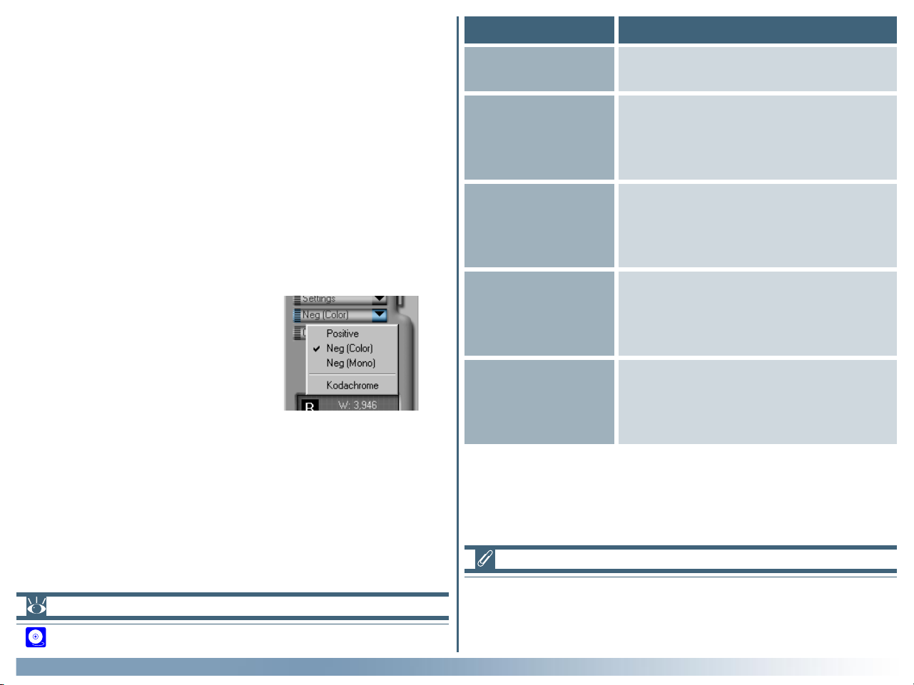
Step 3—Select the media type
Select the media type from the popup menu in the control area. The
options available depend on the selected scanner.
Neg (Color)
(4000 ED/
COOLSCAN IV ED
only)
Neg (Mono)
(4000 ED/
COOLSCAN IV ED
only)
Negative
(LS-2000/
COOLSCAN III
only)
Kodachrome
(4000 ED/
COOLSCAN IV ED
only)
Use when scanning color film negatives.
Use when scanning black-and-white
negatives.
Use when scanning film negatives.
Use when scanning Kodachrome
positives.
Pg. For more information on:
19 Opening the scan window
Tutorial: Making a Scan
Select Positive when scanning AGFA SCALA monochrome film,
or when scanning prepared microscope slides using the FH-G1
medical slide holder (available separately).
27
Page 29
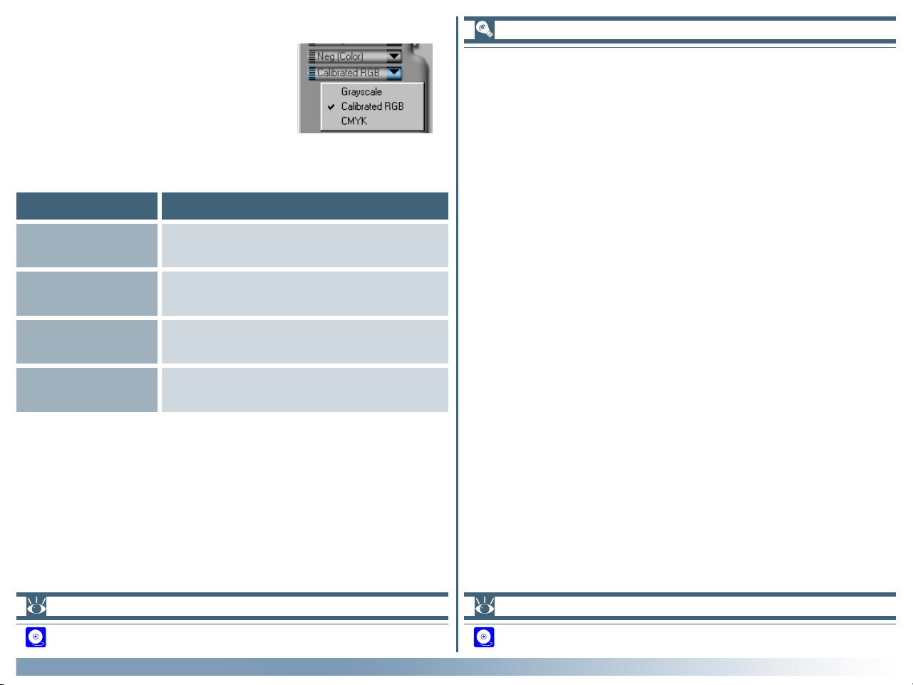
Step 4—Select the color model
Select a color model according to
how you intend to use the image. The
options available depend on whether
the Nikon Color Management system
(CMS) is on (the default setting) or
off.
Option When to use it
Grayscale
Use for images that will be printed or
displayed in monochrome
Nikon Color Management
The Nikon Color Management system (CMS) ensures that the
colors from your scanner are reproduced accurately on different output devices such as printers and monitors. Accuracy is
ensured by means of ICC profiles that provide information about
the color space used for scanning and the characteristics of the
video system, printer, or monitor. Profiles are available for RGB
(for use when editing images or displaying them on a monitor)
and CMYK (for professionals who wish to create a file ready for
printing on a commercial four-color printing press).
Calibrated RGB
(CMS on)
CMYK
(CMS on)
RGB
(CMS off)
Use for images that will be edited or
displayed on a computer monitor
Use for images destined for output on a
four-color printer
Use to edit raw RGB data from the
scanner
Pg. For more information on:
107 Turning Nikon CMS on and off
Tutorial: Making a Scan
Pg. For more information on:
107 Nikon Color Management
28
Page 30
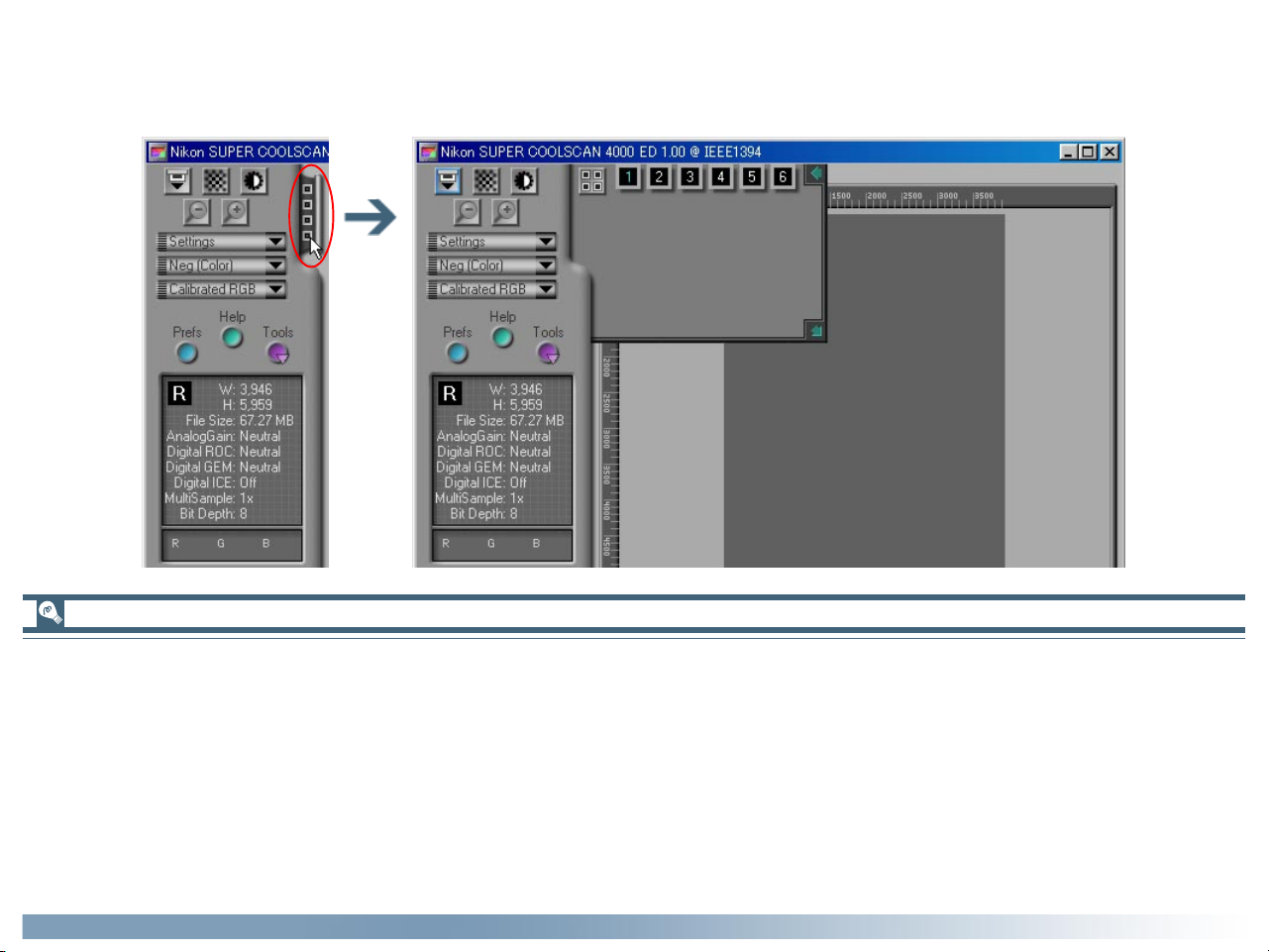
Step 5—Select the frames to be scanned
If you are using a multi-frame adapter, you can select the frames to be scanned from the thumbnail drawer. Click the thumbnail
drawer tab to open the drawer as shown below.
Multi-frame adapters
A multi-frame adapter is an adapter that allows you to scan more than one frame of a film roll or strip film without having to
remove the media from the adapter between scans. The following multi-frame adapters are available for the Nikon scanners
supported under Nikon Scan 3:
• the SA-21 (4000 ED/COOLSCAN IV ED) and SA-20 (LS-2000/COOLSCAN III) strip-film adapters
• the IA-20 (S) adapter for APS (IX-240) film (sold separately)
• the SA-31 film-roll adapter for the 4000 ED (sold separately)
• the SF-200 (S) slide feeder for the 4000 ED and LS-2000 (sold separately; note that because the SF-200 (S) can preview only
one frame at a time, the thumbnail drawer is not available when this adapter is in use)
Tutorial: Making a Scan
29
Page 31

By default, frames are identified by number only. To view a small
preview image (thumbnail) for each frame, click the button.
The button icon will change to ; click the button again to
return to a frame number display.
The frame to be scanned can be selected by clicking the associated frame number or thumbnail. To select multiple frames,
click each frame in turn while holding down the control (Windows) or command (Macintosh) key, or hold down the shift key
while clicking two images to select the images and all frames
between them.
Thumbnail drawer controls
• To hide the thumbnail drawer: click the button at the
top right corner.
• To adjust the size of the thumbnail drawer: drag the
bottom right corner (the thumbnail drawer can not be made
larger than the scan window).
If the thumbnails don’t fit in the frame, use the Strip Film Off-
set control in the Scanner Extras palette to adjust their position.
Tutorial: Making a Scan
When film is inserted in the SA-21 strip-film adapter for 4000 ED/
COOLSCAN IV ED film scanners, six frame numbers will be
displayed in the thumbnail drawer regardless of the number of
frames in the film. Similarly, when film is inserted in the optional
SA-30 roll-film adapter for 4000 ED film scanners, forty frame
numbers will be displayed regardless of the number of frames in
the film. The correct number of frames will be displayed when
the button is clicked to create thumbnail previews.
30
Page 32

Step 6—Preview the frames to be scanned
Click the Preview button. A pre-
view of the image to be scanned will
appear in the Natural and Processed
tabs to the right of the control area.
The Scan Progress window
While scanning is in progress, the
progress window will show the operation currently being performed.
The current task can be cancelled by
clicking the Stop button.
To view operations that have yet to
be performed, first click the triangle
under the progress meter, then click
the Queue tab to display the Queue
sheet listing unfinished tasks. Tasks
can be cancelled by selecting the desired operation(s) and clicking the
icon.
Completed tasks are listed in the Log
sheet.
If you are using a multi-frame adapter, a preview of each of the
selected frames will be created and stored in memory. You can
switch between frames by opening the thumbnail drawer and
clicking the frame you want to view. Note that the more previews stored, the greater the demands that will be made on
your computer’s memory.
Tutorial: Making a Scan
31
Page 33

Step 7—Open the Layout Tools palette
Before scanning the image, you may need to use the Layout
Tools in the Tool Chest to correct its orientation and select the
area to be scanned. Click the triangle to the right of the palette
to display the Layout Tools.
Step 8—Adjust image orientation
Depending on how the medium was
inserted into the scanner, you may
need to use the rotate and flip buttons in the Layout Tools palette to
return the image to its original orientation.
Opening the Tool Chest
To display the Tool Chest, click the
Tools button in the control area and
select Tool Palette 1 from the
menu that appears.
Tutorial: Making a Scan
Pg. For more information on:
43 Layout Tools
32
Page 34

Step 9—Select the area to be scanned
After confirming that the crop button in the Layout Tools palette is selected, drag the mouse over the image to select the area to be scanned,
also known as the “crop.”
You can change the size of the crop by dragging its borders, or
move the entire crop to a new location by placing the cursor
within the crop frame and dragging it to another position.
To enlarge the crop to fill the preview area, click the button.
If desired, you can then select a smaller crop within the original
crop and click the button again to enlarge the image still
further. To zoom out to the previous view, click the button.
Changing the size of the preview area
To adjust the size of the preview area, drag its bottom right
corner (note that the preview area can not be enlarged beyond
the borders of the scan window).
Owing to the way in which the preview image is displayed, the
area of the image that appears in the final scan may differ slightly
from the selected crop. When selecting a crop, allow a sufficient
margin to ensure that no important element is cropped out.
Tutorial: Making a Scan
To speed processing, Nikon Scan does not create a new preview when the image is zoomed in, but instead simply enlarges
the existing preview. For an accurate assessment of the effects
of processing and film grain at higher zoom ratios, click the Pre-
view button to create a new preview.
33
Page 35

Step 10—Select an output resolution
Click the triangle next to Crop in the Tool Chest to open the
Crop palette. Enter a value for Resolution that matches the
effective resolution of the printer or monitor on which the image will be displayed after scanning. Resolution can also be set
by selecting an output device from the output resolution popup menu.
Step 11—Adjust the output size
Before scanning, adjust the output size to determine the size of
the image that will be produced, either in terms of the physical
dimensions of the image when printed or displayed at the selected resolution, or in terms of the amount of space it will
occupy when saved to disk. The Crop palette contains three
options for determining output size: Keep this crop, Keep
this output size, and Keep this file size.
Output resolution
Output resolution menu
Picking an output resolution
When scanning images for output on a household inkjet printer,
keep in mind that unit “pixels per inch” (used on monitors and in
image editing software) is not equivalent to the “dots per inch”
used on inkjet printers. An output resolution of around 240 ppi
is usually adequate for printers rated for 360, 720 or 1,440 dpi.
Computer monitors are usually considered to have resolutions
of 96 ppi (Windows) or 72 ppi (Macintosh).
Tutorial: Making a Scan
Output size
File size
Pg. For more information on:
46 The Crop palette
Output
units menu
34
Page 36

• Keep this crop
Choose this option when you want to select the precise area
to be scanned using the mouse, then adjust the output resolution and size according to how the image will be used.
Choose the units for output size from the output units menu
and enter a value for either Width or Height in the output
size text boxes. The other dimension will be adjusted automatically to maintain the crop selected in the preview area.
• Keep this output size
Choose this option when you want to select the general
area to be scanned using the mouse, then specify the exact
dimensions of the image to fit it into a pre-determined space,
for example in a magazine or on a web page. Choose the
units for output size from the output units menu and enter
the desired Width and Height in the output size text boxes.
The crop selected in the preview area will automatically be
adjusted to maintain the crop at these proportions.
Step 12—Adjust settings for the remaining frames
If you selected multiple frames in the thumbnail drawer in Step
5, open the thumbnail drawer. The images selected in Step 5 will
be shown with green frame numbers or a green border around
the thumbnail; click the next of the images to display the associated preview. Repeat steps 8 through 11 to adjust settings for
the selected image, and then display the preview for the next
frame. Repeat until you have adjusted settings for all the selected frames.
Step 13—Scan the images
Click the Scan button to scan all the
selected images and open them in
separate windows in the host application. If Nikon Scan is being used as
a stand-alone application, the images
will be opened in windows within
Nikon Scan.
• Keep this file size
Choose this option when you want to select the general
area to be scanned using the mouse and then specify the
exact file size of the final image, for example to keep file sizes
to a minimum for storage or electronic transfer, or because
you have been asked for a file of a certain size. Enter a value
for file size in the file size text box and select the units for file
size from the menu to its right.
Tutorial: Making a Scan
Step 14—Save the scanned images
After editing, save the scanned images from the host application.
If you are using Nikon Scan as a stand-alone application, choose
Save As… from the File menu to save the images to disk.
Pg. For more information on:
90 Using Nikon Scan as a stand-alone application
35
Page 37

Reference
Getting the Most from Nikon Scan
Adjusting Focus and Exposure (pp. 37–39)
The Tool Chest (pp. 40–87)
Reusing Settings (pp. 88–89)
The Nikon Scan Applet (pp. 90–104)
Preferences (pp. 105–137)
About This Chapter
This chapter covers scan window settings not detailed in the previous chapter, including contrast, color balance, sharpening, and
Digital ICE3 controls. It also describes the options available in the settings menu and Preferences dialog, and details the options
available when Nikon Scan is used as a stand-alone application.
36
Page 38

Adjusting Focus and Exposure
Resetting Autofocus and Exposure
Under normal circumstances, the scanner will automatically adjust focus and exposure before an image is displayed in the preview area. If the film is warped or uneven, however, part of the
image may not be in focus, making it necessary to select a new
focus point to achieve satisfactory results. Because the autofocus
operation works best on high contrast areas of the image, you
may also need to select a new focus point if the default focus
point at the center of the image lacks contrast. This operation
can be performed using the button in the scan window control area.
By default, the scanner adjusts exposure as necessary before
previews or scans. Depending on the settings selected for the
autoexposure options in the Preview Settings, Single Scan, or
Batch Scan tabs of the Preferences dialog, you may however
need to adjust exposure before scanning or preview using the
button in the scan window control area.
Reference: Adjusting Focus and Exposure
Pg. For more information on:
135 Preferences—Preview Settings
126 Preferences—Single Scan
128 Preferences—Batch Scan
37
Page 39

Selecting a New Focus Point
Manual Focus Point Selection
By default, clicking the button focuses the scanner on a point in the
center of the preview image. Two
methods are available for selecting an
alternate focus point:
• Use the focus tool in the Layout Tools palette
Click the focus tool ( ) in the Layout Tools palette, then
click on the image in the preview area to select a new focus
point (we recommend that you choose a high contrast area
of the image). Your selection will be used as the focus point
the next time you click the button in the scan window
control area.
• Control/option click the button
To perform an autofocus operation when the new focus point
is selected, hold down the Ctrl (Windows) or option
(Macintosh) key while clicking the button. The cursor
will take on the shape of a cross; move the cross-shaped
cursor over the point in the preview image you want to use
as the new focus point and click (we recommend that you
choose a high contrast area of the image). An autofocus
operation will be performed using the selected point as the
focus point.
If Perform auto focus when focus point is moved is se-
lected in the Automatic Actions tab of the Preferences dialog, an
autofocus operation will be performed each time you change
the focus point using the focus tool.
If Auto focus is selected in the Preview Settings tab of the
Preferences dialog, an autofocus operation will be performed as
necessary when the Preview button is clicked. Separate
autofocus options are also available for single and batch scans.
Reference: Adjusting Focus and Exposure
Pg. For more information on:
44 The focus tool
132 Preferences—Automatic Actions
135 Preferences—Preview Settings
126 Preferences—Single Scan
128 Preferences—Batch Scan
58 Manual focus adjustment
38
Page 40

Autoexposure
Performing an Autoexposure Operation
By default, an autoexposure operation is performed as necessary when the Preview button is clicked. If Auto exposure
for negative film or Auto exposure for positive film is
turned off in the Preview Settings tab of the Preferences dialog,
however, autoexposure must be performed manually before
previewing media of the selected type. Similarly, if Auto expo-
sure for negative film or Auto exposure for positive film
is turned off in the Single Scan or Batch Scan tab of the Preference dialog, autoexposure must be performed manually before
scanning media of the selected type.
To adjust autoexposure manually, click
the button in the control area.
Pg. For more information on:
135 Preferences—Preview Settings
126 Preferences—Single Scan
128 Preferences—Batch Scan
Reference: Adjusting Focus and Exposure
39
Page 41

The Tool Chest
Setting up Scans and Enhancing Images
The Tool Chest contains the tool palettes you will use prior to
scanning to select the area to be scanned, adjust the output size
and resolution, and enhance images to correct common problems caused by scratches, dust, film grain, and fading. It can also
be used to edit images for contrast, color balance, and sharpness, whether prior to scanning or—when using Nikon Scan as
a stand-alone application—after scanning, when the image is
opened in an image window within Nikon Scan.
• Opening the Tool Chest
To display the Tool Chest, click the
Tools button in the scan window
control area and select Tool Pal-
ette 1 from the menu that appears.
• Displaying the contents of a tool palette
To display or hide the contents of a tool palette, click the
triangle to the left of the palette title.
• Changing the order of palettes in the Tool Chest
To change the order of palettes in the Tool Chest, click a tool
palette title bar and drag it into a new position.
Title bar
Reference: The Tool Chest
40
Page 42

• Opening a tool palette in a separate window
Tool palettes can be opened in a separate window by clicking
the palette title and dragging it outside the Tool Chest window to create a new Tool Chest window containing only the
selected palette.
Tools can be added to the new Tool Chest by dragging additional palettes into the window. The new Tool Chest will be
added to the tools menu in the scan window. If you close the
new Tool Chest by clicking the window close box, you can
open it again by selecting the desired Tool Chest from the
tools menu.
Reference: The Tool Chest
41
Page 43

• Using the Tool Chest
Between previewing an image and saving it to disk in the host
application, there are four distinct stages to scanning an image, each involving separate tools:
Stage
Stage 1: Select a crop
Use the Layout Tools to correct the orientation of
the preview image and select the area to be
scanned. The Information palette can be used to
determine the size and location of the crop.
Stage 2: Adjust resolution and size
Use the tools in the Crop palette to adjust the output size and select a resolution suited to the device
on which the image will be printed or displayed.
Stage 3: Digital ICE3 and scanner settings
Use the tools in the Digital ICE Cubed (Digital
ICE3) palette to reduce the effects of scratches,
dust, film grain, and fading. Adjust scanner settings
using the Scanner Extras palette.
43
46
51
If you are using Nikon Scan as a stand-alone application, Stage 4
can be performed in the Nikon Scan applet after the image has
been saved to disk. This allows you to make multiple copies of
the same image, each edited for color and sharpness in a different way and saved in a separate file. Before scanning the image,
you may want to increase the scan bit depth in the Scanner
Extras drawer to preserve image quality. Once the image is
opened in the Nikon Scan applet, save a copy in NEF format to
store any changes to the image independently of the original
image data. You can then edit the image in a number of different
ways, saving the results in separate files.
Stage 4: Color enhancement and sharpening
Use the tools in the Curves, Color Balance, LCH
Editor, and Unsharp Mask palettes to adjust tone,
colors, contrast, and sharpness.
Reference: The Tool Chest
63
42
Page 44

Setting up a Scan
The Layout Tools palette contains the following controls:
The Layout Tools, Information, and Crop Palettes
Layout Tools
The Layout Tools palette contains tools for use both in the scan
window and in image windows opened in Nikon Scan applet
when Nikon Scan is used as a stand-alone application. In the
scan window, the layout tools are used to select the portion of
the image to be scanned and to set the focus point for autofocus
operations. In image windows, they are used to scroll the image, zoom it in and out, and select part of the image to be copied to the clipboard. The flip and rotate tools in the Layout
Tools palette can be used to correct the orientation of images
both in the scan window and in image windows.
Control Description
The image orientation display takes the
form of a capital letter “R.” Any flips or
rotations performed on the image are
Image Orientation
Hand Tool
Crop Tool
reflected in the orientation of the letter; if the letter is shown in red, the image has been flipped from its original
orientation.
This tool is only available if Nikon Scan
is being used as a stand-alone application and an image has been opened in
the Nikon Scan applet, when it can be
used to scroll images that are too big to
fit in the image window. For details, see
95. When the scan window is ac-
tive, the hand tool is disabled.
When the crop tool is active, a selec-
tion can be made by dragging the cursor over an image. In the scan window,
this tool is used to select a portion of
the image to be scanned and opened in
the host application (see 33). When
Nikon Scan is used as a stand-alone application and an image window is active
in the Nikon Scan applet, it duplicates
the function of the Selection Cursor.
For details, see 96.
Reference: The Tool Chest
43
Page 45

DescriptionControl
ABC
ABC
ABC
DescriptionControl
Zoom Tool
Focus Tool
Rotate 90°
counter-clockwise
Rotate 90°
clockwise
Flip horizontal
Flip vertical
This tool is only available if Nikon Scan
is being used as a stand-alone application and an image has been opened in
the Nikon Scan applet, when it duplicates the function of the Zoom Cursor.
For details, see 95. When the scan
window is active, the zoom tool is disabled.
When this tool is active, you can select
the point that will be used for subsequent
autofocus operations. For details, see
38. The focus tool is only available
when the scan window is active.
Rotates the image in
the active window
ninety degrees to
the left.
Rotates the image in
the active window
ninety degrees to
the right.
Flips the image in
the active window
horizontally.
Flips the image in
the active window
vertically.
ABC
ABC
ABC
ABC
ABC
When this box is checked, a layout grid
is displayed superimposed over the im-
Show grid
If you are using Nikon Scan as a stand-alone application, you can
select the hand, crop, zoom, and focus tools using the Hand
Cursor, Selection Cursor, Zoom Cursor, and Focus Cursor commands in the View menu.
Pg. For more information on:
90 Using Nikon Scan as a stand-alone application
age in the active window. The grid
spacing and color can be set in the
Grid panel of the Preferences dialog
(see 137).
Reference: The Tool Chest
44
Page 46

Information
This palette provides information about the size and location of
the current crop, the position of the cursor within the active
image, and the color of the pixel under the cursor.
The Information palette display will be updated automatically to
reflect changes to the crop in the Crop palette. All measurements are in the Information palette are in pixels.
The Information palette contains the following items:
Item Description
X:
Y:
The vertical (Y) and horizontal (X) distance of the cursor from the top left
corner of the image.
The color values for the pixel under the
cursor. If the selected color model is
grayscale, values for only one channel
(L) will be displayed. If the selected
color model is RGB, separate values will
be displayed for each of the Red, Green,
and Blue channels. If the selected color
model is CMYK, separate values will be
L: R: C:
G: M:
B: Y:
displayed for each of the Cyan, Magenta, Yellow, and blacK channels. If the
image has been modified, two values
K:
will be shown for each channel: the
value before the slash represents the
color of the pixel before processing, the
value after the slash the color after processing. The size of the area sampled to
determine the color value can be
changed using the Sample point size
option in the Advanced Color tab of
the Preferences dialog (see 135).
Pg. For more information on:
46 The Crop palette
134 Preferences—Advanced Color
Reference: The Tool Chest
L:
T:
W:
H:
The coordinates of the Top Left corner
of the current crop.
The Height and Width of the current
crop.
45
Page 47

Crop
The Crop palette is where you specify the physical dimensions,
or output size, of the image opened in the host application after
scanning.
How you set the output size depends on how you intend to use
the image.
• If the image will be printed or used in desktop publishing:
After selecting a crop, choose a resolution suited to the device on which the image will be printed or displayed. Then
set the output size in inches or metric either by direct entry
or using the Scale slider (if you are using the image in a
desktop publishing application, you may want to choose picas or points as the output units). Where the resolution of
the printing press is not known, you may be requested to
produce a file of a specific size. In this case, simply select
Keep this file size and enter the file size directly.
• If the image will be displayed on a monitor or web page:
After selecting a crop, set the output size in pixels using the
Scale slider. Resolution in this case is not an issue. Where
file sizes must be kept small to minimize transfer times, as
when the image is to be sent by e-mail or used on a web
page, you may want to select Keep this file size and enter
the file size directly.
Reference: The Tool Chest
46
Page 48

The Crop palette offers three methods for adjusting output size:
• Keep this crop
Choose this option when you want to select the precise
area to be scanned using the mouse, then adjust the output
resolution and size according to how the image will be used.
When using this option, first select the area to be scanned
using the mouse, then enter the desired output resolution in
the Resolution text box. After choosing the units for output size from the menu to the right of the output size text
boxes, you can either adjust output size using the Scale slider,
or enter the output size directly in either the Width or Height
text boxes (the other dimension will change automatically to
maintain the same proportions as the crop selected in the
preview area).
Selecting Keep this output size fixes the physical dimensions
of the image when output on a printer or monitor. Consequently, when pixels is selected as the units for output size,
adjusting resolution will cause the values shown in the output
size text boxes to change. The physical dimensions of the image
will however remain constant.
• Keep this output size
Choose this option when you want to select the general
area to be scanned using the mouse, then specify the exact
dimensions of the image to fit it into a pre-determined space,
for example in a magazine or on a web page. When using this
option, select a resolution and enter the desired output size
in the Width and Height text boxes after choosing a unit
other than pixels for output size. You can then select the
area to be scanned using the mouse (the proportions of the
crop will be adjusted to match the values entered for output
size). This option is useful when the image has to print at a
specified size.
• Keep this file size
Choose this option when you want to specify the exact file
size of the final image, for example to keep file sizes to a
minimum for storage or electronic transfer, or because you
have been asked for a file of a certain size. When using this
option, first enter the desired file size and then select the
area to be scanned using the mouse. This option is most
useful when scanning images for e-mail or the web.
Reference: The Tool Chest
47
Page 49

The other items in the Crop palette are described below:
Input size
Output size
File size
Scale
Output
resolution
menu
Item
Description
Output
resolution
This display shows the dimensions of the current crop. The units for input size can be
Input size
chosen from the menu to the right of the
display; the units chosen are used for the rulers in the preview area.
Item Description
The output size can be entered in these text
boxes. The units for output size can be chosen from the menu to the right of the display.
When Keep this crop is selected, changing
the height or width will result in the other
Output size
value be adjusted automatically to maintain
the height-width aspect ratio at the proportions of the current crop. When Keep this
file size is selected, changing one of dimension will result in the other being adjusted to
maintain a constant file size, changing the proportions of the crop.
The size of the file that will be produced
when the input crop is scanned at current
settings, before JPEG compression (if appli-
File size
cable) and not including file headers (which
typically increase file size by about 10 KB). In
addition to output size and resolution, file
size is determined by the scan bit depth (see
57) and the selected color model.
Reference: The Tool Chest
48
Page 50

Item Description
Choosing a resolution
Scale (the output size relative to the size of
Scale
the original) can be set by direct entry or
using the Scale slider.
Output resolution can be entered in this text
box or set to match a particular output de-
Output
resolution
vice by selecting the device from the output
resolution menu. The units for resolution can
be chosen from the menu to the right of the
text box.
Adding resolution menu options (Macintosh only)
In the Macintosh version of Nikon Scan, options can be added
to the resolution menu by selecting Add Resolution… from
the output resolution menu and entering a name and resolution. Options can be deleted from the output resolution menu
using the Delete Resolution… option.
• Inkjet printer
Most inkjet printers require three or four dots of different
colors to reproduce a single pixel (simulated halftone). The
target resolution for an inkjet printer (in pixels per inch, or
ppi), is therefore less than the printer’s catalogue resolution
(in dots per inch, or dpi). In general, resolutions of 180–240
ppi will produce acceptable results on printers with catalogue resolutions of 360, 720 or 1,440 dpi. (Note that although the terms used differ, both pixels and dots refer to
the individual elements used to make up a picture—pixels in
the case of monitors, dots in the case of printers.)
• Dye-sublimation printer
Printers that use photographic or dye-sublimation processes
reproduce each pixel with a single dot (continuous halftone).
The target resolution for these devices is therefore the same
as the printer resolution.
• Commercial printing
Commercial printing processes typically use from 150 to 300
lines per inch (lpi). As a rule of thumb, resolution for output
on a commercial printer (in ppi) should be about twice the
number of lines per inch.
• Monitor
Computer monitors are usually considered to have resolutions of from 72 ppi (Macintosh) to 96 ppi (Windows).
Reference: The Tool Chest
49
Page 51

The Crop Settings Menu
Clicking the triangle at the top right
of the Crop palette displays the Crop
settings menu, where you can save or
export crop settings and recall them
as desired. The information saved includes scale, output resolution and
size, and the size and location of the
current crop.
The Crop settings menu contains the following options:
Item Description
Saves the current crop settings under a user-
Save Crop
Settings…
specified name. These settings will be added
to the end of the Crop settings menu, where
they can be recalled by selecting the desired
settings by name.
Item Description
Reset to
Default
Crop
Settings
Reset to
User
Crop
Settings
Sets the crop to include the entire image and
restores the default resolution and scale settings.
Restores the user default settings created
with the Set User Settings option in the
scan window settings menu (see 88).
Delete
Crop
Settings…
Import
Crop
Settings…
Export
Crop
Settings…
Reference: The Tool Chest
Displays a dialog where you can select for
deletion settings saved using the Save Crop
Settings… option.
Imports settings saved using the Export
Crop Settings… option.
Exports the current crop settings to a separate file in the folder of your choice.
50
Page 52

Retouching Photographs
Item Description
Digital ICE, Digital ROC, and Digital GEM (Digital ICE3)
Nikon Scan is equipped with three photo retouch tools: Digital
ICE, Digital ROC, and Digital GEM. These tools can be used to
help repair defects caused by faults in the original image, including dust, scratches, fading, and film grain.
Digital ICE
Digital ICE is built into 4000 ED, COOLSCAN IV ED, LS-2000,
and COOLSCAN III film scanners, where it is used to remove
the effects of dust and scratches from images during scanning.
To use Digital ICE, check the Enable Digital ICE box and
choose a mode from the menu shown below.
4000 ED/COOLSCAN IV ED
The image is processed digitally to remove
Normal
Fine
LS-2000/COOLSCAN III
Normal
Sharpen
the effects of scratches and dust. The effects
are reflected in the Natural tab in the preview area.
This setting is effective in removing the effects of very thin scratches or dust that is
barely visible. It may, however, result in reduced sharpness. The effects are reflected in
the Natural tab in the preview area.
The image is processed digitally to remove
the effects of scratches and dust. The effects
are reflected in the Natural tab in the preview area.
The image is processed digitally to remove
the effects of scratches and dust. Edges are
sharpened while defects are corrected. The
effects are reflected in the Natural tab in the
preview area.
Reference: The Tool Chest
When the Enable Digital ICE check-box is on, the information display in the scan window shows the option selected in
the Digital ICE menu.
51
Page 53

Turn Digital ICE3 off when using the FH-G1 Medical Holder
(available separately) to scan prepared microscope slides. Using
Digital ICE3 to scan prepared slides may produce undesirable
results.
Digital ICE is equivalent to the “Defect Correction” function in
Nikon Scan 2.
Digital ICE does not perform equally well with all types of film.
If you are using Kodachrome film, you may find that Digital ICE
does not have the desired effect, or that there is an overall degradation in image quality when Digital ICE is in effect. We recommend you turn Digital ICE off when using black-and-white
(color monochrome film excepted) or Kodachrome film.
Digital ROC
Digital ROC, a tool for digitally restoring colors lost through
fading of the original media, is built in to 4000 ED and
COOLSCAN IV ED film scanners. To use Digital ROC, turn the
Enable Post Processing check-box on and then select the
amount of correction to be performed using the Digital ROC
slider or by entering a value in the text box to its right. The
default setting is “5”; move the slider to the right to increase the
effect of Digital ROC, or to the left to decrease its effect. Choose
“0” to turn Digital ROC off. To view the results in the Natural
tab prior to scanning, click the Redraw button.
Because of the complexity of the processing involved, scans performed using Digital ICE requires longer scanning times.
Reference: The Tool Chest
Post-processing using Digital ROC and Digital GEM is not available with the LS-2000 and COOLSCAN III.
52
Page 54

Digital GEM
Digital GEM, a tool for digitally reducing the effects of film grain,
is built in to 4000 ED and COOLSCAN IV ED film scanners. To
use Digital GEM, turn the Enable Post Processing check-box
on and then select the amount of correction to be performed
using the Digital GEM slider or by entering a value in the text
box to its right. The default setting is “3”; move the slider to the
right to increase the effect of Digital GEM, or to the left to
decrease its effect. Choose “0” to turn Digital GEM off. To view
the results in the Natural tab prior to scanning, click the Re-
draw button.
Digital ROC and Digital GEM
The current status of the Digital ROC and Digital GEM check-
boxes is shown in the information display in the scan window. If
changes are made to these settings without redrawing the preview image, a warning icon will appear in the information display.
Digital ROC and Digital GEM
Because of the complexity of the processing involved, Digital
ROC and Digital GEM require a substantial amount of time to
perform. To speed scanning, you can disable these features before making a scan by turning Enable Post Processing off.
You can also save time by making a scan without first clicking
Redraw to preview the effects of Digital ROC and Digital GEM.
Note that if the color model is not set to grayscale, using Digital
ROC with monochrome film may introduce colors into the image.
Reference: The Tool Chest
We recommend that you increase the amount of memory available to Nikon Scan or the host application to at least 128 MB
when using Digital ROC or Digital GEM on a Macintosh.
53
Page 55

The Digital ICE3 Settings Menu
Clicking the triangle at the top right
of the Digital ICE Cubed palette displays the Digital ICE3 settings menu,
where you can save or export image
Digital ICE3 settings and recall them
as desired.
The Digital ICE3 settings menu contains the following options:
Item Description
Saves the current settings under a user-speci-
Save
Digital ICE
Settings…
fied name. These settings will be added to the
end of the Digital ICE3 settings menu, where
they can be recalled by selecting the desired
settings by name.
Item Description
Reset to
Default
Digital ICE
Turns all Digital ICE3 settings off.
Settings
Reset to
User
Digital ICE
Settings
Restores the user default settings created
with the Set User Settings option in the
scan window settings menu (see 88).
Delete
Digital ICE
Settings…
Import
Digital ICE
Settings…
Export
Digital ICE
Settings…
Reference: The Tool Chest
Displays a dialog where you can select settings saved using the Save Digital ICE Set-
tings… option for deletion.
Imports settings saved using the Export
Digital ICE Settings… option.
Exports the current settings to a separate file
in the folder of your choice.
54
Page 56

Getting the Most from Your Scanner
Scanner Extras and Analog Gain
The Analog Gain and Scanner Extras palettes give you direct
control over the following elements of the scanner firmware:
4000 ED, COOLSCAN IV ED, LS-2000, COOLSCAN III
Option
Analog gain
Adjusts exposure for each of the colored
elements in the scanner’s light source.
Description
4000 ED/COOLSCAN IV ED only
Option
Perform
autofocus when
film is inserted
(MA-20 (S) only)
LS-2000/COOLSCAN III only
Option
If this option is checked, an autofocus operation will be performed when a slide is
inserted in the MA-20 (S) strip-film
adapter.
Description
Description
Pixel data size
Manual focus
adjustment
Calibration
Crop choices
(IA-20 (S) only)
Strip film offset
(SA-21/20, SA-30
only)
Controls the amount of color information, or bit depth, for each pixel in the
image. Bit depth for the COOLSCAN III
can not be adjusted.
Allows you to adjust scanner focus manually using a slider or by direct text entry.
Re-calibrates the scanner after media have
been left in the film slot for an extended
period.
Adjusts crop settings for a variety of APS
(IX-240) aperture settings.
Adjusts the position of the film to match
the scan position.
Interpolation
method
Negative
prescan mode
4000 ED/LS-2000 only
Option
Multi-sample
scanning
Slide-feeder scan
(SF-200 (S) only)
Controls how the scanner generates “extra” pixels not included in the information
from the scanning element.
Controls the autoexposure operation performed before scanning negatives, producing excellent results even with low-contrast originals.
Controls the number of passes the scanner makes over the image to increase accuracy.
Sets the number of slides to be scanned
each time the Scan button is clicked.
Description
Reference: The Tool Chest
55
Page 57

Analog Gain
The controls in the Analog Gain palette are used to adjust colors by modifying exposure for each of the colored elements in
the scanner’s light source. Gain is measured in Exposure Values
(EVs), the same unit used for exposure compensation on many
cameras. The controls for analog gain consist of four sliders: a
master slider that adjusts exposure for all elements in the
scanner’s light source, and separate red, green, and blue sliders
for independent adjustments to the red, green, and blue LEDs.
To view the effects of analog gain on the image in the preview
area, click the Update button. To return the exposure value
for all LEDs to ±0, click Reset.
Exposure Value
Exposure Values are a measure of the quantity of light that falls
on the scanning element (Charge-Coupled Device, or CCD).
At +1 EV, the CCD is exposed to twice the normal amount of
light, while at –1EV, the amount of light is halved. EVs are sometimes referred to as “steps.”
Reference: The Tool Chest
The current status of analog gain is shown in the information
display in the scan window. If changes are made to analog gain
without redrawing the preview image, a warning icon will appear in the information display.
Choosing too high a value for exposure may produce “smear”
or other defects in the scanned image.
56
Page 58

Scanner Extras
The options available in the Scanner Extras palette depend on
the device selected in the active scan window, the scanner firmware version, and the film adapter in use. This section lists the
options available for the scanners and adapters supported under Nikon Scan 3.
Pixel Data Size
The Scan Bit Depth menu controls the amount of color in-
formation in each pixel scanned.
Bit Depth, Color, and File Size
Scanning at a bit depth of eight bits yields 256 shades per pixel
for each color in the image (if the image is three-color RGB, the
result is 24-bit color, capable of expressing roughly 16.7 million
colors). Scanning at a bit depth of twelve bits (COOLSCAN IV ED
and LS-2000 only) yields 4,096 shades per color, while scanning
at a bit depth of fourteen bits per pixel (4000 ED only) generates 16,348 shades per color. RGB and grayscale images scanned
at twelve and fourteen bits are converted to sixteen bits before
being opened in the host application, effectively doubling file
size. CMYK images are converted to eight bits, but the extra
channel produces images one third larger than RGB images
scanned at a depth of eight bits.
Firmware
“Firmware” is software built into a hardware device. In the case
of Nikon film scanners, firmware upgrades may be available on
the web or from your nearest Nikon-authorized service center.
For details, contact your Nikon representative or see the following URLs:
North and South America: http://www.nikontechusa.com
Europe: http://www.nikon-euro.com
The latest firmware for the LS-2000 and COOLSCAN III is also
available on the Nikon Scan 3 CD.
Reference: The Tool Chest
57
Page 59

Manual Focus Adjustment
Manual focus adjustment can be used when you are unable to
obtain the desired results using autofocus. Adjust focus using
the Position slider or enter a value in the text box to its right.
Once set, this focus position will be used until the next time
film is inserted in the scanner or Nikon Scan is restarted. To
focus the scanner automatically, use the autofocus button in the
control area of the scan window.
To use multi-sample scanning, select the desired setting from
the Mode menu. The menu contains the following items:
Number
Mode Description
Normal
(1x)
Good
(2x)
of passes
1
2
Multi-sample scanning off.
Increases precision by the equivalent
of one bit per channel.
Multi-Sample Scanning (4000 ED/LS-2000 only)
In “multi-sample scanning,” the scanner makes multiple passes
over the image and averages the results to reduce the effects of
electronic “noise,” producing more accurate reproductions with
smoother changes in tone.
Fine
(4x)
More
Fine (8x)
Super
Fine (16x)
4
8
16
Increases precision by the equivalent
of two bits per channel.
Increases precision by the equivalent
of three bits per channel.
Increases precision by the equivalent
of four bits per channel.
Reference: The Tool Chest
58
Page 60

Calibration
Under most circumstances, calibration is performed automatically at intervals when no media are inserted in the scanner. If
film has been left in the scanner for a long period of time, you
may need to remove the film and click the Calibrate button to
recalibrate the scanner.
Interpolation Method (LS-2000/COOLSCAN III only)
Your scanner can scan at 2,700 ppi and at any resolution below
this value that can be produced by dividing 2,700 by a whole
number (1,350 ppi, 900 ppi, 675 dpi, etc.). At other resolutions,
pixels must be calculated by computer algorithm to make up
the specified number of pixels per inch. The interpolation method
is the algorithm used in generating these extra pixels.
If you are using the MA-20 (S), remove the media from the
adapter before clicking Calibrate. If you are using the SA-21/
SA-20 or SA-30, the film while automatically be ejected during
calibration and feed back into the scanner when calibration is
complete. In the case of the IA-20 (S), you will be prompted to
rewind the film before calibration begins.
The following interpolation methods are available:
Method Description
Bilinear
Neighbor
Extra pixels are generated using a bilinear
algorithm.
Extra pixels are generated using a “nearest
neighbor” algorithm.
No interpolation is performed. Note that
None
this may result in the output size for the
scanned image being larger than that specified
in the Crop palette.
Reference: The Tool Chest
59
Page 61

Prescan Mode (LS-2000/COOLSCAN III only)
With low-contrast images,
autoexpo-sure may sometimes
fail to produce the correct results. Three options are available that allow the autoexposure operation to be adjusted for
different types of low contrast image, potentially producing better exposure. Selecting “nega-tive” as the media type activates
a menu of autoexposure op-tions in the Scanner Extras palette
(see above). Four options are available:
• Automatic
This is the recommended setting in most circumstances, suited
to images that show a normal balance among shadows, midtones, and highlights. Use a different setting only if you experience problems scanning negatives using the automatic setting.
• Lo-Cont. Highkey
This setting is suited to low-contrast images with clearly-defined
white areas, but no clear shadows,
for example a photograph of white
clouds in a blue sky.
• Lo-Cont. Neutral
This setting is suited to low-contrast images in which mid-tones
predominate, with no clearly-defined areas of black or white, for
example a photograph of red rose
against a green background.
• Lo-Cont. Lowkey
This setting is suited to low-contrast images with clearly-defined
black areas, but no clear highlights,
for example a photograph of the
night sky.
Reference: The Tool Chest
60
Page 62

Perform autofocus when film is inserted
This check box is available only when the MA-20 (S) slide-mount
adapter is inserted in a 4000 ED or COOLSCAN IV ED film
scanner. When this option is checked, an autofocus operation
will be automatically be performed when a slide is inserted in
the adapter film slot.
Trip Film Offset
This option is available when a strip-film adapter (SA-21/SA-20
or SA-30) is inserted in the scanner, when it allows you to adjust the position of the film. To use this option, the thumbnail
drawer must be open with thumbnails displayed. Select the desired thumbnail and adjust its position using the Boundary Off-
set slider or by entering a value in the text box to its right
(inthe case of the 4000 ED and COOLSCAN IV ED, the maximum and minimum values are 0 and 144 respectively for the
first frame and –144 and 144 for all subsequent frames, while in
the case of the LS-2000 and COOLSCAN III, the offset ranges
from –127 to 127 for all frames). If the bottom of the thumbnail
is cut off, move the slider to the right to bring it into position; if
the top is cut off, move the slider to the left (note that the
direction of adjustment changes when the thumbnails are flipped
or rotated). Click the Reload Thumbnails button to view the
effects of any adjustments in the thumbnail drawer.
Reference: The Tool Chest
61
Page 63

IX240 Crop Choices
IX240 crop choices for APS (IX240) film are available when the
IA-20 (S) adapter (sold separately) is inserted in the 4000 ED,
COOLSCAN IV ED, LS-2000, or COOLSCAN III.
The following crop choices are available:
Method Description
Slide Feeder Scan (4000 ED/LS-2000 only)
This option is available when the SF-200 (S) slide feeder (sold
separately) is inserted in the 4000 ED or LS-2000. To specify
the number of slides scanned when the Scan button is clicked,
enter the desired number in the Feed Images text box. To
scan all slides in the feeder, enter a large value, for example
“999.”
Classic
Wide
Panorama
Reference: The Tool Chest
The initial crop is adjusted to suit the “classic” setting for APS (IX240) cameras.
The initial crop is adjusted to suit the “wide”
setting for APS (IX240) cameras.
The initial crop is adjusted to suit the “panorama” setting for APS (IX240) cameras.
62
Page 64

Getting the Colors You Want:
The Curves, Color Balance, and LCH Editor Palettes
When scanning, you may come across images that are over- or
under-exposed, obliterating details in highlights or shadows, or
that show a general lack of contrast. You may also find that the
colors are “flat” or unnaturally vivid, or that fluorescent lighting
has given your photograph a greenish tinge. These flaws can be
corrected using Nikon Scan’s three color enhancement tools:
Curves, Color Balance, and the LCH Editor.
Of the three, the Color Balance palette is most useful when you
want to make changes to brightness, contrast, and color balance
that affect the entire image. This kind of adjustment may, however, result in loss of detail in highlights or shadows. The Curves
tool, in contrast, allows adjustments to be made to specific portions of the tone range in highlights, mid-tones, and shadows.
The LCH Editor is useful when adjusting the vividness, or saturation, of colors. It can also be used to map a specific range of
colors in the original image to a different range of colors in the
output.
Curves
The main editing tool in the Curves palette is the curve edit
display, which contains a curve showing the relationship between
input (the tone information in the image prior to editing) and
output (how these tones will be represented after changes to
curves are applied). Separate curves control the relationship
between input and output for the image as a whole (the “master
curve”) and for each of the components, or “channels,” in the
current color model (red, green, and blue in the RGB model, or
cyan, magenta, yellow, and black in the CMYK model; only one
channel is available in the case of grayscale images). The default
curve in each case is linear, meaning that tones will be output
exactly as they are input.
Current
channel
Curve edit
display
Reference: The Tool Chest
63
Page 65

Input is plotted along the horizontal axis, with shadows (the
dark areas of the image) to the left, highlights (the bright areas
of the image) to the right, and mid-tones in between. The left
end of the axis marks the minimum possible value for colors in
the selected channel (zero, or no color), the right end the maximum value. In the case of the master curve, the minimum value
represents areas of the input image that are a true black; the
maximum value represents areas that are a true white. Output
is plotted along the vertical axis, with the minimum possible
output value (again, zero, or no color) at the bottom and the
maximum output value at the top.
Output
Shadows
Mid-tones
Highlights
When the cursor is moved over the curve edit display, the input
and output values for the point under the cursor are shown in
the input/output display. The input value represents the level of
the pixel in the original image, the output value the level of the
pixel after any changes to the curve have been applied.
Apply
check box
Input/output
display
Reference: The Tool Chest
Input
Changes to curves only apply when the check-box at the top
left of the Curves palette is checked. When this box is checked,
changes to curves will be visible in the image being edited. The
box can be checked and unchecked for a quick “before-andafter” comparison, allowing you to see whether changes to curves
are having the desired effect.
64
Page 66

Step 1—Viewing the Histogram
The first step in adjusting tone levels and color balance in the
Curves palette is to view the histogram displayed in the background of the curve edit display. The histogram provides information on what tones are present in the image and in what
amounts, information that you will use when editing curves to
make the most of the tone range in the original image. By studying
the histogram, you can determine the distribution of tones within
the image.
The histogram takes the form of a bar graph. The horizontal
axis shows the tone level (pixel brightness) as a value from 0 to
255, with the minimum possible value for colors in the selected
channel at the left end of the axis and the maximum value to the
right (if the selected color model is RGB, calibrated RGB, or
grayscale, shadows are to the left and highlights to the right,
while when CMYK is selected highlights are to the left and shadows to the right). The vertical axis gives the number of pixels of
each tone level found in the image, scaled to fit in the curve edit
display. The histogram bears no relation to the position of the
individual pixels within the image.
To view the distribution of tones in the final, output image after
changes to curves, click the histogram button ( ). Click again
to view the distribution of tones in the original image.
Although values for input and output in the Curves window
range from zero to 255 (eight-bit precision, familiar to users of
other image editing software), the results of any changes to curves
are calculated at a precision of sixteen bits. This makes it possible to modify images scanned at bit depths of twelve and fourteen bits without lowering the quality of the output.
Reference: The Tool Chest
65
Page 67

Step 2—Channel Selection
You can modify tones for all colors
in the image using the master curve,
or select any of the red, green, and
blue or cyan, magenta, yellow, and
black curves for editing using the
channel menu (see right; when
grayscale is selected, only the master
curve [L] is displayed). The histogram
shows tone levels for the selected
channel only.
When the master curve is selected, the auto-contrast button
and white-point and black-point eyedropper tools (see below)
apply simultaneously to all of the component channels (the master curve is unaffected). When one of the component channels
is selected, these controls can be used to edit the chosen curve
only.
The current channel can also be selected using the following
shortcuts:
• Ctrl 1 (Windows)/ 1 (Macintosh)
Red channel (RGB)/Cyan channel (CMYK)
• Ctrl 2 (Windows)/ 2 (Macintosh)
Green channel (RGB)/Magenta channel (CMYK)
• Ctrl 3 (Windows)/ 3 (Macintosh)
Blue channel (RGB)/Yellow channel (CMYK)
• Ctrl 4 (Windows)/ 4 (Macintosh)
Black channel (CMYK)
Reference: The Tool Chest
66
Page 68

Step 3—Setting the White Point and Black Point
The endpoints of the curve are referred to as the “white point”
and the “black point.” The black point for a given channel represents the darkest shade (minimum value) for that color, the white
point, the brightest shade (maximum value). In the CMYK color
model, the black point is at the right end of the curve and the
white point at the left, while in all other color models the white
point is at the right end of the curve and the black point at the
left.
By default, the input and output values for the black point are
zero. The darkest shade in the input image may however be
greater than zero, with the result that a portion of the curve is
dedicated to reproducing tones not actually present in the image. Increasing the input value for the black point until it matches
the darkest shade in the image will steepen the curve, enhancing overall contrast without causing a corresponding loss of detail
in shadows. Similarly, if the original image does not actually contain shades corresponding to the maximum value, the white point
can be lowered to match the brightest shade in the image.
White-Point and Black-Point Input Levels
Input levels for the white point and black point can be set using
any of the following three methods:
• automatic contrast adjustment
• white-point and black-point sliders
• direct sampling using the white-point and black-point eyedropper tools
There are two steps to selecting a white point and black point
for the final image: choosing the white-point and black-point
input levels, and selecting output levels.
Reference: The Tool Chest
67
Page 69

Automatic Contrast Adjustment
In automatic contrast adjustment, Nikon Scan automatically selects white and black points that exclude a certain percentage
of the brightest and darkest pixels in the image, steepening curves
for enhanced contrast (the exact percentage of pixels excluded
can be specified in the Preferences dialog). By default, 0.5% of
the brightest and darkest pixels are excluded, producing a curve
that makes optimal use of the output tone range while preserving details in shadows and highlights.
To perform an auto contrast operation, click the auto contrast
button ( ). The white and black points for each of the red,
green, and blue channels will be modified simultaneously (the
master curve is unaffected). Clicking the button with the Ctrl
(Windows) or option (Macintosh) key held down adjusts contrast only for the channel currently selected in the channel menu.
If both the brightness and color balance of the image seem to
require adjustment, click the auto contrast button to adjust both
brightness and color by creating new black and white points
based on tone information for the current crop. If you are satisfied with color balance but feel that brightness and contrast
require adjustment, select the master channel and click the auto
contrast button while holding down the Ctrl (Windows) or
option (Macintosh) key. This will adjust brightness without affecting the curves for the component colors.
Pg. For more information on:
134 Preferences—setting the “excluded” value for auto
contrast operations
Reference: The Tool Chest
68
Page 70

White-Point and Black-Point Sliders
The white-point and black-point sliders can be used to match
the white and black points to the histogram displayed in the
curve edit display.
To edit the white point or black point, click the corresponding
slider once to activate it, then drag it to the right or left (a value
can also be entered directly in the text box underneath the
slider). Matching the black-point slider with the lowest input
value displayed in the histogram will set the minimum output
value for the selected channel to the darkest pixel actually present
in the image, steepening the curve and enhancing contrast without sacrificing detail in shadows. Similarly, matching the whitepoint slider with the highest input value displayed in the histogram will set the maximum output value for the selected channel to the brightest pixel present in the image, enhancing contrast without loss of detail in highlights. Any changes are applied
instantly to the active image.
Black-point
slider
Black-point
input value
White-point
slider
White-point
input value
Reference: The Tool Chest
69
Page 71

Sampling the Image for White Point or Black Point
The white point or black point can be set by directly sampling
the image, allowing you to choose the pixels that will be used to
set the maximum (white point) or minimum (black point) output value. This makes it possible to set the black point by matching it to a pixel in the darkest part of the image containing detail
you want to preserve, eliminating details in darker areas that
are not important to the final image. Similarly, you can match
the white point to a pixel in the brightest area of the image
containing details important to the final image. While direct
sampling can be used with any channel, it is most effective when
used with the master curve. When the master curve is selected,
sampling will set the white or black point for red, green, and
blue curves simultaneously; the master curve itself is unaffected.
To sample the white point, click the button. When the cursor is moved over the active image, it will take the shape of an
eyedropper. Move the cursor over the image to find the pixel
that you want to use to set the white point, keeping an eye on
the color value display in the Information palette to identify the
pixel with the highest input value. With the cursor over the
target pixel, click the mouse button. The input value for the
selected pixel will be used as the input value for the white point.
The cursor will return to its original shape, and the image will
automatically be altered to reflect the new value for white point.
To sample the image for the black point, click the button and
move the eyedropper cursor over the image until you find the
point that you want to use to set the minimum input value, then
click the mouse button to select the black point.
Setting white/black points for the current channel
By default, sampling sets the white point or black point for all
channels. To set the white point or black point for the current
channel only, sample the image while holding down the Ctrl key
(Windows) or option key (Macintosh) on the keyboard. To adjust brightness and contrast without affecting color, select the
master channel and sample the image while holding down the
Ctrl key (Windows) or option key (Macintosh) on the keyboard.
Reference: The Tool Chest
Pg. For more information on:
135 Setting the sample-point size
70
Page 72

White Point and Black Point Output Levels
Once you have set the input level for the black point and white
point, output levels can be altered to reflect the actual shade of
the darkest and brightest pixels in the image. If the darkest
shade in the image represents a true black, for example, the
output level for the black point can be left at zero. If, however,
darkest shade present in the image is a lighter color, the output
level for the black point can be raised to achieve more natural
coloration.
The output levels for the white point and black point are set
using the white-point and black-point output sliders on the left
side of the curve edit display.
White-point
output
slider
Black-point
output
slider
To set the output level, click the slider once to activate it, then
drag it up or down until you have found the desired output level
(the output level can also be set by entering a value directly in
the text box to the left of the slider). The effects of the change
will be reflected in the active image.
It is sometimes the case that the darkest and lightest points of
the image should not be displayed or printed as a saturated
black or white, even where the colors in the original image represent a true black or true white. The reasons for this are
varied, but include:
• The need to reduce the amount of ink consumed by making
blacks less saturated
• The need to prevent an undesirable line from appearing when
a true white is printed using ink (for example, when printing
whites on a colored background)
• The need to prevent distortion on monitor or television sets
caused by very strong or very weak signals at the edges of
the screen
Reference: The Tool Chest
Pg. For more information on:
134 Setting default output values for the eyedropper tools
71
Page 73

Step 4—Setting the Gray Point
The point midway between the maximum and minimum input
values is known as the “gray point” (or “midpoint”). This point
represents a neutral shade corresponding to an output level of
128. The gray point is controlled by a gray-point slider at the
bottom of the curve edit display. Moving the gray-point slider to
the left increases the brightness of mid-tones without “washing
out” details in highlights. Moving the slider to the right darkens
mid-tones without obliterating detail in shadows.
The Gray-Point Slider
The gray-point slider is located at the bottom of the curve edit
display.
Gray-point
slider
Gamma
value
After clicking the slider once to activate it, move it to the left to
increase the brightness of mid-tones in the selected channel, or
move it to the right to decrease brightness. Alternatively, you
can enter a value for gamma directly in the text box under the
slider. The effects of changes to the gray point can be seen in the
active image.
Gamma
Gamma (also written “ γ ”) is a fundamental property of video systems, one that determines the intensity of the output signal
relative to the input. When calculating gamma, the maximum possible input intensity is assigned a value of one, and the minimum
possible intensity (no input) is assigned a value of zero. Output is calculated by raising input to a power that is the inverse of the
gamma value (output = input
(1/γ)
). In practical terms, raising the gamma value has the same effect as moving the gray-point slider
to the left, raising mid-tone output values and brightening the image while leaving the maximum and minimum values untouched.
Lowering the gamma value has the same effect as moving the gray-point slider to the right, lowering mid-tone output values and
darkening the image. The default value for gamma is one, which produces a linear curve. Gamma can be set to any value between
0.45 and 3.00.
Reference: The Tool Chest
72
Page 74

Sampling the Image for Gray Point
The gray point can also be set by direct sampling. Sampling the
image leaves the selected pixel at its current brightness while
adjusting color balance by altering the gray point for each of the
component channels in the image.
To sample the gray point, click the button. When the cursor
is moved over the active image, it will take the shape of an eyedropper. Move the cursor over the image to find the pixel that
you want to use to set the gray point, keeping an eye on the
color value display in the Information palette to identify pixels
with a neutral input value (look for pixels that you think should
be a neutral gray color in the final image). With the cursor over
the target pixel, click the mouse button. The average of the
input values for each of the channels in the selected pixel will be
used as the reference value for the gray point. The cursor will
return to its original shape, and the image will automatically be
altered to reflect the new value for gray point (the weight assigned to each channel when determining the average value can
be set using the “Gray point target” option in the Advanced
Color tab of the Preferences dialog).
Reference: The Tool Chest
Pg. For more information on:
134 Preferences—Advanced Color
73
Page 75

Step 5—Editing Curves Directly
Fine adjustments can be made to brightness and contrast in
specific portions of the tone range by adding additional points
to the curves for each channel. These points can be freely adjusted by dragging them into new positions, changing the shape
of the curve. Steepening the slope in a given portion of the
curve will enhance detail in that portion of the tone range.
Changing the curve so that input levels in a given portion of the
tone range are mapped to higher output levels will brighten
tones in the affected tone range; similarly, changing the curve to
map input levels to lower output levels will darken tones in the
affected range.
Adding New Points to the Curve
Move the cursor over the curve edit display and click once to
enter curve edit mode. Move the cursor to the position where
you would like to add a new point, then click. A new point will
be added at this position and the curve will automatically be
adjusted to pass through this point. The position of the point
can be adjusted by dragging it to a new location within the curve
edit display. The image in the active window will automatically
be adjusted to reflect changes to the curve.
Removing Points from the Curve
Points can be removed from the curve by dragging them out of
the curve window.
Resetting Curves to Linear
The default linear curve for the current channel can be restored
by clicking the button in the Curves palette. To return all
curves to linear, hold down the Ctrl (Windows) or option
(Macintosh) key on the keyboard while clicking the button.
The Tool Chest can be resized by dragging its borders (Windows) or by dragging the handle at its lower right corner
(Macintosh). The curves edit display changes with the size of
the window, allowing you to enlarge the display to a maximum
of 256 × 256 pixels. At this size, each of the 256 points on the
curve is represented by a separate pixel, granting maximum precision when editing curves.
Reference: The Tool Chest
74
Page 76

The Curves Settings Menu
Clicking the triangle at the top right
of the Curves palette displays the
Curves settings menu, where you can
save or export curve settings and recall them as desired.
The Curves settings menu contains the following options:
Item Description
Saves the current curves under a user-speci-
Save Curve
Settings…
fied name. These settings will be added to the
end of the Curves settings menu, where they
can be recalled by selecting the desired settings by name.
Item Description
Reset to
Default
Curve
Resets all curves to linear.
Settings
Reset to
User Curve
Settings
Restores the user default settings created
with the Set User Settings option in the
scan window settings menu (see 88).
Delete
Curve
Settings…
Import
Curve
Settings…
Export
Curve
Settings…
Reference: The Tool Chest
Displays a dialog where you can select settings saved using the Save Curve Set-
tings… option for deletion.
Imports settings saved using the Export
Curve Settings… option.
Exports the current curves to a separate file
in the folder of your choice.
75
Page 77

Color Balance
The Color Balance palette offers simple controls for adjusting
overall brightness, contrast, and color balance for the entire
image. Unlike the Curves palette, the Color Balance palette
does not allow you to make changes that affect only a portion
of the tone range.
The controls available in the Color Balance palette are detailed
below. Note that when the selected color model is “grayscale,”
the Color Balance palette contains only brightness and contrast
controls, while when “CMYK” is selected the palette contains a
slider for each of the cyan, magenta, yellow, and black channels
in addition to brightness and contrast controls.
Item Description
The brightness slider adjusts brightness for
the entire image. Dragging the brightness
slider in the + direction brightens all the col-
Brightness
ors in the image. Dragging the slider in the –
direction darkens all the colors in the image.
A value for brightness between –100 and
+100 can be entered directly in the text box
to the right of the slider.
Dragging the contrast slider in the + direction heightens the difference between highlights and shadows in the image, increasing
contrast. Dragging the slider in the – direc-
Contrast
tion decreases the difference between light
and dark portions of the image, lowering contrast. A value for contrast between –100 and
+100 can be entered in the text box to the
right of the slider.
Reference: The Tool Chest
Changes to color balance are only apply when the check-box at
the top left of the Color Balance palette is checked. When this
box is checked, changes will be visible in the image being edited.
The box can be checked and unchecked for a quick “beforeand-after” comparison, allowing you to see whether changes to
color balance are having the desired effect.
76
Page 78

Item Description
While the brightness slider adjusts brightness
for the image as a whole, the color-balance
sliders (one for each channel in the current
color model) allow the user to adjust bright-
Color
balance
(not available
when
grayscale is
selected)
ness for each color individually. For example,
when the RGB color model is selected, dragging the red slider in the + direction brightens the red portions of the image, making the
image as a whole more red. Dragging it in the
– direction dims the red elements in the image, bringing out the remaining colors. Color
balance can also be set by entering values
directly in the text boxes to the right of the
sliders.
The Color Balance Settings Menu
Clicking the triangle at the top right
of the Color Balance palette displays
the Color Balance settings menu,
where you can save or export colorbalance settings and recall them as
desired.
The Color Balance settings menu contains the following options:
Item Description
Saves the current color-balance settings
Save Color
Balance
Settings…
under a user-specified name. These settings will be added to the end of the Color
Balance settings menu, where they can be
recalled by selecting the desired settings
by name.
Delete Color
Balance
Settings…
Import Color
Balance
Settings…
Export Color
Balance
Settings…
Displays a dialog where you can select settings saved using the Save Color Bal-
ance Settings… option for deletion.
Imports settings saved using the Export
Color Balance Settings… option.
Exports the current settings to a separate
file in the folder of your choice.
Reset to
Default Color
Balance
Resets all brightness, contrast, and colorbalance settings to zero.
Settings
Reset to User
Color Bal-
ance Settings
Restores the user default settings created
with the Set User Settings option in the
scan window settings menu (see 88).
Reference: The Tool Chest
77
Page 79

The LCH Editor
The LCH Editor models color using three components, Luminosity (brightness), Chroma (color saturation, or vividness), and
Hue, each with its own edit display. The luminosity and chroma
displays take the same form as the curve edit display in the
Curves palette. By steepening the curve in the luminosity display, you increase the difference between the bright and dark
portions of the image, increasing contrast. Steepening the curve
in the chroma window increases color saturation, making colors more vivid. Both editors feature a histogram display, auto
contrast, and white point, black point, and gray point sliders,
allowing you to match the maximum, minimum, and mid-range
output levels for luminosity and chroma to the values actually
present in the input, making the maximum use of the scanner’s
dynamic range. They also incorporate output level sliders, making it possible to edit the maximum and minimum values for
output.
The hue editor features unique controls that grant unparalleled
flexibility when editing colors. Using this tool, you can map a
specific range of colors in the input to a different range of colors in the output, allowing you to make the reds in the image
more orange, for example, or even green or blue.
Changes made in the LCH Editor only apply when the checkbox at the top left of the palette is checked. When this box is
checked, changes will be visible in the image being edited. The
box can be checked and unchecked for a quick “before-andafter” comparison, allowing you to see whether changes are
having the desired effect.
Reference: The Tool Chest
The LCH Editor can only be used when the Nikon Color Management system (CMS) is on. If Nikon CMS is off, the tools in
the editor will be disabled. To use the LCH Editor with a color
space that has the same gamut as uncalibrated RGB data obtained directly from the scanner, turn CMS on and select Scanner RGB as the color-space profile for the RGB color model.
Pg. For more information on:
107 Nikon CMS
78
Page 80

The desired editor can be chosen from the menu at the top the
LCH Editor palette (see below).
The Luminosity Editor
Although it affects brightness rather than color, editing luminosity has a similar effect to editing the master curve in the Curves
palette. Steepening the curve by, for example, lowering the maximum value for input and raising the minimum value increases the
difference between light and dark areas of the image, increasing
contrast. Changing the gray point alters the brightness of midtones while preserving details in highlights and shadows. You can
also edit specific portions of the curve for more precise control.
The editor can also be selected using the following shortcuts:
• Ctrl Shift 1 (Windows)/ option 1 (Macintosh)
Luminosity editor
• Ctrl Shift 2 (Windows)/ option 2 (Macintosh)
Chroma editor
• Ctrl Shift 3 (Windows)/ option 3 (Macintosh)
Hue editor
Reference: The Tool Chest
Pg. For more information on:
63 Using the curves editor
79
Page 81

The luminosity editor is shown below.
Item Description
Output level
sliders
Histogram
Black point
slider
Input/output
levels
Item Description
Shows the distribution of pixels of different
Histogram
luminosities in the input image. The horizontal axis shows luminosity (0–255), the vertical
axis the number of pixels.
Output level
sliders
Sets the maximum and minimum values for
output.
White point
slider
Gray point
slider
Gray point
slider
White point
slider
Input/output
levels
Sets the gray point (gamma value) for luminosity
Sets the maximum input level.
Luminosity input and output levels for the
point under the cursor in the edit display.
The distribution of pixels of different luminosities in the output image are displayed
when this button is clicked. Click again to
view the luminosity distribution for the input
image.
Restores the luminosity curve to linear. Control-click (Windows) or command-click
(Macintosh) to restore the curves for luminosity, chroma, and hue to linear.
Sets the maximum and minimum values for
input to values that exclude 0.5% of the
brightest and darkest pixels in the crop. The
percentage of pixels excluded can be adjusted
using the Advanced Color tab in the Preferences dialog.
Black point
slider
Reference: The Tool Chest
Sets the minimum input level.
Pg. For more information on:
134 Preferences—Advanced Color
80
Page 82

The Chroma Editor
The chroma editor is a useful tool for adjusting color saturation. Steepening the curve increases saturation in the affected
range, making colors more vivid. Flattening the curve results in
flatter, less vivid colors. Moving the gray point to the left makes
the image as a whole more vivid, while moving it to the right
“averages out” the differences between colors in the image, making the image grayer overall. In general, the most effective use
can be made of the scanner’s dynamic range by steepening the
curve in the portions of the histogram that contain the greatest
number of pixels while leaving colors corresponding to a neutral gray unaffected.
The chroma editor is shown below.
Output level
sliders
Histogram
Black point
slider
Input/output
levels
Item Description
Shows the distribution of pixels of different
Histogram
chromas in the input image. The horizontal
axis shows chroma, the vertical axis the number of pixels.
White point
slider
Gray point
slider
Pg. For more information on:
63 Using the curves editor
Reference: The Tool Chest
Output level
sliders
Sets the maximum and minimum values for
output.
81
Page 83

Item Description
Black point
slider
Gray point
slider
White point
slider
Input/output
levels
Sets the minimum input level.
Sets the gray point (gamma value) for
chroma.
Sets the maximum input level.
Chroma input and output levels for the point
under the cursor in the edit display.
The distribution of pixels of different chromas
in the output image are displayed when this
button is clicked. Click again to view the
chroma distribution for the input image.
Restores the chroma curve to linear. Control-click (Windows) or command-click
(Macintosh) to restore the curves for luminosity, chroma, and hue to linear.
The Hue Editor
When Hue is selected from the menu at the top of the LCH
Editor palette, the editor takes on the appearance shown on
the following page. The controls for editing hue are unique,
consisting of a rainbow-colored background bisected by a straight
line, representing the hues (colors) in the original image. Superimposed on this line is another representing the colors in the
image after editing. Before editing, the output line is the same as
the input line, so that, for example, reds in the input will be
represented as red in the final image. By changing the shape of
this line, you can change the relationship between input and
output colors over a portion of the color range, with the result
that colors that are red in the original might be output as orange, or even green or blue.
Reference: The Tool Chest
82
Page 84

The other controls in the hue editor are described below.The hue editor is shown below.
Item Description
Adjusts the width of the curve that passes
Width slider
through the selected point, enabling you to
determine what hues in the vicinity of the
selected point are affected by the change.
Output
slider
Width slider Scale button
To edit the hue curve, click once in the edit window to activate
the hue editor, then click the point on the curve where it intersects with the portion of the background showing the hue you
want to edit. To determine the hue of a specific pixel in the input
image, move the cursor over the pixel. The point corresponding to the hue of the selected pixel will be highlighted in the hue
editor. You can then drag this point up or down until it in intersects with the background color that coincides with the hue
you want to appear in the output.
Scale button
Output
slider
Changes the vertical scale from 60° through
120° to 180° and back again (the vertical
scale indicates what portion of the hues in
the full range of 360° range are displayed on
the vertical axis). Increasing the scale gives
you more hues from which to choose when
editing hue, while lowering the scale increases
precision.
Maps all hues in the input to different output
hues.
Restores the hue curve to linear. Controlclick (Windows) or command-click
(Macintosh) to restore the curves for luminosity, chroma, and hue to linear.
Reference: The Tool Chest
83
Page 85

The LCH Editor Settings Menu
Clicking the triangle at the top right
of the LCH Editor displays the LCH
Editor settings menu, where you can
save or export LCH settings and recall them as desired.
The LCH Editor settings menu contains the following options:
Item Description
Saves the current LCH settings under a user-
Save LCH
Curve
Settings…
specified name. These settings will be added
to the end of the LCH Editor settings menu,
where they can be recalled by selecting the
desired settings by name.
Item Description
Reset to
Default
LCH Curve
Resets the luminosity, chroma, and hue curves
to linear.
Settings
Reset to
User LCH
Curve
Settings
Restores the user default settings created
with the Set User Settings option in the
scan window settings menu (see 88).
Delete
LCH Curve
Settings…
Import
LCH Curve
Settings…
Export
LCH Curve
Settings…
Reference: The Tool Chest
Displays a dialog where you can select settings saved using the Save LCH Curve Set-
tings… option for deletion.
Imports settings saved using the Export
LCH Curve Settings… option.
Exports the current settings to a separate file
in the folder of your choice.
84
Page 86

Making Edges More Distinct
Unsharp Mask
Unsharp Mask is used to increase the sharpness of images by
making edges more distinct. Unsharp Mask works by increasing
the contrast of the edges in the image while leaving other areas
untouched. The degree of sharpness is determined by three
factors: intensity, halo width, and threshold.
• Intensity…
…is the amount the contrast of edges will be increased.
• Halo width…
…controls the width of the edges in the image after editing.
The greater the halo width, the wider the edges in the sharpened image will appear. Too large a value for halo width will
produce a “halo” along edges in the image.
• Threshold…
…defines the limit at which sharpening will be applied. If the
threshold is zero, sharpening will apply to all edges in the
image. Increasing the threshold increases the amount of contrast that must be present between pixels before Unsharp
Mask will be applied, with the result that only more distinctly
contrasting edges will be affected.
Unsharp Mask sharpens edges without affecting color balance
by making adjustments only to luminosity (brightness). The effect is the same as performing Unsharp Mask with the Luminosity channel selected in the Adobe Photoshop Lab color model.
Unsharp Mask can be applied to all the colors in the image or
selectively to areas of the image in which red, green, blue, cyan,
magenta, or yellow are judged to predominate based on the
color information for each pixel. The brightness (luminosity) of
the affected pixels is adjusted to sharpen edges without altering
color balance. Using the controls in the Unsharp Mask palette,
you can create multiple masks, one for each color or all colors
and each with different values for intensity, halo width, and threshold.
The amount of Unsharp Mask you will need depends on the
size and resolution of the final image. The more pixels in the
image, the greater the amount of Unsharp Mask you will need
to achieve the same degree of apparent sharpness. Before applying an Unsharp Mask, scale the image to the desired size and
resolution.
Unsharp Mask can only be used when the Nikon Color Management system (CMS) is on. If Nikon CMS is off, the tools in
the Unsharp Mask palette will be disabled.
Pg. For more information on:
46 Resolution and size
107 Nikon CMS
Reference: The Tool Chest
85
Page 87

Creating Unsharp Masks
Step 1—Select a color
Select a color from the color pop-up menu. The mask you create will be applied only to edges where the selected color predominates. To create a mask that applies to all colors, select All.
Step 2—Set intensity, halo width, and threshold
Select values for intensity, halo width, and threshold using the
sliders, or enter values directly in the text boxes to their right.
Step 3—Check the results
To compare the effects of the Unsharp Mask with the unmodified image, click the check box at the top left of the Unsharp
Mask palette to turn the effects of Unsharp Mask on or off.
Step 4—Create additional masks
Repeat steps 1–3 to create additional masks for different colors. As new masks are created, they will be added to the end of
the Unsharp Mask list. Masks will apply in the order listed. To
change the order in which the masks apply, select a mask in the
Unsharp Mask list and click the up arrow to move it up in the
list, or the down arrow to move it down. To delete an Unsharp
Mask from the list, select it and click the button.
Reference: The Tool Chest
Changes made in the Unsharp Mask palette only apply when
the check-box at the top left of the palette is checked.
86
Page 88

The Unsharp Mask Settings Menu
Clicking the triangle at the top right
of the Unsharp Mask palette displays
the Unsharp Mask settings menu,
where you can save or export masks
and recall them as desired.
The Unsharp Mask settings menu contains the following options:
Item Description
Save
Unsharp
Mask
Settings…
Saves the current masks under a user-specified name. These settings will be added to the
end of the Unsharp Mask settings menu,
where they can be recalled by selecting the
desired settings by name.
Item Description
Export
Unsharp
Mask
Exports the current masks to a separate file
in the folder of your choice.
Settings…
Reset to
Default
Unsharp
Mask
Deletes all masks currently displayed in the
Unsharp Mask palette.
Settings
Reset to
User
Unsharp
Mask Set-
Restores the user default settings created
with the Set User Settings option in the
scan window settings menu (see 88).
tings
Delete
Unsharp
Mask
Settings…
Displays a dialog where you can select settings saved using the Save Unsharp Mask
Settings… option for deletion.
Import
Unsharp
Mask
Imports settings saved using the Export
Unsharp Mask… option.
Settings…
Reference: The Tool Chest
87
Page 89

Reusing Settings
The settings menu in the scan window control area allows you to save
or export settings and recall them as
desired. You can also create, restore,
and delete default settings for multiframe adapters.
The Settings Menu
The following settings can be saved and recalled using the options in the settings menu:
• the current scanner, media type, color model, and the dimensions and location of the current crop
• all settings in effect in the Tool Chest, including image orientation and crop, curves, color balance, LCH, Unsharp Mask,
and Digital ICE3 settings.
The settings for the Crop, Curves, Color Balance, LCH Editor,
Unsharp Mask, Nikon Enhancement, and Image Enhancement
palettes can be saved and recalled separately using the palette
settings menu.
Reference: Reusing Settings
88
Page 90

The options in the settings menu are described below.
Option Description
A
Option Description
Saves the current settings under a user-speci-
Save
Settings…
fied name. These settings will be added to the
end of the settings menu, where they can be
recalled by selecting the desired settings by
name.
Saves the current settings as user default settings. These settings can be recalled by selecting the Reset to User Settings. Set-
Set User
Settings
tings for a selected palette can be recalled by
selecting the “reset to user options” from the
palette settings menu. Settings created with
the SA-21/SA-20, IA-20 (S), or SA-30 can be
used whenever any of these adapters is in
place.
Export
Settings…
Import
Settings…
Exports current settings to a separate file in
the folder of your choice.
Imports settings saved using the Export Set-
tings… option.
Clear User
Settings
Reset to
Factory
Defaults
Reset to
User
Settings
Last Saved
Settings
Deletes user settings created with the Set
User Settings option.
Restores the settings in effect at installation.
Restores the user default settings created
with the Set User Settings option. Settings
created with the SA-21/SA-20, IA-20 (S), or
SA-30 can be recalled whenever any of these
adapters is in place.
Restores the settings most recently saved
using any of the Save Settings…, Set User
Settings, or Export Settings… options.
Delete
Settings…
Reference: Reusing Settings
Displays a dialog box where you can select
settings saved using the Save Settings…
option for deletion.
The maximum crop size and other settings differ depending on
the adapter and scanner used. When settings for a different
scanner or adapter are selected from the settings menu, only
those options that apply to the current adapter are affected.
89
Page 91

The Nikon Scan Applet
Using Nikon Scan as a Stand-Alone Application
When Nikon Scan is used as a TWAIN source or acquire plugin for another program such as Adobe Photoshop, its role is
complete when the Scan button is clicked to scan the image
into the host application. Any further operations performed on
the scanned image, such as making additional adjustments to
color or saving the image to disk, must be performed in the
host application.
To make it possible to save or print images without the intervention of a third-party program, a mini-program, or “applet,” is
included with Nikon Scan. This applet, which starts automatically when you double-click the Nikon Scan 3.0 icon or select
Nikon Scan 3.0 from the Windows Start menu, can be used
to edit images after scanning, save images in a variety of formats,
open previously saved images, and print images.
Starting the Nikon Scan Applet (Windows)
To start the Nikon Scan applet, click Start and select Nikon
Scan 3.0 from Programs > Nikon Scan 3.0.
Starting the Nikon Scan Applet (Macintosh)
To start the Nikon Scan applet, double
click the Nikon Scan 3.0 icon in the
folder to which you installed Nikon
Scan (the default location is System
Disk : Nikon Software : Nikon Scan
3.0).
Reference: The Nikon Scan Applet
90
Page 92

The Nikon Scan Window (Windows)
When you start the Nikon Scan applet in Windows, the Nikon
Scan 3.0 window, containing a menu bar and toolbar, will open
on the desktop. When you click the Scan button in the scan
window, the resulting images will be opened separate image
windows within the Nikon Scan 3.0 window.
Menu bar
Toolbar
Image window
The Menu Bar (Macintosh)
When you start the Nikon Scan applet on your Macintosh, Nikon
Scan’s menus will appear in the menu bar. When you click the
Scan button in the scan window, the resulting images will be
opened in separate image windows on the desktop.
Status bar
Reference: The Nikon Scan Applet
91
Page 93

The Toolbar (Windows)
The Windows version of Nikon Scan includes a toolbar that
allows access to many commonly used commands with a single
click. The toolbar can be dragged out of the menu bar to a new
position anywhere within the Nikon Scan window, where it will
“float” in an independent window.
The toolbar contains the following buttons:
Button Description
Duplicates the effects of the Zoom Cur-
Zoom
sor command in the View menu.
Duplicates the effects of the Selection
Selection
Cursor command in the View menu.
Click to open the Nikon Scan help file in
Help
your web browser.
Button Description
Duplicates the effects of the Open…
Open
command in the File menu.
Duplicates the effects of the Save com-
Save
mand in the File menu.
Duplicates the effects of the Copy com-
Copy
mand in the Edit menu.
Duplicates the effects of the Print…
Print
command in the File menu.
Duplicates the effects of the Hand Cur-
Hand
Reference: The Nikon Scan Applet
sor command in the View menu.
Open Source
Opens the scan window.
To display or hide the toolbar, select Toolbar from the View
menu.
The Status Bar (Windows)
When the cursor is moved over a button or menu, a brief description of its function will appear in the status bar at the bottom of the Nikon Scan 3.0 window. The status bar can be displayed or hidden by selecting Status Bar from the View menu.
92
Page 94

Image Windows
Unless Save to Disk is selected in the Preferences dialog, im-
ages scanned when Nikon Scan is used as a stand-alone application will be opened in separate image windows within the Nikon
Scan applet. An image window is shown below.
Windows
Settings icon
Zoom ratio
Title bar
Scroll bars
Macintosh
Selecting the active window
If you have multiple windows open in the Nikon Scan applet,
you can activate a window and bring it to the front by clicking
the window or by choosing it from the windows listed at the
bottom of the Window menu.
Image windows
Many of the tools in the Tool Chest can be applied to images in
image windows. If multiple images are opened in image windows in the Nikon Scan applet, settings can be adjusted and
saved separately for each image. With the exception of images
saved in NEF format, the settings in each tool palette will be
reset to default values when an image is opened. When an image saved in NEF format is opened, the settings in each tool
palette will be reset to the values in effect when the image was
saved.
Pg. For more information on:
Reference: The Nikon Scan Applet
97 Editing images in the Nikon Scan applet
98 Nikon Electronic image Format (NEF)
93
Page 95

Viewing Information about the Image
To view information about the image in an image window, click
the settings icon, or select Settings Section from the View
menu.
Information
display
The information display shows the date and time the image was
created, the color model, file type and compression, and image
size and resolution. To hide the information display, click the
settings icon a second time, or select Settings Section from
the View menu.
Displaying the layout grid
A layout grid can be displayed on the active window by checking
Show Grid in the Layout Tools palette, or by selecting Show
Grid from the View menu.
Reference: The Nikon Scan Applet
94
Page 96

Rotating and Flipping the Image
The image in the active image window can be rotated or flipped
using the tools in the Layout Tools palette, or by selecting Rotate
CW (rotate clockwise), Rotate CCW (rotate counter-clock-
wise), Flip Horizontal, or Flip Ver tical from the Transform
sub-menu in the View menu. To flip the image both horizontally
and vertically, select Flip Both Axes from the Transform sub-
menu.
The View Menu
To zoom in on the image in the active image window, select
Zoom In from the View menu. Select Zoom Out to zoom
the image out.
If the image no longer fits in the image window, you can scroll it
using the image window scroll bars. Alternatively, you can select
the hand tool using the Hand Cursor command in the View
menu or by clicking the button in the toolbar (Windows
Zooming the Image In or Out
You can zoom the image in the image window in or out using
either of the methods described below.
The Zoom Tool
To select the zoom tool, either:
• click the button in the Layout Tools palette, or
• select Zoom Cursor from the View menu or using the
button in the toolbar (Windows only)
You can then zoom the image in by clicking anywhere within the
image window, or zoom the image out by clicking on the image
while holding down the Ctrl (Windows) or option (Macintosh)
key.
Pg. For more information on:
43 Flipping and rotating images
only) or Layout Tools palette, and then drag the image in the
image window. To view the entire image at the maximum possible zoom ratio, select Fit to Screen from the Window menu.
The image can be viewed at a zoom ratio of 1 : 1 by selecting
Actual Size from the Window menu.
Undoing Changes (Macintosh Only)
To undo all changes made to the image since it was last saved,
select Revert from the File menu. If the image has yet to be
saved, it will be restored to the condition it was in immediately
after scanning.
Reference: The Nikon Scan Applet
95
Page 97

Changing the Bit Depth and Color Model
In the Windows version of Nikon Scan, you can change the color
model and bit depth after scanning the image by selecting a new
combination of color model and bit depth from the Document
Color Space sub-menu in the Nikon Scan menu. The following options are available:
Option
Description
In the Macintosh version of Nikon Scan, you can change the bit
depth of images in the active image window by selecting the
desired setting from the Bit Depth sub-menu in the Nikon
Scan menu. This can be used, for example, to scan images at a
bit depth of more than eight bits, edit them in Nikon Scan, and
then convert them to eight bit before saving them in JPEG format.
8-bit
Grayscale
16-bit
Grayscale
24-bit
RGB
48-bit
RGB
32-bit
CMYK
Converts the image to eight-bit grayscale capable of expressing 256 shades of gray. Note
that color information lost in the conversion
can not be restored by converting the image
back to RGB or CMYK.
Converts the image to sixteen-bit grayscale
capable of expressing 65,536 shades of gray.
Color information lost in the conversion can
not be restored by converting the image back
to RGB or CMYK.
Converts the image to RGB at a bit-depth of
eight bits per color (twenty-four bit RGB).
Converts the image to RGB at a bit-depth of
sixteen bits per color (forty-eight bit RGB).
Converts the image to CMYK at a bit-depth of
eight bits per color (thirty-two bit CMYK).
Copying a Selection to the Clipboard
To select an area of the image and copy it to the clipboard, first
activate the selection cursor by clicking the button in the
Layout Tools palette or choosing Selection Cursor from the
View menu, then drag the cursor over the image to select a
rectangular area. While the selection cursor is active, you can
change the size of the selected area by dragging its borders, or
move it by placing the cursor inside the selected area and dragging it to a new location. Once you have adjusted the selected
area to your satisfaction, select Copy from the Edit menu to
copy the selection to the clipboard.
Reference: The Nikon Scan Applet
96
Page 98

Editing Images in the Nikon Scan Applet
Images opened in image windows within the Nikon Scan applet
can be edited using many of the tools available in the scan window, including the following tool palettes:
• Layout Tools
Flip, rotate, and scroll images, zoom images in or out, select
an area to be copied to the clipboard, and display and hide
the layout grid
• Information
View information about the color of the pixel under the cursor and the size and location of the current selection
• Curves
Adjust contrast and color balance in specific portions of the
tone range (shadows, mid-tones, and highlights).
• Color Balance
Adjust contrast, brightness, and color balance for the entire
image
• LCH Editor
Make precise adjustments to brightness, color saturation, and
hue
• Unsharp Mask
Increase the sharpness of images by making edges more distinct, either over the entire image or where a selected color
predominates
The image opened in the host application after scanning is the
image after any changes made in the scan window to curves,
color balance, LCH settings, and Unsharp Mask have been applied. As a result, the controls in these palettes will be restored
to their default values when the image is opened in an image
window in the Nikon Scan applet.
Reference: The Nikon Scan Applet
Pg. For more information on:
95 Flipping and rotating images
95 Zooming images in and out
96 Copying selections to the clipboard
45 The Information palette
63 Curves
76 Color Balance
78 The LCH Editor
85 Unsharp Mask
97
Page 99

Saving and Opening Images
Choosing a File Type
The image in the active image window can be saved under a
new name by selecting Save As… from the File menu. The
Save As dialog for your operating system will be displayed; after
navigating to the desired drive and folder, enter a name for the
image, and select a file type from the options available, then save
the image. Files saved in a format supported by Nikon Scan can
be opened in the Nikon Scan applet using the Open… option
in the File menu.
Choosing a Compression Ratio
JPEG and PICT images can be compressed using JPEG compression, in which images are divided into blocks eight pixels on a
side and detail within each block selectively reduced. Although
raising the compression ratio decreases the file size, it also makes
the block pattern more visible and may result in noticeable loss
of detail (the actual effect depends on the output scale and the
type of subject). It is recommended that you save files at the
lowest compression ratio possible; if necessary, you can always
save them again at a higher compression ratio.
The compression ratio can be chosen using the compression
type menu in the Save As dialog. Five options are available, ranging from Excellent Quality, which offers the lowest compression and highest image quality, to High Compression, which
offers the highest compression and lowest image quality.
Nikon Scan supports the following file types:
Format Description
NEF, or Nikon Electronic image Format, allows
information on curves, color balance, LCH settings, and Unsharp Mask to be saved separately
from the image data. You can view the unmodified image data at any time by opening the image
in Nikon Scan and hiding changes to settings by
clicking the check mark at the top left corner of
the appropriate tool palette. NEF can be used
to scan images at bit depths of twelve or fourteen bits, with settings in the Digital ICE Cubed
NEF
(Digital ICE3), Analog Gain, and Scanner Extras
palettes adjusted before the image is scanned.
You can then save the image in NEF format after
adjusting brightness, contrast, color balance, and
sharpness in the Nikon Scan applet. You can
later open the image, undo the changes or make
further adjustments as desired, and then save the
results in a different format and in a separate file,
repeating the process as often as necessary.
NEF is supported only in Nikon Scan and Nikon
Capture camera control software for Nikon D1
digital cameras.
Reference: The Nikon Scan Applet
98
Page 100

Choosing a File Type (continued)
Choosing a File Type (continued)
Format Description
JPEG is adequate for images that will be output at
low resolution or distributed in electronic form.
Images can be compressed, allowing more images
to be saved in the same amount of disk space.
Note, however, that JPEG compression results in
loss of information that can not afterwards be
JPEG
(EXIF)
JPEG
(JFIF)
restored. Save files at the lowest compression
ratio possible; if necessary, you can always save
them again at a higher compression ratio. This
format is not available when saving CMYK images or images with a bit depth of sixteen bits
per channel. JFIF is the standard JPEG format,
widely used in imaging software and web browsers. EXIF is an extension of the JPEG format
that allows thumbnail data and information
about the image to be included in a JPEG file.
This format can be read by most applications
that support the JPEG format.
Format Description
Use TIFF when saving images for high-quality
output or publishing. Images scanned at a bit
depth of twelve or fourteen bits or that have
been converted to sixteen bits after scanning
will be saved as sixteen-bit TIFF, eight-bit images
TIFF
as eight-bit TIFF. CMYK images will be saved as
CMYK TIFF. Although the lack of compression
will result in larger files, a high level of image
quality will be maintained. This file type is supported by a wide variety of applications on a
variety of computer platforms.
PICT, the generic format used on the
PICT
(Macintosh
only)
supports JPEG compression. M
users will be able to view files of this type. This
format is not available in the Windows version
of Nikon Scan, and does not support CMYK,
sixteen-bit grayscale, or sixteen-bit RGB.
This is the generic format used on Windows
BMP
(Windows
only)
systems. Most Windows users will be able to
view files of this type. This format is not available in the Macintosh version of Nikon Scan, and
does not support CMYK, sixteen-bit grayscale,
or sixteen-bit RGB.
Macintosh,
ost Macintosh
Reference: The Nikon Scan Applet
99
 Loading...