


Scanner Control Software
and TWAIN Source
Contents
Overview
Before You Begin
System Requirements
Software Installation
Basic Operations
The Scan Window
Opening the Scan Window
The Parts of the Scan Window
Moving and Resizing the Scan Window
Scan Window Preferences
Nikon Scan
for Windows
Reference Manual
The Thumbnail Drawer
Opening the Thumbnail Drawer
Displaying Thumbnails
Resizing the Thumbnail Drawer
Selecting Thumbnails for Scanning
IX240 Film Thumbnails
- 1 -

Preview
The Color Balance Drawer
Film Type and Color Space Selection
Setting and Ejecting Film
Creating a Preview Image
Flipping and Rotating the Preview Image
Selecting a Crop
Automatic Contrast Adjustment
The Pixel Data Display
Autofocus
Pre-scan
Scanning the Image into an Application
The Scan Size Drawer
Opening the Scan Size Drawer
Scan-Size Drawer Controls
Input and Output Lock
The Curves and Levels Drawer
Curves and Levels Explained
Opening the Curves and Levels Drawer
The Curves and Levels Display
Gamma Curve Adjustment
Adjusting the Black and White Points
Displaying the Modified Histogram
Importing Settings
HSL Controls
Opening the Color Balance Drawer
Color Balance Controls
Saving and Loading Settings
The Settings Menu
Exporting and Importing Settings
Image Window Operations
The Main Window
Moving and Resizing Windows
Zoom
Rotating and Flipping Images
Copying Selections to the Clipboard
Saving Images to Disk
Reading Images from Disk
Printing Images
The Nikon Scan Menu
Quitting Nikon Scan
Appendix A: Scanner Extras
Opening the Scanner Extras Drawer
LS-2000 Scanner Extras
Appendix B: Installation Map
Nikon Scan 2.0 Installer CD-ROM
Nikon Scan 2.0 Installation Map
Contents
Appendix C: Uninstall
- 2 -

Cautions
• The reproduction of this manual in whole or in part is prohibited save in cases in which Nikon’s prior permission has
been obtained.
• The information contained in this manual is subject to change
without notice.
• We have made every effort to produce a perfect manual,
but should you find any mistakes, we would be grateful if you
would kindly let us know. The address of Nikon’s representative in your area is provided separately.
• Nikon is not liable for damages resulting from the use of this
product.
Trademark Information
Macintosh is a registered trademark of Apple Computer, Inc.
Microsoft and Windows are registered trademarks, and Windows NT a
trademark, of Microsoft Corporation.
IBM PC/AT is a trademark of International Business Machines Corporation.
i386, i486, Pentium, and Pentium II are trademarks of Intel Corporation,
U.S.A.
Adobe is a registered trademark, and Photoshop a trademark, of Adobe
Systems, Inc.
The Defect Correction function incorporated in the LS-2000 makes use of
Digital ICE technology developed by Applied Science Fiction Inc. Digital ICE
and the Digital ICE logo are trademarks of Applied Science Fiction Inc.
Other brand or product names are the trademarks or registered trademarks of their respective holders.
Notice concerning prohibition of copying or reproduction
Note that simply being in possession of material which has been
copied or reproduced by means of a scanner may be punishable by law.
• Items prohibited by law from being copied or reproduced
Do not copy or reproduce paper money, coins, securities,
government bonds, or local government bonds, even if such
copies or reproductions are stamped “Sample”.
The copying or reproduction of paper money, coins, or securities which are circulated in a foreign country is prohibited.
Unless the prior permission of the government has been
obtained, the copying or reproduction of unused postage
stamps or post cards issued by the government is prohibited.
The copying or reproduction of stamps issued by the government and certified documents stipulated by law is prohibited.
• Cautions on certain copies and reproductions
The government has issued cautions on copies or reproductions of securities issued by private companies (shares, bills,
checks, gift certificates, etc.), commuter passes, or coupon
tickets, except when a minimum of necessary copies are to
be provided for business use by a company. Also, do not
copy or reproduce passports issued by the government,
licenses issued by public agencies and private groups, ID
cards, and tickets, such as passes and meal coupons.
• Comply with copyright notices
The copying or reproduction of copyrighted creative works
such as books, music, paintings, woodcut prints, maps, drawings, movies, and photographs is prohibited except when it is
done for personal use at home or for similar restricted and
non-commercial use.
Cautions
- 3 -

Overview
Thank you for your purchase of a Nikon Scanner. This reference
manual explains how to use Nikon Scan 2.0 for Windows, the
scanner driver software provided with your film scanner for use
with IBM PC/AT compatible computers running Windows 95 or
Windows NT 4.0. Nikon Scan 2.0 for Windows functions as a
thirty-two–bit TWAIN source, allowing you to scan images from
your Nikon Film Scanner into TWAIN-compliant applications such
as Adobe Photoshop version 4.0. It can also be used as a standalone scanning application for scanning images into your computer
and saving them to disk.
Nikon Scan 2.0 supports scanning with the LS-2000 (SUPER
COOLSCAN 2000). It allows non-sequential and batch scanning using the SA-20 strip-film adapter or IA-20 IX240 film
adapter (sold separately). It also supports sequential scanning
with the SF-200 slide-feeder adapter available for the LS-2000.
Other features include:
• a scan window incorporating a wide variety of advanced
setting options, making it possible to make fine adjustments
to images before they are scanned
• a “defect correction” function that processes images digitally
to remove dust and scratches during scanning
• support of grayscale, RGB (sRGB), HSL, and CMYK color
models, producing images suited to a wide variety of uses
• advanced settings such as gamma curve adjustment and hue
editing that allow precise adjustment of images prior to
scanning
This reference manual describes how to install and use Nikon
Scan 2.0 for Windows. The next chapter, “Before You Begin,”
lists the system requirements for Nikon Scan and takes you
step-by-step through the installation process. For a quick guide
to installation, refer to the User’s Guide. “Before You Begin” is
followed by “Basic Operations,” which describes the steps in-
volved in starting Nikon Scan, adjusting scan settings, scanning
images, and saving images to disk. “The Scan Window” introduces you to Nikon Scan’s TWAIN source, or scan, window
and explains scan window preferences. In “The Thumbnail
Drawer,” Nikon Scan’s thumbnail display, used when previewing
multi-frame film on the LS-2000, is described. The process of
selecting the portion of an image to be scanned and adjusting
scan settings prior to scanning is detailed in “Preview,” “The Size
Drawer,” “The Curves and Levels Drawer,” and “The Color Balance Drawer,” while ”Saving and Loading Settings” describes how
changes to settings can be saved for later use. The final chapter,
“Image Window Operations,” describes the options available
when Nikon Scan is used as a stand-alone application. The
settings available for each scanner are described in separate
appendices.
Overview
- 4 -

The present manual describes the operation of Nikon Scan 2.0
for Windows. Refer to your hardware manual for details of
scanner operation. Purchasers of the LS-2000 can refer to the
Fast Track manual or User’s Guide for a brief description of using
Nikon software with their scanner, while a detailed description of
the software available for the Macintosh may be found in the
Macintosh reference guide. We hope you find these manuals
helpful.
Overview
- 5 -

Before You Begin
System Requirements
This section gives the system requirements for Nikon Scan 2.0
for Windows and guides you through the process of installing
Nikon Scan 2.0 to your computer’s hard disk.
Note: This manual assumes a basic understanding of common
Windows operations. If you are in doubt about the meaning of
terms used here, refer to your Windows’ manual.
To run Nikon Scan 2.0 for Windows, you will need system
hardware and software which meet the following minimum
requirements:
• a computer with an Intel 486 or equivalent CPU or better
capable of running Windows 95 or Windows NT 4.0 or later
• either Windows 95, or Windows NT 4.0 or later
• at least 16 MBs or more of RAM (24 MBs or more is
recommended)
(When launching this software as a TWAIN driver from
another application, you must also take account of the
amount of memory used by the application.)
• 3 MBs of free space on your hard-disk for installation, with
another 20 MBs of free hard disk space available for temporary storage while Nikon Scan is running (100 MBs or
more is recommended)
• a monitor with a resolution of 640 x 480 pixels or higher,
with a video system supporting 16-bit RGB Color (32k/64k
colors) or more (Nikon Scan also supports 24-bit True
Color, or 16.7 million colors)
Before You Begin
• a CD-ROM drive for installation
- 6 -
Software Installation
Step 1—Register your Nikon scanner (Windows 95 only)
The installation disk provided with this product contains the
Nikon Scan software and the drivers which handle the exchange of information between your computer and Nikon
scanners.
Before starting the installation program, check to be sure that:
• no other applications are running
• you have enough free space on your hard disk to install and
run the program (a minimum of 23 MBs of free disk space is
required, of which 3 MBs must be available in the Windows
directory; more space will be needed should you choose to
install the applications bundled with Nikon Scan).
• your Nikon scanner is connected to the computer and
powered on (it is not absolutely necessary that the scanner
be connected and powered on at installation, but having the
scanner connected allows you to start using the scanner
without first powering off your computer)
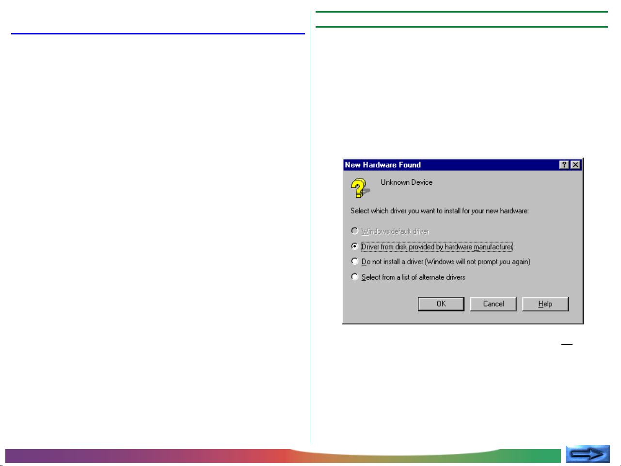
If you will be connecting your Nikon scanner for the first time,
you will need to register your scanner with Windows’ Device
Manager. Connect your Nikon scanner to your computer’s
SCSI chain as described in the scanner’s documentation. Turn
on your Nikon Scanner and then turn on your computer and
start Windows 95. The following message will appear on the
desktop.
After checking the above points, start installation as described
below.
Before You Begin: Software Installation
Select Driver from disk provided by hardware manufacturer and click OK.
Note: This dialog will not appear if you are using Windows NT.
Insert the installation CD into the CD-ROM drive and proceed
directly to Step 2.
- 7 -
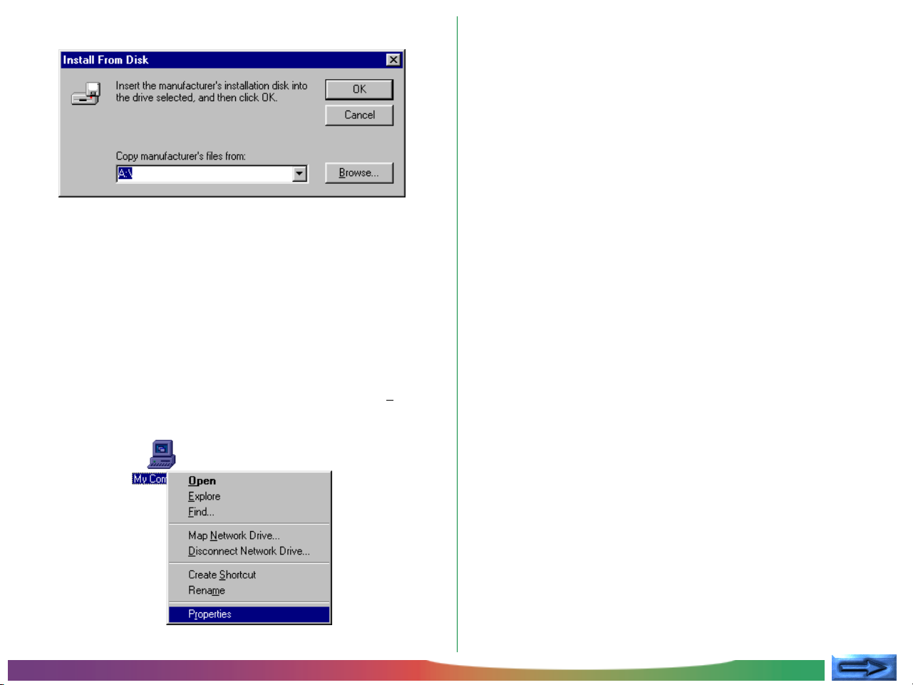
The Install From Disk dialog will appear.
After inserting the installation CD into the CD-ROM drive,
enter the drive letter for the CD-ROM drive in the Copy
manufacturer's files from: text box and click OK. A
progress indicator will be briefly displayed while Windows
adds the Nikon scanner to your system.
Once Windows has registered your scanner, you can check
that it has been added to your system by clicking the My Computer icon with the right mouse button and selecting Proper-
ties from the menu that appears.
This will open the System Properties window. Select the
Device Manager tab and confirm that the scanner is shown in
the list of devices under “Nikon Scanners.”
Before You Begin: Software Installation
- 8 -
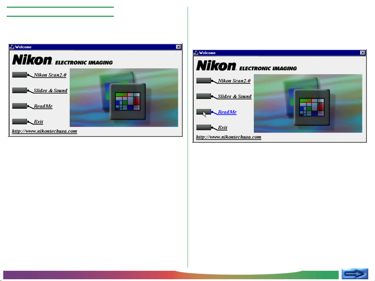
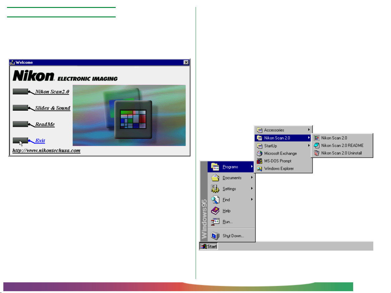
Step 2—View the “Read Me” file
When the Nikon Scan 2.0 CD-ROM is inserted in the drive, the
following Welcome dialog will appear on the desktop.
It is recommended that you take a few moments to view the
Read Me file, which contains important information about the
software provided with your scanner. Click ReadMe to open
the Read Me file.
Note: If the autorun feature is disabled on your computer, the
above dialog will not appear when the disk is inserted in the drive.
To start the installer, double-click the My Computer icon to access
your computer’s drives, then double-click the Nkscan20 CD icon.
In the Nikon Scan CD folder, double-click Welcome.exe to start
the installer program.
Before You Begin: Software Installation
Note: The Read Me file will be opened in the Notepad applica-
tion, where the contents of the file can be viewed or printed.
When you have finished, click the close box at the top right corner
of the Notepad window to return to the Nikon Scan Welcome
window.
- 9 -
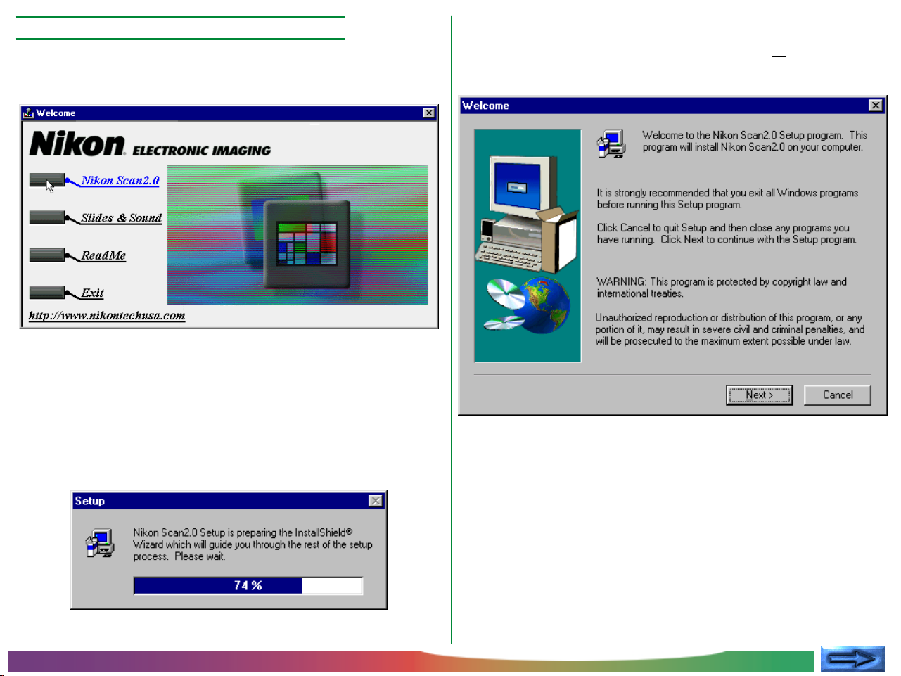
Step 3—Start the Nikon Scan 2.0 installer
To install Nikon Scan, click the Nikon Scan 2.0 button in the
Welcome dialog.
A dialog will appear prompting you to select a language for
Nikon Scan’s menus and dialogs. Select the desired language
from the list provided (please note that the dialogs and menus
shown in this manual are for the English version of Nikon Scan).
A progress indicator will be displayed while the Nikon Scan 2.0
installer loads.
Once this initialization process is complete, the following installer Welcome dialog will be displayed. Click Next to go to
the next step.
Before You Begin: Software Installation
- 10 -
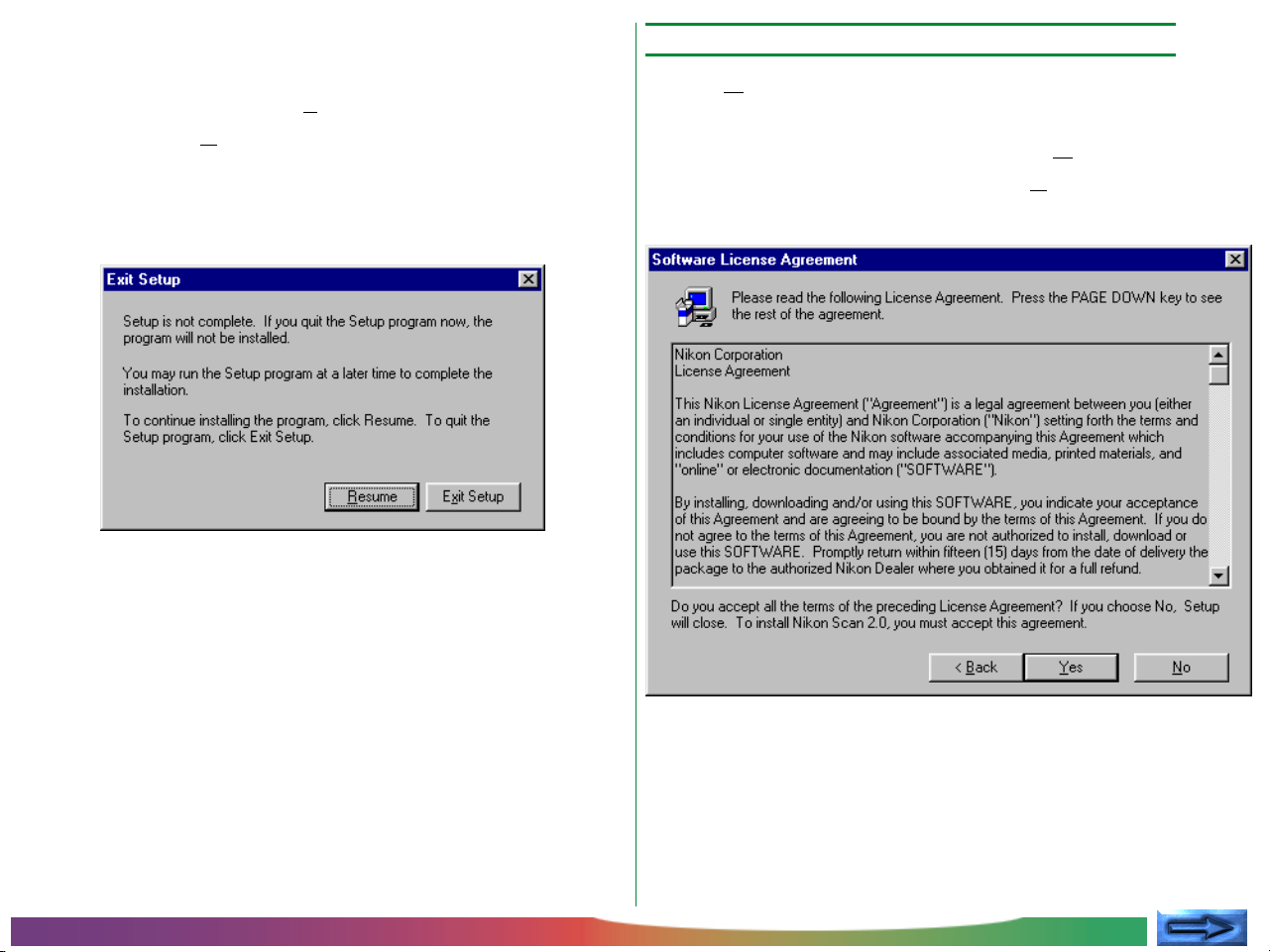
Cancelling installation
Selecting Cancel in the Welcome dialog displays the dialog
box shown below. Choose Exit Setup to quit without installing Nikon Scan, or Resume to continue installation. Should
you choose to exit the installation program, you will still be able
to complete installation at any time by repeating the process
from Step 2.
Step 4—Accept the software license agreement
Clicking Next in the Welcome dialog box brings up the Software License Agreement dialog. To install Nikon Scan, you
must accept this agreement. If you choose No, the Exit Setup
dialog shown at left will appear. Clicking Back will return you
to the previous step.
Before You Begin: Software Installation
- 11 -
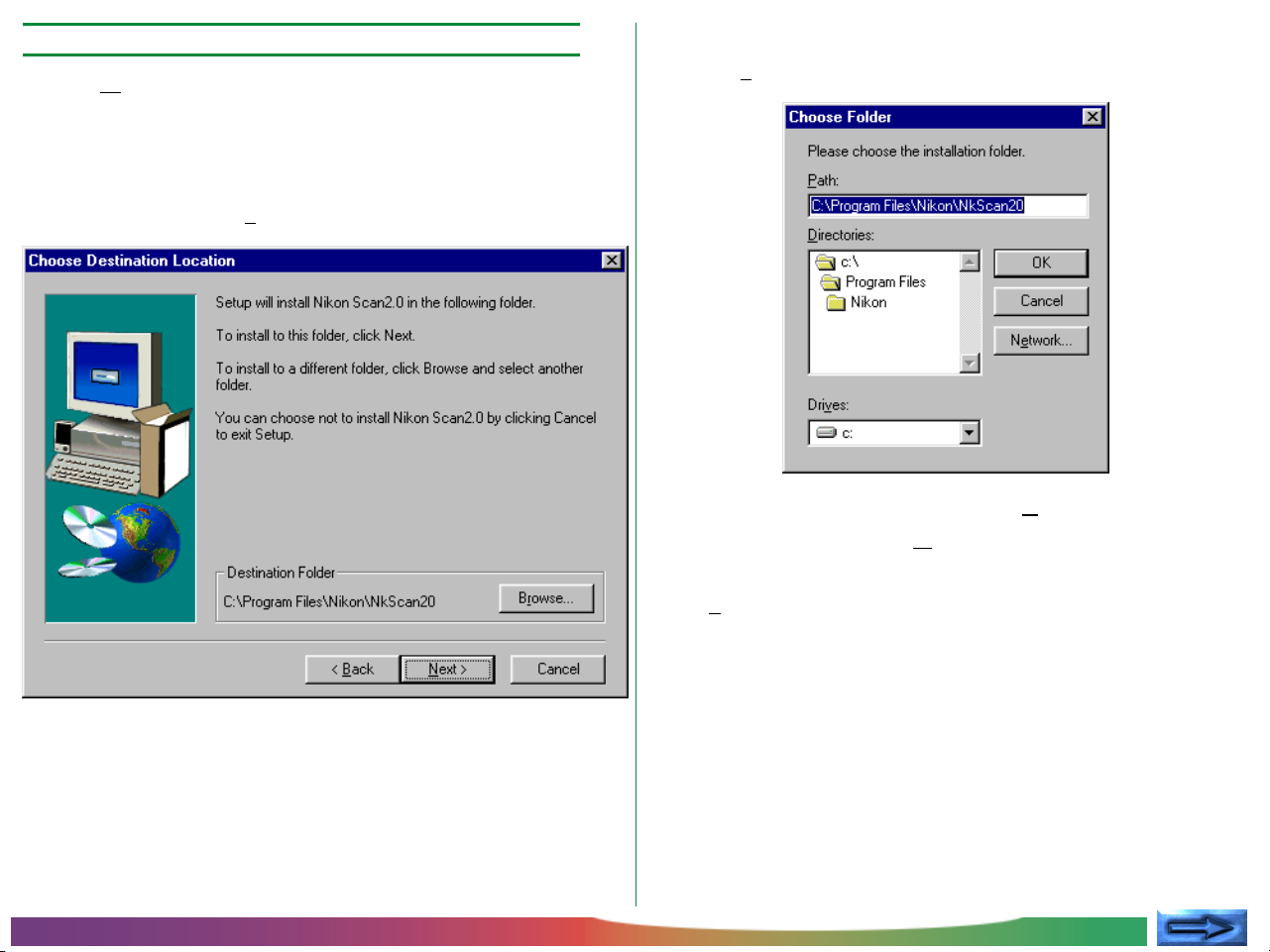
Step 5—Select a destination folder for Nikon Scan
Clicking Next in the Software License Agreement dialog box
brings up the Choose Destination Location dialog box. The
default folder (directory) for Nikon Scan 2.0 is displayed
under Destination Folder. If you would like to choose a
different folder, click Browse.
Choosing a folder for installation
Clicking Browse brings up the Choose Folder dialog box.
You can type a destination folder in the Path text box, or click
on the folders shown under Directories to navigate to an
existing folder on the current drive. Clicking on the arrow next
to Drives allows you to select a another drive from a pop-up
menu.
Note: This manual uses “folder” in place of the term “directory,”
familiar to many long-time Windows users.
Before You Begin: Software Installation
- 12 -
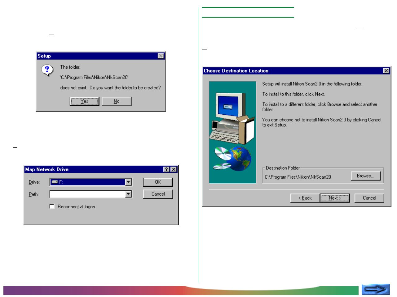
Click OK when you have chosen a destination folder. If the
specified folder does not already exist, the following dialog will
appear. Click Yes to create a new folder with the specified
name.
Map Network Drive
To install Nikon Scan to a network drive (if available), click the
Network button in the Choose Folder dialog box. The following dialog will appear.
Step 6—Install Nikon Scan
Once you have chosen a destination folder, click the Next
button to install Nikon Scan 2.0 in the selected folder. Click
Back to return to the previous step, or Cancel to bring up
the Exit Setup dialog box.
Select a drive and path from the pop-up menus and click OK.
If Reconnect at logon is checked, the drive will be recon-
nected whenever you log in.
Before You Begin: Software Installation
- 13 -
Clicking Next in the Choose Destination Location dialog box
causes Nikon Scan 2.0 to be installed in the specified folder.
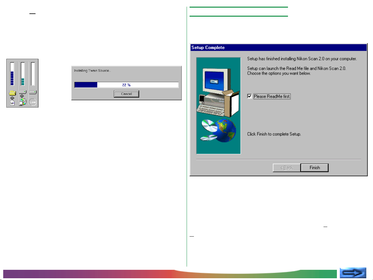
The following progress indicators will be displayed while Nikon
Scan's program files and drivers are being copied to your hard
disk.
Clicking Cancel interrupts the installation and brings up the
Exit Setup dialog box, allowing you to exit the setup program
without adding Nikon Scan 2.0 to your system.
Step 7—Complete installation
Once the installer has finished copying Nikon Scan 2.0 to the
destination directory, the following dialog will be displayed.
Before You Begin: Software Installation
Click Finish to exit the setup program. If “Please ReadMe first”
is checked, the Read Me file will be opened in the Notepad
accessory. It is recommended that you read the Read Me file,
which may contain information that could not be included in
the manuals. When you have finished, choose Exit from the
File menu to close the Read Me file. It can be viewed again at
any time by opening the copy of the Read Me file located in the
folder you chose as the destination for Nikon Scan 2.0.
- 14 -
Step 8—Exit the setup program
After the ReadMe file has been closed, the initial Welcome
dialog will reappear. Click Exit to exit the setup dialog and
return to Windows.
The other items in this dialog box are explained below.
Slides & Sound
Install Slides & Sound Plus.
URL
If you have an Internet connection, clicking the URL at the
bottom of the Welcome dialog will start your Web browser
(Netscape Navigator 3.0 or better or Internet Explorer 3.0
or better required) and take you to the Nikon technical
support home page for the region in which your scanner was
purchased.
There is no need to restart your computer after completing
installation. After clicking Exit to close the Welcome dialog,
you will find Nikon Scan registered in your computer’s Start
menu.
ReadMe
View the ReadMe file.
Before You Begin: Software Installation
Note: For information on uninstall and on the location of files
installed by the Nikon Scan 2.0 installer, see Appendices B and C.
- 15 -
Basic Operations
Step 2—Start Nikon Scan
This chapter provides a brief introduction to Nikon Scan’s
windows, menus, and buttons, and guides you step-by-step
through the basics of using Nikon Scan 2.0 to acquire images
from your scanner, modify them, and save them to disk. The
details of each operation will be provided from the following
chapter on.
Note: In addition to the strip-film and slide adapters provided
with your scanner, a slide feeder and IX240 film adapter are
available separately for the LS-2000.
Step 1—Connect the scanner
Connect the scanner to your computer as described in the
scanner manual or User’s Guide, first making sure that both
devices are off. Turn the scanner and any other peripheral
devices on, then turn on your computer and start Windows.
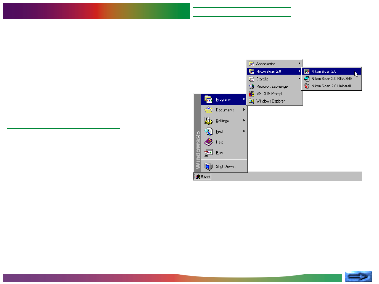
Once Nikon Scan 2.0 has been installed, a program icon will
appear in the Window’s Start menu as shown below. Nikon
Scan 2.0 can be started by selecting this icon from the Start
menu.
Basic Operations
- 16 -
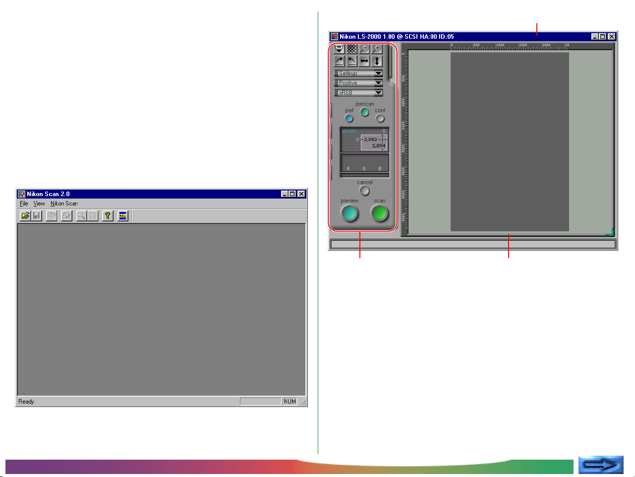
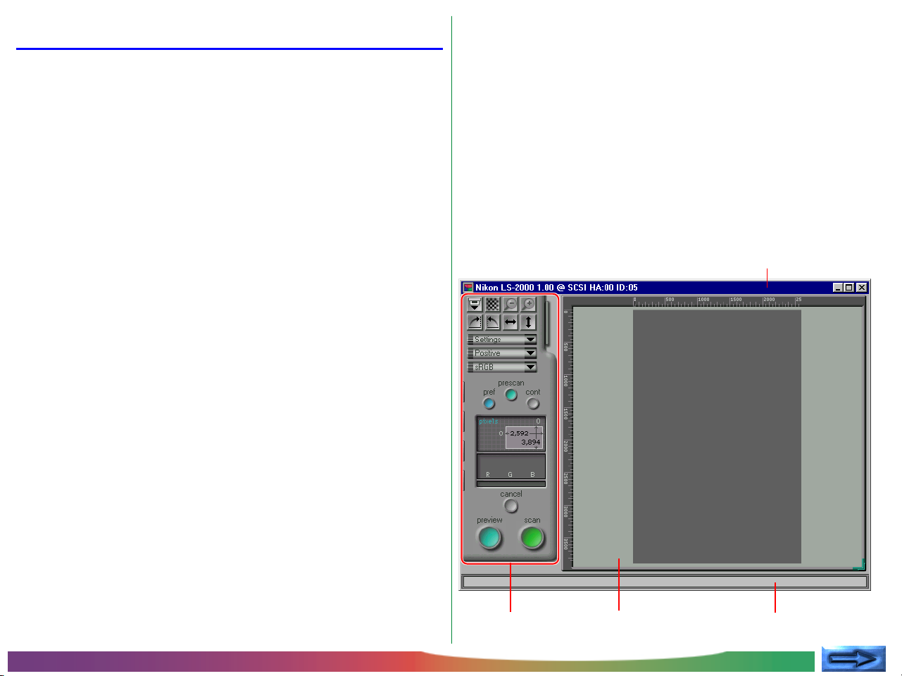
Once Nikon Scan 2.0 has been selected from the Start menu,
the main window will appear, followed by the scan window,
where you will preview images and make adjustments prior to
scanning. At the left side of the scan window is a control area
containing a collection of buttons and menus, while on the right
is the preview-image display area in which a preview of the
image to be scanned is displayed. If no adapter is in the scanner
or if no film is inserted in the adapter, all controls other than the
preferences button will be grayed out and inactive.
▼ The Nikon Scan main window
▼ The Nikon Scan scan window
Title bar
Basic Operations
Control area
Preview/crop area
Note: If the MA-20 Slide Mount Adapter is inserted in the LS-2000
film scanner, all controls will be active regardless of whether there is a
slide in the adapter or not. If there is no slide in the adapter, clicking
the autofocus, prescan, preview, or scan buttons will produce an error.
Click OK in the error message box, check that a slide is inserted in the
adapter, and repeat the autofocus, prescan, preview, or scan operation.
- 17 -

Launching Nikon Scan from another application
Choosing a scanner
The scan window can also be opened from any TWAINcompliant application by first selecting Nikon Scan 2.0 as the
application’s thirty-two–bit TWAIN source and then choosing
“acquire from 32-bit TWAIN source” from the application’s
acquire menu. See the application manual for details. When
Nikon Scan 2.0 is used as a TWAIN source for another application, the main window will not open; instead, images will be
passed directly to the calling application when scanned.
Nikon Scan will open a separate scan window for every supported scanner that is connected and powered on at the time
the application starts up. The name, firmware version number,
host adapter ID, and SCSI ID of each scanner is shown in the
scan window title bar. Click the scan window for the desired
scanner to activate it and bring it to the front, or close unneeded windows by clicking the close button at the right end of
the title bar (see “The Scan Window,” below).
Basic Operations
- 18 -
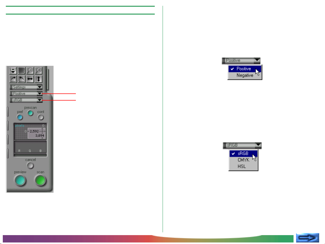
Step 3—Choosing a film type and color space
Having chosen a scanner, select the type of film to be scanned
and the “color space” to be used when scanning the image and
displaying it in the scan window. Film type and color space may
be selected from pop-up menus in the control area of the scan
window.
Film type selection
Clicking the film-type menu button will display the pop-up
menu shown below. Select the type of film currently in the
scanner. The chosen film-type will be displayed on the menu
button. (More details on film-type selection may be found in
“Preview,” below.)
Film-type menu button
Color-space menu button
Color space selection
Clicking the color-space menu will display the pop-up menu
shown below. Click a color space to select it from the list (the
default is “sRGB”). The chosen color space will be displayed
on the menu button. (More details on color space selection
may be found in “Preview,” below.)
Note: If the “Use Nikon Color Management System” check-box
in the Color Management tab of the Preferences dialog box is off,
the color-space menu will differ from that shown above. The
alternative menu is shown in “Preview,” below.
Basic Operations
- 19 -
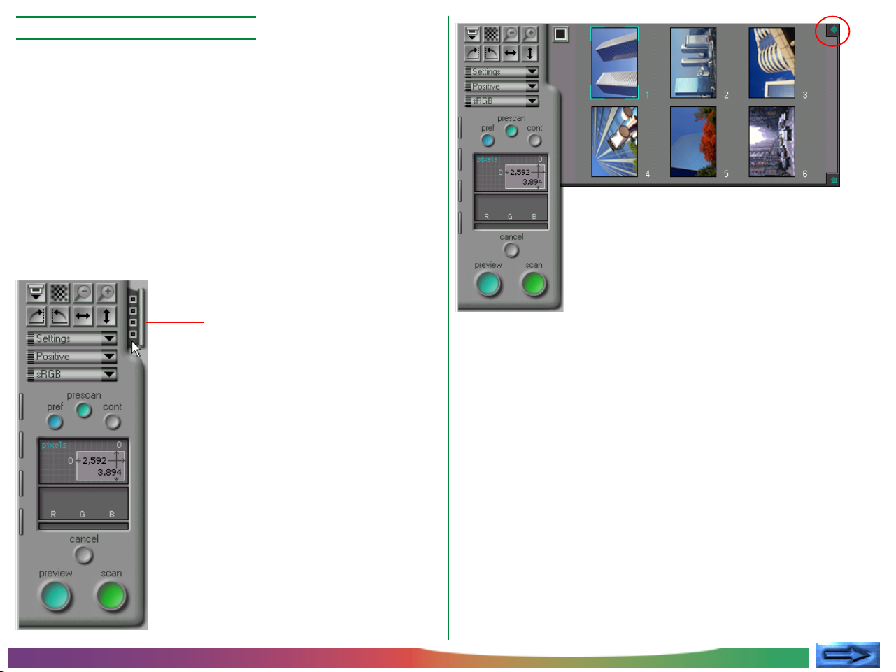
Step 4—Select thumbnails
When the strip-film or optional IX240 film adapter is in place,
clicking the thumbnail drawer-tab in the scan window control
area will open the thumbnail drawer. When the thumbnail
drawer-tab is clicked, Nikon Scan will create thumbnail preview
images for all frames in the scanner and display them in the
thumbnail drawer automatically.
The size of the thumbnail drawer can be changed by dragging
the lower right corner of the drawer. The drawer cannot be
made larger than the scan window.
Thumbnail drawer-tab
To select a particular frame for preview, click the associated
thumbnail. The selected thumbnail will be highlighted. If you
then click the preview button, the selected frame will appear
in the preview/crop area of the scan window, where it can be
cropped or scanned as described in the following sections. To
close the thumbnail drawer, click the button at the upper right
corner of the drawer. (More details on thumbnail display and
selection may be found in “The Thumbnail Drawer,” below.)
Basic Operations
Note: Nikon Scan’s thumbnail function can be used when scanning with the LS-2000’s strip-film adapter or the IX240 film
adapter available separately for the LS-2000. This function is not
available when scanning with other adapters or scanners.
- 20 -
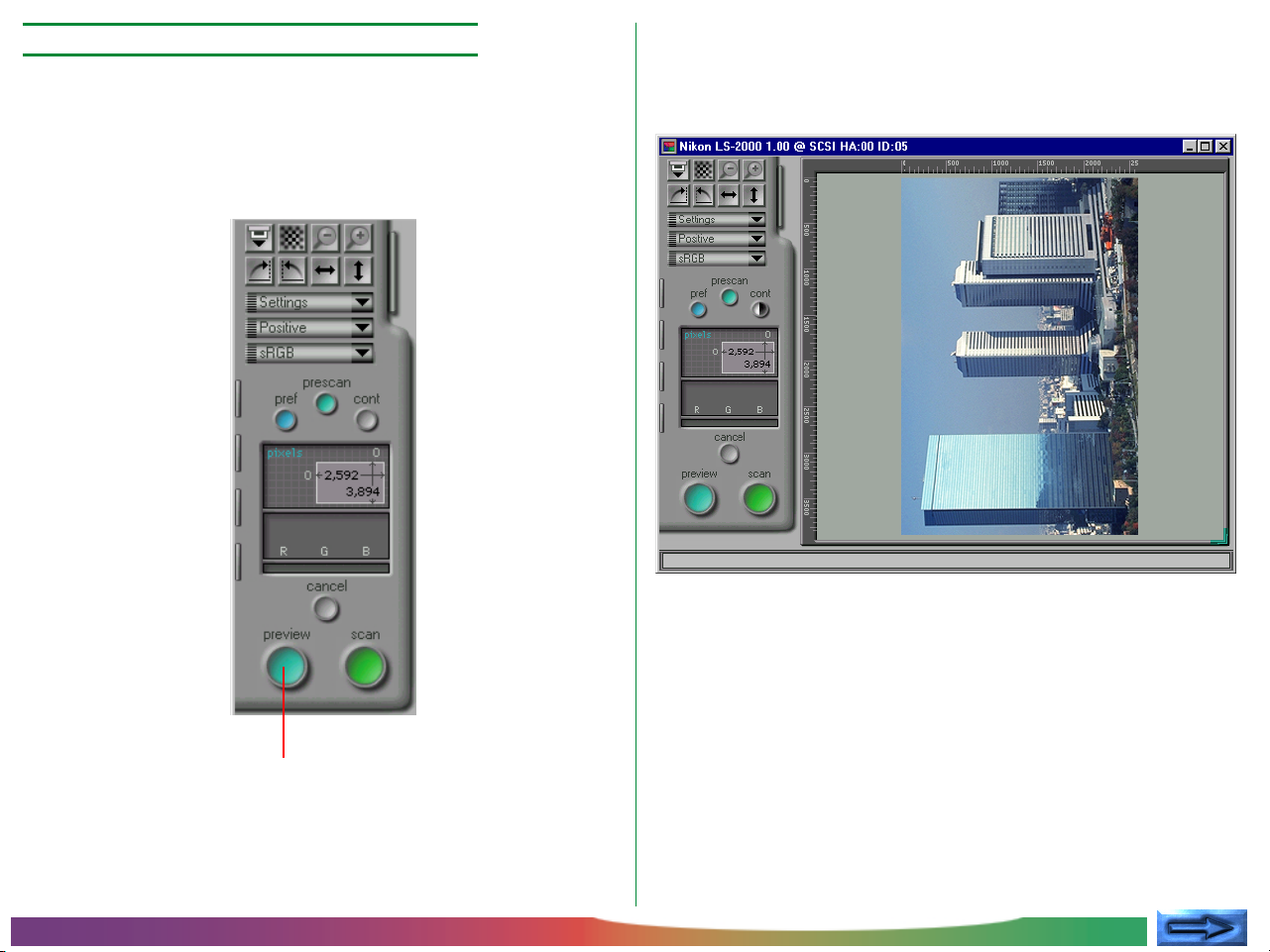
Step 5—Conducting a preview scan
Before actually scanning an image into your computer, conduct
a preview scan to select an area and orientation for the final
scan and to determine whether adjustments to scan settings are
necessary. To make a preview scan, click the preview button.
When the preview button is clicked, a preview scan will be
made using the current control and color-space settings, and
an image will be displayed in the preview-image display area.
Basic Operations
Preview button
- 21 -
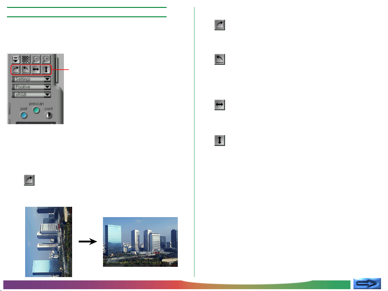
Step 6—Rotate and flip the preview image
Four buttons are used to control the orientation of the image:
Once a preview image is displayed in the scan window, it can
be rotated or flipped prior to scanning using the flip and rotate
buttons in the control area.
Rotate and flip buttons
For example, clicking the button below will rotate the preview
image ninety degrees clockwise. When the scan button is
clicked to make the final scan, the image will be read into Nikon
Scan’s Main window or other host application in this orientation.
Rotate 90º Clockwise
Click this button to rotate the preview
image clockwise, ninety degrees at a time.
Rotate 90º Counter-clockwise
Clicking this button rotates the preview
image counter-clockwise, ninety degrees at
a time.
Flip Horizontal
Clicking this button flips the preview image
horizontally.
Flip Vertical
Clicking this button flips the preview image
vertically.
Basic Operations
- 22 -
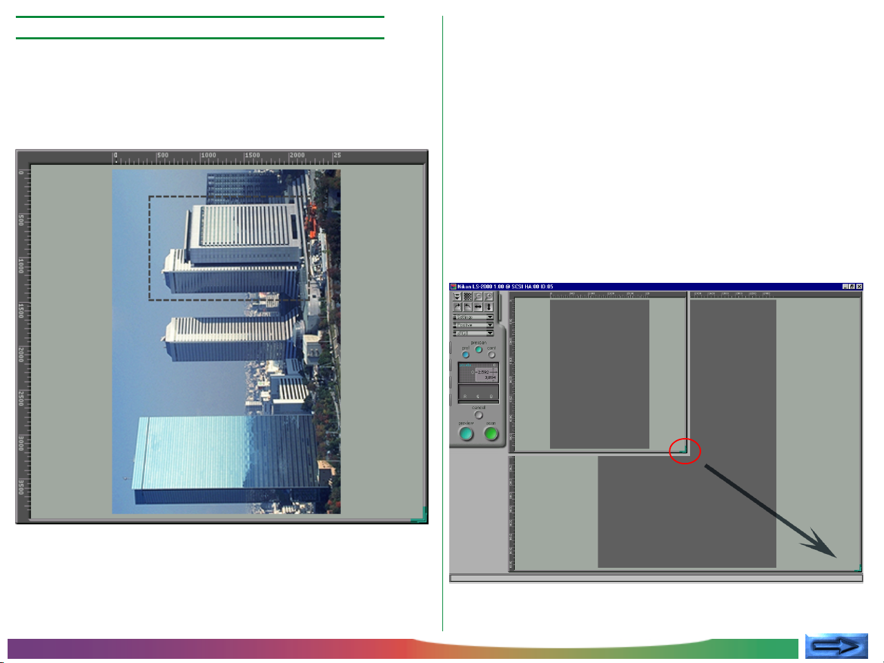
Step 7—Choose an area for the final scan
If so desired, an area and location for the final scan can be
selected by dragging the mouse to specify a rectangular crop
area in the preview-image display. Only the area within the
crop will be included in the final scan.
Note: Information on the current crop appears in the control
area, where the height and width and the coordinates of the top
left corner of the crop are displayed. For details on how to specify
file size and output resolution for the final scan, see “Preview”
and “The Scan Size Drawer,” below.
The size of the preview-image display can be changed by dragging its lower right corner or the entire preview/crop area can
be repositioned by dragging the rulers on the top and left
borders of the display. The preview area can not be made
larger than the scan window as a whole, but the scan window
can be enlarged by dragging its borders if necessary.
Basic Operations
- 23 -
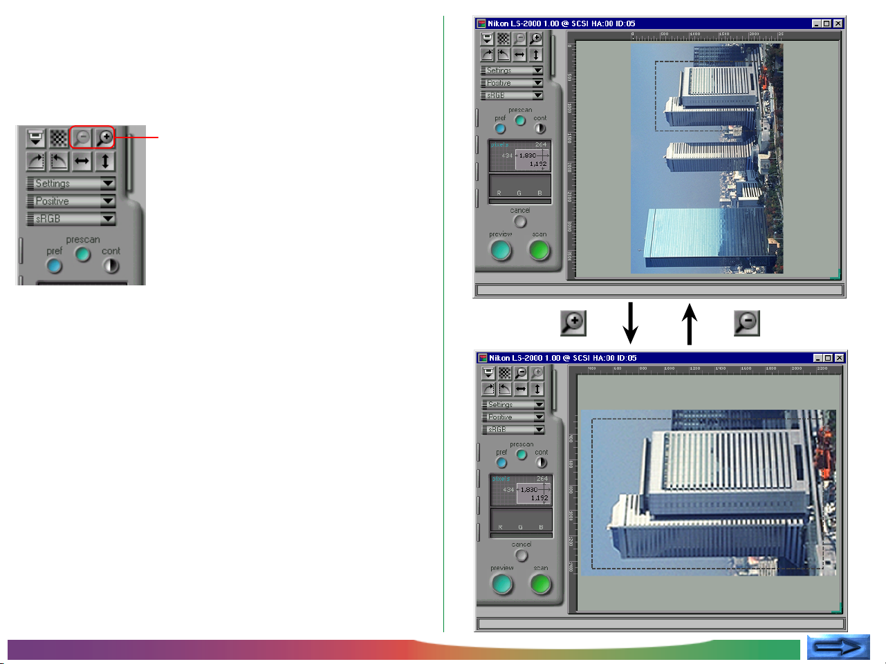
Zooming the crop area in and out
Clicking the zoom-in button will expand the currently selected
crop to fill the preview area. The original view can be restored
by clicking the zoom-out button.
Zoom buttons
Basic Operations
Zoom-in
button
Zoom-out
button
- 24 -
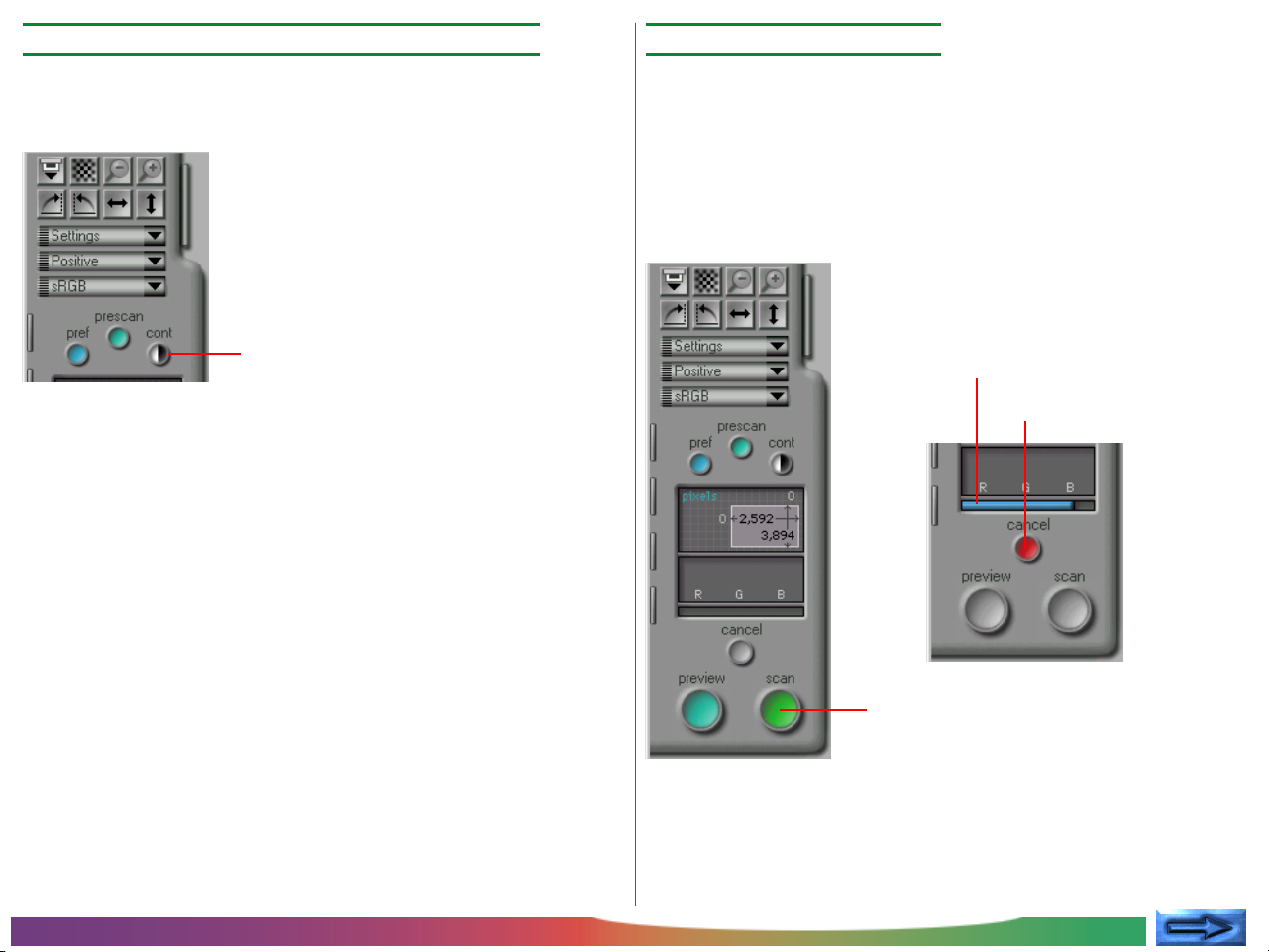
Step 8—Automatic contrast adjustment
Step 9—Scan an image
If desired, Nikon Scan is capable of modifying contrast adjustment automatically. Simply click the contrast button.
Contrast button
Note: When the contrast button is clicked, Nikon Scan analyzes
the preview image to maximize contrast. The tone curve that will
produce the best possible results is automatically selected. For
manual tone-curve adjustment, refer to “The Curves and Levels
Drawer.” The original contrast can be restored by clicking the
reset button in the curves-and-levels drawer.
If, after specifying a crop and adjusting contrast, you are satisfied
with the preview image, click the scan button to perform the
final scan.
While scanning is in progress, the following indicator will be
displayed. Clicking the cancel button stops scanning.
Progress indicator
Cancel button
Basic Operations
Scan button
- 25 -
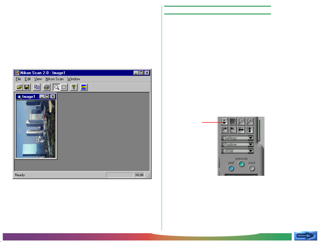
The scanned image will not appear in the scan window; instead,
the image will be passed to the host application. If you are
using Nikon Scan as a stand-alone application, the image will be
opened in an image window in the main window where it can
be saved to disk, printed, or flipped and rotated using the
commands available in the main window.
▼ Scanned image opened in an image window in Nikon Scan
Step 10—Scan additional images
If the scan window is clicked, the
vated and another image can be scanned
Nikon Scan 2.0 from within another application, select Nikon
Scan from the application’s acquire menu). When additional
images are scanned, each will appear in an image window in
the host application or Nikon Scan’s main window.
Note: If a slide feeder is being used with the LS-2000 film
scanner, clicking the Eject and Feed button in the scan window will
eject the current slide and feed the next one. This button can also
be used to eject film from the LS-2000’s strip-film or IX240
adapters.
Eject and feed
button
scan window will be acti-
(if you are using
Note: When open, the scan window will always appear in front
of the main window whether the scan window is active or not. If
your monitor is big enough, you can move the windows so that
both are visible. If there is not enough room on the desktop for
both windows, close the scan window after completing a scan.
Basic Operations
- 26 -
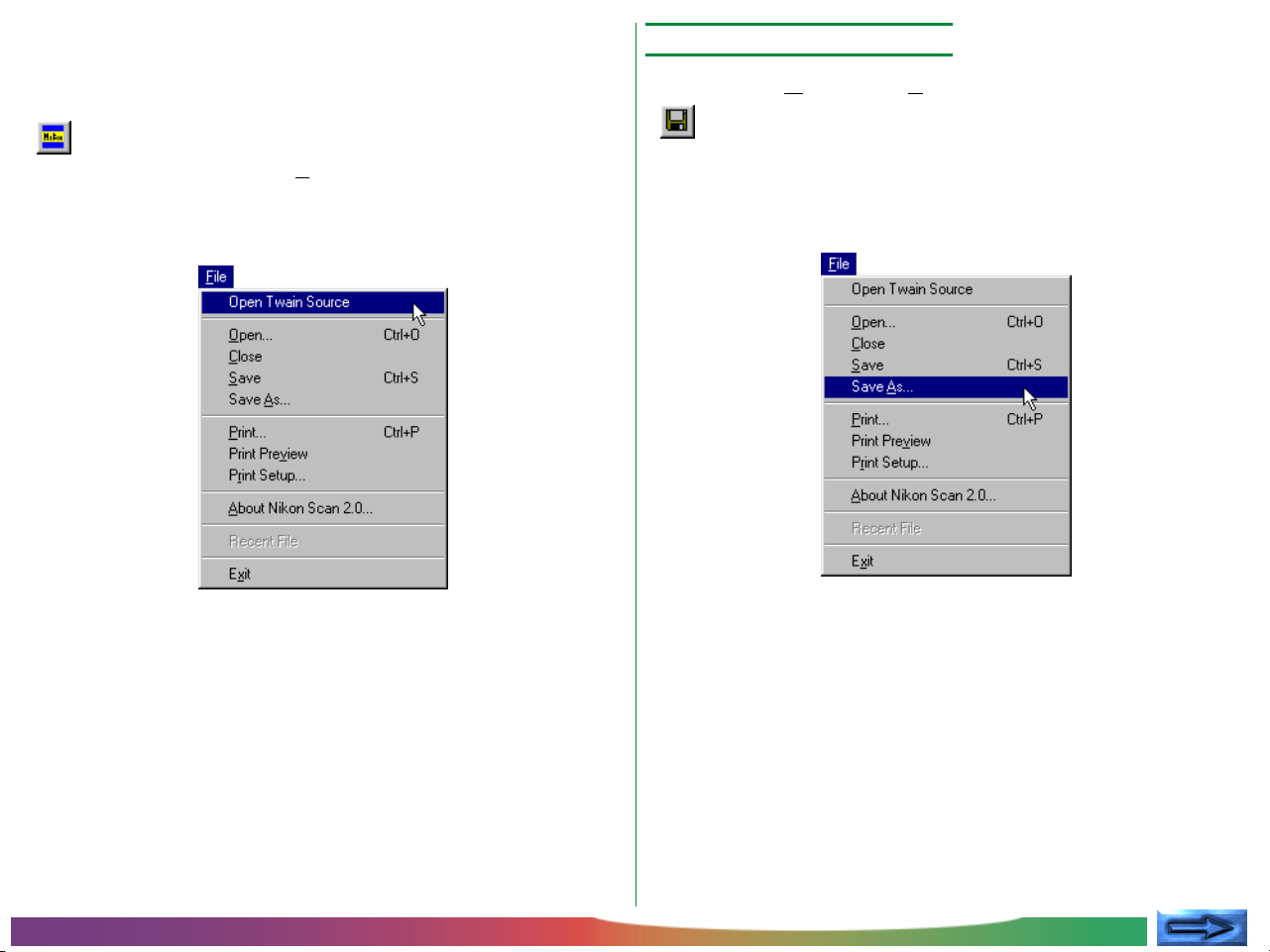
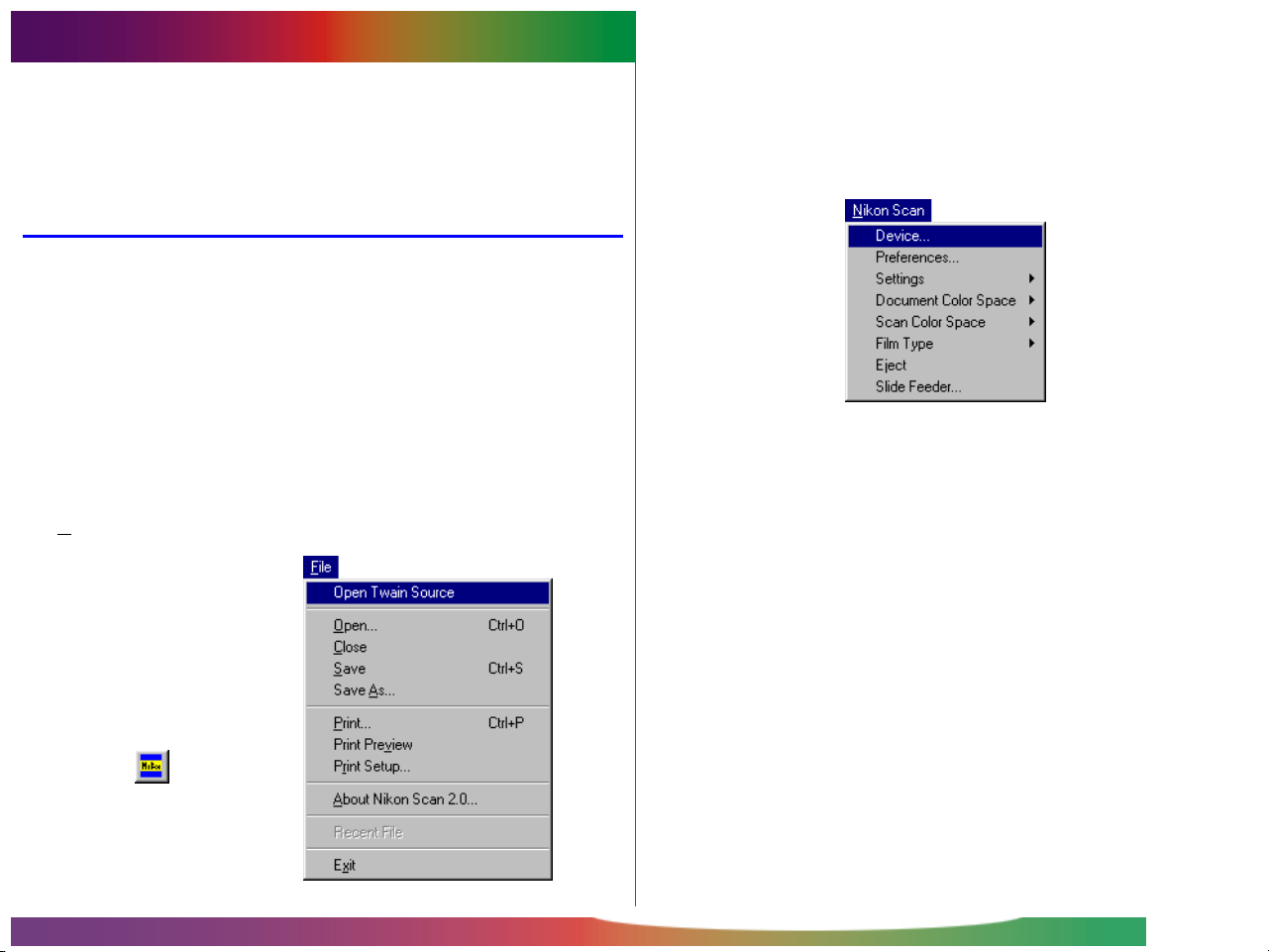
Opening the scan window
If the scan window is no longer open on the desk top, a scan
window can be opened by clicking the Open Source button
( ) in the main window or choosing the Open Twain
Source command from the File menu. To re-launch Nikon
Scan from another application, select Nikon Scan from the
application’s acquire menu.
Step 11—Saving images
Choose Save As from the File menu or click the Save button
( ) in the main window to save the image in the active
image window (if more than one image window is open in the
main window, click the image to be saved once to activate the
window).
Basic Operations
- 27 -
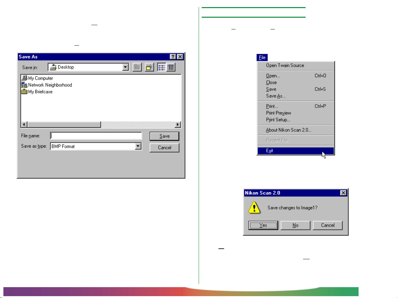
If the image has not been saved before, or is being saved under
a new name using the Save As command, the following Save
As dialog will appear. Specify a file-name, folder (directory), and
file-type, then click the Save button.
(More details on file-type selection may be found in “Image
Window Operations,” below.)
Step 12—Exit Nikon Scan
Choose Exit from the File menu or click the close box at the
top right corner of the Main window to close all Nikon Scan’s
windows and exit from Nikon Scan.
If a scanned image has yet to be saved, the following dialog will
appear.
Basic Operations
Click Yes to display the Save As dialog shown above, where
the image can be saved. Clicking No closes Nikon Scan
without saving the image. Click Cancel to return to the
main window.
- 28 -
The Scan Window
The “scan window” is where scans are performed and scan
settings adjusted. This chapter overviews basic scan window
layout and settings.
Opening the Scan Window
When Nikon Scan is started, one scan window will be opened
for each supported scanner connected and powered on (you
can choose the scan window to be opened at start up using
the Preferences dialog box as described in “The Scan Window:
Preferences,” below). The scan windows for the scanners
currently selected in the Preferences dialog can be re-opened
from the main window by clicking the “Open Twain Source”
button on the tool bar or selecting Open Twain Source from
the File menu.
The scan window for a particular scanner can be opened by
choosing Device from the NikonScan menu in Nikon Scan’s
main window. The Device tab of the Preferences dialog will
appear. Choose the scanner from the list of those available and
select open now (see “The Scan Window: Preferences,” below).
If Nikon Scan is functioning as a TWAIN source to scan images
into other applications, the scan window can be opened when
Nikon Scan is the selected source and the “acquire from 32-bit
TWAIN source” command is chosen from the application’s
acquire menu.
Open Twain Source
button
The Scan Window: Opening the Scan Window
- 29 -
The Parts of the Scan Window
The scan window is composed of the following sections:
• the title bar
• the control area
• the preview/crop area
• the interactive help display
The control area is the area on the left side of the scan window
containing a crop information display and the buttons and tabs
used in changing scan settings. The image to be scanned is
previewed in the preview/crop area on the right of the window,
where the area to be scanned (called a “crop”) can be selected.
The title bar, at the top of the window, shows the name and
firmware version of the scanner currently selected and gives its
SCSI ID and the ID of the host adapter. The interactive help
display, at the bottom of the window, displays help messages
when the cursor is moved over controls in the scan window.
Title bar
The Scan Window: The Parts of the Scan Window
Control area
Preview/crop area
Interactive help
display
- 30 -

Active controls
The buttons in the control area are active at different times
during the preview and scanning process depending on the
media and adapter used. Controls that are inactive are not
colored or are “grayed out.” If the current adapter allows
sequential scanning of multiple images, a thumbnail drawer
non-
-tab
will be displayed at the top of the control area. This tab will not
be displayed when a slide adapter is inserted in the scanner.
Moving the cursor over any of the drawer-tabs at the left side
of the control area causes the tab to pop out. Click the tab to
open the drawer and view the controls it contains. The drawer
can be closed by clicking the arrow tab at the right side of the
drawer.
Control area for
multiple-image adapters
Control area for
slide adapters
Thumbnail
drawer-tab
Drawer tab
Drawer
The Scan Window: The Parts of the Scan Window
- 31 -

The drawer tabs at the left of the control area can be moved
up or down by dragging any one of the tabs, enabling the user
to see any controls that might be hidden when a drawer is
open. When a drawer is open, the drawer can be moved up or
down by dragging its frame.
No film/no adapter
If no adapter is inserted in the scanner or if no film is in the
adapter, the scan window will be grayed out and all controls
other than the preferences button will be inactive. The controls and settings in the scan window will remain active if the
slide mount adapter or the slide feeder is removed from the
scanner, but the controls will not function as expected. For
example, clicking the scan button will produce an error.
The Scan Window: The Parts of the Scan Window
Note: Adapters will not be recognized unless fully inserted in the
scanner.
- 32 -

Moving and Resizing the Scan Window
The scan window can be moved and resized using standard
Windows controls. Drag the edges of the window to adjust to
any size between 600 × 420 pixels and the dimensions of the
computer monitor. Drag the title bar to move the window
anywhere on the desktop.
The Scan Window: Moving and Resizing the Scan Window
- 33 -

The control menu
Clicking the icon at the left end of the title bar opens the standard Windows control menu for the scan window, which allows
you to
move, reduce to an icon, and change the size of the
window.
The control menu offers the following functions;
Restore: Restores the window to its original size
when it has been enlarged with the Maxi-
mize command.
Move: Lets you move the window using the arrow
buttons on the keyboard. Press the return
key when you have moved the window to
the desired position.
Close: Closes the window and returns you to the
calling application.
Some of these functions can also be performed using the
control buttons on the title bar.
Nikon Scan icon
Mi
nimize/Restore
ximize/Restore
Ma
Close
Size: Lets you re-size the window using the
arrow buttons on the keyboard..
Minimize: Minimizes the scan window.
Maximize: Enlarges the window to fill the screen.
The Scan Window: Moving and Resizing the Scan Window
- 34 -

Changing the size of the preview/crop area
The size of the scan-window control area is fixed, but the size
of the preview/crop area can be changed by dragging its
bottom right corner. The preview/crop area can not be
made larger than the scan window. The preview/crop area
can be moved anywhere in the scan window by dragging the
rulers at the top and left side of the area.
Moving the preview/crop area
Resizing the preview/crop area
The Scan Window: Moving and Resizing the Scan Window
- 35 -

Scan Window Preferences
This section discusses the scan window preferences, or basic
scan settings. Some of these settings depend on the scanner
selected.
Opening the preferences dialog
Clicking the preferences button in the control area of the scan
window, or selecting Preferences from the Nikon Scan
menu in the main window, displays the Preferences dialog box
shown opposite.
Preferences button
The Preferences dialog contains the following four tabs:
• gamma tab
• color management tab
• device tab
• miscellaneous tab
The tab currently displayed is indicated by a dark green bar
above the name of the tab. Clicking the OK button at the
bottom of the window saves any changes to preferences and
returns you to the previous window. Clicking cancel returns
you to the previous window without saving changes.
The Scan Window: Preferences
- 36 -

The Device tab
The Device tab is shown below.
not available:
a previously-connected scanner is either no
longer connected or is off
Selecting the scan window(s) to be open at startup
Using the Device tab in the Preferences dialog, it is possible
to select what scan windows will be opened at start-up when
multiple supported scanners are connected and powered on.
The scan window for devices marked with a bullet in the
select scanner(s) list-box will be opened automatically
when Nikon Scan starts up. To have the scan window for a
given device open at start-up, select the device in the select
scanner(s) list-box and click the open at startup button.
Clicking the button a second time to prevent the scan window for the device from opening automatically. To remove
an unavailable device from the list of scanners, select the
device and click the remove item button. Devices that
were open in your last session of Nikon Scan cannot however
be removed.
Device status
The Device tab gives the status of the devices available, together with their name and SCSI ID.
open:
closed: the device is connected but the scan window
The Scan Window: Preferences
the scan window for this device is currently open
for the device is closed
Opening a scan window from the Preferences dialog
The scan window for devices currently marked as closed can be
opened by selecting the device in the select scanner(s) listbox and clicking open now. This operation has no effect on
whether the scan window for the device will open at start-up.
- 37 -

The Gamma tab
The Gamma tab in the Preferences dialog allows the user to set
the output gamma values used in displaying preview images and
in making the final scan.
Preview gamma
Gamma compensation for the scan window can be set by direct
input or using the slider. Adjust the gamma value so that the
gray patterns above the gamma slider match in density. When
performing this adjustment, it is best if you set the resolution of
the monitor to a low value such as 640 × 480 dots and sit as far
away from the monitor as possible. To restore the factory
default gamma value of 2.2, click the reset button.
Main scan gamma
Main scan gamma is used when the image in the scan window
is scanned and passed to the host application (if you are using
Nikon Scan as a “stand-alone” application, preview gamma
will be used when the image is scanned; hence the main scan
area will not appear in the Gamma tab). The gamma value
used in the final scan can be chosen from the following options:
use preview gamma
The gamma value for the final scan will be the same as that
shown in the preview gamma text box.
Note: If you are using the Nikon Color Management System, you
can specify that the gamma values set in the Gamma tab not be
used. See “The Color Management tab,” below.
The Scan Window: Preferences
use application gamma
The gamma value of the calling application is used.
use custom gamma
A value for main scan gamma can be entered in the text box.
- 38 -

The Color Management tab
Nikon Scan’s Color Management System (CMS) allows you to
select calibrated RGB (sRGB), CMYK, and HSL color models as
the color space for displaying and modifying images prior to
scanning. You can adjust Nikon Color Management settings
using the Color Management tab in the Preferences dialog.
If the “use Nikon Color Management System” check-box
in the top of Color Management tab is on (the default setting),
the Nikon Color Management System will be used. When
CMS is on, the user can choose from sRGB (calibrated RGB ),
CMYK, and HSL color spaces. When off, only RGB and grayscale color spaces are available. To put changes to Color
Management settings into effect, click the OK button to close
the Preferences dialog, then exit and restart Nikon Scan.
Output color space
The color space used when the image is scanned and passed
to the host application depends on whether Nikon Color
Management is used. When CMS is used and Nikon Scan is
being used as a TWAIN source, the color space chosen in the
scan window color-space pop-up menu (sRGB, CMYK, or HSL)
is used in the scan window only; when scanned, the image is
passed to the host application as RGB data. When Nikon Scan
is being used as a “stand-alone” application, the color space
does not change when the image is scanned. If CMS is not
used, the scanned images will be passed to the host application
using the color space specified in the scan window (RGB or
grayscale).
The Scan Window: Preferences
- 39 -

Color management settings
The settings in the Color Management tab apply only when
Nikon Color Management is on. The following three types of
settings are available:
• preview settings (monitor profile)
• main scan settings (output profile)
• CMYK settings
When Nikon Scan is being used as a “stand-alone” application,
the output profile is the same as the monitor profile, and the
main-scan settings sheet is not available.
Note: Incorrect color management settings could result in loss of
image quality. It is recommended that you use the factory default
settings for most purposes.
The Scan Window: Preferences
- 40 -

Preview settings (monitor profile)
The Preview sheet in the Color Management tab allows you to
choose a monitor profile.
The following choices are available:
use factory default monitor profile
Nikon Scan’s monitor profile is used (default setting).
use custom monitor profile
This option allows the user to choose a monitor profile
supplied by the monitor’s manufacturer. When this radio
button is on, the choose profile button will be active.
Clicking the choose profile button displays a standard
open dialog, allowing you to navigate to the folder containing the manufacturer’s profile. The selected path will be
displayed in the text box below the radio button.
use preview gamma (overrides profile gamma)
If this check-box is on, the preview gamma value specified in
the Gamma tab (see above) will be used in place of the
default or custom monitor profile.
The Scan Window: Preferences
- 41 -

Main scan settings (output profile)
The Main Scan sheet in the Color Management tab allows you
to select the profile used when scanned images are transferred
(output) to the host application (these settings are not available
when Nikon Scan is used as a “stand-alone” application).
The following settings are available:
use preview profile
The monitor profile settings specified in the Preview sheet
are used. This is the default setting.
fixed sRGB profile
A fixed sRGB (calibrated RGB) profile is used.
use main scan gamma (overrides profile gamma)
When this check-box is on, the gamma value specified for
main scan gamma in the Gamma tab (see above) will be
used.
The Scan Window: Preferences
- 42 -

CMYK settings
The CMYK color model is used for output on standard fourcolor printers. A custom CMYK profile can be chosen in the
CMYK sheet of the Color Management tab.
The following settings are available:
use default CMYK
Nikon Scan’s default color library is used (default setting).
use custom profile
This option allows the user to choose the color library to be
used. When this radio button is on, the choose profile
button will be active. Clicking the choose profile button
displays a standard open dialog, allowing you to navigate to
the folder containing the color library. The selected path will
be displayed in the text box below the radio button.
The Scan Window: Preferences
- 43 -

The Miscellaneous tab
The Miscellaneous tab in the Preferences dialog box determines the initial values for a number of scan window settings.
Autoexposure
By default, a prescan is performed to determine exposure levels
before a preview scan is made. If the perform autoexposure
before preview scan check-box is off, an autoexposure
operation will not be performed before the preview scan.
The perform autoexposure before main scan check-box
controls whether a second autoexposure operation will be
performed before the main scan. By default, no autoexposure
is performed before the main scan. If this check-box is on, an
autoexposure operation will be performed before the final scan.
Regardless of how these options are set, an autoexposure
operation will be performed when the prescan button in the
scan window is clicked.
Autofocus
By default, an autofocus operation will only be performed if
the autofocus button in the scan window is clicked (see
“Preview,” below). If the perform autofocus before main
scan check-box is on, an autofocus operation will be performed before the final scan. This option is not available when
the selected device does not support autofocus.
The Scan Window: Preferences
- 44 -

Batch scan
Some scanners, such as the LS-2000, can automatically scan
several frames of strip film or IX240 film in succession. Depending on the scanner, multiple images can also be scanned
automatically using a slide-feeder. If such a device is selected,
the scanner can be set to stop scanning after an error has
occurred by turning batch scan stops on error check-box
off (by default, the scanner will not stop scanning even when
an error has occurred).
Close thumbnails after preview
By default, the thumbnail drawer remains open after a preview scan is performed. If the close thumbnails after
preview check-box is on, the thumbnail drawer will close
automatically after a preview has been performed.
Acquire thumbnails
By default, the scanner creates and displays thumbnail previews
for all frames when the thumbnail drawer is opened.
always acquire thumbnails check-box is off, thumbnails will
not be created; instead, frames will be indicated by number
only. Thumbnails can be created and displayed by clicking the
“hide/display thumbnails” button in the thumbnails drawer.
Cache preview images
When a preview image is zoomed in, Nikon Scan stores the
previous preview image so that it can be quickly re-displayed
when the image is zoomed out. Setting the cache preview
images for slide mount adapter check-box to off forces
Nikon Scan to perform a preview scan every time the image is
zoomed out.
If the
Close window after scanning
By default, the scan window will remain open after an image
has been scanned and transferred to the host application or
to an image window in Nikon Scan. If the close window
after main scan check-box is on, the scan window will close
automatically when the scan button is clicked to scan an image.
Note: Some host applications may close the scan window after
scanning regardless of how this check-box is set.
The Scan Window: Preferences
Note: This function is only available when a slide adapter is
used.
Live picture updates
By default, changes to gamma curves are only reflected in the
preview image after a point on the curve has been dragged to
a new position and the mouse button released (see “The
Curves and Levels Drawer”, below). If the enable live picture
updates check-box is on, the preview image will be updated
continuously while points on the gamma curve are being
dragged
computer.
to a new position. This feature requires a powerful
- 45 -

The Thumbnail Drawer
When a scanner that supports non-sequential scanning of multiimage media such as strip film or IX240 film is selected, the scan
window’s thumbnail drawer-tab will be activated. Using the
thumbnail drawer, all images in the film can be previewed as
thumbnail images and one or more selected for full-scale preview or scanning.
Opening the Thumbnail Drawer
Click the thumbnail drawer-tab in the control area of the scan
window to open the thumbnail drawer.
Thumbnail drawer-tab
The thumbnail drawer can be closed by clicking the box at its
upper right corner.
Note: Nikon Scan’s thumbnail function is only available when the
scanner currently selected allows non-sequential access to multiple
images. Non-sequential access is supported on the LS-2000 when
SA-20 strip film adapter or the IA-20 IX240 film adapter are
inserted. When the strip film adapter is connected, two to six
thumbnails will be displayed depending on the number of frames in
the strip. Depending on the film used, fifteen, twenty-five, or forty
thumbnails will be shown when the IX240 adapter is in place. If
the current scanner or adapter does not support non-sequential
access, no thumbnail drawer-tab will be displayed.
The Thumbnail Drawer: Opening the Thumbnail Drawer
- 46 -

Displaying Thumbnails
Frame-number display
The contents of the thumbnail drawer can be displayed either
as thumbnail previews or as frame numbers only.
Thumbnail display
In this mode, small preview images, or “thumbnails,” of all
frames will be displayed in the thumbnail drawer. By default,
thumbnail previews will automatically be created and displayed
when the thumbnail drawer is opened.
Hide thumbnails button
Clicking the “Hide thumbnails” button in the thumbnail drawer
when thumbnails are displayed will replace the thumbnails with
a frame-number display.
In this mode, frame numbers are displayed in place of thumbnail
previews. The thumbnails will however be stored in memory,
making it possible to return instantly to a thumbnail display by
clicking the “Display thumbnails” button a second time. The
thumbnail images will be kept until the scan window is closed or
film ejected.
Display thumbnails button
Note: If in the Miscellaneous tab of the Preferences dialog the
“always acquire thumbnails” check-box is on (the default setting),
thumbnails will be created the first time the thumbnail drawer is
opened. As a result, it may take some time for the drawer to open
the first time the drawer-tab is clicked. If you prefer, you can
select the frame-number display. In this case, thumbnail images
are only created when the “Display thumbnails” button is clicked.
Note however that the LS-2000’s SA-20 strip-film adapter adjusts
frame settings when creating thumbnails. If you conduct a preview
scan without first creating thumbnails, the borders of the frames
may be slightly out of position when the image is previewed or
scanned.
The Thumbnail Drawer: Displaying Thumbnails
- 47 -

Resizing the Thumbnail Drawer
When there are too many frames to be displayed at one time
in the thumbnail drawer, a scroll bar will appear at the drawer’s
right border. Thumbnails can be scrolled a line at a time.
The drawer can also be enlarged or reduced in size by dragging
the re-size box at its lower right corner. The drawer cannot be
made larger than the scan window. The next time the thumbnail drawer is opened, it will be restored to the most recently
specified size.
The Thumbnail Drawer: Resizing the Thumbnail Drawer
- 48 -

Selecting Thumbnails for Scanning
Flipping and Rotating Thumbnail Images
Using the thumbnail drawer, frames can be selected for preview
and scanning. When a thumbnail or frame number is clicked, it
will be highlighted with a blue border to indicate that it has
been selected. Selected images can be previewed in the scan
window by clicking the preview button. A preview operation
will also be performed when a thumbnail or frame number is
double-clicked. After making any adjustments, click the scan
button to scan the image into the calling application or Nikon
Scan’s main window.
Selected frames in the thumbnail drawer can be rotated or
flipped prior to preview using the rotate and flip buttons in the
scan window’s control area.
Rotate and flip buttons
For example, clicking the “Rotate Clockwise” button ( ) with
a frame selected will rotate the thumbnail ninety degrees to the
right. When the frame is previewed, it will appear in the scan
window rotated ninety degrees clockwise.
The Thumbnail Drawer: Selecting Thumbnails for Scanning
- 49 -

Scanning multiple frames simultaneously
Selecting multiple thumbnails
Multiple frames can be selected for scanning by holding down
the ctrl key while clicking each frame in turn. Frames already
selected can be deselected by clicking them a second time.
When a frame is selected, clicking another frame with the shift
key held down will select all frames between the two. Flip and
rotate operations apply simultaneously to all selected thumbnails.
Scanning multiple thumbnails
Preview or scan operations can be performed on multiple
selected frames. When the preview button is clicked, a preview scan will be performed one at a time on the selected
frames and the resulting preview images stored temporarily in
memory. When any of the previewed thumbnails is subsequently selected in the thumbnail drawer, the preview for that
image will be displayed in the preview/crop area. You can
switch among the images in memory by clicking the thumbnails
of the previewed images. Crops and scan settings can be
specified separately for each preview. When the scan button
is clicked, a full scan will be performed on all the frames currently in memory using the scan settings and crops for each
frame. The scanned images will be opened in separate windows in the host application or in Nikon Scan’s main window.
If the scan button is clicked when multiple frames are selected
in the thumbnail drawer, the images will be scanned and transferred to the host application one at a time. If Nikon Scan is
functioning as a “stand-alone” application, the scanned images
will be opened in separate image windows.
The Thumbnail Drawer: Selecting Thumbnails for Scanning
- 50 -

IX240 Film Thumbnails
The number of thumbnail frames displayed varies depending on
the adapter used.
depending on the number of frames
or forty thumbnails will be displayed.
In the case of the IA-20 (IX240 film adapter),
in the roll fifteen, twenty-five,
The Thumbnail Drawer: IX240 Film Thumbnails
- 51 -

Preview
Before an image is scanned into another application or into
image windows in Nikon Scan, it can be previewed in the scan
window. This chapter describes the basic operations that can
be performed prior to scanning, such as rotating and flipping the
image, adjusting contrast and focus, and selecting an area for the
final scan. Other adjustments that can be made using the
drawer tab controls are discussed in the chapters for each
drawer.
Film Type and Color Space Selection
Film-type menu button
Before previewing an image, it is necessary to specify the type
of film used in the scanner and to select the “color space” into
which the images are to be scanned.
Specifying the film type
The type of film to be scanned is set using the film-type pop-up
menu in the scan window’s control area.
To specify the film type, click the film-type menu button and
from the menu that appears select the type of film to be scanned
(note that the contents of this menu may vary depending on
the scanner selected). The current film type will be displayed in
the menu button.
Preview: Film Type and Color Space Selection
Film-type pop-up menu
In the case of film scanners, the following film types are supported.
Positive: Choose this option when scanning positive
film, such as slides
Negative: Choose this option when scanning negatives
- 52 -

Choosing a Color Space
When scanning images with Nikon Scan, you must choose a
“color space,” i.e., the color model that will be used in convert-
ing the original, analog image into digital form for transfer to
your computer. This chapter explains the color spaces available
in Nikon Scan and how to change the color space setting.
Clicking the color-space menu button in the scan window’s
control area displays the color-space pop-up menu shown
below. Choose the desired color space from the menu. The
selected space will be displayed in the menu button.
Color-space menu button
Color space can be selected from among the following color
models. The default setting is sRGB (calibrated RGB).
sRGB RGB is the model used in displaying images
on a computer monitor. Colors are represented using different intensities of the three
primary colors, red, green, and blue. Nikon
Scan actually uses calibrated RGB, or sRGB.
CMYK Colors in the CMYK color model are repre-
sented using combinations of the four colors
commonly used in printing (cyan, magenta,
yellow, and black).
HSL Colors in HSL are represented using hue,
saturation, and luminosity. Nikon Scan uses a
calibrated HSL color model.
The selected color space is used for making adjustments to
color balance and tone range in the preview window. If Nikon
Scan is being used as a “stand-alone” application, the color
space will be preserved when the image is scanned. When
Nikon Scan functions as a TWAIN source for another application, however, the scanned image will be converted to RGB
before being transferred to the host application.
Color-space pop-up menu
(this is the menu that appears
when Nikon Color Management is “on”)
Preview: Film Type and Color Space Selection
- 53 -

Note: The contents of the color-space pop-up menu vary depending on whether “use Nikon Color Management System” has
been selected in the Color Management tab of the Preferences
dialog. When Nikon Color Management is “on” (the default
setting), the menu shown above will appear.
The color-space menu when CMS is off
When the “use Nikon Color Management System” check-box
in the color management tab of the Preferences dialog is “off,”
the following color-space menu will appear.
Color space can be selected from among the following:
RGB Uncalibrated RGB
Grayscale The image will be represented using 256
shades of gray
Note: If you are scanning black-and-white (monochrome) film,
the best results will usually be obtained with a grayscale color
space. To select a grayscale or uncalibrated RGB color space, you
must first open the Preferences dialog to the Color Management
tab, set the “use Nikon Color Management System” check-box to
off, click OK to close the Preferences dialog, and then quit and
restart Nikon Scan. The color-space menu will then be that shown
immediately above.
Setting and Ejecting Film
Set the film as described in your scanner’s hardware manual. If
the current scanner or adapter supports remote ejection, the
eject button will be active, and film can be ejected by clicking
the button.
Eject and feed
button
If the optional SF-200 slide-feeder is inserted in the LS-2000
clicking the eject button ejects the current slide and feeds the
next slide from the feed magazine.
,
Preview: Film Type and Color Space Selection
- 54 -

Creating a Preview Image
Changing the size of the preview/crop area
Clicking the preview button in the scan window’s control area
will cause the scanner to perform a preview scan of the current
slide or currently selected frames and display the resulting image
in the preview/crop area. While the preview scan is in progress,
the cancel button will turn red to show that it has been activated. To stop the preview scan without creating a preview
image, click the cancel button.
The image in the preview/crop area can be enlarged by first resizing the scan window to make it bigger (see “The Scan Win-
dow,” above) and then dragging the resize handle at the lower
right corner of the preview/crop area to the desired size. The
preview image will be enlarged to match the size of the preview
area while retaining its proportions. The image can be reduced
by dragging the corner of the preview area to make it smaller.
Preview button
Preview: Creating a Preview Image
Cancel button
Preview image
Resize handle
Preview/crop area
- 55 -

Flipping and Rotating the Preview Image
Prior to scanning, the preview image can be rotated and flipped
using the rotate and flip buttons in the control area of the scan
window. Any flips and rotations performed on the preview
image will be preserved when the image is scanned and transferred to the calling application.
Rotate and flip buttons
When the rotate and flip buttons are clicked to alter the orientation of the preview image, the button or buttons used will be
highlighted in blue to show what operations have been performed.
The rotate and flip buttons are described in detail below.
Rotating the preview image
Rotate Clockwise Button
Rotates the preview image ninety degrees to
the right
The image can be rotated ninety degrees at a time using either
of the following two buttons:
Preview: Flipping and Rotating the Preview Image
- 56 -

Rotate Counter-Clockwise Button
Flipping the preview image
Rotates the preview image ninety degrees to
the left
The image can be flipped using the two buttons shown below:
Flip Horizontal Button
Flips the preview image horizontally
Preview: Flipping and Rotating the Preview Image
- 57 -

Flip Vertical Button
Rotating and flipping thumbnails
Flips the preview image vertically
When the thumbnail drawer is open, rotates and flips will affect
any images selected in the thumbnail drawer. If the selected
thumbnail is also displayed in the preview/crop area, flips and
rotates will apply both to the thumbnail and the preview image.
If multiple thumbnails are selected, all selected thumbnails will
be rotated or flipped simultaneously.
Preview: Flipping and Rotating the Preview Image
- 58 -

Selecting a Crop
When an image is previewed in the scan window, you can
select the area that will be scanned during the final scan. The
part of the image that will be scanned is called a “crop.” This
section discusses how to select a new crop and how to change
the size and position of the current crop (the size of the crop
can also be set through direct input, as discussed in “The Scan
Size Drawer,” below).
Making a new crop
To select a crop, move the mouse pointer over the image in
the preview/crop area, then click at one corner of the desired
area and drag the cursor to the opposite corner. The area
selected will be marked by a frame. The current crop can be
cancelled by creating another crop or by double-clicking in the
have the same dimensions as the image as a whole, with the
result that when the scan button is clicked to perform the final
scan, the entire image will be scanned and opened in the host
application.
Preview: Selecting a Crop
Note: When output lock is selected in the scan-size drawer (see
“The Scan Size Drawer,” below), the crop sometimes can not be
enlarged to the same size as the original image by double-clicking
in the current crop. In this case, you will need to open the scansize drawer and click the input-lock button to release output lock.
- 59 -

Moving the crop area
The crop frame can be moved to a new location simply by
placing the cursor within the frame and dragging it to a new
position.
Note: “Dragging” means moving the mouse while holding down
the mouse button.
Changing the size of the crop area
To change the size of the crop area, drag a side or corner of
the crop frame. Dragging a side will change the size of the area
in only one dimension, while dragging a corner allows you to
change both height and width simultaneously.
Note: When output lock is selected in the scan-size drawer (see
“The Scan Size Drawer,” below), the width-height aspect ratio of
the current crop can not be changed by dragging the crop borders.
To release output lock, open the scan-size drawer and click the
input-lock button.
Note: For reasons relating to the compression and display of the
preview image, there may be a slight difference between the crop
area specified on the screen and the area that is actually scanned.
When cropping an image, always allow a sufficient margin to
ensure that no important element of the image will be inadvertently cropped out.
Preview: Selecting a Crop
- 60 -

The crop coordinates display
The coordinates of the top left corner of the current crop,
together with its height and width, are displayed in the control
area. By default, size and location are given in pixels, but a new
unit for the display can be chosen from the scan-size drawer.
The units used in the crop coordinate display are also those
used in the rulers at the top and left sides of the preview/crop
area.
Note: The units used for the rulers and crop coordinates are the
same as the input units specified in the scan-size drawer (see
“The Scan Size Drawer,” below)
Crop
coordinates
Rulers
Preview: Selecting a Crop
- 61 -

Zooming in on the crop area
The user can view the current crop at a higher zoom ratio using
the “Zoom-in” button in the control area. The “Zoom-out”
button is used to return to a lower zoom ratio.
Zoom in
“Zoom-in” button
If the current crop is smaller than the preview image as a whole,
the “Zoom-in” button in the control area will be activated.
Clicking this button enlarges the crop to fill the preview area. If
desired, another crop can then be selected within the original
crop and the zoom-in operation performed again to view the
image at a still higher zoom ratio. To speed processing, Nikon
Scan does not perform a new preview scan each time the
image is zoomed in; the existing preview is used instead. To
preview the image at the new zoom ratio, click the preview
button.
“Zoom-out” button
“Zoom-in” button
Zoom out
“Zoom-out” button
After a zoom-in operation has been performed, the original
zoom ratio can be restored by clicking the “Zoom-out” button.
Multiple zoom-in operations can be reversed one at a time by
clicking the “Zoom-out” button several times in succession.
The “Zoom-out” button is only active when the image has
been zoomed in.
Preview: Selecting a Crop
- 62 -

Automatic Contrast Adjustment
Contrast can be adjusted automatically to suit the image in the
preview/crop area, creating a more clearly-defined image (contrast can also be adjusted manually, as described in “The Curves
and Levels Drawer,” below). When a preview image is displayed
in the scan window, the auto contrast button (labeled cont)
will be activated. Click this button to maximize contrast while
retaining the color balance of the original image.
Auto contrast button
While auto contrast is in effect, the button will be highlighted in
red.
Note: Auto contrast is only available when the color space is
RGB, sRGB, CMYK, or grayscale. The auto contrast button has the
same effect as the auto button in the curves-and-levels drawer
(see “The Curves and Levels Drawer,” below). While auto
contrast is in effect, the tone curves for each color channel will be
automatically adjusted to increase contrast. The original contrast
can be restored by clicking the reset button in the curves-andlevels drawer while holding down the ctrl key on the keyboard.
Preview: Automatic Contrast Adjustment
- 63 -

The Pixel Data Display
When the cursor is moved over the image in the preview area,
color data for the pixel under the cursor are shown in the pixel
data display.
Pixel data display
How the pixel data are displayed depends on the currently
selected color space. Numerical data will be displayed separately for each color element (e.g., red, green, and blue for an
RGB color space, hue, saturation, and luminosity for an HSL
color space). The displays for the sRGB (or RGB) and CMYK
color spaces are shown below. If output levels have been
edited in the curves-and-levels or color-balance drawers (see
“The Curves and Levels Drawer” and “The Color Balance Drawer,”
below), two sets of data will be displayed. The top line gives
the pixel data for the original image, the bottom for the image
as it would appear after scanning.
Pixel data display for sRGB or RGB color space
Pixel data display for CMYK color space
Preview: The Pixel Data Display
- 64 -

Autofocus
The autofocus function adjusts scanner focus to compensate for
films of varying thicknesses and for uneven film surfaces. The
focus position for the autofocus operation can be changed using
the “autofocus” button in the control area of the scan window.
Nikon Scan allows the user to choose from the following two
methods for determining focus: standard autofocus and autofocus based on a user-selected point. The default is standard
autofocus, in which focus is determined using a point in the
center of the preview image. To use standard autofocus, click
the autofocus button.
Autofocus button
Note: Using the Miscellaneous tab in the Preferences dialog, it is
possible to set the scanner to perform an autofocus operation
automatically before making the final scan ( see “The Scan Win-
dow: Preferences,” above).
User-selected focus
To change the focus position, hold down the ctrl key on the
keyboard and click the autofocus button. The cursor will take
the shape of a cross. Move the cross-shaped cursor over the
point in the preview image that you want to use as the new
focus point and click. An autofocus operation will be performed using the selected point as the focus position, and the
result of this operation will be used in subsequent scans.
Note: When a scanner that does not support autofocus is
selected, the autofocus button will be grayed out and inactive. If
the scanner does not support user-selected autofocus, only standard autofocus can be used.
Preview: Autofocus
- 65 -

Pre-scan
By default, when the preview button is clicked to scan preview
images, a pre-scan (preliminary scan) operation will be automatically performed to adjust exposure settings.
Note: A pre-scan will not be carried out before preview if the
“perform auto exposure before preview scan” option in the Miscellaneous tab of the Preferences dialog is not checked. A pre-scan
will not be carried out before the final scan if the “perform auto
exposure before main scan” option is not checked (see “The Scan
Window: Preferences,” above).
To adjust exposure manually, click the prescan button in the
control area. A pre-scan operation will be carried out regardless of the settings in the Preferences dialog. To stop the prescan operation, click the cancel button.
Prescan button
Cancel button
Preview: Pre-scan
- 66 -

Scanning the Image into an Application
After selecting a film and color type, previewing the image,
selecting a crop, and making other adjustments to scan settings
as described above and in the following chapters, the image in
the preview window is ready to be scanned. To scan the image
into Nikon Scan’s main window or into another host application, click the scan button. While the scanning operation is
being carried out, the cancel button will be activated and a
progress indicator will appear in the control area. Scanning can
halted by clicking the cancel button.
Progress indicator
Cancel button
If Nikon Scan is being used as a stand-alone application, the
scanned image will be opened in an image window in the main
window when scanning is complete (see “Image Window Opera-
tions,” below). If Nikon Scan is being used as a TWAIN source
for another application, the image will be transferred to the host
application.
Scan button
Preview: Scanning the Image into an Application
- 67 -

The Scan Size Drawer
This chapter describes the functions of the scan-size drawer in
the scan window. The scan-size drawer is used to specify the
size and resolution at which images will be scanned into the
host application. The size controls can also be used to scale the
crop so that it will fit in a specified area or file size, or to create
a crop of specified dimensions.
Opening the Scan Size Drawer
Clicking the scan-size drawer tab in the control window as
shown at right opens the scan-size drawer. The drawer can be
closed by clicking the button at its right edge.
Scan-size
drawer tab
Drawer close
button
Scan-size
drawer
The Scan Size Drawer: Opening the Scan Size Drawer
- 68 -

Scan-Size Drawer Controls
The scan-size drawer is shown below.
The scan-size drawer is divided into two portions. The upper
portion contains the input-size display, which gives the dimensions of the current crop. The input-size display contains the
following items:
• an input lock button, which locks the crop at its current
height-aspect ratio
• an input-units pop-up menu, from which the units used
for the rulers and crop information can be chosen
• a display showing the size of the current crop expressed
using the units chosen in the input-units pop-up menu
• scale slider and text box, which gives the amount the
input crop will be scaled when scanned
The lower portion contains output size controls, which determine the final size of the image after it is scanned. Output size
controls include the following:
• a file size display giving the size of the file that would
result were the current crop to be scanned at the stated
output settings
• an output lock button, which locks output dimensions and
file size at their current values
• an output-units pop-up menu, from which the units used
for stating output dimensions can be chosen
• output resolution and pop-up menu for output resolution
units
• a device pop-up menu, from which the user can choose
an output resolution suited to a particular output device
Using these controls, the user can select an output resolution
and specify the dimensions and file size of the image to be
scanned.
The Scan Size Drawer: Scan-Size Drawer Controls
- 69 -

Input size
The input portion of the scan-size drawer gives the height (H)
and width (W) of the current crop, which are the actual physical dimensions of the portion of the medium to be scanned.
New values for crop size can not be entered in the input size
text-boxes, but the size of the crop can be changed by dragging
the borders of the crop in the preview/crop area.
Output size
The output size determines the size of the image after it is
scanned into the calling application. The output size can be
changed either by adjusting the size of the crop in the preview
area, or by entering values directly into the boxes in the output
size area. Unacceptable values will be displayed in red. The
size of the current crop is linked to the output size, and changes
when new values are entered in the output height and width
boxes.
Input size
Output size
The units for the input or output size display can be selected
from the pop-up menus to the right of the input- and outputsize text boxes.
Note: The units used for the input height and width display are
also those used in the scan window crop coordinate display and
preview area rulers.
The Scan Size Drawer: Scan-Size Drawer Controls
- 70 -

File size
Output resolution
The file size display shows the size (in bytes, kilobytes, or megabytes) of the image that would be created were the current
crop to be scanned at the current output size and resolution.
It is a good idea to check the file size value before starting a
scan.
Scale
“Scale” expresses the relationship between the input size and
the output size. If the scale is two-hundred percent, a crop fifty
pixels by fifty pixels in size would be passed to the host application as an image of 100 by 100 pixels after scanning.
Scale can be set by dragging the scale slider or entering a value
directly in the text box. Unacceptable values will be displayed
in red. The input size remains constant when the scale is changed,
while the output size changes to match the new setting.
The output resolution is the resolution of the image that will
result when the current crop is scanned. The resolution chosen
should reflect how the image is to be used; if the image is
ultimately intended to be displayed on a printer with a resolution of 720 dpi, for example, setting the output resolution to
1,350 dpi would create an unnecessarily large file. Enter the
desired resolution in the resolution field. Unacceptable values
will be shown in red.
The units for resolution can be selected from the pop-up menu
to the right of the resolution field.
Scale
File size
Output
resolution
The Scan Size Drawer: Scan-Size Drawer Controls
- 71 -

Resolution can be set to a value that matches the standard
resolution of a specific output device, such as the computer’s
monitor or the currently selected printer. To set resolution to
a value that corresponds to the resolution of an output device,
choose the desired device from the pop-up menu at the bottom of the scan-size drawer. The devices that will be displayed
in this menu depend on what devices are registered on your
system.
Input and Output Lock
The scan size drawer contains two lock buttons: an input lock
button and an output lock button. One or the other of the
lock buttons is always in effect.
Input lock
button
Output lock
button
The Scan Size Drawer: Scan-Size Drawer Controls
- 72 -

Input lock
The input button locks the height and width of the current
input crop so that when one of these dimensions is changed by
entering a new value in the output size area, the other changes
to maintain a constant height-width aspect ratio. When clicked,
the button is highlighted in blue. When a new value is entered
for either height or width in the output size area, the other
dimension will change automatically to maintain the crop at its
current proportions. This lock affects only the scan size drawer;
the size and position of the current crop can be freely altered in
the preview/crop area using the mouse, in which case the
height-width aspect ratio in the scan size drawer will be locked
at the proportions of the new crop. To unlock the aspect ratio,
click the output button.
Output lock
The output button locks the output dimensions and file size at
their current values. When clicked, the button is highlighted in
blue. Even when the sides of the current crop in the preview/
crop area are dragged to re-size the crop, the output dimensions will not change. Instead, the scale will change to maintain
the output dimensions and file size at their current values.
When the crop is enlarged, the scale will decrease to keep the
output dimensions the same; similarly, shrinking the crop will
cause the scale to increase. The crop cannot be enlarged or
reduced beyond the acceptable limits for scale. When output
lock is in effect, the output dimensions in the output size area of
the scan size drawer can still be changed by direct input, in
which case the scale will not change. To unlock the output
dimensions and file size, click the input button.
The Scan Size Drawer: Input and Output Lock
- 73 -

The Curves and Levels Drawer
Nikon Scan provides two means of color control: direct manipulation of the gamma curves via the curves-and-levels drawer,
and basic color balance adjustment by means of the sliders in
the color-balance drawer. This chapter describes the tools
available in the curves-and-levels drawer in the scan window.
Color balance is described in the following chapter.
The curves-and-levels drawer is used to modify the contrast and
brightness for the various color elements (“channels”) in the
output by adjusting the gamma curves and levels either for the
image as a whole or for each color element separately. In many
cases, the factory default gamma curves, which are designed to
handle the widest possible variety of film, will produce images
with excellent color. In some cases, however, you may wish to
adjust the gamma curves prior to scanning. The color-balance
drawer provides a simple method of making this adjustment,
but the curves and levels drawer offers more selective control.
Curves and Levels Explained
The curves and levels drawer contains two tools for altering the
gamma curves and levels: gamma curve adjustment and black
point/white point adjustment. Gamma curves are plotted on
two axes, one representing the input, i.e., the colors present in
the actual image, and the other the output, which expresses
how the colors in the input will be represented in the final scan.
At one end of each axis is the minimum possible value for the
color (zero, or no color) and at the other is the maximum value
(the maximum value depends on the scanner’s bit depth; if the
image is to be scanned at a bit depth of eight bits per pixel, the
maximum value will be 255). The gamma curve determines
how the input values will be converted, or “mapped,” to output
values. The default mapping is one-to-one, so that input values
of zero are output as zero, while input values of 255 are represented as 255 in the output.
By altering the gamma curves, it is possible to change the mapping between input and output colors at any point on the
curve. Thus input values of zero could be mapped to a value of
255 in the output, and input values of 255 to a value of zero. If
the curve between these two points were a straight line, the
result would be a negative image. In practice, smaller adjustments are made to enhance the tonal range for specific portions of the image, such as shadows, mid-tones, and highlights.
Steepening the slope in a small portion of the curve will accentuate detail in that part of the tonal range, allowing color balance and definition to be selectively adjusted.
The Curves and Levels Drawer: Curves and Levels Explained
- 74 -

Black- and white- point adjustment allow the user to adjust the
range for each color element, in effect adjusting contrast. The
black point for a given color represents the darkest shade, or
minimum value for that color in the image. By default, this value
is zero. The minimum value in the actual input may however
be greater than zero, with the result that the portion of the
scanner’s tonal range between zero and the actual minimum is
wasted. Using black point adjustment, it is possible to map the
actual minimum input value to an output value of zero, thus
matching the range of colors in the output to the range available in the input. Similarly, white point adjustment can be used
to map the maximum value actually present in the input to the
maximum possible output value, eliminating all values greater
than the maximum input value and making the best use of the
scanner’s tonal range.
Default master gamma curve
Increased black-point
Maximum output
value (255)
Black point
Output
Shadows
Mid-tones
Input0 255
White point
Highlights
The Curves and Levels Drawer: Curves and Levels Explained
(Note increased contrast in highlights and mid-tones and loss of
detail in shadows)
Increased gamma value
(Note overall increase in brightness and loss of contrast in
highlights and midtones)
- 75 -

The curves-and-levels drawer offers the following four methods
for adjusting gamma curves and levels:
• automatic white point and black point selection
• pixel sampling to determine the white point and black point
• simple gamma curve adjustment using a slider
• fine gamma curve adjustment by adding and moving points
on the curve
Opening the Curves and Levels Drawer
The curves and levels drawer is opened by clicking the curves
and levels drawer tab. The drawer can be closed by clicking the
close button.
Drawer close
button
The Curves and Levels Drawer: Curves and Levels Explained
Curves and levels
drawer tab
Curves and levels
drawer
The appearance of the curves and levels drawer depends on
the currently selected color space.
- 76 -

The Curves and Levels Display
The curves and levels display for an RGB color-space is shown
below. The displays for grayscale and CMYK color-spaces are
similar; the display for a color space of HSL is unique and is
discussed in the final section of this chapter.
Channel menu
button
A histogram of the current channel is displayed as a bar graph in
the background of the gamma curve window. The histogram’s
horizontal axis represents the pixel intensity, the high density
(darker) values appearing on the left and the transparent (lighter)
density values on the right. The vertical axis represents a scaled
version of the number of occurrences of each pixel value. The
histogram therefore gives a graphical view of the brightness of
an image.
Channel selection
Gamma curve
window
The gamma curve window in the curves and levels tab shows
the gamma curve for the currently selected color element, or
“channel.” The illustration above shows the default gamma
curve, which runs diagonally from the lower left corner of the
window to the upper right. The input value is plotted on the
horizontal axis, the output value on the vertical. Thus the left
edge of the gamma curve window corresponds to an input
value of zero, the right edge to the maximum possible input
value for the current channel, while the bottom and top of the
window show respectively the minimum and maximum output
values.
The Curves and Levels Drawer: The Curves and Levels Display
The gamma curve and histogram for each channel can be
displayed using the channel pop-up menu. Select the desired
channel from channel pop-up menu for the current color space,
which can be displayed by clicking the channel menu button.
The current channel is shown in the menu button. The items
available in the channel menu vary depending on the
color
space. Each color space has a master channel, which allows
adjustments that affect all the color elements in the image, and a
separate channel for each of the color elements in the space. The
menus for the sRGB (or RGB) and CMYK color-spaces are
shown below.
RGB channel pop-up menu CMYK channel pop-up menu
- 77 -

The grayscale color space is composed of a single color element
and hence has only one gamma curve. When the selected
color space is “grayscale,” the channel menu button will not be
shown in the curves and levels drawer.
The input/output value display
When the cursor is moved over the gamma curve window, the
horizontal (input) and vertical (output) coordinates of the point
under the cursor are shown in the input/output value display.
The range of values shown is 0–255, independent of scanner bit
depth (the actual scanner bit depth is however used in internal
calculations involving the gamma curves).
Output/input
value display
When the cursor is over the image in the preview/crop area, a
point on the gamma curve corresponding to the value of the
pixel under the cursor will be highlighted. The input value will
show the actual value of the pixel, the output value the value of
the pixel after the mapping function represented by the gamma
curve has been applied.
The Curves and Levels Drawer: The Curves and Levels Display
- 78 -

Gamma Curve Adjustment
The gamma curve for each channel can be adjusted either using
the gamma slider, which raises or lowers output levels for the
curve as a whole, or by adding additional points to the curve to
make more precise adjustments to output levels.
Using the gamma slider
Output levels can be raised or lowered for the entire gamma
curve using the gamma slider at the bottom of the gamma
curve window. The slider can be activated by clicking it once.
The gamma value input box
The gamma value displayed in the gamma input box to the right
of the gamma curve window is linked to the gamma slider,
increasing as the slider is moved to the left and decreasing as it
is moved to the right. If desired, the gamma curve can be set
by entering a value between 0.45 and 3.00 in the input box.
Reset button
Gamma value
input box
Gamma slider
Moving the slider to the left increases all the output values for
the selected channel, while the output values will decrease
when the slider is moved to the right. The gamma curve will be
altered to reflect the new values, and the preview image in the
scan window will change to show the effects of the new values.
The Curves and Levels Drawer: Gamma Curve Adjustment
Undoing changes
Clicking the reset button will return the gamma curve for the
current channel to linear (equivalent to a gamma value of 1.00).
Clicking reset with the ctrl key held down resets the gamma
curves for all channels to linear.
- 79 -

Graphically altering the gamma curves
For finer adjustments to output levels, points can be added to
the gamma curve by clicking anywhere in the gamma curve
window. These points can be freely adjusted by dragging them
to the desired position, changing the shape of the gamma curve.
Adding new points to the gamma curve
Move the cursor into the gamma curve window and click once
anywhere within the window to enter gamma curve edit mode.
Move the cursor to the place you would like to add a new
point, then click. A new point will appear at this position and
the curve automatically adjusted to pass through this point. To
move the new point, place the cursor over the point. The new
points can be moved by dragging them in the gamma curve
window to change the shape of curve. The preview image in
the scan window will be altered automatically to reflect changes
to the gamma curve.
Removing points from the gamma curve
Points can be removed from the gamma curve by dragging
them out of the gamma curve window.
Undoing changes
Clicking the reset button will restore the gamma curve for the
current channel to linear, removing all points but those on
either end of the curve. Clicking reset with the ctrl key held
down resets the gamma curves for all channels to linear.
Reset button
Point-edit cursor
The Curves and Levels Drawer: Gamma Curve Adjustment
- 80 -

Adjusting the Black and White Points
The left end of the gamma curve for a given channel represents
the “black point” for that channel, the right end the “white point.”
Moving the black point to the right results in all input values less
than the black point being mapped to an output value of zero.
Moving the white point to the left results in all input values
greater than the white point being mapped to the maximum
output value. These tools can be used to adjust the gamma
curve to remove values not available in the input, making better
use of the scanner’s dynamic range and increasing contrast.
Nikon Scan offers three methods for adjusting the white and
black points. The white and black points can be set automatically, or adjusted manually using the sliders in the gamma curve
window. The preview image can also be sampled directly to
select a white or black point from the values actually visible in
the original film.
Automatic contrast adjustment
Nikon Scan can, if desired, analyze the preview image and select
optimum black and white points for the selected channel. To
perform automatic contrast adjustment, click the auto button
in the curves and levels drawer. The end points of the selected
curve will be adjusted to optimize the dynamic range for the
entire crop.
Auto contrast
button
Reset button
To cancel automatic contrast and return the gamma curve to
linear, click the reset button. If the ctrl key on the keyboard is
held down when the reset button is clicked, the gamma curves
for all channels will be reset to linear.
Note: The effect of the auto button in the curves-and-levels
drawer differs from that of the contrast button in the control area.
The contrast button in the control area affects not just the currently selected channel but also the master channel, adjusting
contrast for all color channels simultaneously. Note that this may
sometimes lead to undesirable color balance. If for example, the
original image is of a predominantly “warm toned” scene, such as
a sunset, then the neutral highlight produced by automatic contrast
adjustment would be too “cold” for the image.
The Curves and Levels Drawer: Black and White Points
- 81 -

Using the black-point and white-point sliders
The black- and white-points can also set directly for each channel using the sliders at the bottom of the gamma curve window.
While the sliders can be used to edit the curves for any channel,
in most cases the best results can be obtained when they are
used to modify the master curve.
The black-point slider
Click the black-point slider once to activate it, then drag it to
the right or left to set the new black point. All pixels in the
input with a value less than the black point will be mapped to
an output value of zero. This can be used to eliminate points
from the curve that are not represented in the input, enhancing
contrast, or to adjust brightness. If a histogram is displayed in
the gamma curve window, the black point can be set to the
lowest available input value by matching the slider with the leftmost bar in the histogram. The effects of the new black point
can be ascertained by observing the
adjusted automatically to match changes
preview image, which is
in the black point.
Black-point slider
The Curves and Levels Drawer: Black and White Points
White-point slider
- 82 -

The white point slider
Undoing changes
Click the white-point slider once to activate it, then drag it to
the right or left to set the new white point. All pixels in the
input with a value greater than the white point will be mapped
to the maximum possible output value. This can be used to
eliminate points from the curve that are not represented in the
input, enhancing contrast, or to adjust brightness. If a histogram
is displayed in the gamma curve window, the white point can be
set to the highest available input value by matching the slider
with the right-most bar in the histogram. The effects of the
new white point can be ascertained by observing the
image, which is adjusted automatically to match changes
white point.
preview
in the
To restore the black and white points to their default values,
click the reset button. If the ctrl key on the keyboard is held
down when the reset button is clicked, the gamma curves for
all channels will be reset.
The Curves and Levels Drawer: Black and White Points
- 83 -

Setting the black and white points by sampling
The black and white points can be set by directly sampling the
pixels in the preview area. This provides a means of matching
the black and white points to the minimum and maximum
values actually visible in the original film. Direct sampling can be
used to set the end points of the gamma curve for any channel,
but is most effective when used with the master channel.
Sampling the black point
To set the black point, or minimum input value, select the
desired color channel and then click the black-point button
( ). When the button is clicked, the cursor will become an
eye-dropper when moved over the image in the preview/crop
area.
Move the cursor to the point to be used as the darkest in the
image. You may wish to close the curves and levels drawer so
that you can view the pixel data display to determine which
area of the image is the darkest for the color or colors in the
current color channel. The darkest point in the image will have
the lowest pixel values for that color. With the cursor over the
point that is to serve as the darkest in the image, click the
mouse button. The selected point will be the new black point,
or reference point for darkness. The cursor will return to its
previous shape, and the preview image will automatically be
altered to reflect the new black point.
Note: Sampling the black point does not change the master
curve. If the master channel is selected when the black point is
sampled, the black point for each individual color channel (e.g., the
channels for red, green, and blue in the case of RGB) will be
altered to match the input value for that color at the pixel sampled,
but the black point for the master channel will remain unaltered.
The new black points for the remaining color channels can be
viewed by holding down the histogram button ( ).
Note: The black-point button is only active when a preview
image is displayed in the preview/crop area.
The Curves and Levels Drawer: Black and White Points
- 84 -

Sampling the white point
To set the white point, or maximum input value, select the
desired color channel and then click the white-point button
( ). When the button is clicked, the cursor will become an
eye-dropper when moved over the image in the preview/crop
area.
Move the cursor to the point to be used as the brightest in the
image. You may wish to close the curves and levels drawer so
that you can view the pixel data display to determine which
area of the image is the brightest for the current color channel.
The brightest point in the image will have the highest pixel
values for the color or colors in the current channel. With the
cursor over the point that is to serve as the brightest point in
the image, click the mouse button. The selected point will be
the new white point, or reference point for brightness. The
cursor will return to its previous shape, and the preview image
will automatically be altered to reflect the new white point.
Note: The white-point button is only active when a preview
image is displayed in the preview/crop area.
Undoing changes
To restore the black and white points to their default values,
click the reset button. If the ctrl key on the keyboard is held
Note: Sampling the white point does not change the master
curve. If the master channel is selected when the white point is
sampled, the white point for each individual color channel (e.g., the
channels for red, green, and blue in the case of RGB) will be
altered to match the input value for that color at the pixel sampled,
but the white point for the master channel will remain unaltered.
The new white points for the remaining color channels can be
viewed by holding down the histogram button ( ).
The Curves and Levels Drawer: Black and White Points
- 85 -

Displaying the Modified Histogram
Importing Settings
Pressing the histogram button ( ) in the curves and levels
drawer displays a histogram for the output image, which reflects
any modifications to the gamma curve for the current channel.
The modified histogram will only be displayed while the histogram button is held down. When the button is released, the
original input histogram will be restored.
Level settings created and saved using Adobe Photoshop can
be read into Nikon Scan and used to modify how images will be
scanned. To import settings, click the import button in the
curves and levels drawer.
Import button
The standard open dialog will be displayed, allowing you to
navigate to the folder where the Photoshop settings are stored.
Note: When settings are imported into Nikon Scan, the endpoints of the gamma curves will be set to the values in the imported settings and the gamma value will center around 1.00. Any
points added to the gamma curves in the curves and levels window
will be lost.
The Curves and Levels Drawer: Displaying the Histogram
- 86 -

HSL Controls
Using the saturation slider
When the selected color space is HSL, gamma curves will not
be displayed in the curves and levels drawer. Instead, HSL
controls appear, making it possible to determine how input hue,
saturation, and luminance will be altered when the image is
scanned.
Channel
menu button
Saturation
slider
The HSL controls consist of a saturation slider and separate
channels for luminance and hue. The following channel pop-up
menu will appear when the channel menu button is clicked.
The appearance of the drawer will vary depending on whether
luminance or hue is selected.
The saturation slider appears in the displays for both the luminance and hue channels. Its function is equivalent to that of the
gamma slider in the RGB, CMYK, and grayscale gamma windows. Raising the slider increases saturation and decreases the
gamma value, creating a preview image with deeper colors,
while lowering the slider increases the gamma value, lightening
the colors in the image. The center of the scale is equivalent to
a gamma value of 1.00
The Curves and Levels Drawer: HSL Controls
- 87 -

Editing the hue channel
When the hue channel is selected from the channel pop-up
menu, the curves-and-levels drawer takes on the appearance
shown below. The controls for editing hue are unique, consisting of a horizontal line crossing a rainbow-colored background.
The input values for each hue (color) are plotted along a straight
line running through the center of the editing window. Points
on the control line can be raised or lowered to map the input
color to a new output color.
Input color
(color in original
image)
Output color
(color after
scanning)
The width slider
When a point on the control curve is moved, the control curve
will be altered to pass through the new point using a simple
bell-shaped curve to join the new point to the center line. The
width of the bell curve can be adjusted using the width slider.
These hue controls provide an extremely powerful editing
function which allows the user to change the mapping for a
specific color without affecting other colors in the image. To
determine the color of a specific pixel, move the cursor over
the preview image in the scan window. A point on the input
line corresponding to the color of the pixel under the cursor
will be highlighted in the curves and levels edit window.
The scale button
The vertical scale can be changed by clicking the scale button
beneath the edit window. Increasing the scale gives the user
more colors to choose from for each input point.
Width slider
Point-edit cursor
The Curves and Levels Drawer: HSL Controls
Scale button
- 88 -

The input slider
The slider on the left of the window can be used to change all
the input colors at once.
Input slider
Reset button
The reset button
To restore the hue controls to their default values, click the
reset button. If the ctrl key on the keyboard is held down
when the reset button is clicked, both the hue and the luminance channels will be reset.
The luminance channel
Using the luminance channel, it is possible to control how input
luminance (brightness) will be changed when the image is
scanned. The luminance controls are similar to the gamma,
black-point, and white-point slider controls discussed in the
preceding sections, consisting of a luminance slider, which
controls the main luminance curve, and sliders to set the minimum and maximum values for input luminance. The luminance
curve-editing window also contains a histogram. The horizontal
axis of the histogram gives the value for luminance, with minimum luminance on the left and maximum luminance on the
right. The bars in the histogram show the number of pixels in
the current crop at each point on the luminance scale.
The Curves and Levels Drawer: HSL Controls
Minimum input-
luminance slider
Maximum inputluminance slider
Luminancecurve slider
- 89 -

Moving the luminance-curve slider to the left increases output
luminance, making the image brighter, while moving the slider to
the right decreases output luminance, creating a darker image.
The effects of the luminance slider can be determined by viewing the image in the preview/crop area.
The sliders for maximum and minimum luminance can be used
to adjust output luminance to match the range of values actually
present in the input, so making best use of the scanner’s dynamic range. The minimum input-luminance slider sets the
minimum value for input luminance. All pixels in the input
image that have values less than the minimum are converted to
a value of zero (black) when scanned. The minimum value
increases when the slider is moved to the right and decreases
when the slider is moved to the left. The minimum inputluminance value can be matched with the lowest value actually
present in the input image by matching the slider with the leftmost bar in the histogram. The luminance value for a specific
pixel in the input image can also be determined by moving the
cursor over the preview image in the scan window. A point on
the horizontal axis equivalent to the luminance value of the
pixel under the cursor will be highlighted in curves and levels
edit window.
on the scanner bit-depth) when scanned. The maximum value
decreases when the slider is moved to the left and increases
when the slider is moved to the right. The maximum inputluminance value can be matched with the highest value actually
present in the input image by matching the slider with the rightmost bar in the histogram.
To restore the hue controls to their default values, click the
reset button. If the ctrl key on the keyboard is held down
when the reset button is clicked, both the hue and the luminance channels will be reset.
The maximum input-luminance slider is used to set the maximum value for input luminance. All pixels in the input image
that have values greater than the maximum are converted to
white (i.e., the maximum output value, which varies depending
The Curves and Levels Drawer: HSL Controls
- 90 -

The Color Balance Drawer
Nikon Scan 2.0 offers two means of adjusting the colors in an
image. One is the curves and levels drawer, discussed in the
previous chapter, which offers selective control over the output
levels for the components of each color space.
color balance drawer, which provides a straightof adjusting overall color balance, brightness, and contrast for
the entire image. This chapter explains the operations that can
be performed using the color balance drawer.
Opening the Color Balance Drawer
Clicking the color-balance drawer-tab in the control area of the
scan window opens the color-balance drawer. The drawer can
be closed by clicking the button at its right edge.
The other is the
forward means
Drawer close
button
The Color Balance Drawer: Opening the Color Balance Drawer
Color balance
drawer tab
Note: The color balance drawer is active only when the current
color space is sRGB, RGB, or grayscale.
Color balance
drawer
- 91 -

Color Balance Controls
Contrast
When the color space is sRGB or RGB, the color balance tab
will contain the controls shown below. When the color space
is grayscale, only the brightness and contrast sliders will be
active.
Brightness, contrast, and color balance can be set by dragging
the sliders to the right or left. Any changes made in the color
balance drawer will be reflected immediately in the preview
image in the scan window.
Brightness
The brightness slider adjusts brightness for the entire image.
Dragging the brightness slider to the right brightens all the
colors in the image, making the image as a whole more white.
Dragging the slider to the left darkens all the colors in the
image, making the image as a whole darker and less distinct.
Dragging the contrast slider to the right heightens the difference
between highlights and shadows in the image, increasing contrast. Dragging the slider to the left decreases the difference
between light and dark portions of the image, making the
images flat and dull.
Color balance
While the brightness slider adjusts brightness for the image as a
whole, the three color balance controls allow the user to adjust
brightness for each color individually. For example, dragging the
red slider to the right brightens the red portions of the image,
making the image as a whole more red. Dragging it to the left
dims the red elements in the image, bringing out the remaining
colors.
Note: The brightness and color sliders have the same function as
the gamma slider (brightness corresponds to the slider for the
master curve, the color sliders to the curves for each color element). When contrast is increased with the contrast slider, the
effect is the same as if the white- and black- points were moved
toward one another, steepening the master gamma curve. The
two drawers however function however independently of one
another; hence changes in one drawer are not reflected in the
other. If separate adjustments are made in each drawer, the
changes will be merged when the image is scanned.
The Color Balance Drawer: Color Balance Controls
- 92 -

Saving and Loading Settings
This chapter describes how to save changes to scan settings
made in the scan window and how to restore previously saved
settings.
The settings saved using the settings menu are all those that can
be adjusted in the scan window, including:
• the currently selected device, media and film type, output
units, the dimensions and location of the current crop, and
any flips or rotates currently in effect
The Settings Menu
The control area of the scan window contains a settings pop-up
menu, which is used to save the current scan settings and to
restore settings previously saved. To open the settings pop-up
menu, click the settings menu button.
Settings menu
button
• input and output lock, output resolution value, and scale
• the master gamma curve for the current color space and the
gamma curves for each channel, brightness and contrast
settings, and color balance
• scanner settings and information on whether interactive help
is on or off
Note: The settings for different scanners are not mutually compatible. For example, settings saved when a LS-20 film scanner
was the selected device cannot be read or used while another
device, such as the LS-2000, is the currently selected scanner.
Saving and Loading Settings: The Settings Menu
- 93 -

Adding settings to the settings menu
Loading settings from the settings menu
When the Save Settings… option is chosen from the settings
pop-up menu, the Save Settings dialog appears.
Enter a name for the current settings in the Settings Name
text box and click the Save button. The settings will be saved
in a special file in the same folder as Nikon Scan 2.0. Click the
Cancel button to exit the Save Settings dialog without saving
the current settings.
If settings have previously been saved under the same name, a
warning will appear when the Save button is clicked. Click
Yes to overwrite the previously saved settings, or No to return
to the Save Settings dialog and enter a new name.
Saved settings will be added to the end of the settings pop-up
menu. To restore previously saved settings, select the desired
settings from the menu. The settings in the scan window will
immediately be altered to match the saved values.
Saving and Loading Settings: The Settings Menu
- 94 -

Deleting settings from the settings menu
Restoring factory defaults
When Delete Settings… is chosen from the settings pop-up
menu, the Delete Settings window appears and the settings to
be deleted can be chosen from a list.
Click a setting to choose it for deletion, or choose multiple
settings for deletion with ctrl click. To delete the selected
settings, click the Delete button. To exit the window without
deleting the chosen settings, click Cancel.
When Reset to Factory Defaults is chosen from the settings menu, scan-window settings will be returned to factory
default values.
Once settings have been deleted, their names will no longer be
displayed at the end of the settings menu.
Saving and Loading Settings: The Settings Menu
- 95 -

Exporting and Importing Settings
Importing settings
You can save the current scan window settings to a file using
Export Settings…. Unlike Save Settings…, which saves
settings in a system file that can only be accessed by Nikon Scan
2.0, Export Settings… saves settings to independent files.
These files can be read using Import Settings…. It is recommended that Export Settings… be used to store settings in a
location separate from Nikon Scan, for example in the same
folder as the images scanned at the saved settings.
Exporting settings
When Export Settings… is chosen from the settings menu,
the standard save file dialog will appear. After specifying the
drive and folder to which the settings are to be saved and
entering a file name for the settings, click the Save button to
save the settings under the specified name.
Settings saved with Export Settings… can be read using the
Import Settings… command.
When Import Settings… is chosen from the settings menu,
the standard open file dialog will appear. Choose the drive and
folder containing the settings to be read and select the desired
file, then click the Open button to load the specified settings
into Nikon Scan.
When a settings file is read into Nikon Scan, the preview image
in the scan window will disappear.
Saving and Loading Settings: Exporting and Importing Settings
- 96 -

Image Window Operations
The Main Window
When Nikon Scan 2.0 is used as a stand-alone application,
images will be opened in Nikon Scan’s main window after
scanning. The main window is a small-scale application that
allows the user to flip and rotate images after scanning, save
images to disk in a variety of file formats, open previously saved
image files, and print images. This chapter describes the main
window and its functions.
Note: When Nikon Scan 2.0 is being used as a TWAIN source
for another application, such as Adobe Photoshop, rather than as a
stand-alone application, images will be opened in the host application. Refer to the application’s manual for details on post-scan
image editing.
When Nikon Scan 2.0 is used as a stand-alone application,
scanned images will be opened in image windows within the
main window, where they can be viewed, modified, printed,
or saved. The operations that can be performed in image
windows are carried out using the menus and tool bar in the
main window.
Menu bar
Toolbar
Image
window
Status bar
Image Window Operations
- 97 -

The menu bar
Nikon Scan’s menus are shown below. Each menu item in the
illustrations below is linked to the section of this manual in
which its function is explained. Click on the menu items in
the illustration to view a description of their function.
Image Window Operations: The Main Window
- 98 -

The toolbar
Zoom When this button is clicked, the cursor will
The toolbar is a collection of buttons offering direct, single-click
access to frequently used menu functions. The toolbar can be
dragged to a new position anywhere in the main window.
When dragged out of the menu bar, the tool bar will “float”
independently in a separate window.
The buttons available in the tool bar are listed below.
Open Opens image files that have been saved on
disk and displays them in image windows
within the main window. The same function
can be performed by choosing Open…
(ctrl+O) from the File menu.
Save Saves the image in the active image window
to disk.
Copy Copies the current selection to the clip-
board. The same function can be performed
by choosing Copy (ctrl+C) from the Edit
menu.
take the shape of a magnifying glass, allowing
you to zoom the images in the image windows in or out by placing the cursor in the
window and clicking.
Select When this button is clicked, the cursor will
take the shape of cross, allowing you to
select portions of an image for copying by
dragging the cursor.
About Displays information about the program, its
version number, and copyrights.
Open Twain Source
Opens the Nikon Scan scan window, where
images can be previewed and scanned. The
scan window can also be opened by choosing
Open Twain Source from the File menu.
The status bar
When the cursor is moved over a button or menu item, a brief
description of its function will be displayed in the status bar at
the bottom of the main window.
Print Prints the active document. This function
can
also be performed by choosing Print
(ctrl+P)
Image Window Operations: The Main Window
from the File menu.
- 99 -

Toggling the toolbar and status bar display
Moving and Resizing Windows
The toolbar and status bar can be hidden or displayed as desired. The toolbar will be displayed if there is a check-mark
next to the Toolbar item in the View menu. Selecting this
item to toggle it off, hiding the toolbar (if the toolbar is “floating” in a separate window, it can also be hidden by clicking the
close box at its upper right corner). Selecting Toolbar when
the toolbar is hidden will cause it to be displayed once more.
The status bar can be hidden or revealed in the same way using
the Status bar menu item.
The main window and any image windows it contains can be
moved and resized using standard window controls.
Moving and resizing the main window
The main window can be resized by dragging its borders and
moved anywhere on the desktop by dragging its title bar.
Title bar
Image Window Operations: The Main Window
- 100 -
 Loading...